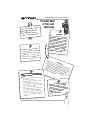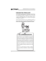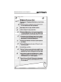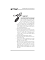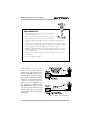
1
K-Series © 1998 by Crown International, Inc., P.O. Box 1000, Elkhart, IN 46515-1000 U.S.A. Telephone: 219-294-8000. Fax: 219-294-8329. Trademark Notice: Balanced Current Amplifier™, and BCA™ are trademarks and Crown ® is a registered trademark of Crown International, Inc. Other trademarks are the property of their respective owners. Commercial 120 VAC North American Units Only: Audio ® E106377 Watch for these symbols: Lightning Bolt Symbol: This symbol is used to alert the user to the presence of dangerous voltages and the possible risk of electric shock. Exclamation Mark Symbol: This symbol is used to alert the user to make special note of important operating or maintenance instructions found in the reference manual. 102010-2 2/98 K-Series Balanced Current Amplifier™ k, Ill be Hi! I'm Mic the degiving you your tails about s Amp!! new K-Serie Friendly Page of Tips and Warnings d operRead all safety an before ating instructions K- Se rie s op er at in g th e w al l am pl ifi er. Fo llo fully and instructions care gs given. heed any warnin om qualified serfrom Obtain assistance fr of the following y an if el nn rso vice pe occurs: or plug has been • The power cord y. wa any in damaged liquid has fallen • Foreign objects or losure. enc ier plif am into the en exposed to be has • The amplifier rtially or totally rain or has been pa id. liqu any in immersed been dropped or • The amplifier has en damaged. be has s ssi the cha d change in perrke ma • You notice a eries amp othformance, or your K-S ar to operate pe ap not es erwise do normally. Page 2 CAUTION : D o n o t lo c a te s e n s it iv e , high-gain equipmen t such a s p re a m p li fi e rs o r ta p e decks dir ectly abo ve or below the unit. If a n equipm e n t ra c k is u s ed, we re c o m m e n d lo c a ti n g th e amplifier( s) in the b ottom of the rack and the p reamplifi e r o r o th e r s e n s it iv e equipmen t at the to p. Driv in may g h e a v Im y t e m cause p l o a d s f p o r t a n pera ar ts o t ture be a of th r s u s t a : s in l circu armed.T which w e amplif ed peri o i h rem itry ens e ampl ill be ho er’s cas ds of ti ain w ur es e ifier t to r e m e t o to ’s i m harm el f u l t l b e l o w aximum n t e r n a l u c h . B u ach o th e am any lev tempe protecti t don’t ra on plifie el tha t mi tur e lev r. ght els w be ill ifier -Series ampl Keep your K at, he of s ce sour away from . en ov diator or such as a ra your nd ou rr su or r Do not cove may aterial which amp with m a as ch su , retain heat rtain. blanket or cu K-Series Balanced Current Amplifier™ Do n spil ot dr op l an (or y fo or d obje omes reign t int ct or l ic) o th iqu i am e plif K-Ser d ier. ies your n a e l p C ies am K-Ser th a wi ! only cloth damp Protect the power cord attached to your K-Series amplifier. Route it to avoid foot traffic or other situations where the cord might be stretched or pinched. Pay special attention to the cord connector and attachment points. WAR N the r ING: Sh isk o ock h f not e a xpos fire or ele zard. To redu ture. e thi ctric s c D s amp o not im unit to ra hock, do e lifier mers i n in an your e you or mois y a r othe mplifier liquid. D K-Serie r sta o s n ndin ear a po not ope g wa ra ol, ba ter. thtub te or DO N O GRO T BYP A U USE NDING SS OR D D O E MAK ON TH R POLA FEAT T H RIZA E SU E K-S POL ERIE TION E RE A A FUL RIZED P LL BLA S AMP MEAN LI S LY D O COR INSER WER P ES ON FIERS. THE D, R TED LUG THA E I T W CEPTA NTO TH CAN BE ILL BE U CLE OR E EXTE NS O SED WIT THER O ION H TH U E UN TLET IT. Page 3 K-Series Balanced Current Amplifier™ Unpacking Your K-Series Amp Please unpack and inspect your amplifier for any damage that may have occurred during transit. If damage is found, notify the transportation company immediately. Only you can initiate a claim for shipping damage. Crown will be happy to help as needed. Save the shipping carton as evidence of damage for the shipper’s inspection. We also recommend that you save all packing materials so you will have them if you ever need to transport the unit. NEVER SHIP THE UNIT WITHOUT THE FACTORY PACK. FCC COMPLIANCE NOTICE This equipment has been tested and found to comply with the limits for a Class A digital Device, pursuant to Part 15 of the FCC Rules. These limits are designed to provide reasonable protection against harmful interference when the equipment is operated in a commercial environment. This equipment generates, uses and can radiate radio frequency energy and, if not installed and used in accordance with the instruction manual, may cause harmful interference to radio communications. Operation of this equipment in a residential area is likely to cause harmful interference in which case the user will be required to correct the interference at his own expense. “The user is cautioned that any changes or modifications not expressly approved by Crown International could void the user’s authority to operate the equipment.” Page 4 K-Series Balanced Current Amplifier™ Page 5 K-Series Balanced Current Amplifier™ Quick Start! First things first. We know you just can’t wait to crank up your new Crown® K-Series amplifier. And the last thing you want to do is dig through pages of tech-talk to find out where the “ON” switch is. So that’s why we provided you with this quick and simple page to get you up and running right away. Just take a few minutes to read through this—no more than five or ten, max—you’ll be glad you did. 1. Make sure the K-Series amp and all other equipment is turned OFF before you begin wiring. The amp power switch, which is located on the far right side of the front panel, is “OFF” when pressed downward. 2. Mount your K-Series amp securely in the rack. 3. Connect the left and right inputs coming from your mixer, preamp, or other processor. You can use either balanced 1/4-inch phone or 3-pin XLR connectors. You can also choose to run in MONO mode, with either bridged outputs, “Y” inputs, or both. If so, see the sections starting on page 14 for further instructions. 4. Connect the output wiring (left and right speakers). 5. Connect your K-Series amp and other equipment to the appropriate power source. 6. Turn on your mixer, preamp, signal processor, or any other equipment in your system EXCEPT your K-Series amplifier. (Remember: save the best for last.) 7. Make sure the Channel 1 and Channel 2 level (volume) controls on your K-Series amplifier are turned all the way down (counter-clockwise), then flip the power switch “ON” (press upward). Note: After a two-second delay, the “Enable” light will glow a bright green to indicate power is on. If no audio signal is present at the amp, the enable light will then switch to a dim green. Page 6 K-Series Balanced Current Amplifier™ 8. (Now comes the fun!) Supply input, adjust amp levels and enjoy. CAUTION: Excessive output levels may toast your speakers. Crown’s K-Series amplifier has such low distortion, you may not realize the actual level being reached until it’s too late. Please exercise caution and drive your speakers responsibly, or at least warn your neighbors! 9. You may notice that your K-Series amplifier becomes warm to the touch after a few minutes of use. Don’t be alarmed. This is a normal operating condition for your K-Series amplifier. The K-Series of amplifiers are designed to be convection cooled, and therefore radiate heat passively to the enviroment. Refer to page 26 for more details. Typical Stereo Hookup 1 2 - - Page 7 K-Series Balanced Current Amplifier™ Page 8 K-Series Balanced Current Amplifier™ Contents 1 2 3 4 5 6 Friendly Page of Tips and Warnings ...................... 2 Unpacking Your K-Series Amplifier ........................ 4 Features ................................................................ 5 Quick Start ............................................................ 6 Welcome ............................................................. 10 Very Detailed Install ............................................. 14 Operation ............................................................ 21 Other Issues ........................................................ 26 Specifications ..................................................... 31 Service ................................................................ 36 Illustrations Typical Stereo Hookup .......................................... 7 The K-Series Amplifier .................................... 10-11 The Big Picture: Controls, Indicators and Connectors ................................................... 12-13 2.1 Mounting Dimensions .......................................... 14 2.2 Mono Mode Switches .......................................... 15 2.3 Input Sensitivity Switch ........................................ 15 2.4 Typical Input Wiring ............................................. 16 2.5 Stereo Output Wiring ........................................... 17 2.6 Bridge Mono Output Wiring ................................. 18 2.7 Stereo Hookup .................................................... 19 2.8 Bridged-Mono Output Hookup ............................ 19 2.9 “Y” Mono Input Hookup ....................................... 20 2.10 “Y” Mono Input / Bridged Output ......................... 20 3.1 Front Panel Indicators & Controls ........................ 21 3.2 Back Panel Controls ............................................ 23 3.3 Back Panel Fuse Location ................................... 25 4.1 Balanced & Unbalanced Input Wiring ................. 28 4.2 Balanced Input Wiring ......................................... 29 4.3 Unbalanced Input Wiring .................................... 30 5.1 Awesome Frequency (Amplitude) Response ....... 35 5.2 Superior Damping Factor .................................... 35 1.1 1.2 Page 9 K-Series Balanced Current Amplifier™ 1 Welcome Thank you for choosing Crown! Mick and his team of enthusiastic engineers have worked long hours to craft a totally new kind of amplifier—the K-Series. These are the first amplifiers to incorporate Crown’s patented BCA™ (Balanced Current Amplifier™) technology, and we are all very proud to have invented them. Our Balanced Current Amplifier makes use of a special type of circuitry which allows high levels of power output without all of the associated heat you find in a conventional amplifier. And that’s very good news for you! How high is the power output? The K1 amplifier produces an impressive 1,500 watts and weighs only 32 pounds, while the K2 produces a whopping 2,500 watts while weighing only 38 pounds; both without using a cooling fan!* Of course, the absence of a cooling fan means your amp runs quieter (no fan noise) and cleaner (no need for filters) and requires very little maintenance (we thought you’d like that). * 1,500 watts and 2,500 watts total from both channels (for the K1 and K2 respectively; 750 and 1,250 watts per channel). See the Specifications section for details. Page 10 K-Series Balanced Current Amplifier™ Fig. 1.1 The K-2 Amplifier (K-1 Amplifier appears the same except for nameplate) The K-Series amplifiers are also highly energy-efficient—some of the World’s first “green” amps. As a result, the K-Series amps use less electricity (reducing your utility bills) and save the precious resources of our environment. And that’s not all! Your K-Series amp can drive an amazing range of loudspeakers, making it one of the most versatile amplifiers ever. Plus, your K-Series has one of our most sophisticated (and totally automatic) protection systems, so your amplifier will keep working long after other amplifiers have shut down. It’s part of our philosophy: Your show must go on! This manual will help you correctly set up and use your new amplifier—we strongly recommend you read all instructions, warnings and cautions. Also, for your protection, please send in your warranty registration card today. And save your bill of sale—it’s your official proof of purchase. Page 11 K-Series Balanced Current Amplifier™ Fig. 1.2 The Big Picture: Controls, Indicators & Connectors Page 12 K-Series Balanced Current Amplifier™ Note: K1 amplifier and CE (European) versions of both amplifiers feature identical front and back panel layouts except for product nameplates and fuse specifications. Page 13 K-Series Balanced Current Amplifier™ 2 Very Detailed Install Follow these instructions for a detailed explanation of K-Series installation procedures and options. If you just want to get up and running as quickly as possible, see the Quick Start section on page 6. 1. Begin with the amplifier turned off and disconnected from the power receptacle. The K-Series power switch is located on the right side of the front panel; it is OFF when depressed downward. Equipment that will be connected to the inputs of the amplifier (such as mixers or preamplifiers) should also be turned off. 2. Mount the amplifier. Your K-Series amp is designed to be mounted in a standard, 19-inch (48.3-cm) equipment rack. It has been furnished with a convenient, 3-foot-long AC power cord. To meet system compliance, this cord must be plugged into a local, rack-mounted, commercial grade electrical outlet box. Extension cords are not to be used. The amp has a unique front-panel design which provides exceptional air circulation between K-Series amps, which makes it easy to keep your amplifiers cool. (See the section “You Gotta Know When To Kool It!” on page 26 for hints on amplifier cooling.) Fig. 2.1 Mounting Dimensions When mounting your amp in a rack, you should secure the back of the rack as well as the front. Even though the amp’s center of gravity is toward the front, securing the amp at both front and rear will assure that the amp stays in place, even when the rack is transported. Page 14 K-Series Balanced Current Amplifier™ 3. Set the mono mode switches. Both the Bridge Output and “Y” input switches should be in the OFF position when you’re running in Stereo Mode. Stereo Mode allows independent inputs on the right and left channels to feed separate speakers at the output. It’s the configuration typically chosen for everyday audio applications. Fig. 2.2 Mono Mode Switches Turn the Bridge Output switch to ON to have a single input that feeds to a single output with twice the voltage of Stereo Mode. Use this configuration if you want to give up stereo capabilities in order to drive your speakers louder. (You might also choose to use this configuration if you are running a distributed sound system from the K-Series amp.) Turn the “Y” input switch to ON if you want both inputs to be connected in parallel. Use this configuration if you want a common audio signal to feed out to two channels, each having its own level control. You might use this setup if you’re running to a monitor speaker on one channel and a main speaker stack on the other channel. You may also want to configure your system to take advantage of both the Bridge Output and “Y” input capabilities. This would allow you to have daisy-chained inputs fed to a double-the-voltage output. (See further instructions on daisy-chained inputs in the discussion on connecting the inputs in step 5 in this section.) 4. Set the Input Sensitivity switches of each channel to the desired setting. Two choices are available: 1.4 V for full rated output, or a fixed voltage gain of 26 dB. (The KSeries ship from the factory with default settings of 1.4 V, which translates to approximately 33 dB of gain.) Fig. 2.3 Input Sensitivity Switch Page 15 K-Series Balanced Current Amplifier™ 5. Connect the inputs of the K-Series amp to your mixer, preamplifier, or other equipment ahead of the amp. Two types of balanced input connectors are provided, allowing you to choose either 1/4-inch phone or 3-pin XLR connectors. You can also choose to use either balanced or unbalanced wiring. (See the section Balancing the Line on page 28 for an explanation of balanced vs. unbalanced wiring.) Input Wiring Tips 1. For all input connectivity, use shielded wire only. Cables with a foil wrap shield or a high-density braid are superior. Cables with a stranded spiral shield, although very flexible, will break down over time and cause noise problems. 2. Try to avoid using unbalanced lines with professional equipment. If you have no choice, keep the cables as short as possible. (Refer to the section Balancing the Line on page 28.) 3. To minimize hum and crosstalk, avoid running low-level input, high-level output and AC power feeds in the same path. Try to run differing signal paths at 90° to one another. If you must use a common path for all cables, use a star-quad cable for the low-level signals. 4. When changing input connectors or wiring, turn the amplifier level controls all the way down (counter-clockwise). 5. When changing output connections, a professional will turn the amplifier level down and the AC power off to minimize the chance of short-circuiting the output. If the Bridge Output switch is ON, only the Channel 1 input connectors should be used. If only the “Y” input switch is ON, then either set of connectors can be used. Fig. 2.4 Typical Input Wiring Page 16 K-Series Balanced Current Amplifier™ If you are running with both the Y-Input and Bridge Output switches “ON”, you may choose to make use of the unused input connectors as daisy-chain outputs—perhaps to other amplifiers in your system. For instance, if you’re running in “Y” mono mode and you connect the input signal to the Channel 1 XLR connector, you can use the Channel 2 XLR connector plus the two 1/4-inch phone plugs for daisy-chained outs. This simplifies your wiring needs, making good use of all the components in your system. Output Wiring Tips 1. To prevent possible short circuits, wrap or otherwise insulate exposed loudspeaker cable connectors. 2. Do not use connectors that might accidentally tie conductors together when making or breaking the connection (for example, a standard, 1/4" stereo phone plug). 3. Never use connectors that could be plugged into AC power sockets. Accidental AC input will be an electrifying experience for your equipment. But you will find out real quick if your speakers are any good at 60 Hz! 4. Avoid using connectors with low current-carrying capacity, such as XLRs. 5. Do not use connectors that have any tendency to short. 6. Connect the outputs of the K-Series amp to your loudspeakers. If the Bridge Output switch is turned OFF, connect the positive (+) and negative (–) leads of each loudspeaker to the appropriate Channel 1 and Channel 2 output connectors as shown in Figure 2.5. Fig. 2.5 Stereo Output Wiring Page 17 K-Series Balanced Current Amplifier™ If the Bridge Output switch is turned ON, connect a mono load across the red binding posts of each channel as shown in Figure 2.6. Do NOT use the black binding posts when the Bridge Output switch is turned on. Fig. 2.6 Bridge Mono Output Wiring Notice that the Channel 1 red binding post is positive (+) and the Channel 2 red binding post is negative (–) when the Bridge Output switch is turned on. The black binding posts should not be used. Never short or parallel the output channels of a K-Series amplifier to itself or to any other amplifier. Detailed diagrams of the four possible input-to-output configurations (stereo, bridged-mono, “Y” mono, and “Y” input to bridged-mono) are shown on the following pages. 7. Turn on all equipment ahead of the amplifier such as the mixer or preamplifier. Adjust their signal levels to their optimum “signal to noise” settings. 8. Plug the amplifier into the power receptacle, turn on the amplifier and adjust its level controls to a desired setting. See instructions on page 22 if this is the first time the amplifier is being turned on. uple of o C t x e The N w Some o h S s e Pag -up l Hook a c i p y T s... Option Page 18 K-Series Balanced Current Amplifier™ Fig. 2.7 Stereo Hookup— two stacks, one amp, stereo in, stereo out. 1 2 - - Fig. 2.8 Bridged-Mono Output Hookup— mono or stereo In, mono out—great for subs...or when you want it LOUD! Page 19 K-Series Balanced Current Amplifier™ Fig. 2.9 “Y” Mono Input Hookup—Great for when you want independent level controls for monitors and main stacks Fig. 2.10 “Y” Mono Input to Bridged-Mono Output Hookup—When you want plenty of power such as running a sub-bass and you need to daisy chain the input signal. Page 20 K-Series Balanced Current Amplifier™ Fig. 3.1 Front Panel Indicators & Controls 3 Operation Operating a K-Series amp is really fun! Indicators TLC: The TLC (thermal level control) indicators turn on with a dim glow a little before the amplifier needs help dissipating heat. This forewarning gives you a chance to turn on a fan or other auxiliary cooling (if available) or turn down the level controls of the amplifier. If you do neither, the amplifier will automatically begin to protect itself with its TLC protection system by subtly and dynamically reducing the gain as needed. The TLC indicators gradually turn brighter as the TLC protection becomes greater. Clip: The orange Clip indicators turn on when distortion of any type becomes audible in the amplifier output. For the first time in its 50 year history, Crown has added clip lights to an amplifier. We had resisted this feature in the past because our IOC system was more sensitive than clip indicators. We know that having good information at the right time is vital for success in business, and so we felt an indicator telling you the waveform had just been “clipped” was too little, too late. But now you have a choice! If you want to know when you are in trouble, look at the clip light. If you want to know before you are in trouble, look at the IOC light. Page 21 K-Series Balanced Current Amplifier™ IOC: The yellow Input/Output Comparator indicators are super-sensitive distortion indicators that turn on long before distortion is audible (approximately 1⁄30th the level that would trigger one of the Clip indicators). This circuit compares the actual waveforms of the input and output. It immediately alerts you of any distortion that exceeds 0.05% to provide dynamic proof of distortion-free performance. The IOC indicators include a pulse-stretching feature that helps make them more noticeable even with rapid transient signals. Signal: The green Signal indicators flash dimly when a very low-level signal (as low as 10 mW) is present in the output. They flash brightly when a louder signal (at least 1 watt) is present at the output. Enable: The green Enable indicator turns on when your KSeries amp has been turned on and has power. When first turned on, there will be a brief (two second) delay while the amplifier performs a quick start-up test. Then the Enable indicator will turn on to its full brightness. If no signal is present, the Enable indicator will switch to a dimmer green. Controls Level: You can adjust each channel’s output using the calibrated level control on the front of the amplifier. To turn down the level, rotate the control counter-clockwise. To turn up the level, rotate it clockwise. Power: The power switch is located on the front panel so you can easily turn the amplifier on or off. When the switch is depressed downward, the amp is off. If you ever need to make any wiring or installation changes, don’t forget to also disconnect the power cord. Please follow these steps when first turning on your amplifier: 1 Turn down the level of your audio source. For example, set your mixer’s volume to “∞” (off). 2 Turn down the amplifier’s level controls (counter-clockwise to 100 dB). 3 Turn on the power switch. The amplifier will go through a start-up test that lasts just a couple of seconds. Afterward, the enable indicator beside the switch will turn on to full brightness. Page 22 K-Series Balanced Current Amplifier™ Fig. 3.2 Back Panel Controls Note: Your amplifier is equipped with a state-of-the-art softstart feature so you do not need to delay the turn-on of KSeries amplifiers in large installations. 4 After the Enable light turns on, test the operating range of your input by turning up the level of your audio source to the highest possible operating level. 5 S-L-O-W-L-Y turn up the level controls on the front of the amplifier until the maximum desired loudness or power level is achieved. Be prepared for astounding output! 6 Turn down the level of your audio source to its normal range. Input Sensitivity: The input sensitivity setting determines the overall gain of the amplifier. Although you might me tempted to configure your amp to get as much gain as possible (after all, you just paid lots of money for this little beauty), you should instead look at your operating conditions and adjust the input sensitivity accordingly. First, check to make sure your mixer or console is being operated at optimum signal-to -noise, without clipping the output. (Refer to the owner’s manual for information on how to check this.) Then, with your amplifier’s input sensitivity set to the 26 dB position, turn up your amp’s level controls until you achieve the desired level (loudness). If you turn the level controls all the way up, and it’s still not loud enough, check the following: Page 23 K-Series Balanced Current Amplifier™ 1) Verify that the mixer is operating at its correct output level. See if there is a +4/-10 dB switch on the output; if so, set it to the +4 dB position. 2) Turn the amplifier level controls all the way down (counter-clockwise). Then, move the sensitivity switch to the 1.4-V position. This will increase the gain of the amplifier; 5.5 dB for the K1 and 7 dB for the K2. Now carefully turn the amplifier level controls up (clockwise) to the desired level (loudness). Take care when you are adjusting the level controls at this input sensitivity setting. Increasing the input sensitivity of the amplifier may cause the input stage of the amp to overload, so be prepared to back down the output of the mixer by 1 or 2 dB if you notice the amplifier’s clip indicators beginning to flash. K1 - Full Power into 8 Ohms Sensitivity Power at 8 ohms Gain 1.4 V (+5.21 dBu) 350 W 31.55 dB 2.65 V (+10.7 dBu) 350 W 26 dB K2 - Full Power into 8 Ohms Sensitivity Power at 8 ohms Gain 1.4 V (+5.21 dBu) 475 W 32.88 dB 3.09 V (+12 dBu) 475 W 26 dB Note: Bold type indicates selectable option on amplifier. Note: 0 dB on the mixer = +4 dBu Page 24 K-Series Balanced Current Amplifier™ Bridge Output: This on/off switch combines the two amplifier output channels into a single mono channel with twice the voltage of the single channels. This means the output will be much more powerful! It does this by bridging the outputs, and it requires special loudspeaker wiring. Do not use the black binding post outputs when the Bridge Output switch is turned on.. Connecting anything to the black binding posts may result in a visit by the Binding-Post Police. (See Section 2 for more information.) When the Bridge Output switch is turned on, only the Channel 1 level control will work. “Y” Input: This on/off switch combines the two amplifier input channels by “Y-ing” or paralleling them together. When the “Y” Input switch is turned on, a signal fed into either input channel will be fed to both outputs and the individual level controls of each channel will continue to work independently. Fuses A fuse is provided to protect the power supplies from excess current. It is located on the back panel below the power cord. A 20amp fuse should be used for all K-2 amplifiers, while a 15-amp fuse should be used for all K-1 amplifiers that are configured to use 100-120 VAC power. A 10-amp fuse should be used for all units configured to use 200-250 VAC power. IMPORTANT: Contact a Crown Service Center or our Technical Support Group for information on changing fuses. Fig. 3.3 Back Panel Fuse Location Page 25 K-Series Balanced Current Amplifier™ 4 Other Issues Ya Gotta Know When to Kool It! Your K-Series amplifier has been designed from the ground up to be a high-output amplifier that is totally convection cooled—meaning no fan is required. This goal was achieved through a variety of means: First, we forgot to include the fan in the bill of materials. Second, our balanced-current circuitry produces power much more efficiently than conventional amplifier circuits. Third, the amplifier case and front panel were designed for increased airflow and superior heat dissipation. The smoothly molded front panel was also designed to allow the center of gravity to be moved forward, placing it closer to its mounting axis. While providing strength and rigidity, the die-cast panel also protects the front panel controls and indicators from inadvertent abuse. Until now, all professional audio systems had either internal or external auxiliary air systems facilitating the cooling of the electronics. With the K-Series, we have made fans unnecessary for normal operation! If you are operating the K-Series amp in very high ambient temperatures, or if you notice theTLC indicators starting to illuminate, do not despair! Typically, modest amounts of air movement will enable your amp to dissipate any excessive heat and regain its normal composure. Due to the wide range of operating conditions present in the field, each installation needs to be considered independently for optimum thermal operation. If your TLC indicators illuminate, consider the following possible causes: 1) Insufficient air movement. 2) Overdriving of the input stage (severely into clip). 3) Very low-impedance loads. 4) High ambient temperatures. Normally, two or more of these situations must be present in order to cause illumination of the TLC LEDs. Page 26 K-Series Balanced Current Amplifier™ If you can’t, or don’t want to change the preceding conditions, two possible alternatives are available to add the necessary air movement. First, you can add fans to direct air onto any surface of the amplifier. Second, you can space the amplifiers in the rack, allowing the top and bottom covers to act as radiators. In extreme conditions, a combination of these two methods may be required, as would be expected for proper thermal functioning of any amplifier. Regardless of your operating conditions, the K-Series amplifier only dissipates the same heat as two100-watt lightbulbs. This will be hot to touch, but even in such extreme conditions, your K-Series amplifier will not suffer any ill effects. That’s because the KSeries amplifiers contain TLC (thermal level control) systems that will begin to decrease the gain of the amplifier if the TLC indicators illuminate and no steps are taken to reduce the input signal or attempts made to improve air circulation. The amplifier will not shut down, you’ll still be rockin’ with plenty of distortion-free decibility! Page 27 K-Series Balanced Current Amplifier™ Balancing the Line A balanced audio circuit typically will have both positive (+) and negative (–) legs of the circuit that are isolated from the ground circuit. These balanced legs exhibit identical impedance characteristics with respect to ground, and may also carry the audio signal at the same level, but with opposite polarities. This results in a line that offers excellent rejection of unwanted noise. On the other hand, an unbalanced circuit usually holds one leg at ground potential, while the second leg is “hot.” Unbalanced line is less expensive, but is much more susceptible to noise, and is not usually used in professional applications. For the cleanest signal, without unwanted hum and buzz, balanced line is always recommended. It is especially helpful if you have a long cable run (over 10 feet (3 m)), since noise is easily introduced into long, unbalanced lines. BALANCED GND 1 + SHIELD 3 2 FROM SOURCE INPUT Fig. 4.1 Balanced & Unbalanced Input Wiring 1 – + 3 2 UNBALANCED + INPUT FROM SOURCE + – SHIELD SHIELD Getting Rid Of Dr. Hum and Mr. Buzz If you have noticeable hum or buzz in your system, you may want to check your cable connections to see if the unwanted noise is being introduced via a ground loop. To determine the proper wiring, first check whether the output from your source is unbalanced or balanced (if you don’t know, refer to the unit’s back panel or instruction manual). If the source is balanced, refer to Figure 4.2; if it is unbalanced refer to Figure 4.3. Next, determine if the source’s power cable is floating (ungrounded, 2-prong) or grounded (3-prong). Finally, if the source in unbalanced, check the type of wiring: twin-lead or single coax. Page 28 K-Series Balanced Current Amplifier™ Hum and Buzz Tips 1. It is imperative that all of your electrical equipment share the same power ground reference. 2. Unless you are interfacing to a microphone, the shield of the cable should only be connected at one end. (See Fig. 4.2.) 3. Do not pass signal ground between electrical components in a grounded source system 4. If you wish to avoid ground loops, it doesn’t matter if you lift the input or output signal ground for your system topology, just be consistent. Personally I prefer to lift the input signal ground and it has always been successful...so far! 5. NEVER use a ground lift adapter to lift the power ground on a 3-wire AC cord; this is not its intended purpose. It is better to have it SAFE than SILENT!! Look for the true source of the noise. 6. Even when interfacing to an unbalanced load, it is preferable to use two-conductor shielded cable. 7. Get rid of the lighting company! Check Figure 4.2 to see if your cable has been wired with the proper shield and ground connection. If the cabling is incorrect, you may be able to avoid the ground loop (and associated hum) by plugging all of your equipment into the same AC circuit (on the same breaker). If this is impractical, you will need to fix the cable to match the appropriate illustration. Or you may want to simply replace the offending cable with a commercially manufactured cable of the appropriate type. Fig. 4.2 Balanced Input Wiring Page 29 K-Series Balanced Current Amplifier™ e le mor A coup iagrams... d wiring Fig. 4.3 Unbalanced Input Wiring Page 30 K-Series Balanced Current Amplifier™ 5 Specifications Note: All specifications relate to both the K1 and K2 amplifiers in both 50- and 60-Hz versions, unless noted otherwise. Performance...Just How Good Is It? Frequency Response: ±0.25 dB from 20 Hz to 20 kHz. The frequency response is band limited with an 8-Hz doubleintegrated 3rd-order Butterworth high-pass filter and a 30-kHz 7th-order Gaussian low-pass filter. Optional Aqua-sediment filter available at your local hardware store. (See Figure 5.1.) Power Output per channel at 1 kHz with both channels driven to 0.1 % or less True THD: K2: 1,250W @ 2 ohms; 800W @ 4 ohms; 475W @ 8 ohms; bridged mono, 2,500W @ 4 ohms. K1: 750W @ 2 ohms; 550W @ 4 ohms; 350W @ 8 ohms; bridged mono, 1500W @ 4 ohms. Signal to Noise (A-weighted): >100 dB below rated power. Voltage Gain: 1.4 VRMS or a fixed voltage gain of 26 dB (back panel switchable). Damping Factor: GREAT (>3,000 from 10 to 400 Hz). (See Figure 5.2.) Line Voltage Requirements: Universal power supply can be configured to operate with 100,120, 200, 220, 230, 240, 250 VAC at 50 or 60 Hz. Adapters are acquired through an Authorized Service Center. Controls...How To Turn It On and Off Level: A calibrated rotary level control for each channel located on the front panel. Power: An on/off rocker switch located on the front panel. Input Sensitivity: A two-position switch for each channel located on the back panel near each channel’s input connectors. Can be set to 1.4 V for full output into an 8-ohm load or a fixed voltage gain of 26 dB. Bridge Output: An on/off switch located on the back panel between the input connectors which, when turned on, bridges the two output channels for twice the output voltage..WATCHOUT SPEAKERS!! Page 31 K-Series Balanced Current Amplifier™ “Y” Input: An on/off switch located on the back panel between the input connectors which, when turned on, parallels the two input channels. Indicators TLC: A TLC (thermal level control) LED for each channel which turns on with a dim glow shortly before the amplifier needs help dissipating heat. (See Pg. 21.) Clip: An orange LED for each channel which turns on when distortion of any type becomes audible in the amplifier output. (See Pg. 21.) IOC: A yellow LED for each channel which serves as a distortion indicator. The IOC indicators include a pulse-stretching feature that helps make them more noticeable even with rapid transient signals. (See Pg. 22.) Signal: A green LED for each channel which flashes dimly when a very low-level signal (as low as 10 mW) is present in the output. They flash brightly when a louder signal (at least 1 watt) is present at the output. Enable: A green LED that turns on when the amplifier has been turned on and has power. When first turned on, there will be a brief two-second delay while the amplifier performs a quick turn-on diagnostic. Then the Enable indicator will turn on to its full brightness. If no signal is present, the Enable indicator will switch to a dim level. Input/Output (Spaghetti Control) Input Connectors: One balanced ¼-inch phone jack and one 3-pin female XLR connector for each channel. Input Stage: Input is electronically balanced and employs precision 1% resistors. Input Impedance: Nominally 20 K ohms, balanced. Nominally 10 K ohms, unbalanced. Input Sensitivity: 1.4 volts for standard 1 kHz power, or 26 dB gain. Page 32 K-Series Balanced Current Amplifier™ Output Connectors: Two sets of color-coded binding posts for banana plugs, spade lugs or bare wire (European models are fruit-phobic and do not accept banana plugs). DC Output Offset: ±10 millivolts. Output Signal Stereo: Unbalanced, two-channel. Bridge-Mono: Balanced, single-channel. Channel 1 controls are active; Channel 2 should be turned down. Protection, Dont leave home without it! K-Series amplifiers are protected against shorted, open or mismatched loads; overloaded power supplies; excessive temperature, chain destruction phenomena, input overload damage and high-frequency blowups. They also protect loudspeakers from input/output DC, DC offset and turn-on/turn-off transients. TLC protection circuitry protects the amplifier from excessive heat by subtly and dynamically reducing the gain only when necessary to reduce heat levels. Transformer overheating (an extremely unlikely event) will result in a temporary shutdown; when it has cooled to a safe temperature, the transformer will automatically reset itself. Controlled slew rate voltage amplifiers prevent RF burnouts, and input overload protection is provided by the input current limit. Out-of-band low-pass and high-pass filter protect the amplifier and loads from subsonic frequencies below 8 Hz and ultrasonic frequencies above 30 kHz. Turn On: State-of-the-art “soft start” feature prevents the amplifier from drawing a large inrush current when it is first turned on and no dangerous artifacts are produced by the amplifier. (However it is recommended that all equipment ahead of the amplifier be turned on first since they may produce turn-on transients.) Page 33 K-Series Balanced Current Amplifier™ Construction Beautiful cast-aluminum front panel from hand-crafted mold. Lovingly coated with the most durable powder coat. Front panel labels are painstakingly printed in color on Lexan for durability and fingerprint resistance (fully chocolate proof). Aluminum chassis with durable black finish. Cooling: High-performance passive convection cooling system allows the amplifier to drive 2-ohm loads to high music sound levels (6 dB into clip) in a 40° C (104° F ) ambient environment . Dimensions: Standard 19-inch (48.3-cm) rack mount width (EIA RS-310-B), 3.5-inch (8.9-cm) height and 16-inch (40.6cm) depth behind front mounting surface. Weight: The K2 weighs a mere 38 pounds (17.3 kg). The K1 weighs a mere 32 pounds (14.6 kg). Center of gravity approximately 6 inches (15.2 cm) behind front mounting surface. Page 34 K-Series Balanced Current Amplifier™ Test of K2 Amp, Serial Number 106390!! 6.0 0.0 dB -10.0 -20.0 10 100 1K FREQUENCY (Hz) 10 K 100 K Fig. 5.1 Awesome Frequency (Amplitude) Response 100,000 K2 10,000 DAMPING MA-2400 1,000 Brand X 001 100 10 100 FREQUENCY (Hz) 1000 Fig. 5.2 Superior Damping Factor Provides Best Bass Control in the Industry! Page 35 K-Series Balanced Current Amplifier™ 6 Service Your amplifier should only be serviced by a fully trained technician at an authorized service center. CAUTION: To prevent electric shock, do not remove covers. No user serviceable parts inside. Refer servicing to a qualified technician. Worldwide Service Service may be obtained from an authorized service center. (Contact your local Crown/Amcron representative or our office for a list of authorized service centers.) To obtain service, simply present the bill of sale as proof of purchase along with the defective unit to an authorized service center. They will handle the necessary paperwork and repair. Remember to transport your unit in the original factory packing! North American Service Service may be obtained in one of two ways: from an authorized service center or from the factory, but not your local quick-lube center! You may choose either. It is important that you have your copy of the bill of sale as your proof of purchase. Service at a North American Service Center This method usually saves the most time and effort. Simply present your bill of sale along with the defective unit to an authorized service center to obtain service. They will handle the necessary paperwork and repair. Remember to transport the unit in the original factory packing. A list of authorized service centers in your area can be obtained from our Technical Support Group. Factory Service To obtain factory service, fill out the service information page that follows and send it along with your proof of purchase and the defective unit to the Crown factory. For warranty service, we will pay for ground shipping both ways in the United States Page 36 K-Series Balanced Current Amplifier™ after receiving copies of the shipping receipts. Shipments should be sent “UPS ground.” (If the unit is under warranty, you may send it C.O.D. for the cost of freight via UPS ground.) The factory will return it via UPS ground. Please contact us if other arrangements are required. Factory Service Shipping Instructions: 1 When sending a Crown product to the factory for service, be sure to fill out the service information form that follows and enclose it inside your unit’s shipping pack. Do not send the service information form separately. 2 To ensure the safe transportation of your unit to the factory, ship it in an original factory packing container. If you don’t have one, call or write Crown’s Parts Department. With the exception of polyurethane or wooden crates, any other packing material will not be sufficient to withstand the stress of shipping. Do not use loose, small size packing materials. Always use the original factory packing to transport the unit. 3 Do not ship the unit in any kind of cabinet (wood or metal). Ignoring this warning may result in extensive damage to the unit and the cabinet. Accessories are not needed— do not send cables and other hardware. Do not send this instruction manual, if we forget what we said, we have duplicates! If you have any questions, please call or write the Crown Technical Support Group. Crown Audio Division Technical Support / Factory Service Plant 2 SW, 1718 W. Mishawaka Rd., Elkhart, Indiana 46517 U.S.A. Telephone: 219-294-8200 800-342-6939 (North America, Puerto Rico, and Virgin Islands only) Facsimile: 219-294-8301 (Technical Support) 219-294-8124 (Factory Service) Fax Back: 219-293-9200 (North America only) 800-294-4094 (North America only) 219-294-8100 (International) http://www.crownaudio.com Internet: Page 37 YEAR 3 THREE YEAR FULL WARRANTY NORTH AMERICA SUMMARY OF WARRANTY The Crown Audio Division of Crown International, Inc., 1718 West Mishawaka Road, Elkhart, Indiana 46517-4095 U.S.A. warrants to you, the ORIGINAL PURCHASER and ANY SUBSEQUENT OWNER of each NEW Crown product, for a period of three (3) years from the date of purchase by the original purchaser (the “warranty period”) that the new Crown product is free of defects in materials and workmanship. We further warrant the new Crown product regardless of the reason for failure, except as excluded in this Warranty. ITEMS EXCLUDED FROM THIS CROWN WARRANTY This Crown Warranty is in effect only for failure of a new Crown product which occurred within the Warranty Period. It does not cover any product which has been damaged because of any intentional misuse, accident, negligence, or loss which is covered under any of your insurance contracts. This Crown Warranty also does not extend to the new Crown product if the serial number has been defaced, altered, or removed. WHAT THE WARRANTOR WILL DO We will remedy any defect, regardless of the reason for failure (except as excluded), by repair, replacement, or refund. We may not elect refund unless you agree, or unless we are unable to provide replacement, and repair is not practical or cannot be timely made. If a refund is elected, then you must make the defective or malfunctioning product available to us free and clear of all liens or other encumbrances. The refund will be equal to the actual purchase price, not including interest, insurance, closing costs, and other finance charges less a reasonable depreciation on the product from the date of original purchase. Warranty work can only be performed at our authorized service centers or at the factory. We will remedy the defect and ship the product from the service center or our factory within a reasonable time after receipt of the defective product at our authorized service center or our factory. All expenses in remedying the defect, including surface shipping costs in the United States, will be borne by us. (You must bear the expense of shipping the product between any foreign country and the port of entry in the United States and all taxes, duties, and other customs fees for such foreign shipments.) HOW TO OBTAIN WARRANTY SERVICE You must notify us of your need for warranty service not later than ninety (90) days after expiration of the warranty period. All components must be shipped in a factory pack, which, if needed, may be obtained from us free of charge. Corrective action will be taken within a reasonable time of the date of receipt of the defective product by us or our authorized service center. If the repairs made by us or our authorized service center are not satisfactory, notify us or our authorized service center immediately. DISCLAIMER OF CONSEQUENTIAL & INCIDENTAL DAMAGES YOU ARE NOT ENTITLED TO RECOVER FROM US ANY INCIDENTAL DAMAGES RESULTING FROM ANY DEFECT IN THE NEW CROWN PRODUCT. THIS INCLUDES ANY DAMAGE TO ANOTHER PRODUCT OR PRODUCTS RESULTING FROM SUCH A ATES DO NOT ALLOW THE EXCLUSION OR LIMIT ATIONS OF DEFECT. SOME ST STA LIMITA INCIDENT AL OR CONSEQUENTIAL DAMAGES, SO THE ABOVE LIMIT ATION OR INCIDENTAL LIMITA EXCLUSION MA Y NOT APPL Y TO YOU. MAY APPLY WARRANTY ALTERATIONS No person has the authority to enlarge, amend, or modify this Crown Warranty. This Crown Warranty is not extended by the length of time which you are deprived of the use of the new Crown product. Repairs and replacement parts provided under the terms of this Crown Warranty shall carry only the unexpired portion of this Crown Warranty. DESIGN CHANGES We reserve the right to change the design of any product from time to time without notice and with no obligation to make corresponding changes in products previously manufactured. Telephone: 219-294-8200. Facsimile: 219-294-8301 THIS STATEMENT OF WARRANTY SUPERSEDES ANY OTHERS CONTAINED IN THIS MANUAL FOR CROWN PRODUCTS. LEGAL REMEDIES OF PURCHASER THIS CROWN WARRANTY GIVES YOU SPECIFIC LEGAL RIGHTS, YOU MAY ALSO HAVE OTHER RIGHTS WHICH VARY FROM STATE TO STATE. No action to enforce this Crown Warranty shall be commenced later than ninety (90) days after expiration of the warranty period. 9/90 WORLDWIDE SUMMARY OF WARRANTY The Crown Audio Division of Crown International, Inc., 1718 West Mishawaka Road, Elkhart, Indiana 46517-4095 U.S.A. warrants to you, the ORIGINAL PURCHASER and ANY SUBSEQUENT OWNER of each NEW Crown1 product, for a period of three (3) years from the date of purchase by the original purchaser (the “warranty period”) that the new Crown product is free of defects in materials and workmanship, and we further warrant the new Crown product regardless of the reason for failure, except as excluded in this Crown Warranty. 3 YEAR 1 Note: If your unit bears the name “Amcron,” please substitute it for the name “Crown” in this warranty. ITEMS EXCLUDED FROM THIS CROWN WARRANTY This Crown Warranty is in effect only for failure of a new Crown product which occurred within the Warranty Period. It does not cover any product which has been damaged because of any intentional misuse, accident, negligence, or loss which is covered under any of your insurance contracts. This Crown Warranty also does not extend to the new Crown product if the serial number has been defaced, altered, or removed. HOW TO OBTAIN WARRANTY SERVICE You must notify us of your need for warranty service not later than ninety (90) days after expiration of the warranty period. All components must be shipped in a factory pack. Corrective action will be taken within a reasonable time of the date of receipt of the defective product by our authorized service center. If the repairs made by our authorized service center are not satisfactory, notify our authorized service center immediately. DISCLAIMER OF CONSEQUENTIAL & INCIDENTAL DAMAGES YOU ARE NOT ENTITLED TO RECOVER FROM US ANY INCIDENTAL DAMAGES RESULTING FROM ANY DEFECT IN THE NEW CROWN PRODUCT. THIS INCLUDES ANY DAMAGE TO ANOTHER PRODUCT OR PRODUCTS RESULTING FROM SUCH A DEFECT. WARRANTY ALTERATIONS No person has the authority to enlarge, amend, or modify this Crown Warranty. This Crown Warranty is not extended by the length of time which you are deprived of the use of the new Crown product. Repairs and replacement parts provided under the terms of this Crown Warranty shall carry only the unexpired portion of this Crown Warranty. DESIGN CHANGES We reserve the right to change the design of any product from time to time without notice and with no obligation to make corresponding changes in products previously manufactured. LEGAL REMEDIES OF PURCHASER No action to enforce this Crown Warranty shall be commenced later than ninety (90) days after expiration of the warranty period. THIS STATEMENT OF WARRANTY SUPERSEDES ANY OTHERS CONTAINED IN THIS MANUAL FOR CROWN PRODUCTS. 9/90 Telephone: 219-294-8200. Facsimile: 219-294-8301 THREE YEAR FULL WARRANTY WHAT THE WARRANTOR WILL DO We will remedy any defect, regardless of the reason for failure (except as excluded), by repair, replacement, or refund. We may not elect refund unless you agree, or unless we are unable to provide replacement, and repair is not practical or cannot be timely made. If a refund is elected, then you must make the defective or malfunctioning product available to us free and clear of all liens or other encumbrances. The refund will be equal to the actual purchase price, not including interest, insurance, closing costs, and other finance charges less a reasonable depreciation on the product from the date of original purchase. Warranty work can only be performed at our authorized service centers. We will remedy the defect and ship the product from the service center within a reasonable time after receipt of the defective product at our authorized service center. Crown Factory Service Information Shipping Address: Crown International, Inc., Factory Service, Plant 2 SW, 1718 W. Mishawaka Rd., Elkhart, IN U.S.A. 46517 Phone: 1-800-342-6939 or 1-219-294-8200 Fax: 1-219-294-8124 Owner’s Name: __________________________________________________________ Shipping Address: _______________________________________________________ Phone Number: _______________________ Fax Number: ___________________ Model: _______________________________ Serial Number: _________________ Purchase Date: __________________________________________________________ NATURE OF PROBLEM (Be sure to describe the conditions that existed when the problem occurred and what attempts were made to correct it.) _______________________________________________________________________ _______________________________________________________________________ _______________________________________________________________________ _______________________________________________________________________ _______________________________________________________________________ Other equipment in your system: __________________________________________ _______________________________________________________________________ _______________________________________________________________________ _______________________________________________________________________ _______________________________________________________________________ If warranty has expired, payment will be: ❏ Cash/Check ❏ VISA ❏ MasterCard ❏ C.O.D. Card Number:___________________________ Exp. Date: __________ Signature:____________________________ ENCLOSE THIS PORTION WITH THE UNIT. DO NOT MAIL SEPARATELY.