1
SiBE01 - 503
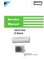
SPLIT Pair
D-Series
[Applied Models]
zNon-Inverter Pair : Heat Pump
SiBE01-503
Non Inverter Pair
D-Series
zHeat Pump
Indoor Unit
FTYN25DV3B ATY20DV2
FTYN35DV3B ATY25DV2
ATY35DV2
Outdoor Unit
RYN25DV3B
RYN35DV3B
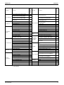
Table of Contents
ARY20DV2
ARY25DV2
ARY35DV2
i
SiBE01-503
1. Introduction .............................................................................................v
1.1 Safety Cautions ........................................................................................v
Part 1 List of Function .................................................................. 1
1. Functions.................................................................................................2
Part 2 Specifications .................................................................... 5
1. Specifications ..........................................................................................6
Part 3 Printed Circuit Board Connector Wiring Diagram ............. 9
1. Printed Circuit Board Connector Wiring Diagram..................................10
1.1 Indoor Unit..............................................................................................10
Part 4 Functions and Control...................................................... 13
1. Functions...............................................................................................14
1.1
1.2
1.3
1.4
1.5
1.6
1.7
1.8
Power-Airflow Dual Flaps, Wide-Angle Louvers and Auto-Swing ..........14
Fan Speed Control for Indoor Units........................................................15
Thermostat Control.................................................................................16
Automatic Operation...............................................................................17
Programme Dry Function .......................................................................18
Night Set Mode.......................................................................................19
POWERFUL Operation ..........................................................................20
Other Functions......................................................................................21
2. Function of Thermistor ..........................................................................22
3. Control Specification .............................................................................23
3.1
3.2
3.3
3.4
3.5
3.6
3.7
3.8
Four Way Valve Switching .....................................................................23
3-Minutes Standby .................................................................................23
Compressor Protection Function............................................................23
Fan OFF Delay.......................................................................................23
Freeze-up Protection Control .................................................................23
Heating Peak-cut Control .......................................................................24
Liquid Compression Protection Function................................................24
Defrost Control .......................................................................................25
Part 5 System Configuration....................................................... 27
1. System Configuration............................................................................28
2. Instructions............................................................................................29
2.1
2.2
2.3
2.4
2.5
2.6
2.7
2.8
2.9
ii
Safety Precautions .................................................................................29
Names of Parts.......................................................................................31
Preparation before Operation.................................................................34
AUTO • DRY • COOL • HEAT • FAN Operation .....................................37
Adjusting the Air Flow Direction .............................................................39
POWERFUL Operation ..........................................................................40
TIMER Operation ...................................................................................41
Care and Cleaning .................................................................................43
Troubleshooting......................................................................................46
Table of Contents
SiBE01-503
Part 6 Service Diagnosis............................................................. 51
1.
2.
3.
4.
Caution for Diagnosis............................................................................52
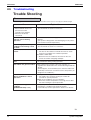
Problem Symptoms and Measures .......................................................53
Service Check Function ........................................................................54
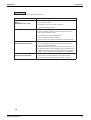
Troubleshooting ....................................................................................57
4.1
4.2
4.3
4.4
4.5
4.6
4.7
Error Codes and Description ..................................................................57
Indoor Unit PCB Abnormality .................................................................58
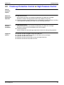
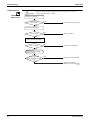
Freeze-up Protection Control or High Pressure Control.........................59
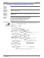
Fan Motor or Related Abnormality (AC motor).......................................61
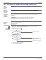
Thermistor or Related Abnormality (Indoor Unit)....................................62
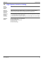
High Pressure Control in Cooling ...........................................................63
Thermistor or Related Abnormality (Outdoor Unit).................................65
5. Check ....................................................................................................67
5.1
5.2
5.3
5.4
Thermistor Resistance Check ................................................................67
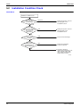
Installation Condition Check...................................................................68
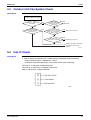
Outdoor Unit Fan System Check............................................................69
Hall IC Check .........................................................................................69
Part 7 Removal Procedure .......................................................... 71
1. Indoor Unit.............................................................................................72
1.1
1.2
1.3
1.4
1.5
1.6
1.7
Removal of Air Filter...............................................................................72
Removal of Front Grille ..........................................................................75
Removal of Horizontal Blades / Vertical Blades .....................................78
Removal of Electrical Parts Box / PCB / Swing Motor............................80
Removal of Heat Exchanger ..................................................................86
Install of Drain Plug ................................................................................89
Removal of Fan Rotor / Fan Motor.........................................................90
2. Outdoor Unit..........................................................................................94
2.1
2.2
2.3
2.4
2.5
2.6
2.7
Removal of Panels .................................................................................94
Removal of Bellmouth and Left Side Plate.............................................96
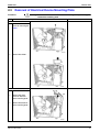
Removal of Electrical Device Mounting Plate.........................................97
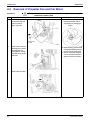
Removal of Propeller Fan and Fan Motor ..............................................98
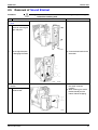
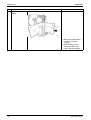
Removal of Sound Blanket.....................................................................99
Removal of Partition Plate....................................................................101
Removal of Compressor.......................................................................103
Part 8 Others ............................................................................. 105
1. Others .................................................................................................106
1.1 Trial Operation and Testing..................................................................106
1.2 Pump Down Operation .........................................................................106
1.3 Jumper Settings ...................................................................................107
Part 9 Appendix......................................................................... 109
1. Piping Diagrams..................................................................................110
1.1 Indoor Units ..........................................................................................110
1.2 Outdoor Units .......................................................................................111
2. Wiring Diagrams..................................................................................113
2.1 Indoor Units ..........................................................................................113
2.2 Outdoor Units .......................................................................................113
Table of Contents
iii
SiBE01-503
Index
............................................................................................. i
Drawings & Flow Charts ............................................................... iii
iv
Table of Contents
SiBE01-503
Introduction
1. Introduction
1.1
Safety Cautions
Cautions and
Warnings
Be sure to read the following safety cautions before conducting repair work.
Warning” and “
Caution”. The “
The caution items are classified into “
Warning”
items are especially important since they can lead to death or serious injury if they are not
followed closely. The “
Caution” items can also lead to serious accidents under some
conditions if they are not followed. Therefore, be sure to observe all the safety caution items
described below.
About the pictograms
This symbol indicates an item for which caution must be exercised.
The pictogram shows the item to which attention must be paid.
This symbol indicates a prohibited action.
The prohibited item or action is shown inside or near the symbol.
This symbol indicates an action that must be taken, or an instruction.
The instruction is shown inside or near the symbol.
After the repair work is complete, be sure to conduct a test operation to ensure that the
equipment operates normally, and explain the cautions for operating the product to the
customer.
1.1.1 Caution in Repair
Warning
Be sure to disconnect the power cable plug from the plug socket before
disassembling the equipment for a repair.
Working on the equipment that is connected to a power supply can cause an
electrical shook.
If it is necessary to supply power to the equipment to conduct the repair or
inspecting the circuits, do not touch any electrically charged sections of the
equipment.
If the refrigerant gas discharges during the repair work, do not touch the
discharging refrigerant gas.
The refrigerant gas can cause frostbite.
When disconnecting the suction or discharge pipe of the compressor at the
welded section, release the refrigerant gas completely at a well-ventilated
place first.
If there is a gas remaining inside the compressor, the refrigerant gas or
refrigerating machine oil discharges when the pipe is disconnected, and it can
cause injury.
If the refrigerant gas leaks during the repair work, ventilate the area. The
refrigerant gas can generate toxic gases when it contacts flames.
The step-up capacitor supplies high-voltage electricity to the electrical
components of the outdoor unit.
Be sure to discharge the capacitor completely before conducting repair work.
A charged capacitor can cause an electrical shock.
Do not start or stop the air conditioner operation by plugging or unplugging the
power cable plug.
Plugging or unplugging the power cable plug to operate the equipment can
cause an electrical shock or fire.
v
Introduction
SiBE01-503
Caution
Do not repair the electrical components with wet hands.
Working on the equipment with wet hands can cause an electrical shock.
Do not clean the air conditioner by splashing water.
Washing the unit with water can cause an electrical shock.
Be sure to provide the grounding when repairing the equipment in a humid or
wet place, to avoid electrical shocks.
Be sure to turn off the power switch and unplug the power cable when cleaning
the equipment.
The internal fan rotates at a high speed, and cause injury.
Do not tilt the unit when removing it.
The water inside the unit can spill and wet the furniture and floor.
Be sure to check that the refrigerating cycle section has cooled down
sufficiently before conducting repair work.
Working on the unit when the refrigerating cycle section is hot can cause burns.
Use the welder in a well-ventilated place.
Using the welder in an enclosed room can cause oxygen deficiency.
1.1.2 Cautions Regarding Products after Repair
Warning
Be sure to use parts listed in the service parts list of the applicable model and
appropriate tools to conduct repair work. Never attempt to modify the
equipment.
The use of inappropriate parts or tools can cause an electrical shock,
excessive heat generation or fire.
When relocating the equipment, make sure that the new installation site has
sufficient strength to withstand the weight of the equipment.
If the installation site does not have sufficient strength and if the installation
work is not conducted securely, the equipment can fall and cause injury.
Be sure to install the product correctly by using the provided standard
installation frame.
Incorrect use of the installation frame and improper installation can cause the
equipment to fall, resulting in injury.
Be sure to install the product securely in the installation frame mounted on a
window frame.
If the unit is not securely mounted, it can fall and cause injury.
Be sure to use an exclusive power circuit for the equipment, and follow the
technical standards related to the electrical equipment, the internal wiring
regulations and the instruction manual for installation when conducting
electrical work.
Insufficient power circuit capacity and improper electrical work can cause an
electrical shock or fire.
vi
For integral units
only
For integral units
only
SiBE01-503
Introduction
Warning
Be sure to use the specified cable to connect between the indoor and outdoor
units. Make the connections securely and route the cable properly so that there
is no force pulling the cable at the connection terminals.
Improper connections can cause excessive heat generation or fire.
When connecting the cable between the indoor and outdoor units, make sure
that the terminal cover does not lift off or dismount because of the cable.
If the cover is not mounted properly, the terminal connection section can cause
an electrical shock, excessive heat generation or fire.
Do not damage or modify the power cable.
Damaged or modified power cable can cause an electrical shock or fire.
Placing heavy items on the power cable, and heating or pulling the power cable
can damage the cable.
Do not mix air or gas other than the specified refrigerant (R410A / R22) in the
refrigerant system.
If air enters the refrigerating system, an excessively high pressure results,
causing equipment damage and injury.
If the refrigerant gas leaks, be sure to locate the leak and repair it before
charging the refrigerant. After charging refrigerant, make sure that there is no
refrigerant leak.
If the leak cannot be located and the repair work must be stopped, be sure to
perform pump-down and close the service valve, to prevent the refrigerant gas
from leaking into the room. The refrigerant gas itself is harmless, but it can
generate toxic gases when it contacts flames, such as fan and other heaters,
stoves and ranges.
When replacing the coin battery in the remote controller, be sure to disposed
of the old battery to prevent children from swallowing it.
If a child swallows the coin battery, see a doctor immediately.
Caution
Installation of a leakage breaker is necessary in some cases depending on the
conditions of the installation site, to prevent electrical shocks.
Do not install the equipment in a place where there is a possibility of
combustible gas leaks.
If a combustible gas leaks and remains around the unit, it can cause a fire.
Be sure to install the packing and seal on the installation frame properly.
For integral units
If the packing and seal are not installed properly, water can enter the room and only
wet the furniture and floor.
1.1.3 Inspection after Repair
Warning
Check to make sure that the power cable plug is not dirty or loose, then insert
the plug into a power outlet all the way.
If the plug has dust or loose connection, it can cause an electrical shock or fire.
If the power cable and lead wires have scratches or deteriorated, be sure to
replace them.
Damaged cable and wires can cause an electrical shock, excessive heat
generation or fire.
vii
Introduction
SiBE01-503
Warning
Do not use a joined power cable or extension cable, or share the same power
outlet with other electrical appliances, since it can cause an electrical shock,
excessive heat generation or fire.
Caution
Check to see if the parts and wires are mounted and connected properly, and
if the connections at the soldered or crimped terminals are secure.
Improper installation and connections can cause excessive heat generation,
fire or an electrical shock.
If the installation platform or frame has corroded, replace it.
Corroded installation platform or frame can cause the unit to fall, resulting in
injury.
Check the grounding, and repair it if the equipment is not properly grounded.
Improper grounding can cause an electrical shock.
Be sure to measure the insulation resistance after the repair, and make sure
that the resistance is 1 Mohm or higher.
Faulty insulation can cause an electrical shock.
Be sure to check the drainage of the indoor unit after the repair.
Faulty drainage can cause the water to enter the room and wet the furniture
and floor.
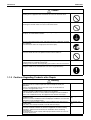
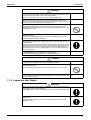
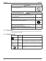
1.1.4 Using Icons
Icons are used to attract the attention of the reader to specific information. The meaning of each
icon is described in the table below:
1.1.5 Using Icons List
Icon
Type of
Information
Note
Description
A “note” provides information that is not indispensable, but may
nevertheless be valuable to the reader, such as tips and tricks.
Note:
Caution
A “caution” is used when there is danger that the reader, through
incorrect manipulation, may damage equipment, loose data, get
an unexpected result or has to restart (part of) a procedure.
Warning
A “warning” is used when there is danger of personal injury.
Reference
A “reference” guides the reader to other places in this binder or
in this manual, where he/she will find additional information on a
specific topic.
Caution
Warning
viii
SiBE01-503
Part 1
List of Function
1. Functions.................................................................................................2
List of Function
1
Functions
SiBE01-503
Functions
Inverter (with Inverter Power Control)
Comfortable
Airflow
Comfort Control
Operation
Lifestyle
Convenience
—
Air Purifying Filter with Bacteriostatic,
Virustatic Functions
—
15
~46
Photocatalytic Deodorizing Filter
—
Operation Limit for Heating (°CWB)
–10
~15
Air Purifying Filter with Photocatalytic
Deodorizing Function
—
Titanium Apatite Photocatalytic
Air-Purifying Filter
{
Longlife Filter
—
{
PAM Control
—
Oval Scroll Compressor
—
Swing Compressor
—
Mold Proof Air Filter
Rotary Compressor
{
Wipe-clean Flat Panel
{
Reluctance DC Motor
—
Washable Grille
—
Power-Airflow Flap
—
Mold Proof Operation
—
Power-Airflow Dual Flaps
{
Heating Dry Operation
—
Power-Airflow Diffuser
—
Good-Sleep Cooling Operation
—
Wide-Angle Louvers
{
Count up-down Timer
{
Vertical Auto-Swing (Up and Down)
{
Night Set Mode
{
Horizontal Auto-Swing (Right and Left)
—
Auto-Restart (after Power Failure)
{
3-D Airflow
—
Self-Diagnosis (Digital, LED) Display
{
1
Comfort Airflow Mode
—
Wiring Error Check
—
3-Step Airflow (H/P Only)
—
Auto Fan Speed
{
Anticorrosion Treatment of Outdoor Heat
Exchanger
{
Indoor Unit Silent Operation
—
Night Quiet Mode (Automatic)
—
Multi-Split / Split Type Compatible Indoor
Unit
—
Outdoor Unit Silent Operation (Manual)
—
Flexible Voltage Correspondence
—
Intelligent Eye
—
High Ceiling Application
—
Quick Warming Function
—
Chargeless
Hot-Start Function
{
Either Side Drain (Right or Left)
Automatic Defrosting
{
Power Selection
—
Automatic Operation
{
5-Rooms Centralized Controller (Option)
—
Programme Dry Function
{
Fan Only
{
Remote Control Adaptor
(Normal Open-Pulse Contact)(Option)
—
New Powerful Operation (Non-Inverter)
{
Inverter Powerful Operation
—
Remote Control Adaptor
(Normal Open Contact)(Option)
—
DIII-NET Compatible (Adaptor)(Option)
—
Priority-Room Setting
—
Cooling / Heating Mode Lock
—
Home Leave Operation
—
ECONO Mode
—
Indoor Unit On/Off Switch
{
Signal Reception Indicator
{
Temperature Display
—
Another Room Operation
—
Note: { : Holding Functions
— : No Functions
2
Functions
Operation Limit for Cooling (°CDB)
Basic Function
Compressor
Category
FTYN25-35DV3B
RYN25-35DV3B
Category
FTYN25-35DV3B
RYN25-35DV3B
1. Functions
Health & Clean
Timer
Worry Free
“Reliability &
Durability”
Flexibility
2
{
Remote Control
Remote
Controller
Wireless
{
Wired
—
1 : Digital Only
2 : 7.5m(25 class), 10m(35 class)
List of Function
Functions
Inverter (with Inverter Power Control)
Basic Function
Compressor
Comfortable
Airflow
Comfort Control
Operation
Lifestyle
Convenience
Operation Limit for Cooling (°CDB)
Operation Limit for Heating (°CWB)
–10
~15
—
Oval Scroll Compressor
—
Swing Compressor
—
Health & Clean
Air Purifying Filter with Bacteriostatic,
Virustatic Functions
—
Photocatalytic Deodorizing Filter
—
Air Purifying Filter with Photocatalytic
Deodorizing Function
—
Titanium Apatite Photocatalytic
Air-Purifying Filter
{
Rotary Compressor
{
Longlife Filter
—
Reluctance DC Motor
—
Mold Proof Air Filter
{
Power-Airflow Flap
—
Wipe-clean Flat Panel
{
Power-Airflow Dual Flaps
{
Washable Grille
—
Power-Airflow Diffuser
—
Mold Proof Operation
—
Wide-Angle Louvers
{
Heating Dry Operation
—
Vertical Auto-Swing (Up and Down)
{
Good-Sleep Cooling Operation
—
Horizontal Auto-Swing (Right and Left)
—
Count Up-down Timer
{
3-D Airflow
—
Night Set Mode
{
Comfort Airflow Mode
—
Auto-Restart (after Power Failure)
{
3-Step Airflow (H/P Only)
—
Auto Fan Speed
{
Indoor Unit Silent Operation
—
Night Quiet Mode (Automatic)
—
Outdoor Unit Silent Operation (Manual)
—
Intelligent Eye
—
Quick Warming Function
—
Hot-Start Function
{
Automatic Defrosting
Automatic Operation
Timer
Self-Diagnosis (Digital, LED) Display
Worry Free
“Reliability &
Durability”
{
Wiring Error Check
—
Anticorrosion Treatment of Outdoor Heat
Exchanger
{
Multi-Split / Split Type Compatible Indoor
Unit
—
Flexible Voltage Correspondence
—
High Ceiling Application
—
{
Chargeless
5m
{
Either Side Drain (Right or Left)
{
Programme Dry Function
{
Power Selection
—
Fan Only
{
5-Rooms Centralized Controller (Option)
—
New Powerful Operation (Non-Inverter)
{
Inverter Powerful Operation
—
Remote Control Adaptor
(Normal Open-Pulse Contact)(Option)
—
Flexibility
Remote Control
Priority-Room Setting
—
Cooling / Heating Mode Lock
—
Remote Control Adaptor
(Normal Open Contact)(Option)
—
Home Leave Operation
—
DIII-NET Compatible (Adaptor)(Option)
—
ECONO Mode
—
Wireless
{
Indoor Unit On/Off Switch
{
Wired
—
Signal Reception Indicator
{
Temperature Display
—
Another Room Operation
—
Note: { : Holding Functions
— : No Functions
List of Function
Functions
—
10
~46
PAM Control
Category
ATY20-35DV2
ARY20-35DV2
Category
Functions
ATY20-35DV2
ARY20-35DV2
SiBE01-503
Remote
Controller
: Digital Only
3
Functions
4
SiBE01-503
List of Function
SiBE01-503
Part 2
Specifications
1. Specifications ..........................................................................................6
Specifications
5
Specifications
SiBE01-503
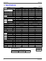
1. Specifications
50Hz 230V
Indoor Units
Models
FTYN25DV3B
RYN25DV3B
Outdoor Units
Capacity
Rated (Min.~Max.)
Moisture Removal
Running Current (Rated)
Power Consumption
Rated (Min.~Max.)
Power Factor
COP (Rated)
Liquid
Piping
Connections Gas
Drain
Heat Insulation
Indoor Units
Front Panel Color
Air Flow Rate m³/min
(cfm)
Type
Motor Output
Speed
Air Direction Control
Air Filter
Running Current (Rated)
Power Consumption (Rated)
Power Factor
Temperature Control
Dimensions (H×W×D)
Packaged Dimensions (H×W×D)
Weight
Gross Weight
Operation
H/M/L
Sound
Sound Power H
Outdoor Units
Casing Color
Type
Compressor Model
Motor Output
Type
Refrigerant
Oil
Charge
Type
Refrigerant
Charge
m³/min
Air Flow Rate
cfm
Type
Fan
Motor Output
Running Current (Rated)
Power Consumption (Rated)
Power Factor
Starting Current
Dimensions (H×W×D)
Packaged Dimensions (H×W×D)
Weight
Gross Weight
Operation
H
Sound
Sound Power H
Drawing No.
Fan
Note:
kW
Btu/h
kcal/h
L/h
A
Cooling
2.5
8,550
2,150
1.2
4.0
Heating
3
10,260
2,580
—
4.0
Cooling
3.15
10,770
2,710
1.9
5.4
Heating
3.85
13,160
3,310
—
5.8
W
830
880
1,200
1,290
%
W/W
mm
mm
mm
90
3.01
96
3.41
97
2.63
97
2.98
H
M
L
W
Steps
A
W
%
mm
mm
kg
kg
φ 6.4
φ 9.5
φ18.0
φ 6.4
φ 9.5
φ18.0
Both Liquid and Gas Pipes
FTYN25DV3B
White
7.5 (265)
7.8 (275)
6.0 (212)
6.3 (222)
4.6 (162)
4.8 (169)
Cross Flow Fan
18
3 Steps, Powerful, Auto
Right, Left, Horizontal, Downward
Removable / Washable / Mildew Proof
0.19
0.19
40
40
92
92
Microcomputer Control
273×784×195
260×840×330
9
11
Both Liquid and Gas Pipes
FTYN35DV3B
White
7.5 (265)
7.8 (275)
6.1 (215)
6.4 (226)
4.9 (173)
5.2 (184)
Cross Flow Fan
18
3 Steps, Powerful, Auto
Right, Left, Horizontal, Downward
Removable / Washable / Mildew Proof
0.19
0.19
40
40
92
92
Microcomputer Control
273×784×195
260×840×330
9
11
dBA
39 / 33 / 27
39 / 33 / 27
39 / 34 / 29
dBA
57
57
57
W
L
kg
W
A
W
%
A
mm
mm
kg
kg
39 / 34 / 29
57
RYN35DV3B
Ivory White
Hermetically Sealed Rotary Type
5KS150DBK21
1,100
FV50S
0.43
R410A
1.0
28
25.2
988
890
Propeller
23
5.21
5.61
1,160
1,250
97
97
23.1
560×695×265
607×824×337
36
40
RYN25DV3B
Ivory White
Hermetically Sealed Rotary Type
5PS112DAH21
750
FV50S
0.35
R410A
0.9
28
25.2
988
890
Propeller
23
3.81
3.81
790
840
90
96
18.6
560×695×265
607×824×337
31
35
dBA
47
49
48
49
dBA
62
64
63
64
3D048831
3D048830
MAX. interunit piping length: 15m
MAX. interunit height difference: 10m
Amount of additional charge of refrigerant 20g/m for piping length exceeding 7.5m(25 class), 10m(35class)
The data are based on the conditions shown in the table below.
Cooling
Indoor ; 27°CDB/19°CWB
Outdoor ; 35°CDB/24°CWB
6
FTYN35DV3B
RYN35DV3B
Heating
Indoor ; 20°CDB
Outdoor ; 7°CDB/6°CWB
Piping Length
Conversion Formulae
kcal/h=kW×860
Btu/h=kW×3414
cfm=m³/min×35.3
7.5m
Specifications
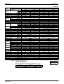
SiBE01-503
Specifications
50Hz 220V
Indoor Units
Models
ATY20DV2
ARY20DV2
Outdoor Units
Capacity
Moisture Removal
Running Current
Power Consumption
Power Factor
COP
Liquid
Piping
Connections Gas
Drain
Heat Insulation
Indoor Units
Front Panel Color
Air Flow Rate m³/min
(cfm)
Type
Motor Output
Speed
Air Direction Control
Air Filter
Running Current
Power Consumption
Power Factor
Temperature Control
Dimensions (H×W×D)
Packaged Dimensions (H×W×D)
Weight
Gross Weight
Operation
H/M/L
Sound
Outdoor Units
Casing Color
Type
Compressor Model
Motor Output
Type
Refrigerant
Oil
Charge
Type
Refrigerant
Charge
m³/min
Air Flow Rate
cfm
Type
Fan
Motor Output
Running Current
Power Consumption
Power Factor
Starting Current
Dimensions (H×W×D)
Packaged Dimensions (H×W×D)
Weight
Gross Weight
Operation Sound
Drawing No.
Fan
Note:
kW
Btu/h
kcal/h
L/h
A
W
%
W/W
mm
mm
mm
H
M
L
W
Steps
A
W
%
mm
mm
kg
kg
dBA
Cooling
1.95
6,700
1,680
0.8
3.6
680
86
2.87
Heating
2.3
7,900
1,980
—
3.2
600
85
3.83
Cooling
2.5
8,500
2,150
1.2
4.0
840
95
2.98
Heating
2.8
9,600
2,410
—
3.6
770
97
3.64
φ 6.4
φ 9.5
φ18.0
φ 6.4
φ 9.5
φ18.0
Both Liquid and Gas Pipes
ATY20DV2
White
7.2 (254)
7.5 (265)
5.9 (208)
6.2 (219)
4.6 (162)
4.8 (169)
Cross Flow Fan
18
3 Steps, Powerful, Auto
Right, Left, Horizontal, Downward
Removable / Washable / Mildew Proof
0.19
0.19
40
40
96
96
Microcomputer Control
273×784×195
260×840×330
9
11
Both Liquid and Gas Pipes
ATY25DV2
White
7.5 (265)
7.8 (275)
6.0 (212)
6.3 (222)
4.6 (162)
4.8 (169)
Cross Flow Fan
18
3 Steps, Powerful, Auto
Right, Left, Horizontal, Downward
Removable / Washable / Mildew Proof
0.19
0.19
40
40
96
96
Microcomputer Control
273×784×195
260×840×330
9
11
38 / 33 / 27
W
L
kg
W
A
W
%
A
mm
mm
kg
kg
dBA
38 / 33 / 27
39 / 33 / 27
ARY20DV2
Ivory White
Hermetically Sealed Rotary Type
2R13C225BSA
600
ATMOS M60 or SUNISO 4GDID
0.3
R22
0.75
28
25.2
988
890
Propeller
23
3.41
3.01
640
560
85
85
14
560×695×265
607×824×337
26
28
46
47
3D048822
Heating
Indoor ; 20°CDB
Outdoor ; 7°CDB/6°CWB
39 / 33 / 27
ARY25DV2
Ivory White
Hermetically Sealed Rotary Type
2P16C225ANF
750
ATMOS M60 or SUNISO 4GDID
0.35
R22
0.75
28
25.2
988
890
Propeller
23
3.81
3.41
800
730
95
97
15.6
560×695×265
607×824×337
28
31
46
47
3D048821
MIN. interunit piping length: 3m
MAX. interunit piping length: 12m
MAX. interunit height difference: 10m
Amount of additional charge of refrigerant 20g/m for piping length exceeding 5m
The data are based on the conditions shown in the table below.
Cooling
Indoor ; 27°CDB/19°CWB
Outdoor ; 35°CDB/24°CWB
Specifications
ATY25DV2
ARY25DV2
Conversion Formulae
kcal/h=kW×860
Btu/h=kW×3414
cfm=m³/min×35.3
Piping Length
5m
7
Specifications
SiBE01-503
50Hz 220V
Indoor Units
Models
ATY35DV2
ARY35DV2
Outdoor Units
Capacity
Moisture Removal
Running Current
Power Consumption
Power Factor
COP
Liquid
Piping
Connections Gas
Drain
Heat Insulation
Indoor Units
Front Panel Color
Air Flow Rate m³/min
(cfm)
Type
Motor Output
Speed
Air Direction Control
Air Filter
Running Current
Power Consumption
Power Factor
Temperature Control
Dimensions (H×W×D)
Packaged Dimensions (H×W×D)
Weight
Gross Weight
Operation
H/M/L
Sound
Outdoor Units
Casing Color
Type
Compressor Model
Motor Output
Type
Refrigerant
Oil
Charge
Type
Refrigerant
Charge
m³/min
Air Flow Rate
cfm
Type
Fan
Motor Output
Running Current
Power Consumption
Power Factor
Starting Current
Dimensions (H×W×D)
Packaged Dimensions (H×W×D)
Weight
Gross Weight
Operation Sound
Drawing No.
Fan
Note:
kW
Btu/h
kcal/h
L/h
A
W
%
W/W
mm
mm
mm
Heating
3.8
13,000
3,270
—
5.6
1,180
96
3.22
φ 6.4
φ12.7
φ18.0
Both Liquid and Gas Pipes
ATY35DV2
White
H
M
L
7.5 (265)
6.1 (215)
4.9 (173)
A
W
%
7.8 (275)
6.4 (226)
5.2 (184)
Cross Flow Fan
18
3 Steps, Powerful, Auto
Right, Left, Horizontal, Downward
Removable / Washable / Mildew Proof
W
Steps
0.19
40
96
dBA
0.19
40
96
Microcomputer Control
273×784×195
260×840×330
9
11
mm
mm
kg
kg
39 / 34 / 29
39 / 34 / 29
ARY35DV2
Ivory White
Hermetically Sealed Rotary Type
2K22C225EUE
1,100
ATMOS M60 or SUNISO 4GDID
0.41
R22
0.95
W
L
kg
28
988
W
A
W
%
A
mm
mm
kg
kg
dBA
25.2
890
Propeller
23
5.21
1,070
93
5.41
1,140
96
22.8
560×695×265
607×824×337
36
40
47
48
3D048820
MIN. interunit piping length: 3m
MAX. interunit piping length: 12m
MAX. interunit height difference: 10m
Amount of additional charge of refrigerant 20g/m for piping length exceeding 5m
The data are based on the conditions shown in the table below.
Cooling
Indoor ; 27°CDB/19°CWB
Outdoor ; 35°CDB/24°CWB
8
Cooling
3.3
11,300
2,840
1.9
5.4
1,110
93
2.97
Heating
Indoor ; 20°CDB
Outdoor ; 7°CDB/6°CWB
Conversion Formulae
kcal/h=kW×860
Btu/h=kW×3414
cfm=m³/min×35.3
Piping Length
5m
Specifications
SiBE01-503
Part 3
Printed Circuit Board
Connector Wiring Diagram
1. Printed Circuit Board Connector Wiring Diagram..................................10
1.1 Indoor Unit..............................................................................................10
Printed Circuit Board Connector Wiring Diagram
9
Printed Circuit Board Connector Wiring Diagram
SiBE01-503
1. Printed Circuit Board Connector Wiring Diagram
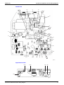
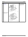
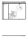
1.1
Indoor Unit
Connectors
1) S1
2) S2, S4
3) S5
4) S6
5) S7
6) S26
7) S27
8) S32
9) S33
10) H1
11) H2, H4
12) H3
13) H5
Note:
10
Connector for fan motor
Connector for transformer
Connector for thermal fuse
Connector for swing motor (horizontal blades)
Connector for fan motor (Hall IC)
Connector for control PCB
Connector for signal receiver PCB
Connector for indoor heat exchanger thermistor
Connector for outdoor heat exchanger thermistor
Connector for compressor (outdoor unit)
Connector for four way valve (outdoor unit)
Connector for fan motor (outdoor unit)
Connector for power supply (outdoor unit)
Other designations
1) V1, V2
Varistor
2) JA
Address setting jumper
JC
Power failure recovery function (auto restart)
∗ Refer to page 107 for detail.
3) SW1
Forced operation ON/OFF switch
4) LED1
LED for operation (green)
5) LED2
LED for timer (yellow)
6) LED A
LED for service monitor (green)
7) FU1
Fuse (3.15A)
8) RTH
Room temperature thermistor
Printed Circuit Board Connector Wiring Diagram
SiBE01-503
Printed Circuit Board Connector Wiring Diagram
Control PCB
FU1
H1
V1
S2
H2
S1
V2
H3
S4
H4
S5
H5
S7
S6
S33
S27
LED A
J30
JC
JA
S32
(R4670)
Signal Receiver PCB
LED1
LED2
S26
RTH
SW1
(R4671)
Printed Circuit Board Connector Wiring Diagram
11
Printed Circuit Board Connector Wiring Diagram
12
SiBE01-503
Printed Circuit Board Connector Wiring Diagram
SiBE01-503
Part 4
Functions and Control
1. Functions...............................................................................................14
1.1
1.2
1.3
1.4
1.5
1.6
1.7
1.8
Power-Airflow Dual Flaps, Wide-Angle Louvers and Auto-Swing ..........14
Fan Speed Control for Indoor Units........................................................15
Thermostat Control.................................................................................16
Automatic Operation...............................................................................17
Programme Dry Function .......................................................................18
Night Set Mode.......................................................................................19
POWERFUL Operation ..........................................................................20
Other Functions......................................................................................21
2. Function of Thermistor ..........................................................................22
3. Control Specification .............................................................................23
3.1
3.2
3.3
3.4
3.5
3.6
3.7
3.8
Functions and Control
Four Way Valve Switching .....................................................................23
3-Minutes Standby .................................................................................23
Compressor Protection Function............................................................23
Fan OFF Delay.......................................................................................23
Freeze-up Protection Control .................................................................23
Heating Peak-cut Control .......................................................................24
Liquid Compression Protection Function................................................24
Defrost Control .......................................................................................25
13
Functions
SiBE01-503
1. Functions
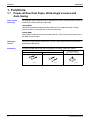
1.1
Power-Airflow Dual Flaps, Wide-Angle Louvers and
Auto-Swing
Power-Airflow
Dual Flaps
The large flaps send a large volume of air downwards to the floor. The flap provides an optimum
control area in cooling, heating and dry mode.
Heating Mode
During heating mode, the large flap enables direct warm air straight downwards. The flap
presses the warm air above the floor to reach the entire room.
Cooling Mode
During cooling mode, the flap retracts into the indoor unit. Then, cool air can be blown far and
pervaded all over the room.
Wide-Angle
Louvres
The louvres, made of elastic synthetic resin, provide a wide range of airflow that guarantees a
comfortable air distribution.
Auto-Swing
The following table explains the auto-swing process for heating, cooling, dry and fan :
Vertical Swing (up and down)
Cooling, Dry
Heating, Fan
Horizontal Swing
(right and left: manual)
0˚
25˚
0˚
5˚
30˚
25˚
50˚
5˚
50˚
30˚
(R2946)
14
(R4013)
(R2817)
Functions and Control
SiBE01-503
1.2
Functions
Fan Speed Control for Indoor Units
Control Mode
The air flow rate can be automatically controlled depending on the difference between the set
temperature and the room temperature. This is done through phase control and Hall IC control.
For more information about Hall IC, refer to troubleshooting for fan motor on page 61.
Phase Steps
Phase control and fan speed control contains 7 steps:LL, L, LM, M, HM, H, and HH.
You can choose the airflow rate between L and HH with the remote controller
Step
LL
L
LM
M
HM
H
HH (Powerful)
Cooling
—
Heating
Thermostat OFF
Dry
L tap only
(900-1020rpm)
(R4721)
(R4722)
{= The airflow rate is chosen from L-M-H tap when the fan setting button is set
Note:
Air Flow Rate
Control for
Heating
to automatic.
1. During powerful operation, fan operates at 1340-1390rpm.
2. Fan stops during defrost operation.
3. In time of thermostat OFF, the fan rotates at following speed.
Cooling : The fan keeps rotating at the set tap.
Heating : The fan rotates at LL tap.
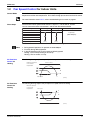
The following drawing explains the principle for fan speed control for heating:
Difference between
room and set
temperature
Phase control
L
1˚C
2˚C
M
3˚C
H
Fan speed
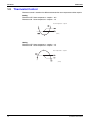
Air Flow Rate
Control for
Cooling
(R4723)
The following drawing explains the principle of fan speed control for cooling:
Difference between
room and set
temperature
Fan speed
H
3˚C
2˚C
M
1˚C
L
Phase control
Functions and Control
(R4724)
15
Functions
1.3
SiBE01-503
Thermostat Control
Thermostat control is based on the difference between the room temperature and the setpoint.
Cooling
Thermostat OFF: Room temperature – setpoint ≤ 0°C
Thermostat ON : Room temperature – setpoint ≥ 1°C
Room temperature – setpoint
ON
1˚C
0˚C
OFF
(R4725)
Heating
Thermostat OFF: Room temperature – setpoint ≥ 2°C
Thermostat ON : Room temperature – setpoint ≤ 1°C
Room temperature – setpoint
OFF
2˚C
1˚C
ON
(R4726)
16
Functions and Control
SiBE01-503
1.4
Functions
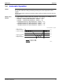
Automatic Operation
Outline
When the automatic mode is selected with the remote controller, the microcomputer determines
the operation mode from cooling and heating according to the room temperature and the
setpoint.
The unit automatically switches the operation mode to cooling or heating to maintain the room
temperature.
Details of the
Control
Target temperature equals setpoint plus correction value (cooling:+1°C, heating: –1°C)
Mode switching point and operation ON/OFF point are as follows.
Cooling → Heating: Room temperature – setpoint ≤ – 2°C
Heating → Cooling: Room temperature – setpoint ≥ + 2°C
Cooling thermostat ON : Room temperature – setpoint ≥ + 2°C
Cooling thermostat OFF: Room temperature – setpoint ≤ + 1°C
Heating thermostat ON : Room temperature – setpoint ≤ – 2°C
Heating thermostat OFF: Room temperature – setpoint ≥ – 1°C
Room temperature – setpoint
Heating→Cooling
Cooling thermostat ON
+2˚C
Cooling thermostat OFF
+1˚C
0˚C
–1˚C
Heating thermostat OFF
Cooling→Heating
Heating thermostat ON
–2˚C
Cooling
Compressor ON
Compressor OFF
Functions and Control
Heating
Cooling
(R4728)
17
Functions
1.5
SiBE01-503
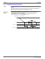
Programme Dry Function
Outline
Programme dry function removes humidity while preventing the room temperature from
lowering.
Since the microcomputer controls both the temperature and air flow rate, the temperature
adjustment and fan adjustment buttons are inoperable in this mode.
Details of the
Control
The microcomputer automatically sets the target temperature and fan setting (L tap).
Target temperature is determined as follows.
Room temperature ≥ 18°C: Target temperature = room temperature at startup
Room temperature < 18°C: Target temperature = 18°C
Room temperature – target temperature
0˚C
–1˚C
Compressor
6 min.
ON
OFF
ON
Fan OFF delay
Indoor unit fan
L tap
OFF
5 sec.
OFF
L tap
(R4727)
18
Functions and Control
SiBE01-503
1.6
Functions
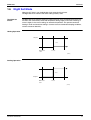
Night Set Mode
When the OFF timer is set, the Night Set circuit automatically activates.
The Night Set circuit maintains the airflow setting made by users.
The Night Set
Circuit
The Night Set circuit continues heating or cooling the room at the set temperature for the first
one hour, then automatically lowers the temperature setting slightly in the case of heating, or
raises it slightly in the case of cooling, for economical operations. This prevents excessive
heating in winter and excessive cooling in summer to ensure comfortable sleeping conditions,
and also conserves electricity.
Heating Operation
Setpoint
–1˚C
OFF timer
1 hour
start
(R4730)
Cooling Operation
+1˚C
Setpoint
OFF timer
1 hour
start
(R4729)
Functions and Control
19
Functions
1.7
SiBE01-503
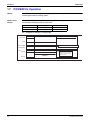
POWERFUL Operation
Outline
In order to exploit the cooling and heating capacity to full extent, operate the air conditioner by
increasing the indoor fan rotating speed.
Details of the
Control
When POWERFUL button is pushed, the fan speed and the target temperature will be
converted to the following states for 20 minutes.
Operation mode
Cooling
Heating
Fan speed
HH tap
HH tap
Target temperature
18°C
30°C
Ex.) : POWERFUL operation in cooling mode.
Target temp.
Set temp.
18˚C
Powerful ON
It counts 20 min. also in the remote controller.
Powerful OFF
Fan
HH tap
Set tap
20min.
Ending condition: "or" in 1 to 3
1. After the lapse of 20 minutes.
2. Powerful operation is OFF.
3. Operation halts.
(R4731)
20
Functions and Control
SiBE01-503
1.8
Functions
Other Functions
1.8.1 Hot Start Function
In order to prevent the cold draft that normally comes when heating operation starts, the
temperature of the indoor heat exchanger is detected, and either the air flow is stopped or is
made very weak thereby carrying out comfortable heating of the room.
*The cold draft is also prevented using a similar control when the thermostat turns OFF.
1.8.2 Signal Receiving Sign
When the indoor unit receives a signal from the remote controller, the unit emits a signal
receiving sound.
1.8.3 ON/OFF Button on Indoor Unit
An ON/OFF button is provided on the front panel of the unit. Use this button when the remote
controller is missing or if its battery has run out.
Pressing the ON/OFF button cycles through the following operation modes: cooling → OFF
→ heating → OFF → cooling, etc. Since the operation mode is not displayed, you have to
judge what mode the unit is in by feeling whether the air coming out of the vent is cold or hot.
The operation mode refers to the following table.
Mode
COOL
HEAT
Temperature setting
22°C
26°C
Air flow rate
AUTO
AUTO
1.8.4 Titanium Apatite Photocatalytic Air-Purifying Filter
This filter combines the Air Purifying Filter and Titanium Apatite Photocatalytic Deodorizing
Filter in a single highly effective unit. The filter traps microscopic particles, decompose odours
and even deactivates bacteria and viruses. It lasts for three years without replacement if
washed about once every six months.
1.8.5 Mold Proof Air Filter
The filter net is treated with mold resisting agent TBZ (harmless, colorless, and odorless). Due
to this treatment, the amount of mold growth is much smaller than that of normal filters.
1.8.6 Self-Diagnosis Digital Display
The microcomputer continuously monitors operating conditions of the indoor unit, the outdoor
unit, and the entire system. When an abnormality occurs, the remote controller displays error
code on the LCD. These indications allow prompt maintenance operations.
1.8.7 Auto-restart Function
Even if a power failure (including one for just a moment) occurs during the operation, the
operation restarts in the condition before power failure automatically when power is restored.
(Note) It takes 3 minutes to restart the operation because the 3-minutes standby function is
activated.
Functions and Control
21
Function of Thermistor
SiBE01-503
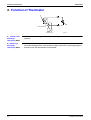
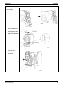
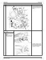
2. Function of Thermistor
A
B
Four way valve
Compressor
(R4733)
A Outdoor Heat
Exchanger
Thermistor (DCB)
1. The outdoor heat exchanger thermistor is used for high pressure control during cooling
operation.
B Indoor Heat
Exchanger
Thermistor (DCN)
1. The indoor heat exchanger thermistor is used to prevent freezing.
During the cooling operation, if the temperature drops abnormally, the operating frequency
becomes lower, then the operation must be halted.
22
Functions and Control
SiBE01-503
Control Specification
3. Control Specification
3.1
Four Way Valve Switching
Outline
Current is conducted during heating operation, and current is not conducted during cooling or
defrosting. In order to eliminate the switching sound (as the four way valve coil switches from
ON to OFF) when the heating is stopped, the delay switch of the four way valve is carried out
after the operation stopped.
Detail
The four way valve is switched 2 minutes after the compressor stops.
3.2
3-Minutes Standby
Prohibit to turn ON the compressor for 3 minutes after turning it off.
(except when defrosting)
3.3
Compressor Protection Function
When the compressor turns ON, it keeps running at least 120 seconds.
(except when defrosting)
3.4
Fan OFF Delay
The fan stops 30 seconds after the compressor stops.
(except when defrosting)
3.5
Freeze-up Protection Control
Outline
Detail
During cooling/dry operation, freeze-up protection control is activated according to the
temperature of the indoor heat exchanger to prevent it freezing.
Conditions for starting
Temperature of the indoor heat exchanger ≤ 0°C
Compressor running time ≥ 10 minutes
While controlling
The compressor halts.
The indoor fan rotates at L tap.
Conditions for ending
Temperature of the indoor heat exchanger ≥ 13°C
or
The operation stops.
Functions and Control
23
Control Specification
3.6
Outline
Detail
SiBE01-503
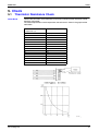
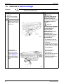
Heating Peak-cut Control
During heating operation, heating peak-cut control is activated according to the temperature of
the indoor heat exchanger to prevent abnormal high pressure.
Conditions for starting
Temperature of the indoor heat exchanger ≥ 63°C (FTYN models), 65°C (ATY models)
While controlling
The compressor halts.
The outdoor fan switches ON/OFF according to the temperature of the indoor heat
exchanger.
Conditions for ending
Temperature of the indoor heat exchanger < 42°C
or
Cooling or dry mode starts.
or
The operation stops.
Outdoor fan
OFF
ON
Compressor
OFF
ON
42˚C
49˚C
55˚C
63˚C (FTYN models)
65˚C (ATY models)
(R4734)
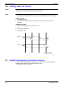
3.7
Liquid Compression Protection Function
In order to obtain the dependability of the compressor, the outdoor fan switches ON/OFF
according to the temperature of the outdoor heat exchanger.
(The temperature differs by models.)
24
Functions and Control
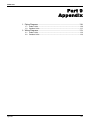
SiBE01-503
3.8
Control Specification
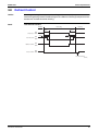
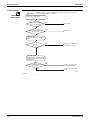
Defrost Control
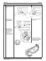
Outline
In heating, defrosting is carried out by the cooling cycle (reverse cycle) to prevent the outdoor
heat exchanger being frosted. The defrosting time or outdoor heat exchanger temperature must
be more than its fixed value when finishing.
Detail
Time chart for 35 class
Heating
Defrosting
Heating
86sec.
Compressor
86sec.
ON
OFF
73sec.
Four way valve
Outdoor unit fan
Indoor unit fan
73sec.
ON
OFF
ON
OFF
ON
OFF
Hot start function
(R4734)
Functions and Control
25
Control Specification
26
SiBE01-503
Functions and Control
SiBE01-503
Part 5
System Configuration
1. System Configuration............................................................................28
2. Instructions............................................................................................29
2.1
2.2
2.3
2.4
2.5
2.6
2.7
2.8
2.9
System Configuration
Safety Precautions .................................................................................29
Names of Parts.......................................................................................31
Preparation before Operation.................................................................34
AUTO • DRY • COOL • HEAT • FAN Operation .....................................37
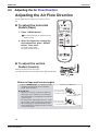
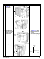
Adjusting the Air Flow Direction .............................................................39
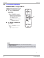
POWERFUL Operation ..........................................................................40
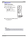
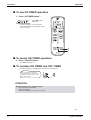
TIMER Operation ...................................................................................41
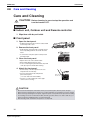
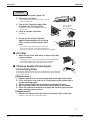
Care and Cleaning .................................................................................43
Troubleshooting......................................................................................46
27
System Configuration
SiBE01-503
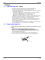
1. System Configuration
After the installation and test operation of the room air conditioner have been completed, it
should be operated and handled as described below. Every user would like to know the correct
method of operation of the room air conditioner, to check if it is capable of cooling (or heating)
well, and to know a clever method of using it.
In order to meet this expectation of the users, giving sufficient explanations taking enough time
can be said to reduce about 80% of the requests for servicing. However good the installation
work is and however good the functions are, the customer may blame either the room air
conditioner or its installation work because of improper handling. The installation work and
handing over of the unit can only be considered to have been completed when its handling has
been explained to the user without using technical terms but giving full knowledge of the
equipment.
28
System Configuration
SiBE01-503
Instructions
2. Instructions
Note:
2.1
This instruction is for FTYN models as representative.
Safety Precautions
Safety precautions
•
•
•
•
Keep this manual where the operator can easily find them.
Read this manual attentively before starting up the unit.
For safety reason the operator must read the following cautions carefully.
This manual classifies precautions into WARNING and CAUTION. Be sure to follow all precautions
below: they are all important for ensuring safety.
WARNING
CAUTION
If you do not follow these instructions exactly, the unit may
cause property damage, personal injury or loss of life.
If you do not follow these instructions exactly, the unit may
cause minor or moderate property damage or personal injury.
Never do.
Be sure to follow the instructions.
Be sure to earth the air conditioner.
Never cause the air conditioner (including the remote
controller) to get wet.
Never touch the air conditioner (including the remote
controller) with a wet hand.
WARNING
• In order to avoid fire, explosion or injury, do not operate the unit when harmful, among which flammable or
corrosive gases, are detected near the unit.
• It is not good for health to expose your body to the air flow for a long time.
• Do not put a finger, a rod or other objects into the air outlet or inlet. As the fan is rotating at a high speed, it will
cause injury.
• Do not attempt to repair, relocate, modify or reinstall the air conditioner by yourself. Incorrect work will cause electric
shocks, fire etc.
For repairs and reinstallation, consult your Daikin dealer for advice and information.
• The refrigerant used in the air conditioner is safe. Although leaks should not occur, if for some
reason any refrigerant happens to leak into the room, make sure it does not come in contact
with any flame as of gas heaters, kerosene heaters or gas range.
• If the air conditioner is not cooling (heating) properly, the refrigerant may be leaking, so call your dealer.
When carrying out repairs accompanying adding refrigerant, check the content of the repairs with our service staff.
• Do not attempt to install the air conditioner by your self. Incorrect work will result in water leakage, electric shocks or
fire. For installation, consult the dealer or a qualified technician.
• In order to avoid electric shock, fire or injury, if you detect any abnormally such as smell of fire, stop the operation and
turn off the breaker. And call your dealer for instructions.
CAUTION
• The air conditioner must be earthed. Incomplete earthing may result in electric shocks. Do not connect the
earth line to a gas pipe, water pipe, lightning rod, or a telephone earth line.
• In order to avoid any quality deterioration, do not use the unit for cooling precision instruments, food, plants,
animals or works of art.
• Never expose little children, plants or animals directly to the air flow.
• Do not place appliances which produce open fire in places exposed to the air flow from the unit or under the
indoor unit. It may cause incomplete combustion or deformation of the unit due to the heat.
• Do not block air inlets nor outlets. Impaired air flow may result in insufficient performance or trouble.
2
System Configuration
29
Instructions
SiBE01-503
• Do not stand or sit on the outdoor unit. Do not place any object on the unit to avoid injury, do not remove the fan guard.
• Do not place anything under the indoor or outdoor unit that must be kept away from moisture. In certain conditions,
moisture in the air may condense and drip.
• After a long use, check the unit stand and fittings for damage.
• Do not touch the air inlet and aluminum fins of outdoor unit. It may cause injury.
• The appliance is not intended for use by young children or infirm persons without supervision.
• Young children should be supervised to ensure that they do not play with the appliance.
• To avoid oxygen deficiency, ventilate the room sufficiently if equipment with burner is used together with the
air conditioner.
• Before cleaning, be sure to stop the operation, turn the breaker off or pull out the supply cord.
• Do not connect the air conditioner to a power supply different from the one as specified. It may cause trouble or fire.
• Depending on the environment, an earth leakage breaker must be installed. Lack of an earth leakage breaker may
result in electric shocks.
• Arrange the drain hose to ensure smooth drainage. Incomplete draining may cause wetting of the building, furniture
etc.
• Do not operate the air conditioner with wet hands.
• Do not wash the indoor unit with excessive water, only use a slightly wet cloth.
• Do not place things such as vessels containing water or anything else on top of the unit. Water may penetrate into the unit and degrade electrical insulations, resulting in an electric shock.
Installation site.
To install the air conditioner in the following types of environments, consult the dealer.
• Places with an oily ambient or where steam or soot occurs.
• Salty environment such as coastal areas.
• Places where sulfide gas occurs such as hot springs.
• Places where snow may block the outdoor unit.
The drain from the outdoor unit must be discharged to a place of good drainage.
Consider nuisance to your neighbours from noises.
For installation, choose a place as described below.
• A place solid enough to bear the weight of the unit which does not amplify the operation noise or vibration.
• A place from where the air discharged from the outdoor unit or the operation noise will not annoy
your neighbours.
Electrical work.
• For power supply, be sure to use a separate power circuit dedicated to the air conditioner.
System relocation.
• Relocating the air conditioner requires specialized knowledge and skills. Please consult the dealer if relocation is necessary for moving or remodeling.
3
30
System Configuration
SiBE01-503
2.2
Instructions
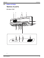
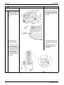
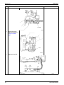
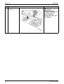
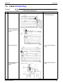
Names of Parts
Names of parts
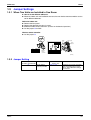
Indoor Unit
1
2
3
4
5
6
10
9
8
7
11
12
13
14
ON
OFF
4
System Configuration
31
Instructions
SiBE01-503
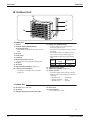
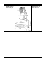
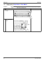
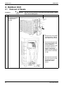
Outdoor Unit
15
17
18
19
16
Indoor Unit
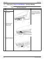
1. Air filter
2. Titanium Apatite Photocatalytic
Air-Purifying Filter:
• These filters are attached to the inside of the air
filters.
3. Air inlet
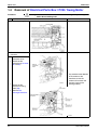
4. Front panel
5. Panel tab
6. Room temperature sensor:
• It senses the air temperature around the unit.
7. Display
8. Air outlet
9. Flaps (horizontal blades): (page 12.)
10. Louvres (vertical blades):
• The louvers are inside of the air outlet.
(page 12.)
11. Indoor Unit ON/OFF switch:
• Push this switch once to start operation.
Push once again to stop it.
• This switch is useful when the remote controller
is missing.
• Pressing the switch in an emergency allows
you to select cooling or heating. (page 11.)
• The operation mode refers to the following
table.
Mode
COOL
HEAT
Temperature
setting
22°C
26°C
Air flow rate
AUTO
AUTO
12. Operation lamp (green)
13. TIMER lamp (yellow): (page 14.)
14. Signal receiver:
• It receives signals from the remote controller.
• When the unit receives a signal, you will hear a
short beep.
• Operation start .............beep-beep
• Settings changed..........beep
• Operation stop ..............beeeeep
Outdoor Unit
15. Air inlet: (Back and side)
18. Drain hose
16. Air outlet
19. Earth terminal:
• It is inside of this cover.
17. Refrigerant piping and inter-unit cable
5
32
System Configuration
SiBE01-503
Instructions
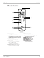
Remote Controller
1
2
4
5
3
6
7
8
10
9
11
< ARC445A1 >
1. Signal transmitter:
• It sends signals to the indoor unit.
2. Display:
• It displays the current settings.
(In this illustration, each section is shown
with all its displays ON for the purpose of
explanation.)
3. POWERFUL button:
POWERFUL operation (page 13.)
4. ON/OFF button:
• Press this button once to start operation.
Press once again to stop it.
• The button glows even in dark rooms.
6. MODE selector button:
• It selects the operation mode.
(AUTO/DRY/COOL/HEAT/FAN) (page 10.)
7. FAN setting button:
• It selects the air flow rate setting.
8. SWING button: (page 12.)
9. ON TIMER button: (page 15.)
10. OFF TIMER button: (page 14.)
11. TIMER CANCEL button:
• It cancels the timer setting.
5. TEMPERATURE adjustment buttons:
• It changes the temperature setting.
6
System Configuration
33
Instructions
2.3
SiBE01-503
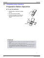
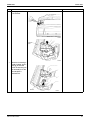
Preparation before Operation
Preparation Before Operation
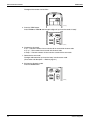
To set the batteries
1
1. Pull the tabs on top down and open
the lid.
2. Set two dry batteries (AAA).
3. Insert the two tabs in the bottom of
the lid and close the lid as it was
before.
Top tab
3
2
Lower tabs
(2 places)
ATTENTION
About batteries
• When replacing the batteries, use batteries of the same type, and replace the two old batteries
together.
• When the system is not used for a long time, take the batteries out.
• We recommend replacing once a year, although if the remote controller display begins to fade or if
reception deteriorates, please replace with new alkali batteries. Do not use manganese batteries.
• The attached batteries are provided for the initial use of the system.
The usable period of the batteries may be short depending on the manufactured date of the air
conditioner.
7
34
System Configuration
SiBE01-503
Instructions
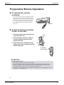
Preparation Before Operation
To operate the remote
controller
• To use the remote controller, aim the transmitter
at the indoor unit. If there is anything to block
signals between the unit and the remote controller, such as a curtain, the unit will not operate.
• Do not drop the remote controller. Do not get it wet.
• The maximum distance for communication is
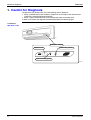
about 7 m.
Receiver
To fix the remote controller
holder on the wall
1. Choose a place from where the signals reach the unit.
2 Push
2. Fix the holder to a wall, a pillar, or
similar location with the screws
procured locally.
3. Place the remote controller on the
bottom tabs of the remote controller
holder and push.
1 Set
To remove,
pull it upwards.
ATTENTION
About remote controller
• Never expose the remote controller to direct sunlight.
• Dust on the signal transmitter or receiver will reduce the sensitivity. Wipe off dust with soft cloth.
• Signal communication may be disabled if an electronic-starter-type fluorescent lamp (such as
inverter-type lamps) is in the room. Consult the shop if that is the case.
• If the remote controller signals happen to operate another appliance, move that appliance to somewhere else, or consult the shop.
8
System Configuration
35
Instructions
SiBE01-503
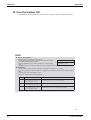
Turn the breaker ON
• Turning ON the breaker opens the flap, then closes it again. (This is a normal procedure.)
NOTE
Tips for saving energy
• Be careful not to cool (heat) the room too much.
Recommended temperature setting
Keeping the temperature setting at a moderate level helps save energy.
• Cover windows with a blind or a curtain.
For cooling:26°C – 28°C
Blocking sunlight and air from outdoors increases the cooling (heating)
For heating:20°C – 24°C
effect.
• Clogged air filters cause inefficient operation and waste energy. Clean them once in about every two weeks.
Please note
• The air conditioner always consumes 15-35 watts of electricity even while it is not operating.
• If you are not going to use the air conditioner for a long period, for example in spring or autumn, turn the breaker
OFF.
• If the flap opens, turn on the breaker to close it.
• Use the air conditioner in the following conditions.
Mode
Operating conditions
If operation is continued out of this range
COOL
Outdoor temperature: 15 to 46 °C
Indoor temperature: 18 to 32 °C
Indoor humidity: 80% max.
• A safety device may work to stop the operation.
• Condensation may occur on the indoor unit and drip.
HEAT
Outdoor temperature: –10 to 20 °C
Indoor temperature: 14 to 28 °C
• A safety device may work to stop the operation.
DRY
Outdoor temperature: 15 to 46 °C
Indoor temperature: 18 to 32 °C
Indoor humidity: 80% max.
• A safety device may work to stop the operation.
• Condensation may occur on the indoor unit and drip.
• Operation outside this humidity or temperature range may cause a safety device to disable the system.
9
36
System Configuration
SiBE01-503
2.4
Instructions
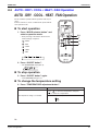
AUTO • DRY • COOL • HEAT • FAN Operation
AUTO · DRY · COOL · HEAT · FAN Operation
The air conditioner operates with the operation mode of your
choice.
From the next time on, the air conditioner will operate with the
same operation mode.
To start operation
1. Press “MODE selector button” and
select a operation mode.
2,3
1
• Each pressing of the button advances the
mode setting in sequence.
: AUTO
4
: DRY
5
: COOL
: HEAT
: FAN
2. Press “ON/OFF button” .
• The OPERATION lamp lights up.
ON
OFF
To stop operation
3. Press “ON/OFF button” again.
• Then OPERATION lamp goes off.
To change the temperature setting
4. Press “TEMPERATURE adjustment button”.
DRY or FAN mode
AUTO or COOL or HEAT mode
Press “
“
The temperature setting is not variable.
” to raise the temperature and press
” to lower the temperature.
Set to the temperature you like.
C
10
System Configuration
37
Instructions
SiBE01-503
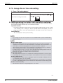
To change the air flow rate setting
5. Press “FAN setting button”.
DRY mode
AUTO or COOL or HEAT or FAN mode
Three levels of air flow rate setting from “
The air flow rate setting is not variable.
plus “
” to “
”
” are available.
Settings using the indoor unit operation switches
The main body operation switch should only be used in emergencies when the remote control is
lost or broken, its battery has run out, or it is otherwise unusable.
Operation mode
• Pressing the main body operation switch cycles through the following operation modes: cooling
→ off → heating → off → cooling, etc. Since the operation mode is not displayed, you have to
judge what mode the unit is in by feeling whether the air coming out of the vent is cold or hot.
Swing Setting
• The unit will operate with the previous setting.
NOTE
• If the settings were made with the operation switch, the ON/OFF TIMER operation and NIGHT SET
MODE are cleared.
NOTE
Note on HEAT operation
• Since this air conditioner heats the room by taking heat from outdoor air to indoors, the heating
capacity becomes smaller in lower outdoor temperatures. If the heating effect is insufficient, it is recommended to use another heating appliance in combination with the air conditioner.
• The heat pump system heats the room by circulating hot air around all parts of the room. After the
start of heating operation, it takes some time before the room gets warmer.
• In heating operation, frost may occur on the outdoor unit and lower the heating capacity. In that case,
the system switches into defrosting operation to take away the frost.
• During defrosting operation, hot air does not flow out of indoor unit.
Note on DRY operation
• The computer chip works to rid the room of humidity while maintaining the temperature as much as possible.
It automatically controls temperature and fan strength, so manual adjustment of these functions is unavailable.
Note on AUTO operation
• In AUTO operation, the system selects an appropriate operation mode (COOL or HEAT) based on the
room temperature at the start of the operation.
• The system automatically reselects setting at a regular interval to bring the room temperature to user-setting level.
• If you do not like AUTO operation, you can manually select the operation mode and setting you like.
Note on air flow rate setting
• At smaller air flow rates, the cooling (heating) effect is also smaller.
11
38
System Configuration
SiBE01-503
2.5
Instructions
Adjusting the Air Flow Direction
Adjusting the Air Flow Direction
You can adjust the air flow direction to increase your comfort.
To adjust the horizontal
blades (flaps)
1. Press “SWING button”.
The display will light up and the flaps will
begin to swing.
2. When the flaps have reached the
desired position, press “SWING
button” once more.
1,2
The display will go blank.
The flaps will stop moving.
To adjust the vertical
blades (louvers)
Hold the knob and move the louvers.
(You will find a knob on the left-side and the right-side blades.)
Notes on flaps and louvers angles
• When “ SWING button ” is selected, the flaps
swinging range depends on the operation
mode. (See the figure.)
ATTENTION
• Always use a remote controller to adjust the
flaps angle. If you attempt to move it forcibly
with hand when it is swinging, the mechanism
may be broken.
• Be careful when adjusting the louvers. Inside
the air outlet, a fan is rotating at a high speed.
• When changing the operation mode in automatic operation, the swings may move in order
to correct the angle.
In DRY mode or COOL mode
When stop operation
Upper limit in cooling
0°
25°
Lower limit in cooling
In HEAT or FAN mode
When stop operation
5°
Upper limit in heating
30°
Lower limit in heating
12
System Configuration
39
Instructions
2.6
SiBE01-503
POWERFUL Operation
POWERFUL Operation
POWERFUL operation quickly maximizes the cooling
(heating) effect. You can get the maximum capacity.
■ To start POWERFUL
operation
1. Press “POWERFUL button”.
• POWERFUL operation ends in 20 minutes.
Then the system automatically operates
again with the settings which were used
before POWERFUL operation.
• When using POWERFUL operation,
there are some functions which are not
available.
• “
” is displayed on the LCD.
1,2
■ To cancel POWERFUL
operation
2. Press “POWERFUL button”
again.
• “
” disappears from the LCD.
NOTE
■ Notes on POWERFUL operation
• POWERFUL operation is not available in modes other than cooling or heating.
• In COOL and HEAT mode
To maximize the cooling (heating) effect, the air flow rate be fixed to the maximum setting.
The temperature and air flow settings are not variable.
13
40
System Configuration
SiBE01-503
2.7
Instructions
TIMER Operation
TIMER Operation
Timer functions are useful for automatically switching the air
conditioner on or off at night or in the morning. You can also use
OFF TIMER and ON TIMER in combination.
■ To use OFF TIMER operation
1. Press “OFF TIMER button”.
ON
OFF
The TIMER lamp
lights up.
• The time changes in 1 hour increments every
time the button is pushed, with a maximum of 9
hours.
2
1
■ To cancel the OFF TIMER operation
2. Press “CANCEL button”.
• The TIMER lamp goes off.
NOTE
■ NIGHT SET MODE
When the OFF TIMER is set, the air conditioner automatically adjusts the temperature
setting (1.0˚C up in COOL, 1.0˚C down in HEAT) to prevent excessive cooling (heating) for
your pleasant sleep.
14
System Configuration
41
Instructions
SiBE01-503
■ To use ON TIMER operation
1. Press “ON TIMER button”.
The TIMER lamp
lights up.
ON
OFF
• The time changes in 1 hour increments
every time the button is pushed, with a maximum of 12 hours.
2
1
■ To cancel ON TIMER operation
2. Press “CANCEL button”.
• The TIMER lamp goes off.
■ To combine ON TIMER and OFF TIMER
• A sample setting for combining the two timers is shown below.
Display
(Example)
The air conditioner is currently
operating. You want to have it run for
another hour, then stop for 7 hours,
then start up again.
ATTENTION
■ In the following cases, set the timer again.
• After a breaker has turned OFF.
• After a power failure.
• After replacing batteries in the remote controller.
15
42
System Configuration
SiBE01-503
2.8
Instructions
Care and Cleaning
Care and Cleaning
CAUTION
Before cleaning, be sure to stop the operation and
turn the breaker OFF.
Units
■ Indoor unit, Outdoor unit and Remote controller
1. Wipe them with dry soft cloth.
■ Front panel
1. Open the front panel.
• Hold the panel by the tabs on the two sides and lift
it unitl it stops with a click.
2. Remove the front panel.
• Supporting the front panel with one hand, release
the lock by sliding down the knob with the other
hand.
• To remove the front panel, pull it toward yourself
with both hands.
3. Clean the front panel.
• Wipe it with a soft cloth soaked in water.
• Only neutral detergent may be used.
• In case of washing the panel with water, dry it with
cloth, dry it up in the shade after washing.
4. Attach the front panel.
• Set the 3 keys of the front panel into the slots
and push them in all the way.
• Close the front panel slowly and push the
panel at the 3 points.
( 1 on each side and 1 in the middle.)
• Check to see if the rotating axis in the upper
center section is moving.
Fit the key
into the slot.
CAUTION
•
•
•
•
Don’t touch the metal parts of the indoor unit. If you touch those parts, this may cause an injury.
When removing or attaching the front panel, use a robust and stable stool and watch your steps carefully.
When removing or attaching the front panel, support the panel securely with hand to prevent it from falling.
For cleaning, do not use hot water above 40˚C, benzine, gasoline, thinner, nor other volatile oils, polishing compound, scrubbing brushes, nor other hand stuff.
• After cleaning, make sure that the front panel is securely fixed.
16
System Configuration
43
Instructions
SiBE01-503
Filters
1. Open the front panel. (page 16.)
2. Pull out the air filters.
• Push a little upwards the tab at the center of each air
filter, then pull it down.
3. Take off the Titanium Apatite Photocatalytic Air-Purifying Filter.
Titanium Apatite
Photocatalytic
Air-Purifying Filter
Air filter
• Hold the recessed parts of the frame and unhook
the four claws.
4. Clean or replace each filter.
See below.
5. Set the air filter and the Titanium
Apatite Photocatalytic Air-Purifying
Filter as they were and close the front
panel.
Push
• Insert claws of the filters into slots of the front
panel. Close the front panel slowly and push the
panel at the 3 points. (1 on each side and 1 in the middle.)
■ Air Filter
1. Wash the air filters with water or clean them with
vacuum cleaner.
• If the dust does not come off easily, wash them with neutral detergent
thinned with lukewarm water, then dry them up in the shade.
• It is recommended to clean the air filters every two weeks.
■ Titanium Apatite Photocatalytic
Air-Purifying Filter.
The Titanium Apatite Photocatalytic Air-Purifying Filter can be renewed
by washing it with water once every 6 months. We recommend replacing
it once every 3 years.
[ Maintenance ]
1. Remove dust with a vacuum cleaner and wash lightly with water.
2. If it is very dirty, soak it for 10 to 15 minutes in water mixed with a
neutral cleaning agent.
3. Do not remove filter from frame when washing with water.
4. After washing, shake off remaining water and dry in the shade.
5. Since the material is made out of paper, do not wring out the filter
when removing water from it.
[ Replacement]
1. Remove the tabs on the filter frame and replace with a new filter.
• Dispose of the old filter as flammable waste.
17
44
System Configuration
SiBE01-503
Instructions
Check
Check that the base, stand and other fittings of the outdoor unit are not decayed or corroded.
Check that nothing blocks the air inlets and the outlets of the indoor unit and the outdoor unit.
Check that the drain comes smoothly out of the drain hose during COOL or DRY operation.
• If no drain water is seen, water may be leaking from the indoor unit. Stop operation and consult the service shop if this is the case.
■ Before a long idle period
1. Operate the “FAN only” for several hours on a fine day to dry out the
inside.
• Press “MODE selector button” and select “FAN” operation.
• Press “ON/OFF button” and start operation.
2. After operation stops, turn off the breaker for the room air conditioner
3. Clean the air filters and set them again.
4. Take out batteries from the remote controller.
NOTE
• Operation with dirty filters:
(1) cannot deodorize the air.
(2) cannot clean the air.
(3) results in poor heating or cooling.
(4) may cause odour.
• To order Titanium Apatite Photocatalytic Air-Purifying Filter contact to the service shop there you
bought the air conditioner.
• Dispose of old filters as burnable waste.
Item
Part No.
Titanium Apatite Photocatalytic Air-Purifying Filter.
(with frame) 1 set
KAF918A45
Titanium Apatite Photocatalytic Air-Purifying Filter.
(without frame) 1 set
KAF918A46
18
System Configuration
45
Instructions
2.9
SiBE01-503
Troubleshooting
Trouble Shooting
These cases are not troubles.
The following cases are not air conditioner troubles but have some reasons. You may just continue using it.
Case
Explanation
Operation does not start soon.
• When ON/OFF button was
pressed soon after
operation was stopped.
• When the mode was
reselected.
• This is to protect the air conditioner.
You should wait for about 3 to 4 minutes.
Hot air does not flow out soon
after the start of heating
operation.
• The air conditioner is warming up. You should wait for 1 to 4
minutes.
(The system is designed to start discharging air only after it
has reached a certain temperature.)
The heating operation stops
suddenly and a flowing sound
is heard.
• The system is taking away the frost on the outdoor unit.
You should wait for about 4 to 12 minutes.
The outdoor unit emits water or
steam.
■ In HEAT mode
• The frost on the outdoor unit melts into water or steam
when the air conditioner is in defrost operation.
■ In COOL or DRY mode
• Moisture in the air condenses into water on the cool
surface of outdoor unit piping and drips.
Mists come out of the indoor
unit.
■ This happens when the air in the room is cooled into mist by
the cold air flow during cooling operation.
The indoor unit gives out odour. ■ This happens when smells of the room, furniture, or
cigarettes are absorbed into the unit and discharged with the
air flow.
(If this happens, we recommend you to have the indoor unit
washed by a technician. Consult the service shop where you
bought the air conditioner.)
The outdoor fan rotates while
the air conditioner is not in
operation.
■ After operation is stopped:
• The outdoor fan continues rotating for another 60
seconds for system protection.
■ While the air conditioner is not in operation:
• When the outdoor temperature is very high, the out door
fan starts rotating for system protection.
The operation stopped
suddenly.
(OPERATION lamp is on.)
■ For system protection, the air conditioner may stop
operating on a sudden large voltage fluctuation.
It automatically resumes operation in about 3 to 4 minutes.
19
46
System Configuration
SiBE01-503
Instructions
Check again.
Please check again before calling a repair person.
Case
The air conditioner does not
operate.
(OPERATION lamp is off.)
Check
• Hasn’t a breaker turned OFF or a fuse blown?
• Isn’t it a power failure?
• Are batteries set in the remote controller?
• Is the timer setting correct?
Cooling (Heating) effect is poor. • Are the air filters clean?
• Is there anything to block the air inlet or the outlet of the
indoor and the outdoor units?
• Is the temperature setting appropriate?
• Are the windows and doors closed?
• Are the air flow rate and the air direction set appropriately?
Operation stops suddenly.
(OPERATION lamp flashes.)
• Are the air filters clean?
An abnormal functioning
happens during operation.
• The air conditioner may malfunction with lightning or radio
waves. Turn the breaker OFF, turn it ON again and try
operating the air conditioner with the remote controller.
• Is there anything to block the air inlet or the outlet of the
indoor and the outdoor units?
Clean the air filters or take all obstacles away and turn the
breaker OFF. Then turn it ON again and try operating the air
conditioner with the remote controller. If the lamp still flashes,
call the service shop where you bought the air conditioner.
20
System Configuration
47
Instructions
SiBE01-503
Call the service shop immediately.
WARNING
■ When an abnormality (such as a burning smell) occurs, stop operation and turn the breaker OFF.
Continued operation in an abnormal condition may result in troubles, electric shocks or fire.
Consult the service shop where you bought the air conditioner.
■ Do not attempt to repair or modify the air conditioner by yourself.
Incorrect work may result in electric shocks or fire.
Consult the service shop where you bought the air conditioner.
If one of the following symptoms takes place, call the service shop immediately.
■ The power cord is abnormally hot or damaged.
■ An abnormal sound is heard during operation.
■ The safety breaker, a fuse, or the earth leakage breaker
cuts off the operation frequently.
■ A switch or a button often fails to work properly.
■ There is a burning smell.
■ Water leaks from the indoor unit.
■ After a power failure
The air conditioner automatically resumes
operation in about 3 to 4minutes. You should
just wait for a while.
Turn the breaker
OFF and call the
service shop.
■ Lightning
If lightning may strike the neighbouring area,
stop operation and turn the breaker OFF for
system protection.
Disposal requirements
Your air conditioning product is marked with this symbol. This means that electrical and
electronic products shall not be mixed with unsorted household waste.
Do not try to dismantle the system yourself: the dismantling of the air conditioning
system, treatment of the refrigerant, of oil and of other parts must be done by a
qualified installer in accordance with relevant local and national legislation.
Air conditioners must be treated at a specialized treatment facility for re-use, recycling and recovery. By
ensuring this product is disposed of correctly, you will help to prevent potential negative consequences
for the environment and human health. Please contact the installer or local authority for more
information.
Batteries must be removed from the remote controller and disposed of separately in accordance with
relevant local and national legislation.
We recommend periodical maintenance.
In certain operating conditions, the inside of the air conditioner may get foul after several seasons of
use, resulting in poor performance. It is recommended to have periodical maintenance by a specialist
aside from regular cleaning by the user. For specialist maintenance, contact the service shop where
you bought the air conditioner.
The maintenance cost must be born by the user.
21
48
System Configuration
SiBE01-503
Instructions
Fault diagnosis.
FAULT DIAGNOSIS BY REMOTE CONTROLLER
In the ARC445A series, the temperature display sections on the main unit indicate corresponding codes.
1. When the TIMER CANCEL button is held down for 5 seconds, a “ ” indication flashes on the
temperature display section.
TIMER CANCEL button
It cancels the timer setting.
2. Press the TIMER CANCEL button repeatedly until a continuous beep is produced.
• The code indication changes as shown below, and notifies with a long beep.
SYSTEM
INDOOR UNIT
OUTDOOR
UNIT
CODE
00
A1
A5
A6
C4
C9
F6
J6
MEANING
NORMAL
INDOOR PCB DEFECTIVENESS
HIGH PRESSURE CONTROL OR FREEZE-UP PROTECTOR
FAN MOTOR FAULT
FAULTY HEAT EXCHANGER TEMPERATURE SENSOR
FAULTY SUCTION AIR TEMPERATURE SENSOR
HIGH PRESSURE CONTROL (IN COOLING)
FAULTY HEAT EXCHANGER TEMPERATURE SENSOR
NOTE
1. A short beep and two consecutive beeps indicate non-corresponding codes.
2. To cancel the code display, hold the TIMER CANCEL button down for 5 seconds. The code display also
cancel itself if the button is not pressed for 1 minute.
22
3P147100-1D
System Configuration
49
Instructions
50
SiBE01-503
System Configuration
SiBE01-5033
Part 6
Service Diagnosis
1.
2.
3.
4.
Caution for Diagnosis............................................................................52
Problem Symptoms and Measures .......................................................53
Service Check Function ........................................................................54
Troubleshooting ....................................................................................57
4.1
4.2
4.3
4.4
4.5
4.6
4.7
Error Codes and Description ..................................................................57
Indoor Unit PCB Abnormality .................................................................58
Freeze-up Protection Control or High Pressure Control.........................59
Fan Motor or Related Abnormality (AC motor).......................................61
Thermistor or Related Abnormality (Indoor Unit)....................................62
High Pressure Control in Cooling ...........................................................63
Thermistor or Related Abnormality (Outdoor Unit).................................65
5. Check ....................................................................................................67
5.1
5.2
5.3
5.4
Service Diagnosis
Thermistor Resistance Check ................................................................67
Installation Condition Check...................................................................68
Outdoor Unit Fan System Check............................................................69
Hall IC Check .........................................................................................69
51
Caution for Diagnosis
SiBE01-503
1. Caution for Diagnosis
The operation lamp flashes when any of the following errors is detected.
1. When a protection device of the indoor or outdoor unit is activated or when the thermistor
malfunctions, disabling equipment operation.
2. When a signal transmission error occurs between the indoor and outdoor units.
In either case, conduct the diagnostic procedure described in the following pages.
Location of
Operation Lamp
Indicator lamps
ON/OFF button
TIMER lamp (yellow)
ON
OFF
Operation lamp (green)
(R4112)
52
Service Diagnosis
SiBE01-503
Problem Symptoms and Measures
2. Problem Symptoms and Measures
Problem
Check
None of the units operates. Check the power supply.
Check the type of the indoor units.
Check the outdoor air temperature.
Diagnosis with remote controller
indication
Check the remote controller
addresses.
Operation sometimes
stops.
Check the power supply.
Check the outdoor air temperature.
Equipment operates but
does not cool, or does not
heat.
Large operating noise and
vibrations
Service Diagnosis
Solution
Check to make sure that the rated voltage is
supplied.
Check to make sure that the indoor unit type is
compatible with the outdoor unit.
Heating operation cannot be used when the
outdoor air temperature is 20°C or higher, and
cooling operation cannot be used when the
outdoor air temperature is below 15°C (RYN
models) or 10°C (ARY models).
—
Check to make sure that address settings for
the remote controller and indoor unit are
correct.
A power failure of 2 to 10 cycles can stop air
conditioner operation. (Operation lamp OFF)
Heating operation cannot be used when the
outdoor air temperature is 20°C or higher, and
cooling operation cannot be used when the
outdoor air temperature is below 15°C (RYN
models) or 10°C (ARY models).
—
Diagnosis with remote controller
indication
Check for wiring and piping errors in Conduct the wiring/piping error check described
the indoor and outdoor units
on the product diagnosis nameplate.
connection wires and pipes.
Check for thermistor detection errors. Check to make sure that the main unit’s
thermistor has not dismounted from the pipe
holder.
Diagnosis with remote controller
—
indication
Check the output voltage of the
—
power transistor.
Check the power transistor.
—
Check the installation condition.
Check to make sure that the required spaces
for installation (specified in the Technical
Guide, etc.) are provided.
Reference
Page
—
—
—
57
—
—
—
57
—
—
57
—
—
—
53
Service Check Function
SiBE01-503
3. Service Check Function
The temperature display sections on the main unit indicate corresponding codes.
Check Method 1
1. When the timer cancel button is held down for 5 seconds, a “00” indication flashes on the
temperature display section.
TIMER CANCEL button
It cancels the timer setting.
(R4759)
2. Press the timer cancel button repeatedly until a continuous beep is produced.
The code indication changes in the sequence shown below, and notifies with a long beep.
No.
1
2
3
4
5
6
7
8
9
10
11
Note:
54
Code
00
U4
L5
E6
H6
H0
A6
E7
U0
F3
A5
No.
12
13
14
15
16
17
18
19
20
21
22
Code
F6
C7
A3
H8
H9
C9
C4
C5
J3
J6
E5
No.
23
24
25
26
27
28
29
30
31
32
33
Code
A1
E1
UA
UH
P4
L3
L4
H7
U2
EA
AH
1. A short beep and two consecutive beeps indicate non-corresponding codes.
2. To cancel the code display, hold the timer cancel button down for 5 seconds. The code
display also cancels itself if the button is not pressed for 1 minute.
Service Diagnosis
SiBE01-503
Service Check Function
Check Method 2
1. Enter the diagnosis mode.
Press the 3 buttons (TEMP ,TEMP , MODE) simultaneously.
(R4735)
The digit of the number of tens blinks.
Try again from the start when the digit does not blink.
(R4736)
2. Press the TEMP button.
Press TEMP or TEMP
and change the digit until you hear the sound of “beep” or “pi pi”.
(R4737)
3. Diagnose by the sound.
“ pi ” : The number of tens does not accord with the error code.
“ pi pi ” : The number of tens accords with the error code.
“ beep ” : The both numbers of tens and units accord with the error code. (→ See 7.)
4. Enter the diagnosis mode again.
Press the MODE button.
(R4738)
Service Diagnosis
55
Service Check Function
SiBE01-503
The digit of the number of units blinks.
(R4739)
5. Press the TEMP button.
Press TEMP or TEMP
and change the digit until you hear the sound of “beep”.
(R4737)
6. Diagnose by the sound.
“ pi ” : The both numbers of tens and units do not accord with the error code.
“ pi pi ” : The number of tens accords with the error code.
“ beep ” : The both numbers of tens and units accord with the error code.
7. Determine the error code.
The digits indicated when you hear the “beep” sound are error code.
(Error codes and description → Refer to page 57.)
8. Exit from the diagnosis mode.
Press the MODE button.
(R4738)
56
Service Diagnosis
SiBE01-503
Troubleshooting
4. Troubleshooting
4.1
Error Codes and Description
System
Indoor
Unit
Outdoor
Unit
Reference
Page
Code
Description
00
A1
A5
A6
C4
C9
F6
J6
Normal
—
Indoor unit PCB abnormality
58
Freeze-up protection control or high pressure control
59
Fan motor or related abnormality (AC motor)
61
Heat exchanger thermistor abnormality
62
Room temperature thermistor abnormality
62
High pressure control in cooling
63
Heat exchanger thermistor or related abnormality
65
: Displayed only when system-down occurs.
Service Diagnosis
57
Troubleshooting
4.2
SiBE01-503
Indoor Unit PCB Abnormality
A1
Remote
Controller
Display
Method of
Malfunction
Detection
Evaluation of zero-cross detection of power supply by indoor unit.
Malfunction
Decision
Conditions
When there is no zero-cross detection in approximately 1.25 continuous seconds.
Supposed
Causes
Faulty indoor unit PCB
Faulty connector connection
Troubleshooting
Caution
Be sure to turn off power switch before connect or disconnect connector,
or parts damage may be occurred.
Connector connection check
(note).
Is it normal?
NO
Correct connections.
YES
Replace PCBs.
(R1400)
Note:
Connector Nos. vary depending on models.
Model Type
All indoor units
58
Connector No.
Terminal strip~Control PCB
Service Diagnosis
SiBE01-503
4.3
Troubleshooting
Freeze-up Protection Control or High Pressure Control
Remote
Controller
Display
A5
Method of
Malfunction
Detection
High pressure control
Malfunction
Decision
Conditions
High pressure control
Supposed
Causes
Service Diagnosis
During heating operations, the temperature detected by the indoor heat exchanger
thermistor is used for the high pressure control (stop, outdoor fan stop, etc.)
Freeze-up protection control (operation halt) is activated during cooling operation according
to the temperature detected by the indoor unit heat exchanger thermistor.
During heating operations, the temperature detected by the indoor heat exchanger
thermistor is above 63°C (FTYN models) or 65°C (ATY models).
Freeze-up protection
When the indoor unit heat exchanger temperature is below 0°C during cooling operation.
Operation halt due to clogged air filter of the indoor unit.
Operation halt due to dust accumulation on the indoor unit heat exchanger.
Operation halt due to short-circuit.
Detection error due to faulty indoor unit heat exchanger thermistor.
Detection error due to faulty indoor unit PCB.
59
Troubleshooting
SiBE01-503
Troubleshooting
Caution
Check No.06
Refer to P.67
Be sure to turn off power switch before connect or disconnect connector,
or parts damage may be occurred.
Check the air passage.
Is there any
short-circuit?
YES
Provide sufficient air passage.
NO
Check the intake air filter.
Is it very dirty?
YES
Clean the air filter.
NO
Check the dust accumulation on
the indoor unit heat exchanger.
Is it very dirty?
YES
Clean the heat exchanger.
NO
Check No. 06
Indoor unit heat exchanger
thermistor check
Does it conform to
the thermistor characteristic
chart?
NO
YES
Replace the indoor unit PCB.
Replace the thermistor
(replace the indoor unit PCB).
(R4695)
60
Service Diagnosis
SiBE01-503
4.4
Troubleshooting
Fan Motor or Related Abnormality (AC motor)
Remote
Controller
Display
A6
Method of
Malfunction
Detection
The rotation speed detected by the Hall IC during fan motor operation is used to determine
abnormal fan motor operation.
Malfunction
Decision
Conditions
When the detected rotation speed is less than 50% of each tap under maximum fan motor
rotation demand.
Supposed
Causes
Operation halt due to short circuit inside the fan motor winding.
Operation halt due to breaking of wire inside the fan motor.
Operation halt due to breaking of the fan motor lead wires.
Operation halt due to faulty capacitor of the fan motor.
Detection error due to faulty indoor unit PCB.
Troubleshooting
Caution
Check No.16
Refer to P.69
Be sure to turn off power switch before connect or disconnect connector,
or parts damage may be occurred.
Operate the fan.
Does it rotate?
YES
Check No. 16
Check Hall IC
NO
Rotate the fan by hand.
Is there an output?
Does it rotate smoothly?
NO
Replace the fan motor or indoor unit
PCB.
YES
NO
Replace the fan motor.
Check the fan motor voltage.
YES
Check the fan motor voltage.
(immediately after re-start)
Is it at the rated voltage?
∗
NO
Replace indoor unit PCB.
YES
Replace the fan motor.
Is it at the rated voltage?
NO
∗
YES
∗ Measure the voltage between the
red and black lead wires of the fan
motor, and check if the maximum
voltage reaches the rated voltage.
Check the capacitor's conductivity
Is there conductivity?
Replace the indoor unit PCB.
YES
Replace the capacitor.
(Replace PCB.)
NO
Replace the fan motor.
(R3197)
Service Diagnosis
61
Troubleshooting
4.5
SiBE01-503
Thermistor or Related Abnormality (Indoor Unit)
Remote
Controller
Display
C4, C9
Method of
Malfunction
Detection
The temperatures detected by the thermistors are used to determine thermistor errors.
Malfunction
Decision
Conditions
When the thermistor input is more than 4.96 V or less than 0.04 V during compressor
operation∗.
Supposed
Causes
∗ (Reference)
Indoor heat exchanger thermistor: above about 100°C (less than 670Ω)
Room temperature thermistor: above about 70°C (less than 1.7kΩ)
Faulty connector connection
Faulty thermistor
Faulty PCB
Troubleshooting
Caution
Check No.06
Refer to P.67
Be sure to turn off power switch before connect or disconnect connector,
or parts damage may be occurred.
Check the connector connection.
Is it normal?
NO
Correct the connection.
YES
Check No. 06
Thermistor resistance check
Is it normal?
NO
YES
Replace the thermistor.
(Replace the indoor unit PCB.)
Replace the indoor unit PCB.
(R4696)
C4 : Indoor heat exchanger thermistor
C9 : Room temperature thermistor
62
Service Diagnosis
SiBE01-503
4.6
Troubleshooting
High Pressure Control in Cooling
Remote
Controller
Display
F6
Method of
Malfunction
Detection
High-pressure control (stop, frequency drop, etc.) is activated in the cooling mode if the
temperature being sensed by the heat exchanger thermistor exceeds the limit.
Malfunction
Decision
Conditions
Activated when the temperature being sensed by the heat exchanger thermistor rises above
Supposed
Causes
Service Diagnosis
63°C (RYN models) or 65°C (ARY models).
Deactivated when the temperature drops below 48°C (RYN models) or 50°C (ARY models).
The installation space is not large enough.
Faulty outdoor unit fan
Faulty heat exchanger thermistor
Faulty stop valve
Dirty heat exchanger
63
Troubleshooting
SiBE01-503
Troubleshooting
Caution
Check No.06
Refer to P.67
Check No.07
Refer to P.68
Be sure to turn off power switch before connect or disconnect connector,
or parts damage may be occurred.
Check the installation space.
Check No.07
Installation condition
check
Abnormal
Normal
Check No.09
Refer to P.69
Check No.09
Outdoor fan check
Abnormal
Normal
Change the air outlet grille
position.
Change the installation
location.
Clean the heat exchanger.
Replace the fan motor.
Repair the connector or fan
motor lead wires.
Check No.06
Heat exchanger thermistor check
Judgment
Abnormal
Replace the heat exchanger
thermistor.
Normal
Replace PCB.
(R4742)
64
Service Diagnosis
SiBE01-503
4.7
Troubleshooting
Thermistor or Related Abnormality (Outdoor Unit)
Remote
Controller
Display
J6
Method of
Malfunction
Detection
This type of error is detected by checking the thermistor input voltage to the microcomputer.
[A thermistor error is detected by checking the temperature.]
Malfunction
Decision
Conditions
The thermistor input is above 4.96 V or below 0.04 V with the power on.
Outdoor heat exchanger thermistor: above about 100°C (less than 670Ω)
Supposed
Causes
Connector in poor contact
Thermistor defective
Indoor unit PCB defective
Service Diagnosis
65
Troubleshooting
SiBE01-503
Troubleshooting
Caution
Check No.06
Refer to P.67
Be sure to turn off power switch before connect or disconnect connector,
or parts damage may be occurred.
Turn on the power again.
Error displayed again
on remote controller?
NO
Reconnect.
YES
Connector or thermistor
disconnected?
YES
Reconnect.
NO
Check No. 06
Check the thermistor resistance
value.
NO
Normal?
Replace the outdoor heat
exchanger thermistor.
YES
Check No. 06
Check the indoor heat exchanger
thermistor resistance value in the
heating mode.
Indoor
heat exchanger thermistor
functioning?
NO
YES
Replace the indoor heat
exchanger thermistor.
Replace the indoor unit
PCB.
(R4743)
J6 : Outdoor heat exchanger thermistor
66
Service Diagnosis
SiBE01-503
Check
5. Check
5.1
Thermistor Resistance Check
Check No.06
Remove the connectors of the thermistors on the PCB, and measure the resistance of each
thermistor using tester.
The relationship between normal temperature and resistance is shown in the graph and the
table below.
Thermistor R25°C=10kΩ B=3950
Temperature (°C)
–20
–15
–10
–5
0
5
10
99.0 (kΩ)
74.0
56.0
42.0
32.0
25.0
20.0
15
20
25
30
35
40
45
50
16.0
13.0
10.0
8.0
7.0
5.3
4.0
3.5
10
75
50
25
(R4744)
Service Diagnosis
67
Check
5.2
SiBE01-503
Installation Condition Check
Check No.07
Installation condition check
Check
the allowable
dimensions of the air suction
and discharge
area.
Normal
Does
the discharged
air from other outdoor
unit cause an increase of
the suction air
temperature?
Abnormal
YES
Change the position of the air
discharge grille or the
installation location.
Change the position of the air
discharge grille or the
installation location.
NO
Is the heat exchanger
very dirty?
NO
Is
the air flow
blocked by obstacles or
winds blowing in the
opposite direction?
NO
YES
YES
Clean the heat exchanger.
Change the installation
location or direction.
Check the outside air
temperature (temperature of air
taken in by the outdoor unit).
(The outside air temperature
shall be 46˚C or lower.)
(R4745)
68
Service Diagnosis
SiBE01-503
5.3
Check
Outdoor Unit Fan System Check
Check No.09
Check the outdoor fan system.
Does the outdoor
fan rotate?
NO
YES
Does
the outdoor unit fan
start just after the power
is turned on?
NO
Abnormal
Check the
fan motor lead wire
Repair.
connector for secure
connection.
Normal
YES
Are the
resistance at connector
leads ∞? 1. red - black,
2. white - black
YES
Replace the fan motor.
NO
Continuity
Check the fan
Replace the fan motor.
capacitor for continuity.
No continuity
Replace the outdoor unit PCB.
The outdoor fan system is
normal.
(R2670)
5.4
Hall IC Check
Check No.16
1. Check the connector connection.
2. With the power ON, operation OFF, and the connector connected, check the following.
∗Output voltage of about 5 V between pins 1 and 3.
∗Generation of 3 pulses between pins 2 and 3 when the fan motor is operating.
Failure of (1) Æ faulty PCB Æ Replace the PCB.
Failure of (2) Æ faulty Hall IC Æ Replace the fan motor.
Both (1) and (2) result Æ Replace the PCB.
Service Diagnosis
69
Check
70
SiBE01-503
Service Diagnosis
SiBE01-503
Part 7
Removal Procedure
1. Indoor Unit.............................................................................................72
1.1
1.2
1.3
1.4
1.5
1.6
1.7
Removal of Air Filter...............................................................................72
Removal of Front Grille ..........................................................................75
Removal of Horizontal Blades / Vertical Blades .....................................78
Removal of Electrical Parts Box / PCB / Swing Motor............................80
Removal of Heat Exchanger ..................................................................86
Install of Drain Plug ................................................................................89
Removal of Fan Rotor / Fan Motor.........................................................90
2. Outdoor Unit..........................................................................................94
2.1
2.2
2.3
2.4
2.5
2.6
2.7
Removal Procedure
Removal of Panels .................................................................................94
Removal of Bellmouth and Left Side Plate.............................................96
Removal of Electrical Device Mounting Plate.........................................97
Removal of Propeller Fan and Fan Motor ..............................................98
Removal of Sound Blanket.....................................................................99
Removal of Partition Plate....................................................................101
Removal of Compressor.......................................................................103
71
Indoor Unit
SiBE01-503
1. Indoor Unit
1.1
Removal of Air Filter
Procedure
Step
Warning
Be sure to wait 10 minutes or more after turning off all power supplies
before disassembling work.
Procedure
Points
1. External features
If ON/OFF button is kept
pushing for 5 seconds, a
forced cooling operation will
be carried out for approx. 15
minutes.
When the signal receiver
catches a signal from the
remote controller, it
produces beep sound and
the operation lamp blinks.
2. Remove the air filters.
1 Pull protrusions on left
and right sides of panel
with fingers and open
front grille all the way.
2
72
Lift center section of air
filter and disengage
hooks.
Remove air filter by
pulling forward.
Left and right filters are
interchangeable.
To re-install, insert air filter
along the guide.
Removal Procedure
SiBE01-503
Step
Procedure
3. Remove the front panel.
1 Hook a finger onto the
projection part provided
on the both sides of the
unit’s panel and open
up the panel to the
position higher than it
will stop.
2
Indoor Unit
Points
Support the front panel by one
hand, while remove the rotation
axis at the upper center by the
other hand.
And pull out the front panel
forward to remove.
Remove front panel
from the unit.
Removal Procedure
73
Indoor Unit
Step
3
74
SiBE01-503
Procedure
Points
When restoring the air
filter, make sure that
the projection parts on
the panel are in the
guide groove, and then
shut the panel.
Removal Procedure
SiBE01-503
1.2
Indoor Unit
Removal of Front Grille
Procedure
Step
Warning
Be sure to wait 10 minutes or more after turning off all power supplies
before disassembling work.
Procedure
Points
1. Remove the service cover.
1 Remove a service
cover mounting screw.
Open service cover
upward.
A switch for field setting is
not provided in particular.
Removal Procedure
75
Indoor Unit
Step
Procedure
2. Remove the front grille
assembly.
1 Remove the two
screws, in the right and
the left, which fix the
main body with the front
grille.
2
76
SiBE01-503
Disengage the two
hooks on the upper
part.
In case that the hooks
are not pressed from
above, remove the front
panel and then remove
the grille while pushing
the hook through a
clearance between the
front grille and the heat
exchanger.
Points
Screw stoppers inside the
flap which were equipped in
the existing models are not
provided.
At the upper part there are
two hooks in the left and the
right.
Disengage the hooks by
pressing knobs with a
screwdriver.
Removal Procedure
SiBE01-503
Step
3
Indoor Unit
Procedure
The front grille can be
removed in a manner to
pull out the upper part
forward and lift up the
lower part.
Removal Procedure
Points
When restoring the grille,
Make sure whether each
hook is set as it was.
77
Indoor Unit
1.3
Removal of Horizontal Blades / Vertical Blades
Procedure
Step
Warning
Be sure to wait 10 minutes or more after turning off all power supplies
before disassembling work.
Procedure
1. Remove the horizontal
blades.
1 Lift horizontal blade to
open position.
78
SiBE01-503
2
Disengage horizontal
blade from blade
retaining section.
3
Bend blade slightly and
remove it from the unit.
Points
Screw stoppers inside the
flap which were equipped in
the existing models are not
provided.
Removal Procedure
SiBE01-503
Step
Indoor Unit
Procedure
Points
For restoring.
1. Since the key pattern hook
is provided on the left side,
insert the edge of the blade
to the tip while rotating it.
2. Restore the two fixed parts
of the horizontal blade onto
the hook.
2. Remove the vertical blades.
1 Disengage the vertical
blade’s joint from the
fixed plate.
2
Remove the blade
forward.
Removal Procedure
Five vertical blades are
integrated with the joint rod.
(so, only one blade can’t be
exchanged.)
79
Indoor Unit
1.4
SiBE01-503
Removal of Electrical Parts Box / PCB / Swing Motor
Procedure
Step
Warning
Be sure to wait 10 minutes or more after turning off all power supplies
before disassembling work.
Procedure
Points
Remove the front grill.
1. Remove the electrical
parts box.
1 Disconnect the
connection wires.
2 Disconnect the
connectors of fan motor
(S1 and S7).
Pay attention to the direction
3
4
80
Disconnect the
connector of swing
motor (S6).
Remove heat
exchanger thermistor.
of the retainer of the
thermistor so that the
retainer will not touch the
harness (same as the
existing models.)
Removal Procedure
SiBE01-503
Step
5
6
Indoor Unit
Procedure
Remove a screw on the
terminal strip.
Points
The electrical parts box can
be removed instead of
disengaging the terminal
strip.
Remove a screw on the
electrical parts box.
Removal Procedure
81
Indoor Unit
Step
7
82
SiBE01-503
Procedure
Pull up the electrical
parts box forward to
remove.
Points
A hook is provided on the
behind.
Removal Procedure
SiBE01-503
Step
Indoor Unit
Procedure
Points
2. Remove the printed circuit
board (PCB).
1 Remove the shelter.
2
Disengage the front
plate of the electrical
parts box.
Disengage the knobs
by pushing the two
hooks at the top and the
bottom.
3
Sliding to the left, the
front part of the
electrical parts box can
be removed.
Removal Procedure
83
Indoor Unit
Step
84
SiBE01-503
Procedure
4
Disengage the four
knobs on the back of
the signal receiver
PCB.
5
Signal receiver PCB
Points
Removal Procedure
SiBE01-503
Indoor Unit
Step
6
Procedure
Points
The control printed circuit
Control PCB
H1
FU1
V1
board is integrated with the
power supply printed circuit
board.
S2
H2
S1
V2
H3
S4
H4
S5
H5
S7
S6
S33
S27
LED A
J30
JC
JA
S32
(R4673)
3. Remove the swing motor
assembly.
1 To remove swing motor
assembly, remove two
screws.
(Manual adjusting for
the vertical blades.)
Provide a supporter so that
the joint link will not drop off,
in case the horizontal blade
assembly is removed.
Removal Procedure
85
Indoor Unit
1.5
SiBE01-503
Removal of Heat Exchanger
Procedure
Step
Warning
Be sure to wait 10 minutes or more after turning off all power supplies
before disassembling work.
Procedure
Points
Conduct pump-down
operation.
Remove the installation
frame from the mounting
plate.
1 Remove the drain hose.
Make curing so that the
residual drain water will
not leak out.
Warning
If gas leaks, repair the leak
location, then connect all
refrigerant from the unit.
Conduct vacuum drying, and
charge proper amount of
refrigerant.
Warning
Do not mix any gas (including
air) other than the specified
refrigerant (R22) into
refrigerating cycle.
(Mixing of air or other gas
causes abnormal
temperature rise in
refrigerating cycle, and this
results in pipe rupture or
personal injuries.)
Pay attention so that the
residual drain will not make
a floor dirty.
In case that a drain hose is
buried inside a wall, remove
it after the drain hose in the
wall is pulled out.
2
3
86
Disengage the
insulation tube and
disconnect the flare
nuts for the gas piping
and the liquid piping.
Disengage the indoor
unit from the installation
plate.
Use two wrenches to
disconnect pipe.
After pipes are
disconnected, close all pipe
openings with caps to
prevent dust and moisture
from entering pipes.
Removal Procedure
SiBE01-503
Step
Procedure
4
Disengage the hooks of
the pipe retainer on the
back.
5
Pull auxiliary pipe
forward to an angle of
10 to 20 degrees.
6
Indoor Unit
Points
Be careful to prevent pipe
deformation.
Disengage hooks
located right and left
side, and pull heat
exchanger forward.
The hooks are
symmetrically placed in
the right and the left.
Lift the heat exchanger
slightly upward to the right,
and the left hook comes to
be disengaged easily.
Removal Procedure
87
Indoor Unit
Step
7
88
SiBE01-503
Procedure
Lift and remove heat
exchanger.
Points
Caution
When removing or reinstalling heat exchanger, be
sure to wear protective
gloves or wrap heat
exchanger with cloths. (Fins
can cut fingers.)
Removal Procedure
SiBE01-503
1.6
Indoor Unit
Install of Drain Plug
Procedure
Step
1 Disconnect drain hose.
Warning
Be sure to wait 10 minutes or more after turning off all power supplies
before disassembling work.
Procedure
Points
The drain pan is integrated
with the bottom plate.
2
Pull out the drain plug in
the left on the drain pan
by hand.
3
Insert the drain hose,
Push it into the inner part
firmly.
4
Push the drain plug into
the right by Allen
wrench.
Removal Procedure
Push it into the inner part
firmly.
89
Indoor Unit
1.7
SiBE01-503
Removal of Fan Rotor / Fan Motor
Procedure
Step
Warning
Be sure to wait 10 minutes or more after turning off all power supplies
before disassembling work.
Procedure
Points
Remove the heat
exchanger.
1
90
To remove right side
panel, remove three
screws.
Removal Procedure
SiBE01-503
Step
Indoor Unit
Procedure
2
Disengage hook.
3
Loosen the hexagon
head set screw on the
fan rotor.
Removal Procedure
Points
91
Indoor Unit
Step
92
SiBE01-503
Procedure
4
Remove the motor and
fan rotor.
5
Remove a screw on the
left side panel.
Points
Removal Procedure
SiBE01-503
Step
Indoor Unit
Procedure
6
Disengage a hook from
the backward.
7
Since the fan bearing is
made of rubber, push it
strongly off from the
inside. The bearing can
be removed just as the
left-side plate is
attached with.
Removal Procedure
Points
93
Outdoor Unit
SiBE01-503
2. Outdoor Unit
2.1
Removal of Panels
Procedure
Be sure to wait 10 minutes or more after turning off all power supplies
before disassembling work.
Procedure
Step
1
Warning
Points
The stop valve cover
can be removed when
the fixed screw is
removed.
As three hooks are provided
(at three portions), slide the
cover downward to remove.
The forced cooling operation
in the pumping down mode
can be carried out by
pushing the operation switch
on the main unit for five
seconds. (The existing
models can do it through the
switch on the PC board just
as well.)
The layout of the connection
ports for the flares has been
changed to horizontal
position from vertical
position.
(R4746)
94
Removal Procedure
SiBE01-503
Outdoor Unit
Procedure
Step
Points
2
The top plate and the
front plate are
constructed in a
monoblock. Remove
the three screws at the
right side and the two
screws at the front
plate.
3
Remove the three
screws at the left side.
4
Remove the one fixed
screw in the rear of the
top plate. Once lift the
top plate and then
remove it forward.
The left side plate and the
The front plate and the
left side plate can be
removed when the one
fixed screw is removed.
Sectional view at the front.
5
bellmouth can be removed
all at once.
When restoring the top plate,
move it horizontally and get
it down for the easy work.
Top plate
the top plate edge is
gotten into this groove.
Left side
plate
(R1853)
Removal Procedure
95
Outdoor Unit
2.2
Removal of Bellmouth and Left Side Plate
Procedure
2
96
Warning
Be sure to wait 10 minutes or more after turning off all power supplies
before disassembling work.
Procedure
Step
1
SiBE01-503
Points
The bellmouth is
attached with two
screws and four hooks.
Remove the bellmouth,
Remove the two screws
and pull the bellmouth
forward to remove, as
the four hooks are
provided.
Slide the bellmouth in the
beginning the front plate
after removing the two
screws which are set below.
arrow direction to disengage
the hook B.
Removal Procedure
SiBE01-503
2.3
Outdoor Unit
Removal of Electrical Device Mounting Plate
Procedure
Warning
Be sure to wait 10 minutes or more after turning off all power supplies
before disassembling work.
Procedure
Step
Points
1. To remove the shelter.
1 Remove the three fixed
screws for removing the
shelter.
2
Remove the shelter.
2. To remove the switch box.
1 Remove all the harness.
2
Remove two fixing
screws of electrical
device mounting plate.
3
Remove the electrical
device mounting plate.
Removal Procedure
97
Outdoor Unit
2.4
Removal of Propeller Fan and Fan Motor
Procedure
2
Warning
Be sure to wait 10 minutes or more after turning off all power supplies
before disassembling work.
Procedure
Step
1
SiBE01-503
Points
Be sure to avoid forgetting to
The propeller fan can
be removed when the
washer faced nut
(M8) is removed.
restore the shelter and to
avoid losing or damaging it.
Remove two screws for
removing the fan motor.
The lead wires are
disengaged by raising
the hooks which fix the
lead wires.
When restoring, match the
mark of the propeller fan with
the D-cut of the motor shaft.
The fan should be restored
so that the mark z will be at
upper part of the fan motor.
(R4747)
3
Remove the fan motor.
(R4748)
98
Removal Procedure
SiBE01-503
2.5
Outdoor Unit
Removal of Sound Blanket
Procedure
Warning
Be sure to wait 10 minutes or more after turning off all power supplies
before disassembling work.
Procedure
Step
Points
1. To remove the right side
plate.
1 Remove the three
screws for removing the
right side plate.
2
Insert the three hooks for the
Lift the right side plate
to disengage the hooks.
restoration.
Since the sound blanket is
2. To remove the sound
blanket
1 Untie the string of the
sound blanket.
torn easily, remove it
carefully.
When restoring, the sound
blanket should pass the
internal side of the piping.
(R4749)
Removal Procedure
99
Outdoor Unit
Procedure
Step
2
SiBE01-503
Points
Pull out the sound
blanket.
(R4750)
Since the sound blanket is
torn easily, remove it
carefully.
When restoring, sound
blanket should pass the
internal side of the piping.
100
Removal Procedure
SiBE01-503
2.6
Outdoor Unit
Removal of Partition Plate
Procedure
Warning
Be sure to wait 10 minutes or more after turning off all power supplies
before disassembling work.
Procedure
Step
Points
1. To remove the partition plate.
1 Disengage the lead
wires from the wire clip.
2
Remove the two screws
fixing the partition plate.
3
Pull the partition plate
upward to remove.
Removal Procedure
101
Outdoor Unit
Procedure
Step
4
102
SiBE01-503
Points
When restoring the
partition plate, put the
hook into the bottom
frame.
Removal Procedure
SiBE01-503
2.7
Outdoor Unit
Removal of Compressor
Procedure
Step
1. To remove the parts
around the compressor.
1 Remove the terminal
cover, the lead wires of
the compressor and the
partition plate so as not
to be burnt out by a gas
brazing machine.
Removal Procedure
Warning
Be sure to wait 10 minutes or more after turning off all power supplies
before disassembling work.
Procedure
Points
Be careful so as not to burn
the compressor terminals or
the name plate.
103
Outdoor Unit
Procedure
Step
2
3
recognizing complete
empty of refrigerant in the
refrigerant circuit.
Be sure to apply
nitrogen’s permutation
when heating up the
brazing part.
2
3
Points
The compressor’s
mounting nut to be
removed is one piece.
Remove the nut by
means of an open-end
wrench.
Begin your work after
1
SiBE01-503
Remove the brazing
part on the compressor
discharge side.
Heat up the brazing
part on the compressor
suction part and then
remove it.
Lift the compressor and
remove it.
Warning
Since it may happen that
refrigeration oil in the
compressor will catch fire,
prepare wet cloth so as to
extinguish
fire quickly.
Warning
Ventilate when refrigerant
leaks during the work.(If
refrigerant contacts fire, it will
cause to arise toxic gas).
Caution
Be careful about pipes and so
on, which were heated up by a
gas brazing machine, so as
not to get burnt on your
hands.
Pay attention so that the
heat exchanger’s fins will not
be burnt.
104
Removal Procedure
SiBE01-503
Part 8
Others
1. Others .................................................................................................106
1.1 Trial Operation and Testing..................................................................106
1.2 Pump Down Operation .........................................................................106
1.3 Jumper Settings ...................................................................................107
Others
105
Others
SiBE01-503
1. Others
1.1
Trial Operation and Testing
1. Measure the supply voltage and make sure that it falls in the specified range.
2. Trial operation should be carried out in either cooling or heating mode.
In cooling mode, select the lowest programmable temperature; in heating mode, select the
highest programmable temperature.
Trial operation may be disabled in either mode depending on the room temperature.
After trial operation is complete, set the temperature to a normal level
(26°C to 28°C in cooling mode, 20°C to 24°C in heating mode).
For protection, the system disables restart operation for 3 to 4 minutes after it is turned
off.
3. Carry out the test operation in accordance with the Operation Manual to ensure that all
functions and parts, such as louver movement, are working properly.
The air conditioner requires a small amount of power in its standby mode. If the system is
not to be used for some time after installation, shut off the circuit breaker to eliminate
unnecessary power consumption.
If the circuit breaker trips to shut off the power to the air conditioner, the system will restore
the original operation mode when the circuit breaker is opened again.
1.2
Pump Down Operation
In order to protect the environment, be sure to pump down when relocating or disposing
of the unit
1. Remove the valve lid from liquid shut-off valve and gas shut-off valve.
2. Set the unit to the lowest programmable temperature and perform cooling operation.
Cooling operation may be unavailable depending on the room temperature.
If this is the case, warm the indoor room temperature sensor with a hair dryer or similar
device and then perform cooling operation.
3. After five to ten minutes, close the liquid shut-off valve with a hexagonal wrench.
4. After two to three minutes, close the gas shut-off valve and stop cooling operation.
Hexagonal
wrench
Gas shut-off valve
Liquid shut-off
valve
Close
Valve lid
(R4783)
106
Others
SiBE01-503
1.3
Others
Jumper Settings
1.3.1 When Two Units are Installed in One Room
How to set the different addresses.
When two indoor units are installed in one room, the two wireless remote controllers can be
set for different addresses.
PCB in the indoor unit
Remove the front panel.
Remove the electrical parts box (1-screw).
Slide the metallic cover to remove it. (4-claws on the electrical parts box.)
Cut the jumper JA on PCB.
Wireless remote controller
Cut the jumper J4.
J4
Claws (4 points)
Metallic
cover
ADDRESS
JA
JC
J30
C31
C1
Address
1
2
JP11
J4
EXIST
CUT
Electric
parts box
Wireless
remote
controller
ADDRESS: JA
EXIST
1
CUT
2
PCB
(R4758)
1.3.2 Jumper Setting
Jumper
Function
(On indoor control PCB)
JC
Power failure
recovery function
Others
When connected
(factory set)
Auto re-start
When cut
Unit does not resume operation
after recovering from a power
failure. Timer ON-OFF settings
are cleared.
107
Others
108
SiBE01-503
Others
SiBE01-503
Part 9
Appendix
1. Piping Diagrams..................................................................................110
1.1 Indoor Units ..........................................................................................110
1.2 Outdoor Units .......................................................................................111
2. Wiring Diagrams..................................................................................113
2.1 Indoor Units ..........................................................................................113
2.2 Outdoor Units .......................................................................................113
Appendix
109
Piping Diagrams
SiBE01-503
1. Piping Diagrams
1.1
Indoor Units
FTYN25DV3B, FTYN35DV3B
ATY20DV2, ATY25DV2
INDOOR UNIT
INDOOR UNIT
4. 8CuT
7. 0CuT
HEAT EXCHANGER
7. 0CuT
THERMISTOR
ON HEAT EXCH.
7. 9CuT
7. 9CuT
7. 0CuT
7. 0CuT
(6. 4CuT)
THERMISTOR
ON HEAT EXCH.
FIELD PIPING
(6. 4CuT)
M
CROSS FLOW FAN
M
FAN MOTOR
FAN MOTOR
FIELD PIPING
9. 5CuT
FIELD PIPING
(9. 5CuT)
7. 0CuT
7. 0CuT
7. 0CuT
CROSS FLOW FAN
FIELD PIPING
HEAT EXCHANGER
9. 5CuT
(9. 5CuT)
REFRIGERANT FLOW
COOLING
HEATING
REFRIGERANT FLOW
COOLING
HEATING
4D048781
4D048782
ATY35DV2
INDOOR UNIT
7. 0CuT
HEAT EXCHANGER
7. 9CuT
7. 0CuT
THERMISTOR
ON HEAT EXCH.
7. 0CuT
7. 0CuT
FIELD PIPING
(6. 4CuT)
CROSS FLOW FAN
M
FAN MOTOR
FIELD PIPING
9. 5CuT
(12. 7CuT)
REFRIGERANT FLOW
COOLING
HEATING
4D048783
110
Appendix
1/3
Feb. 26, 2007
Reliable technology ensures maximum customer satisfaction.
Case
Delete outdoor temperature thermistor from
drawing – SiBE01-503
Model
RYN25DV3B, RYN35DV3B,
ARY20DV2, ARY25DV2, ARY35DV2
M-06010
Delete the outdoor temperature thermistor from the service manual SiBE01-503
on page 111 and 112.
Refer to the attached pages.
— 373 —
SiBE01-503
1.2
Piping Diagrams
Outdoor Units
RYN25DV3B, RYN35DV3B
OUTDOOR UNIT
7. 9CuT HEAT EXCHANGER
OUTDOOR TEMPERATURE
THERMISTOR
7. 9CuT
CAPILLARY TUBE 2
PROPELLER FAN
9. 5CuT
7. 9CuT
6. 4CuT
9. 5CuT
M
6. 4CuT
HEAT
EXCHANGER
THERMISTOR
CAPILLARY CHECK VALVE
7. 9CuT TUBE 1
FOUR WAY
VALVE
ON : HEATING
LIQUID
STOP VALVE
9. 5CuT
9. 5CuT
MUFFLER
COMPRESSOR
ACCUMULATOR
GAS STOP VALVE
WITH SERVICE PORT
FIELD PIPING
(6. 4CuT)
FIELD PIPING
(9. 5CuT)
REFRIGERANT FLOW
COOLING
HEATING
3D048804
ARY20DV2, ARY25DV2
OUTDOOR UNIT
6. 4CuT HEAT EXCHANGER
OUTDOOR TEMPERATURE
THERMISTOR
7. 9CuT
7. 9CuT
CAPILLARY TUBE 2
PROPELLER FAN
6. 4CuT
9. 5CuT
7. 9CuT
9. 5CuT
M
6. 4CuT
HEAT
EXCHANGER
THERMISTOR
CAPILLARY CHECK VALVE
7. 9CuT
TUBE 1
FOUR WAY
VALVE
ON : HEATING
LIQUID
STOP VALVE
9. 5CuT
9. 5CuT
MUFFLER
COMPRESSOR
ACCUMULATOR
GAS STOP VALVE
WITH SERVICE PORT
FIELD PIPING
(6. 4CuT)
FIELD PIPING
(9. 5CuT)
REFRIGERANT FLOW
COOLING
HEATING
3D048805
Appendix
111
Piping Diagrams
SiBE01-503
ARY35DV2
OUTDOOR UNIT
7. 9CuT HEAT EXCHANGER
OUTDOOR TEMPERATURE
THERMISTOR
7. 9CuT
CAPILLARY TUBE 2
PROPELLER FAN
9. 5CuT
6. 4CuT
9. 5CuT
M
CHECK VALVE
6. 4CuT
HEAT
EXCHANGER
THERMISTOR
CAPILLARY
7. 9CuTTUBE 1
7. 9CuT
FOUR WAY
VALVE
ON : HEATING
LIQUID
STOP VALVE
9. 5CuT
9. 5CuT
MUFFLER
COMPRESSOR
ACCUMULATOR
GAS STOP VALVE
WITH SERVICE PORT
FIELD PIPING
(6. 4CuT)
FIELD PIPING
(12.7CuT)
REFRIGERANT FLOW
COOLING
HEATING
3D048806
112
Appendix
SiBE01-503
Wiring Diagrams
2. Wiring Diagrams
2.1
Indoor Units
FTYN25DV3B, FTYN35DV3B, ATY20DV2, ATY25DV2, ATY35DV2
T1R
RED
SA1
PCB1
4
S2
2
WHT
MR2 H4
1
S4
3
YLW
YLW
PCB2
S26
1
V2 FG
MR1 H3
Fu1
S27
1
RED
Fu3
BRN
2.0A
H5
H2
LED1 LED2
C20
H1P H2P
3
1
SIGNAL
RECEIVER
t°
R1T
1
S32
S7
2
1
RED
WHT BLK
S33
S5
t°
R2T
WIRELESS
REMOTE
CONTROLLER
1
M
t°
M
:
:
:
:
:
140°C
M1F
M1S
C20
Fu1, Fu2, Fu3
H1P, H2P
M1F
BLK
1
5 3
S6
BLK
1
5
4
3 →
2 →
1
outdoor
1 2 2
BLK
7
7
BLU
4
3
2
1
6
S1
S1W
X1M
5
WHT
MR4 H1
3.15A
V1
GRN/YLW
Fu2
2.0A
indoor
PROTECTIVE EARTH
RUNNING CAPACITOR
FUSE
PILOT LAMP
FAN MOTOR
M1S
PCB1, PCB2
R1T, R2T
S1 ~ S33, X10A
S1W
X1M
SA1
T1R
V1,V2
TFU
MR1 ~ MR4
:
:
:
:
:
:
:
:
:
:
:
TFu102°C
X10A
SWING MOTOR
PRINTED CIRCUIT BOARD
THERMISTOR
CONNECTOR
OPERATION SWITCH
TERMINAL STRIP
SERGE ARREATER
TRANSFORMER
VARISTOR
THERMAL FUSE
MAGNETIC RELAY
FIELD WIRING.
CAUTION
NOTE THAT OPERATION WILL
RESTART AUTOMATICALLY IF
THE MAIN POWER SUPPLY IS
TURNED OFF AND THEN BACK
ON AGAIN.
3D048079C
2.2
Outdoor Units
RYN25DV3B, RYN35DV3B, ARY20DV2, ARY25DV2
X1M
indoor
1
1
BLK
2
2
BLU
3
3
4
4
5
5
L
N
outdoor
Q1CL
BLU
Y1R
BLU
F1U
3.15A
BLU
L
YLW
RED
N
RED
RED
GRN/YLW
POWER SUPPLY
ARY20/25 : ~220V50Hz
RYN25/35 : ~230V50Hz
RED
t°
RED
WHT
BLK
FIELD WIRING.
S
M
1~
R
M1C
C2R
X2M
X10A
C
C1R
M
1~
M1F
R1T
NOTE
1. REFER TO THE NAMEPLATE FOR THE POWER REQUIREMENTS.
C1R, C2R
: RUNNING CAPACITOR
F1U
: FUSE
M1C
: COMPRESSOR MOTOR
X10A
: CONNECTOR
M1F
: FAN MOTOR
X1M, X2M
: TERMINAL STRIP
Q1CL
: OVER LOAD PROTECTOR
Y1R
: REVERSING SOLENOIDE VALVE COIL
R1T
: THERMISTOR
: PROTECTIVE EARTH
3D048404A
Appendix
113
Wiring Diagrams
SiBE01-503
ARY35DV2
X1M
indoor
1
1
BLK
2
2
BLU
3
3
4
4
5
5
L
N
outdoor
BLU
Y1R
BLU
F1U
3.15A
C
L
C1R
YLW
RED
N
RED
RED
S
R
M
1~
M1C
GRN/YLW
POWER SUPPLY
~220V 50Hz
C2R
X2M
RED
t°
X10A
R1T
RED
WHT
BLK
M
1~
M1F
FIELD WIRING.
NOTE
1.REFER TO THE NAMEPLATE FOR THE POWER REQUIREMENTS.
C1R, C2R
: RUNNING CAPACITOR X10A
: CONNECTOR
M1C
: COMPRESSOR MOTOR X1M,X2M
: TERMINAL STRIP
M1F
: FAN MOTOR
Y1R
: REVERSING SOLENOIDE VALVE COIL
R1T
: THERMISTOR
: PROTECTIVE EARTH
F1U
: FUSE
3D048126A
114
Appendix
SiBE01-503
Index
Numerics
C9 ................................................................... 62
F6 .................................................................... 63
J6 .................................................................... 65
00 ...........................................................................57
3-minutes standby ............................................21, 23
A
A1 ...........................................................................58
A5 ...........................................................................59
A6 ...........................................................................61
address setting jumper ...........................................10
air filter .............................................................21, 72
air flow direction .....................................................39
air flow rate control .................................................15
AUTO • DRY • COOL • HEAT • FAN operation ......37
automatic operation ................................................17
auto-restart function .......................................21, 107
auto-swing ..............................................................14
B
bellmouth ................................................................96
C
C4 ...........................................................................62
C9 ...........................................................................62
care and cleaning ...................................................43
caution for diagnosis ..............................................52
check ......................................................................67
check
Hall IC check ...................................................69
installation condition check ..............................68
outdoor unit fan system check .........................69
thermistor resistance check .............................67
check No.06 ...........................................................67
check No.07 ...........................................................68
check No.09 ...........................................................69
check No.16 ...........................................................69
compressor ..........................................................103
compressor protection function ..............................23
connectors ..............................................................10
control PCB ................................................11, 58, 85
D
defrost control ........................................................25
diagnosis mode ......................................................55
drain hose ........................................................86, 89
drain plug ...............................................................89
E
electrical device mounting plate .............................97
electrical parts box .................................................80
error codes
00 .....................................................................57
A1 ....................................................................58
A5 ....................................................................59
A6 ....................................................................61
C4 ....................................................................62
Index
F
F6 .......................................................................... 63
fan motor ................................................... 80, 90, 98
fan off delay ........................................................... 23
fan rotor ................................................................. 90
fan speed control ................................................... 15
four way valve switching ....................................... 23
freeze-up protection control ............................ 23, 59
front grille .............................................................. 75
front panel ............................................................. 73
front plate .............................................................. 95
FU1 ....................................................................... 10
functions .................................................................. 2
fuse ....................................................................... 10
G
gas piping .............................................................. 86
H
H1 .......................................................................... 10
H2 .......................................................................... 10
H3 .......................................................................... 10
H4 .......................................................................... 10
H5 .......................................................................... 10
Hall IC ............................................................. 15, 61
Hall IC check ......................................................... 69
heat exchanger ..................................................... 86
heat exchanger thermistor .................................... 80
heating peak-cut control ........................................ 24
high pressure control ............................................. 59
high pressure control in cooling ............................ 63
horizontal blade ..................................................... 78
hot start function .................................................... 21
I
indoor heat exchanger thermistor ................... 22, 62
indoor unit PCB abnormality ................................. 58
installation condition check ................................... 68
instructions ............................................................ 29
J
J4 ........................................................................ 107
J6 .......................................................................... 65
JA .................................................................. 10, 107
JC .................................................................. 10, 107
jumper settings .................................................... 107
L
LED A .................................................................... 10
LED1 ..................................................................... 10
LED2 ..................................................................... 10
i
SiBE01-503
left side plate ....................................................95, 96
liquid compression protection function 2 ................24
liquid piping ............................................................86
M
mold proof air filter .................................................21
N
names of parts .......................................................31
night set mode ........................................................19
O
ON/OFF button on indoor unit ................................21
operation lamp .......................................................52
outdoor heat exchanger thermistor ..................22, 66
outdoor unit fan system check ...............................69
P
partition plate ........................................................101
piping diagrams ....................................................110
power failure recovery function ......................10, 107
power-airflow dual flaps .........................................14
POWERFUL operation .....................................20, 40
preparation before operation ..................................34
printed circuit board (PCB)
control PCB .........................................11, 58, 85
signal receiver PCB ...................................11, 84
problem symptoms and measures .........................53
programme dry function .........................................18
propeller fan ...........................................................98
pump down operation ...........................................106
switch box ............................................................. 97
T
terminal strip .................................................... 58, 81
thermistor
function ........................................................... 22
heat exchanger thermistor .............................. 80
indoor heat exchanger thermistor ............. 22, 62
outdoor heat exchanger thermistor ........... 22, 66
room temperature thermistor .......................... 62
thermistor or related abnormality (indoor unit) ...... 62
thermistor or related abnormality (outdoor unit) .... 65
thermistor resistance check .................................. 67
thermostat control ................................................. 16
TIMER operation ................................................... 41
titanium apatite photocatalytic air-purifying filter ... 21
top plate ................................................................ 95
trial operation ...................................................... 106
troubleshooting ................................................ 46, 57
V
V1 .......................................................................... 10
V2 .......................................................................... 10
varistor .................................................................. 10
vertical blade ......................................................... 79
W
wide-angle louvres ................................................ 14
wiring diagrams ................................................... 113
R
right side plate ........................................................99
room temperature thermistor ..................................62
RTH ........................................................................10
S
S1 .....................................................................10, 80
S2 ...........................................................................10
S26 .........................................................................10
S27 .........................................................................10
S32 .........................................................................10
S33 .........................................................................10
S4 ...........................................................................10
S5 ...........................................................................10
S6 .....................................................................10, 80
S7 .....................................................................10, 80
safety precautions ..................................................29
self-diagnosis digital display ...................................21
service check function ............................................54
service cover ..........................................................75
shelter ..............................................................83, 97
signal receiver ........................................................72
signal receiver PCB ..........................................11, 84
signal receiving sign ...............................................21
sound blanket .........................................................99
specifications ............................................................6
stop valve cover .....................................................94
SW1 .......................................................................10
swing motor ......................................................80, 85
ii
Index
SiBE01-503
Drawings & Flow Charts
A
S
air flow rate control .................................................15
automatic operation ...............................................17
auto-swing ..............................................................14
signal receiver PCB ............................................... 11
T
D
thermistor .............................................................. 22
thermistor or related abnormality (indoor unit) ...... 62
thermistor or related abnormality (outdoor unit) .... 65
thermistor resistance check .................................. 67
thermostat control ................................................. 16
trial operation from remote controller .................. 107
defrost control ........................................................25
diagnosis mode ......................................................55
W
C
compressor protection function ..............................23
control PCB ............................................................11
F
fan motor or related abnormality ............................61
freeze-up protection control or
high pressure control ......................................59
H
Hall IC check ..........................................................69
heating peak-cut control .........................................24
high pressure control in cooling .............................63
I
wiring diagrams
ARY20DV2 ................................................... 113
ARY25DV2 ................................................... 113
ARY35DV2 ................................................... 114
ATY20DV2 .................................................... 113
ATY25DV2 .................................................... 113
ATY35DV2 .................................................... 113
FTYN25DV3B ............................................... 113
FTYN35DV3B ............................................... 113
RYN25DV3B ................................................. 113
RYN35DV3B ................................................. 113
indoor unit PCB abnormality ..................................58
installation condition check ....................................68
J
jumper settings .....................................................107
N
night set mode .......................................................19
O
ON/OFF button on indoor unit ................................21
operation lamp, location .........................................52
outdoor unit fan system check ...............................69
P
piping diagrams
ARY20DV2 ....................................................111
ARY25DV2 ....................................................111
ARY35DV2 ....................................................112
ATY20DV2 .....................................................110
ATY25DV2 .....................................................110
ATY35DV2 .....................................................110
FTYN25DV3B ................................................110
FTYN35DV3B ................................................110
RYN25DV3B ..................................................111
RYN35DV3B ..................................................111
POWERFUL operation ...........................................20
programme dry function .........................................18
pump down operation ..........................................106
Drawings & Flow Charts
iii
Ask a qualified installer or contractor to install this product. Do not try to install the product yourself.
Improper installation can result in water or refrigerant leakage, electrical shock, fire or explosion.
Use only those parts and accessories supplied or specified by Daikin. Ask a qualified installer or
contractor to install those parts and accessories. Use of unauthorized parts and accessories or
improper installation of parts and accessories can result in water or refrigerant leakage, electrical
shock, fire or explosion.
Read the User's Manual carefully before using this product. The User's Manual provides important
safety instructions and warnings. Be sure to follow these instructions and warnings.
For any inquiries, contact your local distributor.
Cautions on product corrosion
1. Air conditioners should not be installed in areas where corrosive gases, such as acid gas or alkaline gas, are produced.
2. If the outdoor unit is to be installed close to the sea shore, direct exposure to the sea breeze should be avoided and choose an
outdoor unit with anti-corrosion treatment.
Dealer
Head Office:
Umeda Center Bldg., 2-4-12, Nakazaki-Nishi,
Kita-ku, Osaka, 530-8323 Japan
Tokyo Office:
JR Shinagawa East Bldg., 2-18-1, Konan,
Minato-ku, Tokyo, 108-0075 Japan
http://www.daikin.com/global/
c All rights reserved
The specifications, designs, and information in this brochure are subject to change without notice.
SiBE01-503
Printed in Singapore 06/2005 B AK