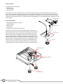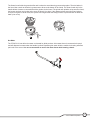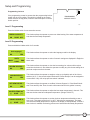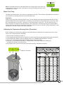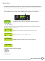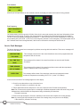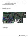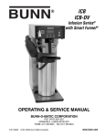
1
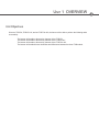
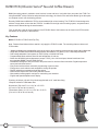
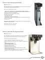
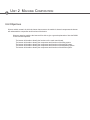
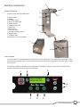
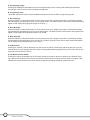
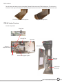
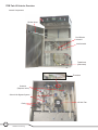
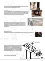
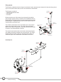
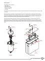
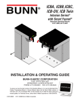
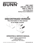
BUNN® TECHNICAL TRAINING
ITCB High Volume
Index
Unit 1: Overview
ITCB-DV
Overview........................................................................................................................ 4
ITCB-DV HV
Overview........................................................................................................................ 5
ITCB-DV HV
Overview........................................................................................................................ 5
Unit 2: Machine Composition
Exterior Overview................................................................................................................ 7
Product Outlets and Removable Parts....................................................................... 7
User Interface................................................................................................................ 7
Interior Overview................................................................................................................. 9
Internal Components Review....................................................................................... 10
Machine Function and Operations..................................................................................... 11
Main Control Board....................................................................................................... 11
Filling System................................................................................................................ 12
Heating System............................................................................................................. 13
Dilution System............................................................................................................. 14
Dispensing System....................................................................................................... 14
Unit 3: Programming
Programming Lockout........................................................................................................ 17
Level 1 Programming.......................................................................................................... 17
Level 2 Programming.......................................................................................................... 17
Calibrating the Sprayhead Flow Rate................................................................................ 19
Calibrating the Bypass Flow Rate...................................................................................... 20
Calibrating the Dilution Flow Rate..................................................................................... 20
Master Tank Temperature................................................................................................... 21
Calibrating the Temperature Probe.................................................................................... 21
Unit 4: Troubleshooting
Service Tools....................................................................................................................... 23
Test Outputs.................................................................................................................. 23
Test Switches................................................................................................................ 24
Test Frequency.............................................................................................................. 24
Service Fault Messages...................................................................................................... 24
Triac Map.............................................................................................................................. 25
Rev. A
© 2011 Bunn-O-Matic Corporation. All Rights Reserved
Unit 1 OVERVIEW
Unit Objectives
Given an ITCB-DV, ITCB-DV HV, and an ITCB Twin HV, the learner will be able to perform the following tasks
successfully:
The learner will be able to discuss key features of the ITCB-DV.
The learner will be able to discuss key features of the ITCB-DV HV.
The learner will be able to discuss key features of the ITCB Twin HV.
The learner will be able discuss similarities and differences between the three ITCB models.
BUNN ITCB (Infusion Series® Tea and Coffee Brewer)
BUNN innovation makes it possible to brew iced tea, hot tea and hot or iced coffee from one model, the ITCB. Featuring BrewWISE® with pre-infusion and pulse brew technology, the Infusion Tea and Coffee Brewer gives the operator complete control over the brewing process.
Recently, BUNN has modified the ITCB to accommodate high volume brewing. The ITCB-DV HV was designed to
achieve a larger brew volume than the ITCB-DV. In addition to the high volume brewing system, components and
features were affected during the transformation.
First, we will take a look at the key features of an ITCB-DV. Most of the features can be found on all ITCB models
and others will be specific to that machine.
Key Features
Model: ITCB-DV & ITCB-DV with Flip Tray
Note: Features listed below with an asterisk* only apply the ITCB-DV model. The remaining features relate to all
ITCB models.
•
•
•
•
•
•
•
•
•
•
•
•
*Models available with integrated flip tray that converts to three positions: thermal carafe, airpot and tea dispenser.
Large tank provides back-to-back brewing capacity and allows 3 or 5 gallon (11.4 to 18.9 litres) tea batches.
Dual voltage adaptable. Can operate at 120V/15 amp or 208-240V/20 amp.
Programmable batch switches allow full and half batches of iced tea.
Brews into all BUNN iced tea dispensers (except T DS-5),1.9 to 3.8 litre airpots, thermal carafes and can
accommodate BUNN ThermoFresh® Servers.
BrewWISE® intelligence with pre-infusion and pulse brew for maximum flavor extraction. Digital temperature
control and cold brew lockout.
Easy Pulse interface allows automatic programming of pulse routine.
Energy-saver mode reduces tank temperature during idle periods.
Display advertising messages and machine status.
Brew counter keeps track of how many batches brewed.
Most models include graphic overlays for customizing user interface.
English and Spanish alphanumeric display.
Plumbing: 20-90 psi (138-621 kPa). Model supplied with a 1⁄4” male flare fitting.
*Requires minimum 1GPM water flow.
Dimensions (Tall): 34.37” H x 11.53” W x 23.78” D
(87.3cm H x 29.3cm W x 60.4cm D)
*Dimensions (Short): 31.12” H x 11.53” W x 23.78” D
(79.1cm H x 29.3m W x 60.4cm D)
4
ITCB-DV HV Training
Infusion Tea and Coffee High Volume Brewer
Model: ITCB-DV HV
Note: Bullet points will only list additional features of the machine when compared
to the preceding model, which is the ITCB-DV.
High Volume Transformation Includes:
• Large 3-gallon (11.36 litre) tank provides back-to-back brewing capacity.
• Brews 5.1 to 11.9 gallons (19.3 to 45 litres) of perfect coffee per hour and 26.7
gallons (10.2 litres) of iced tea per hour.
• Includes both tea and coffee Smart Funnel®.
• Includes hot water bypass.
• Removable front panel.
• Optional side mount for hot water faucet.
• Rail locator for TF Server and TDO-N Dispenser. Invert rails to accommodate regular tea dispensers.
• Tall trunk only.
Plumbing: 20-90 psi (138-621 kPa). Supplied with 3⁄8” male flare fitting. Requires
minimum of 1.5 gpm water flow.
Dimensions: 34.4”H x 10.1”W x 23.8”D
(87.4cm H x 25.7cm W x 60.5cm D)
Infusion Tea and Coffee Twin High Volume Brewer
Model: ITCB Twin HV
Note: Bullet points below will only list additional features of the machine
when compared to the preceding model, which is the ITCB-DV HV.
ITCB Twin HV Transformation Includes:
•
•
•
•
•
•
•
•
•
Large 5.5 gallon tank compared to 3 gallon tank (ITCB).
Brews 18.9 gallons (71.5 litres) per hour compared to 11.9 gallons per hour.
Additional hood fan and thermistor.
Different CBA part number.
Dimensions- Reference Spec Sheet.
Additional relays in hood (d/c).
Additional inlet valve for tank filling.
No Dual Volt option. Requires 3-wires plus ground service rated 120/240V, single phase 60Hz..
20-90 psi (138-621 kPa). Supplied with 3⁄8” male flare fitting. Requires minimum of 2.0 gpm water flow compared to 1.5 gpm.
5
Bunn-O-Matic Corporation
Unit 2 Machine Composition
Unit Objectives
Given a realistic scenario in which the learner has access to the machine’s internal components the learner
will understand the composition and functions of the brewer.
Given an operating machine the learner will be able to give a general explanation of how the BUNN ITCB HV brewer operates.
The learner will be able to identify the functions of the main control board .
The learner will be able to identify the components and functions of the filling system.
The learner will be able to identify the components and functions of the heating system.
The learner will be able to identify the components and functions of the dispensing system.
The learner will be able to identify the components and functions of the dilution system.
C
Machine Composition
A
Exterior Overview
G
Product Outlets and Removable Parts
A. User Interface
B. Display
C. Hot Water Outlet
D. High Lime Sprayhead
E. Dilution Nozzle
F. Funnel Sensing Coil
G. Data Plate
H. Rail Locator
I. Top Cover Vents
J. Optional Hot Water Outlet
K. Bypass Outlet
L. Ventilation Hole
On/off switch (on the right panel)
B
E
J
H
F
I
L
D
K
User Interface
The user interface is a membrane switch adhered to the front of the brewer. The membrane is connected to the
control board by a ribbon cable. The user interface allows the user to select the product, batch size and to begin
the brew cycle.
The machine’s display is mounted to the control board. The display is visible on the front of the machine and
provides information to the user and to the technician.
F
ENABLE
ON / OFF
BREW
A
B
®
READY TO BREW
WATER TEMP: 200°
BREW
A
C
BREW
B
D
FULL
BREW
C
G
HALF
E
7
Bunn-O-Matic Corporation
A. Programming (right)
Pressing and holding this pad allows entry into the programming menus. Pressing and releasing the pad steps
through each function screen while in the programming mode.
B. Programming (left)
This hidden pad can be used to scroll backwards through the function list while in programming mode.
C. Brew A Switch
When the ON/OFF is ON and the brewer is on the main screen (not in programming mode), momentarily pressing
and releasing this pad will begin a brew cycle for regular coffee. The Brew A switch is also used to select options that
appear on the display during programming such as “NO/( - )”.
D. Brew B Switch
When the ON/OFF is ON and the brewer is on the main screen (not in programming mode), momentarily pressing
and releasing this pad will begin a brew cycle for Decaf coffee. The Brew B switch is also used to select options that
appear on the display during programming such as “DONE”.
E. Brew C Switch
When the ON/OFF is ON and the brewer is on the main screen (not in programming mode), momentarily pressing
and releasing this pad will begin a brew cycle for Tea. The Brew C switch is also used to select options that appear
on the display during programming such as “YES/( + )”.
F. On/Off Switch
Pressing the “ON/OFF” pad will alternately turn the brewer on and off. Pressing this pad during the brew cycle will
interrupt the brew cycle, stopping the flow of water. Pressing this pad during programming of the brewer will exit the
setup and return to the main screen.
G. Full Batch Selector Switch
Pressing the switch corresponding to the Full batch selects the maximum amount of product to be brewed. Pressing a different batch switch after a brew cycle has been initiated does not change the brew batch in progress. Light
indicates the selected batch to brew. Also used in programming to adjust settings on both batch sizes.
8
ITCB-DV HV Training
Rail Locators
The rail locators are factory set to accommodate Thermal Fresh servers and TDO-N dispensers. The rails can be
inverted to fit with regular tea dispensers by detaching the screws on the bottom of the brewer that secure the rails.
Regular Tea Dispensers
TF Servers and TDO-N Dispensers
ITCB HV Interior Overview
Internal Components
*Thermistor
120 VAC Fan
Thermistor
Dillution Hose
Solenoid
(Dispense Valve)
CBA
Solenoid for Bypass System
Dual Inlet
Solenoid
*Transformer
(Relocated)
9
Bunn-O-Matic Corporation
ITCB Twin HV Interior Overview
Internal Components
Dillution Hose
Dual Dilution
Solenoid
Inlet Solenoid
Transformer
(Relocated)
Thermistor
Solenoid
(Dispense Valve)
Solenoid for Bypass System
Realy
10
ITCB-DV HV Training
120 VAC Fan
Component Differences Review
Transformer (Relocated)
The purpose of relocating the transformer to the bottom base is to reduce
the amount of heat being produced under the top hood panel. It’s the same
120/12 VAC transformer found in the ITCB-DV HV.
120 VAC Fan
UL requirements state that ambient temperatures under the top hood panel
must not exceed 158°F/70°C. The fan is meant to cool and maintain an operable temperature that is below the UL requirement. The fan is located under
the top panel vents to direct air flow out of the hood and runs
continuously.
Thermistor
The additional thermistor is used to monitor the ambient temperature under the top hood panel. If temperatures exceed 158°F/70°C,
then a display message will show reading “Check Fan”, and all
input/outputs to the control board are shut-down. This allows the
BUNN ITCB HV unit to conform to UL requirements. The thermistor
is located within the liquid level and ground wire harness connector.
If the thermistor ever needs to be replaced, a new liquid level and
ground harness with thermistor will need to be ordered as a service
part replacement.
Note: 1,753 ohm nominal for 70°C/158°F
Relay (ITCB Twin HV)
The additional two relays are used independently to supply voltage to the left or right dilution
valve during a tea brew cycle. The purpose of using relays for the operation of either dilution
valve is to use the existing dc output from the control board that operated the optional funnel
lock valves on a ICB brewer. The relay coils are rated for 120 dc and the supply voltage on the
relay contact is 120 vac for the operation of the dual dilution inlet valve.
Machine Function and Operations
Main Control Board
Control Board
(Mounted Display)
The main control is the brain of the brewer. In the Digital
Brewer Control (DBC®) system, the control board is the
single component that contains all of the programming
software, it interprets all the data it receives from the level
and temperature sensors and activates components to
fulfill those demands. The main control board responds
to the users input through the membrane switch and activates and controls the brew cycle. The control board can
receive data from Smart Funnels® through a sensing coil
on the front of the machine.
In a digital brewer the control board takes the place of
the liquid level control board, the timer board, the dilution
timer and the mechanical thermostat. All of these components are combined into a single unit.
Gasket
Bezel
Membrane Switch
Bunn-O-Matic Corporation
11
Filling System
The fill system maintains the level of water in the brewer’s tank. Anytime water is drawn off of the tank during a brew
cycle or from the hot water outlet, the fill circuit activates to refill the tank.
The fill system consists of:
• 120VAC Solenoid Inlet Valve
• Flow Control
• Fill Probe
To Dilution
Nozzle
Water enters the rear of the brewer from the supply line and first
goes through a plastic strainer mounted in the combination inlet solenoid/dilution solenoid assembly. From the solenoid valve the water
flows through a .75 gallon per minute flow control washer and then
into the bottom of the water tank.
The 120VAC solenoid inlet valve is activated by the control board
anytime the brewer calls for water. The valve opens and allows
water to flow, under line pressure, to the tank where the silicon tube
connects to a fill tube attached to the tank.
To Tank
Inlet Connection
Adapter
Dilution
Solenoid
The control board monitors the level of water in the tank through a
low voltage level probe mounted to the top of the tank. The control
board grounds a 2.5VAC signal to the tank through the water. If it
looses this signal, the control board will activate the inlet valve.
Inlet
Solenoid
ITCB Twin HV
To Dilution
Nozzle
To Dilution
Nozzle
To tank
To Tank
Inlet
Solenoid
Dilution
Solenoid
12
ITCB-DV HV Training
.50 GPM
Flow Control
Tube
Clamp
.750 GPM
Flow Control
.50 GPM
Flow Control
Heating System
The heating system consists of:
• Water Tank
• Heating Elements
• High-limit Thermostat
• Temperature Sensor
• DV Switch
The heating circuit maintains the water in the tank at a preset temperature this ensures that the water is always ready
for brewing.
Water for brewing is contained in a 3 gallon stainless steel tank. This tank contains a 1680W @ 120VAC heating
element that is powered by the line voltage into the machine. The heating element is controlled by the control board
through a mechanical relay. The dual voltage ITCB-DV HV brewer adds an additional 2268W for 208/240VAC application; the two elements are wired in series when selected for 208/240VAC.
The control board monitors the water in the tank by a temperature sensor that is in contact with the water. This
temperature sensor is a digital thermistor; the control board reads the temperature as value of resistance. The temperature sensor allows the control board to trigger the heating element triac when the temperature drops below its
programmed value and shut down the trigger voltage when the water temperature reaches the programmed holding
value.
Temperature
Sensing Probe
Temperature
Sensing Probe
Liquid Level
Probe
Liquid Level
Probe
Heating
Elements
Heating
Elements
High Limit
Thermostat
High Limit
Thermostat
Water Tank
Water Tank
ITCB HV
ITCB Twin HV
13
Bunn-O-Matic Corporation
Dilution System
The dilution system consists of:
• Dilution Valve
• .50 Flow Control
• Dilution Nozzle
The ITCB-DV HV can be programmed for quick brewing (without delay) or programmed with a dilution delay time
under tea recipes. After or during the dispense of concentrate into the receiving vessel, the brewer will activate the
dilute valve to begin the diluting process for the tea concentrate. The dilution valve is rated 120VAC and is mounted
on the same body as the inlet valve. The dilution water is regulated with a .50 flow washer before it dispenses out the
dilution nozzle.
Bypass Solenoid
Dispensing System
•
•
•
•
•
The dispensing system consists of:
Dispense Valve
By-pass Valve
Sprayhead
Smart Funnel®/Pouch Pack Tea Funnel
Dispense Solenoid
The ITCB-DV HV brewer is a gravity brewing system. This process
uses the head pressure in the hot water tank to allow the water to flow
from the tank once a valve is opened. For coffee brewing, the ITCBDV HV uses two valves; a dispense valve and a by-pass valve. Both
valves are activated by the CBA for a set time in order to achieve the
desired volume of water or by-pass percentage. The dispense valve is
rated at 120VAC. The brewing water flows out of the sprayhead on the
end of the valve. The sprayhead not only serves to diffuse the water
over the product but also serves as the outlet flow control; any sprayhead change will increase or decrease the volume of finished product.
Sprayhead Outlet
Sprayhead
Dispense Solenoid
4
3
Bypass Solenoid
Sprayhead
14
ITCB-DV HV Training
The Smart funnel holds the ground coffee and is where the actual brewing process takes place. The wire basket in
the funnel has a notch to allow the by-pass water to divert to the bottom of the funnel. The Smart funnel chip in the
handle allows a brewer to communicate with a grinder via the funnel. The grinder will upload a recipe onto the funnel;
the brewer can then receive that recipe once the funnel is in place. If the operator places a tea funnel and selects
a recipe for regular or decaf coffee, the system will recognize that the wrong funnel is in place and will not brew the
batch (vice versa).
Hot Water
The ITCB-DV HV can deliver hot water on-demand for allied products. A hot water faucet is connected to the tank
and will dispense hot water when the handle is pulled. Dispensing hot water while the machine is brewing will affect
pot levels in the server. It is not recommended to use the hot water faucet while brewing a batch.
15
Bunn-O-Matic Corporation
Unit 3 Programming
Unit Objectives
Given an installed BUNN ITCB HV brewer, the learner will be able to complete the following tasks successfully.
The learner will be able to access and scroll through the programming options.
The learner will be able to perform calibrations using the programming options.
UNLOCK
Setup and Programming
LOCK
Programming Lockout
MEMORY
If the programming cannot be access then the programming lockout
switch is in the Lock position. The switch is located on the control
board. Remove the top panel, locate the switch and place it into the
Unlock position.
PROGRAMMING
LOCKOUT SWITCH
P3048
Level 1 Programming
Press the hidden switch for one second to access.
BREW LOCKOUT ?
ON
DONE OFF
This function allows the operator to prevent or allow brewing if the water temperature is
less than the Set Ready temperature.
Level 2 Programming
Press and hold the hidden switch for 5 seconds
Set Language?
NO
YES
UNITS
Metric
DONE
ENG
REVIEW RECIPES ?
NO
YES
ASSIGN RECIPE ?
NO
YES
SET NEW RECIPE ?
NO
YES
MASTER TEMP 200O
(-)
DONE
(+)
READY DEGREE 5O
(-)
DONE
(+)
This function allows the operator to select the language used for the display.
This function allows the operator to select if numeric settings are displayed in English or
Metric units.
This function allows the operator to view the brew settings for various coffee recipes
stored into the brewer. It also allows the operator to modify any of the brew settings for a
particular recipe stored in the brewer.
This function allows the operator to assign a recipe to (or disable) each of the 3 brew
switches (A, B, C). Any saved recipes listed under “Review Recipes” can be assigned to
a brew switch. Only one recipe per brew switch is allowed.
This function allows the operator to set Brew Volumes, Bypass %, Pulse Brew/Preinfusion Times and Drip Out Times for each coffee name stored in the grinder’s memory.
This function allows the operator to adjust the brew water temperature in the tank. This
also sets the hot water faucet dispense temperature. (Range 150-207°F)
This function allows the operator to set the minimum temperature allowable to start a
brew cycle. The range can be from 2° to 20° F below the set temperature. The water
must be at the Ready temperature or higher for the display to indicate Ready To Brew. If
brew lockout is enabled, the brewing process won’t start below this Ready temperature.
17
Bunn-O-Matic Corporation
ENABLE ADS ?
NO
DONE
YES
ENABLE SANITATION
NO
DONE
YES
This function allows the operator to enable the sanitation function and set the time before a cleaning alert will be displayed.
ENABL ENERGYSAVR
NO
DONE YES
This function allows the operator to enable the Energy Savings mode function and set
the idle time. Once the set idle time has expired, the operator can choose to have the
heaters either turn off, or reduce the tank holding temp to 140° F (60° C).
ENABLE FRESH TIMER
DONE
YES
NO
This function allows the operator to enable the Freshness Alert and set the expiration
time. The fresh time is the amount of time the product is allowed to sit in the server/dispenser before a batch is considered expired.
XX
REFILL
(-)
DONE
XXX
(+)
SPRAY OZ/M: XX.X
(-)
This function allows the operator to choose whether or not to display an advertising message. An ad can be saved to the brewer by either writing the ad using the programming
commands, or by entering the ad into the brewer using an Ad Card. This message will
be displayed when the brewer is not in use.
DONE
(+)
BYPS OZ/M: XX.X
(-)
DONE
(+)
DILUTE OZ/M: XX.X
(-)
DONE
(+)
CALIBRATE FLOW?
NO
YES
BREW COUNTERS?
NO
YES
SET RECIPES TEMPS
NO
YES
ENTER ASSET #
NO
YES
18
ITCB-DV HV Training
This function allows the operator to adjust the sensitivity of the refill circuit. This is mainly a troubleshooting feature. Water in different geographical locations can have different
conductivities. By adjusting the sensitivity of the refill circuit, this will allow the brewer to
operate under various water conditions.
This function allows the operator to view or enter the actual flow rate coming out of the
sprayhead. This is Not used to control the actual flow rate, but to tell the internal processor how fast the water is flowing.
This function allows the operator to view or enter the actual flow rate coming out of the bypass valve. This is Not used to control the actual flow rate, but to tell the internal
processor how fast the water is flowing.
This function allows the operator to view or to enter the actual flow rate coming out of
the dilution nozzle. This is not used to control the actual flow rate, but to tell the internal
processor how fast the water is flowing.
This function allows the operator to test and enter the actual flow rate of the
sprayhead(s) and the bypass/dilution for each side of the brewer by dispensing each
separately for one minute. The volumes are then entered into the brewer.
This function allows the operator to track the total number of brew cycles completed, as
well as the number of batches brewed using each of the brew buttons. There are (up to)
three resettable counters, and one life counter that is not resettable.
This function allows the operator to set separate temperatures for each selected recipe.
This function allows the operator to enter the machine’s asset number. This can be useful for tracking the usage or service of an individual machine within a group.
FUNNEL DETECT?
BREW ALERT?
NO
NO
DONE
DONE
YES
YES
ENTER SERVICE #
NO
YES
SERVICE TOOLS
NO
YES
FACTORY DEFAULTS
NO
YES
Sets the inability to initiate a brew cycle if the funnel is not properly inserted into the
funnel rails.
By selecting yes to this option, a message will display alerting the operator that the machine is currently in a brew process. If enabled, the message will only display while the machine is brewing.
This function allows the operator to enter in the telephone number to call if service is
needed. The service number will be displayed anytime there is a fault message displayed.
(For Authorized Service Personnel Only)
This function allows the testing of individual components and the ability to check switches for proper function. This function also tests the funnel sensor coil’s frequency (diagnostic tool for troubleshooting purposes only).
Refer to Service Manual for in depth procedures.
This function allows the operator to erase all of the previously entered recipes and ad
messages. Factory-set default values will replace All previous settings.
CALIBRATE FLOW?
Calibrating the Sprayhead Flow Rate
Step 1: Place a measuring container with a minimum capacity of 60 ounces
beneath the funnel of the brewer. Water can also be dispensed into the server and
then into the measuring container.
Step 2: Press and hold the right hidden switch to enter level 2 programming.
Continue to press the right hidden switch until the display reads “Calibrate Flow?”.
NO
YES
SPRAYHEAD CAL
NO
YES
CONTAINER READY?
QUIT
YES
Step 3: Press YES to advance to the “Spray Head Cal?” function screen.
Step 4: Press YES. The display will read “Container Ready?” If the container is
under the funnel, press YES. The display will read “Calibrate Spray…Press Brew to
Start”.
Step 5: Press and release the BREW switch. The display will read “Calibrate
Spray…60 Sec to Finish”. The 60 second timer on the display will count down to
zero. When the counter reaches zero, the display will change to OZ, along with the
existing ounces per minute.
CALIBRATE SPRAY
QUIT
START
CALIBRATE SPRAY
60 SEC TO FINISH
Step 6: Measure the amount of water in the container and using the (-) or (+),
adjust the amount on the display to match the amount in the container. Then press
DONE.
SPRAYHD OZ XX.X
Step 7: The display should now read “New Spray Flow” along with the correct flow
rate of the sprayhead in ounces per minute. After 5 seconds, the display will return
to the “Calibrate Flow?” screen.
NEW SPRAY FLOW
(-)
DONE
(+)
XX.X OZM
5 sec
CALIBRATE FLOW?
NO
YES
19
Bunn-O-Matic Corporation
Calibrating the Bypass Flow Rate
Step 1: Place the measuring container with a minimum capacity of 60 ounces beneath
the funnel of the brewer.
Water can also be dispensed into the server and then into the measuring container.
Step 2: Press and hold the right hidden switch to enter level 2 programming. Continue
to press the right hidden switch until the display reads CALIBRATE FLOW ?.
CALIBRATE FLOW?
NO
YES
SPRAYHEAD CAL
NO
YES
BYPASS CAL?
NO
Step 3: Press and release YES to advance to the SPRAYHEAD CAL? function screen.
Step 4: Press and release NO to advance to the BYPASS CALIBRATION screen.
Step 5: Press YES. The display will read CONTAINER READY? If the container is
under the funnel, press YES. The display should read CALIBRATE BYPASS .. PRESS
BREW TO START.
Step 6: Press and release the BREW switch. The display will read CALIBRATE
BYPASS...60 SEC TO FINISH. The 60 second timer on the display will count down to
zero. When the counter reaches zero, the display will change to BYPASS OZ/M, along
with the existing ounces per minute.
Step 7: Measure the amount of water in the container and using the (-) or (+), adjust
the amount on the display to match the amount in the container. Then press DONE.
Step 8: The display should now read: NEW BYPASS FLOW, along with the correct
flow rate of the bypass in ounces per minute. After about 5 seconds, the display will
return to the CALIBRATE FLOW screen
Calibrating the Dilution Flow Rate
Step 1: Place the measuring container with a minimum capacity of 130 ounces beneath the dilution nozzle on the brewer. Water can also be dispensed into the server and then into the measuring
container.
Step 2: Press and hold the right hidden switch to enter level 2 programming. Continue to press the
right hidden switch until the display reads “Calibrate Flow?”.
Step 3: Press and release YES to advance to the “Sprayhead Cal?” function screen.
Step 4: Press and release NO to advance to the “Bypass Cal?” function screen.
YES
CONTAINER READY?
QUIT
YES
CALIBRATE BYPASS
QUIT
START
CALIBRATE BYPASS
60 SEC TO FINISH
BYPS OZ XX.X
(-)
DONE
(+)
NEW BYPS FLOW
XX.X OZM
5 sec
CALIBRATE FLOW?
NO
YES
CALIBRATE FLOW?
NO
YES
SPRAYHEAD CAL
NO
YES
BYPASS CAL?
NO
YES
DILUTION CAL?
QUIT
YES
Step 4: Press and release NO to advance to the “Dilution Calibration” screen.
Step 5: Press YES. The display will read “Container Ready?” If the container is under the nozzle,
press YES. The display should read “Calibrate Dilute .. Press Brew to Start”.
Step 6: Press and release the BREW switch. The display will read “Calibrate Dilute.... 60 Sec to
Finish”. The 60 second timer on the display will count down to zero. When the counter reaches zero,
the display will change to “Dilute OZ/M” along with the existing ounces per minute.
Step 7: Measure the amount of water in the container and using the (-) or (+), adjust the
amount on the display to match the amount in the container. Then press DONE.
CONTAINER READY?
QUIT
YES
CALIBRATE DILUTE
QUIT
START
CALIBRATE DILUTE
60 SEC TO FINISH
DILUTE OZ XX.X
(-)
20
DONE
(+)
NEW DILUTE FLOW
ITCB-DV HV Training
XX.X OZM
5 sec
DILUTE OZ XX.X
(-)
DONE
(+)
NEW DILUTE FLOW
Step 8: The display should now read “New Dilute Flow” along with the correct flow rate
of the bypass in ounces per minute. After about 5 seconds, the display will return to the
“Calibrate Flow?” screen.
XX.X OZM
5 sec
CALIBRATE FLOW?
NO
YES
Master Tank Temp
The Master tank temperature is the maximum temperature for the tank. The Set Recipe Temps allows the operator to
set temperature for all recipes and will override the Master temp.
Explanation:
Setting recipe temps will override the Master Temp. The tank will hold at the lowest temperature between the three
selected recipes stored in the brew buttons. For instance, let’s say Brew A’s recipe temperature is set at 205°, Brew
B’s recipe temperature is set at 205°, and Brew C’s recipe temperature is set at 200°. The tank will hold at 200°. If
Brew A or Brew B is pressed, the tank will heat to the 205° temperature. The brew button must be pressed again in
order for a brew to start. After the completion of that brew, the tank will return to the 200° holding temperature. It may
take awhile for the tank to return to the lower temperature.
Calibrating the Temperature Sensing Probe (Thermistor)
NOTE: Variables such as tank set temperature could show different numbers than the example shown here. Tank
must be at it’s ready temp before calibrating.
1. Remove silicon vent fitting from tank lid.
2. Insert a digital temp probe through the exposed vent hole in tank lid to the same depth as the factory temp probe.
3. Press and hold the “Hidden” button until display reads “CAL TEMPERATURE SENSOR?” “NO/YES”
4. Select “YES”. The display should show something similar to the screen below.
5. Press the + (Control) button to increase or - (Digital) button to decrease temperature reading until
it matches the reading on the thermometer.
6. Exit program mode, remove thermometer, and install vent fitting. Calibration is complete.
200° CAL
(-)
DONE
200°
(+)
Adjust This
Adjust
this Number
number
200° CAL
(-)
DONE
200°
(+)
Adjust this
number
21
Bunn-O-Matic Corporation
Unit 3 Troubleshooting
Unit Objectives
Given a realistic scenario depicting a broken machine, the learner will be able to effectively troubleshoot,
diagnosis, and repair the problem returning the machine to normal operation.
Given a machine displaying an error message, all the necessary tools and safety equipment, the learner will be able to diagnosis the problem.
Given a list of error messages and issues, the learner will be to identify the probable cause of the message or issue.
Service Tools
Like all digital brewers that BUNN manufactures, the ITCB-DV HV brewer features on-board troubleshooting. Since
all of the machine’s components are controlled or activated by the control board you can activate and test components individually from the user interface. This allows you to listen to solenoid valves opening, observing the flow of
water or test to see if a component is receiving voltage using a meter.
The Service Tools option is located in Level 2 of the programming. Enter level 2 programming by pressing and holding the right hidden switch for 5 seconds. Use the right hidden switch to scroll to the Service Tools Screen.
Hidden
Switch
Right
Hidden
Switch
®
®
ENABLE
ENABLE
ON//OFF
OFF
ON
BREW
BREW
FULL
BREW
BREW
AA
BREW
BREW
BB
BREW
BREW
CC
HALF
SERVICE TOOLS
NO
BREW
A
Press the Brew C button to select Yes. This will enter the Service Tools feature.
YES
BREW
B
BREW
C
In the Service Tools selection there are 3 screens available, by selecting Yes, you will enter that test function, by
selecting NO you will move to the next test.
TEST OUTPUTS?
NO
YES
TEST SWITCHES?
NO
YES
TEST FREQUENCY?
NO
YES
Outputs- Test Outputs supplies voltage to load components in the brewer
Switches- Tests the inputs from the membrane switch
Frequency- Indicates the transmit frequency of the funnel sensing coil
Test Outputs
TEST OUTPUTS?
NO
YES
The following components can be tested individually:
• Brew valve
• Dilution valve
• Bypass Valve
• Refill valve
• Tank heater triac
• Tank Heater Relay
23
Bunn-O-Matic Corporation
Test Switches
TEST SWITCHES?
NO
YES
Rightdisplay
Hidden Switch
Press any of the input buttons on the membrane switch, the
will show which button is being pressed.
®
®
ENABLE
ENABLE
ON//OFF
OFF
ON
BREW
BREW
FULL
BREW
BREW
AA
BREW
BREW
BB
BREW
BREW
CC
HALF
Test Frequency
TEST FREQUENCY?
NO
YES
The funnel sensing circuit is tuned to 125 kHz. If the circuit is not tuned correctly, then the funnel information will not
be transferred to the brewer. Therefore, the microprocessor is constantly fine tuning to get as close as possible to
125 kHz. It has eight possible tuning steps numbered 0 - 7. When you look at the “TEST FREQUENCY” screen you
see something like (124.7 KHZ .5) The 124.7 is the frequency, and the 5 is the tuning step. The decimal point next to
the 5 indicates the funnel is being detected; if the funnel is removed the decimal point should turn off.
Service Fault Messages
The brewer features several error messages for problems occurring within the machine. These error messages will
show up on the display.
HEATING TIME
TOO LONG
FILL TIME TOO
LONG
TEMP SENSOR
OUT OF RANGE
CHECK FAN
This message will be shown if the control board does not see the programmed water
temperature with 60 minutes.
This message will be shown if the control board does not see the tank fill within
30 minutes.
This message will be shown if the control board loses contact with the temperature
sensor or senses a short in the connection.
This message will be shown if the thermistor under the top hood panel senses
ambient air temperatures exceeding 158°F/70°C. ( below 1,753 Ohms)
In the event that a Check Fan message appears on the display:
1. Check for any obstructions on top of the hood vent.
- If hood vent checks ok, proceed to next step.
2. Take a digital thermometer and place it in one of the top hood vents. Record the temperature.
Note: Do not remove the top hood prior to recording the ambient temperature within the hood. Doing so will dissipate heat, which will affect the temperature being monitored by the thermistor.
- Proceed to next step.
24
3. Remove the top hood panel. Check the 120VAC fan and ensure this component is working properly.
Note: by removing the top hood panel, the Check Fan message may or may not be on the display.
- If fan checks ok, proceed to next step.
ITCB-DV HV Training
4. Check the ohms value of the thermistor located within the liquid level and ground wire harness connector. - If Check Fan message persists during operation, then you may have a defected thermistor or the
machine is placed in a high ambient environment. Example: Machine is placed too close to equipment that is producing heat such as flood lights, ovens, ect.
*An example of normal operating temperatures would be:
60°C/140°F under the top hood. Thermistor ohms value reading 2,488.
Triac Map ITCB-DV HV (Hardee’s)
1
2
3
4
1. Dilution Valve (TH8)
2. Bypass Valve (TH7)
3. Dispense Valve (TH5)
4. Inlet Valve (TH2)
25
Bunn-O-Matic Corporation
Triac Map (ITCB HV Twin)
8
7
6
5
3
4
1. Left Relay (Dilution) (TH1)
2. Inlet Valve (TH2)
3. Right Relay (Dilution) (TH3)
4. Heating Circuit (TH4)
5. Left Dispense Valve (TH5)
6. Right Dispense Valve (TH6)
7. Left Bypass Valve (TH7)
8. Right Bypass Valve (TH8)
26
ITCB-DV HV Training
2
1