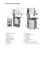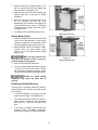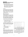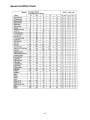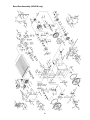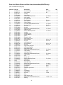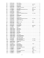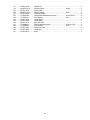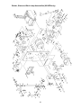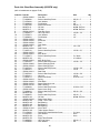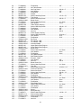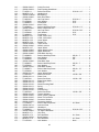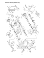
1
This Manual is Bookmarked
Operating Instructions and Parts Manual
14- & 20-inch Metalworking Band Saws
Models 8014FW and 8020FW
Model 8014FW
Model 8020FW
WMH TOOL GROUP
2420 Vantage Drive
Elgin, Illinois 60123
Ph.: 800-274-6848
www.wmhtoolgroup.com
Part No. M-8014FW
Revision A 6/05
Copyright © WMH Tool Group
This manual has been prepared for the owner and operators of a Wilton 8014FW or 8020FW Band Saw.
Its purpose, aside from machine operation, is to promote safety using accepted operating and
maintenance procedures. To obtain maximum life and efficiency from your band saw and to aid in using it
safely, please read this manual thoroughly and follow the instructions carefully.
Warranty and Service
WMH Tool Group warrants every product it sells. If one of our tools needs service or repair, one of our
Authorized Repair Stations located throughout the United States can provide quick service or information.
In most cases, a WMH Tool Group Repair Station can assist in authorizing repair work, obtaining parts, or
perform routine or major maintenance repair on your Wilton product.
For the name of an Authorized Repair Station in your area, please call 1-800-274-6848, or visit our web
site at www.wmhtoolgroup.com
More Information
Remember, WMH Tool Group is consistently adding new products to the line. For complete, up-to-date
product information, check with your local WMH Tool Group distributor, or visit our web site at
www.wmhtoolgroup.com
WMH Tool Group Warranty
WMH Tool Group makes every effort to assure that its products meet high quality and durability standards
and warrants to the original retail consumer/purchaser of our products that each product be free from
defects in materials and workmanship as follows: 1 YEAR LIMITED WARRANTY ON ALL PRODUCTS
UNLESS SPECIFIED OTHERWISE. This Warranty does not apply to defects due directly or indirectly to
misuse, abuse, negligence or accidents, normal wear-and-tear, repair or alterations outside our facilities,
or to a lack of maintenance.
WMH TOOL GROUP LIMITS ALL IMPLIED WARRANTIES TO THE PERIOD SPECIFIED ABOVE,
BEGINNING FROM THE DATE THE PRODUCT WAS PURCHASED AT RETAIL. EXCEPT AS STATED
HEREIN, ANY IMPLIED WARRANTIES OR MERCHANTABILITY AND FITNESS ARE EXCLUDED.
SOME STATES DO NOT ALLOW LIMITATIONS ON HOW LONG THE IMPLIED WARRANTY LASTS,
SO THE ABOVE LIMITATION MAY NOT APPLY TO YOU. IN NO EVENT SHALL WMH TOOL GROUP
BE LIABLE FOR DEATH, INJURIES TO PERSONS OR PROPERTY, OR FOR INCIDENTAL,
CONTINGENT, SPECIAL, OR CONSEQUENTIAL DAMAGES ARISING FROM THE USE OF OUR
PRODUCTS. SOME STATES DO NOT ALLOW THE EXCLUSION OR LIMITATION OF INCIDENTAL
OR CONSEQUENTIAL DAMAGES, SO THE ABOVE LIMITATION OR EXCLUSION MAY NOT APPLY
TO YOU.
To take advantage of this warranty, the product or part must be returned for examination, postage
prepaid, to an Authorized Repair Station designated by our office. Proof of purchase date and an
explanation of the complaint must accompany the merchandise. If our inspection discloses a defect, we
will either repair or replace the product at our discretion, or refund the purchase price if we cannot readily
and quickly provide a repair or replacement. We will return the repaired product or replacement at WMH
Tool Group’s expense, but if it is determined there is no defect, or that the defect resulted from causes
not within the scope of WMH Tool Group’s warranty, then the user must bear the cost of storing and
returning the product. This warranty gives you specific legal rights; you may also have other rights, which
vary from state to state.
WMH Tool Group sells through distributors only. Members of the WMH Tool Group reserve the right to
effect at any time, without prior notice, alterations to parts, fittings and accessory equipment, which they
may deem necessary for any reason whatsoever.
2
Table of Contents
Warranty and Service ..............................................................................................................................2
Table of Contents ....................................................................................................................................3
Warning...................................................................................................................................................4
Introduction..............................................................................................................................................6
Specifications ..........................................................................................................................................6
Features and Terminology .......................................................................................................................7
Unpacking ...............................................................................................................................................8
Contents of the Shipping Container ......................................................................................................8
Installation and Assembly ........................................................................................................................9
Fence...................................................................................................................................................9
Shear ...................................................................................................................................................9
Grounding Instructions.............................................................................................................................9
Test Run ............................................................................................................................................10
Extension cords..................................................................................................................................10
Adjustments...........................................................................................................................................11
Blade Removal and Installation ..........................................................................................................11
Guide Post .........................................................................................................................................11
Blade Tension ....................................................................................................................................11
Blade Tracking ...................................................................................................................................12
Blade Guides .....................................................................................................................................12
Squaring Work Table with Blade.........................................................................................................13
Replacing Drive Belts .........................................................................................................................14
Work Lamp Bulb.................................................................................................................................14
Band Saw Operation..............................................................................................................................14
Blade Break-In Procedure ..................................................................................................................14
Setting Blade Speed...........................................................................................................................15
Evaluating Cutting Efficiency ..............................................................................................................15
Welder Operation...................................................................................................................................16
Shearing ............................................................................................................................................16
Removing Teeth.................................................................................................................................16
Welding..............................................................................................................................................16
Annealing...........................................................................................................................................17
Blade Selection......................................................................................................................................19
Width .................................................................................................................................................19
Gage..................................................................................................................................................20
Pitch...................................................................................................................................................20
Shape ................................................................................................................................................20
Set .....................................................................................................................................................21
Material ..............................................................................................................................................21
Blade Breakage..................................................................................................................................21
Speed and Pitch Chart...........................................................................................................................23
Typical Band Saw Operations ................................................................................................................24
Troubleshooting – Mechanical and Electrical Problems ..........................................................................26
Replacement Parts ................................................................................................................................29
Parts List: Band Saw Assembly (8014FW only) ..................................................................................30
Band Saw Assembly (8014FW only)...................................................................................................35
Parts List: Welder, Shear and Work Lamp Assemblies (8014FW only)................................................36
Welder, Shear and Work Lamp Assemblies (8014FW only) ................................................................39
Parts List: Band Saw Assembly (8020FW only) ..................................................................................40
Band Saw Assembly (8020FW only)...................................................................................................47
Band Saw Assembly (8020FW only)...................................................................................................48
Parts List: Welder, Shear and Work Lamp Assemblies (8020FW only)................................................49
Welder, Shear and Work Lamp Assemblies (8020FW only) ................................................................52
Electrical Connections – Model 8014FW only.........................................................................................53
Electrical Connections – Model 8020FW only.........................................................................................54
3
Warning
1. Read and understand the entire owners manual before attempting assembly or operation.
2. Read and understand the warnings posted on the machine and in this manual. Failure to comply with
all of these warnings may cause serious injury.
3. Replace the warning labels if they become obscured or removed.
4. This band saw is designed and intended for use by properly trained and experienced personnel only.
If you are not familiar with the proper and safe operation of a band saw, do not use until proper
training and knowledge have been obtained.
5. Do not use this band saw for other than its intended use. If used for other purposes, WMH Tool
Group disclaims any real or implied warranty and holds itself harmless from any injury that may result
from that use.
6. Always wear approved safety glasses/face shields while using this band saw. Everyday eyeglasses
only have impact resistant lenses; they are not safety glasses.
7. Before operating this band saw, remove tie, rings, watches and other jewelry, and roll sleeves up past
the elbows. Remove all loose clothing and confine long hair. Non-slip footwear or anti-skid floor strips
are recommended. Do not wear gloves.
8. Wear ear protectors (plugs or muffs) during extended periods of operation.
9. Some dust created by power sanding, sawing, grinding, drilling and other construction activities
contain chemicals known to cause cancer, birth defects or other reproductive harm. Some examples
of these chemicals are:
•
Lead from lead based paint.
•
•
Crystalline silica from bricks, cement and other masonry products.
Arsenic and chromium from chemically treated lumber.
Your risk of exposure varies, depending on how often you do this type of work. To reduce your
exposure to these chemicals, work in a well-ventilated area and work with approved safety
equipment, such as face or dust masks that are specifically designed to filter out microscopic
particles.
10. Do not operate this machine while tired or under the influence of drugs, alcohol or any medication.
11. Make certain the switch is in the OFF position before connecting the machine to the power supply.
12. Make certain the machine is properly grounded.
13. Make all machine adjustments or maintenance with the machine unplugged from the power source.
14. Remove adjusting keys and wrenches. Form a habit of checking to see that keys and adjusting
wrenches are removed from the machine before turning it on.
15. Keep safety guards in place at all times when the machine is in use. If removed for maintenance
purposes, use extreme caution and replace the guards immediately.
16. Check damaged parts. Before further use of the machine, a guard or other part that is damaged
should be carefully checked to determine that it will operate properly and perform its intended
function. Check for alignment of moving parts, binding of moving parts, breakage of parts, mounting
and any other conditions that may affect its operation. A guard or other part that is damaged should
be properly repaired or replaced.
17. Provide for adequate space surrounding work area and non-glare, overhead lighting.
18. Keep the floor around the machine clean and free of scrap material, oil and grease.
19. Keep visitors a safe distance from the work area. Keep children away.
20. Make your workshop child proof with padlocks, master switches or by removing starter keys.
4
blahblahblah
21. Give your work undivided attention. Looking around, carrying on a conversation and “horse-play” are
careless acts that can result in serious injury.
22. Maintain a balanced stance at all times so that you do not fall or lean against the blade or other
moving parts. Do not overreach or use excessive force to perform any machine operation.
23. Use the right tool at the correct speed and feed rate. Do not force a tool or attachment to do a job for
which it was not designed. The right tool will do the job better and safer.
24. Use recommended accessories; improper accessories may be hazardous.
25. Maintain tools with care. Keep blades sharp and clean for the best and safest performance. Follow
instructions for lubricating and changing accessories.
26. Turn off the machine before cleaning. Use a brush or compressed air to remove chips or debris — do
not use your hands.
27. Do not stand on the machine. Serious injury could occur if the machine tips over.
28. Never leave the machine running unattended. Turn the power off and do not leave the machine until
the blade comes to a complete stop.
29. Remove loose items and unnecessary work pieces from the area before starting the machine.
30. Never place hands directly in line with the saw blade.
31. Always use push sticks when cutting small material.
32. Raise or lower the blade guide only when the machine has been turned off and the blade has stopped
moving.
33. Always wear leather gloves when handling saw blades. The operator should not wear gloves when
operating the machine.
34. Do not allow the saw blade to rest against the workpiece when the saw is not running.
35. The saw must be stopped and the electrical supply must be cut off before any blade replacement,
drive belt replacement, or any periodic service or maintenance is performed on the machine.
36. Remove cut off pieces carefully, keeping hands away from the blade. The saw must be stopped and
the electrical supply cut off or machine unplugged before reaching into the cutting area.
Familiarize yourself with the following safety notices used in this manual:
This means that if precautions are not heeded, it may result in minor injury and/or
possible machine damage.
This means that if precautions are not heeded, it may result in serious injury or possibly
even death.
- - SAVE THESE INSTRUCTIONS - -
5
Introduction
This manual is provided by WMH Tool Group covering the safe operation and maintenance procedures
for a Wilton Model 8014FW or 8020FW Band Saw. This manual contains instructions on installation,
safety precautions, general operating procedures, maintenance instructions and parts breakdown. This
machine has been designed and constructed to provide years of trouble free operation if used in
accordance with instructions set forth in this manual. If there are any questions or comments, please
contact either your local supplier or WMH Tool Group. WMH Tool Group can also be reached at our web
site: www.wmhtoolgroup.com.
Specifications
Model Number ............................................................ 8014FW....................................................8020FW
Stock Number (220V) .............................................. 8014FW-2.................................................8020FW-2
Stock Number (440V) .............................................. 8014FW-4.................................................8020FW-4
Blade Speeds (SFPM) .................................................. 82-330 ...................... Low 65-555, High 390-3280
Height Capacity, Maximum (in.) ............................................. 8............................................................. 12
Throat Capacity, Maximum (in.) ........................................... 14............................................................. 20
Table Size (L x W)(in.) ..................................................20 x 20............................................... 24 x 22-1/2
Table Height at 90° (in.) ....................................................... 39....................................................... 39-1/2
Table Tilt (deg.) ..............................8 fwd/back, 12 left, 15 right....................... 8 fwd/back, 15 left, 15 right
Welder (KVA)...................................................................... 1.5............................................................ 4.2
Blade Length, approx. (in.)................................................. 114 .................................... 150-1/2 to 156-1/2
Blade Width (in.) ...........................................1/8 min., 1/2 max...................................... 1/8 min., 1/2 max.
Motor........................................................................ 1HP, 3Ph.................................................. 2HP, 3Ph
Floor Space Required (in.) ............................................34 x 24..................................................... 42 x 29
Net Weight (lbs.)................................................................ 580 ......................................................... 1210
The above specifications were current at the time this manual was published, but because of our policy of
continuous improvement, WMH Tool Group reserves the right to change specifications at any time and
without prior notice, without incurring obligations.
6
Features and Terminology
1 – Variable Speed Handwheel
2 – Fence
3 – Work Lamp
4 – Chip Blower Hose
5 – Guide Post Lock Knob
6 – Tension Handwheel
7 – Speed and Pitch Selector
8 – Upper Door
9 – Digital Readout
10 – On/Off Buttons
11 – Shear
12 – Lower Door
13 – Pressure Selector Switch
14 – Anneal Button
15 – Weld Button
16 – Welder Clamp
17 – Clamp Handle
18 – Grinder Toggle Switch
19 – Grinder
20 – Gear Selector Lever (8020FW only)
21 – Post Elevating Handwheel (8020FW only)
7
Contents of the Shipping Container
Unpacking
1
1
1
1
1
1
1
1
1
Open shipping container and check for shipping
damage. Smaller parts are found in a separate
box at the foot of the band saw. Report any
damage immediately to your distributor and
shipping agent. Do not discard any shipping
material until the Band Saw is set up and
running properly.
Compare the contents of your container with the
following parts list to make sure all parts are
intact. Missing parts, if any, should be reported
to your distributor. Read the instruction manual
thoroughly for assembly, maintenance and
safety instructions.
Band Saw
Fence
Knob
Shear
Eye Bolt
Set of Hex Wrenches (3, 6, 8 and 10 mm)
Set of Keys (Model 8020FW only)
Owner's Manual
Warranty Card
Read and understand the entire contents of this manual before attempting set-up
or operation! Failure to comply may cause serious injury.
8
Installation and Assembly
Tools required for assembly:
Forklift or hoist with strap or chain
Set of hex wrenches (provided)
Remove all crating and plastic from around the
band saw. Remove any lag screws or holding
straps which secure the saw to the wood pallet.
Remove the eye bolt from the tool box, and
screw it into the hole at the top of the machine.
Lift the band saw from the pallet using a strap or
chain connected to the eye bolt.
Move the band saw to its permanent location
which should be dry, well ventilated, with
sufficient lighting. Leave enough space on all
sides to handle long stock or perform routine
maintenance on the machine. Make sure the
floor is level and able to support the weight of
the machine.
The Band Saw may be further stabilized by
securing it to the floor using lag screws (not
provided) through the tabs at the bottom.
Areas of the Band Saw have been given a
protective coating at the factory. This should be
removed with a soft cloth moistened with
kerosene or a mild cleaner/degreaser. Do not
use gasoline, paint thinner, or lacquer thinner as
these will damage painted surfaces. Do not use
an abrasive pad.
Fence
Place the fence (Figure 1) onto the groove in the
table as shown, and screw in the knob to tighten
the fence in position.
Figure 1
Shear
Remove the two socket head cap screws at the
back of the column, and use them to mount the
shear, as shown in Figure 2.
Grounding Instructions
Electrical connections must
be made by a qualified electrician in
compliance with all relevant codes. This
machine must be properly grounded to help
prevent electrical shock and possible fatal
injury.
Figure 2
This Band Saw must be grounded. In the event
of a malfunction or breakdown, grounding
provides a path of least resistance for electric
current to reduce the risk of electric shock.
9
Improper connection of the equipmentgrounding conductor can result in a risk of
electric shock. The conductor with insulation
having an outer surface that is green with or
without yellow stripes, is the equipmentgrounding conductor. If repair or replacement of
the electric cord or plug is necessary, do not
connect the equipment-grounding conductor to a
live terminal.
Check with a qualified electrician or service
personnel if the grounding instructions are not
completely understood, or if in doubt as to
whether the tool is properly grounded.
Make sure the voltage of your power supply
matches the specifications on the motor plate of
the Band Saw. This Band Saw should be
connected to a dedicated circuit. You may either
install a plug or “hard-wire” the Band Saw
directly to a control panel. If you are connecting
a plug, use a proper UL-listed plug suitable for
the voltage of the motor.
If the Band Saw is to be hard-wired to a panel,
make sure a disconnect is available for the
operator. During hard-wiring of the Band Saw,
make sure the fuses have been removed or the
breakers have been tripped in the circuit to
which the Band Saw will be connected. Place a
warning placard on the fuse holder or circuit
breaker to prevent it from being turned on while
the machine is being wired.
Test Run
After wiring the Band Saw, you should check
that the wires have been connected properly.
Connect machine to the power source and turn
it on for an instant to watch the direction of blade
movement.
Recommended Gauges (AWG) of Extension Cords
If the blade runs upward instead of downward,
disconnect machine from power, and switch
any two of the three leads in the motor junction
box (see “Electrical Connections”, pages 53 and
54).
Extension Cord Length *
Extension cords
The use of an extension cord is not
recommended for this Band Saw. But if one is
necessary, make sure the cord rating is suitable
for the amperage listed on the machine’s motor
plate. An undersize cord will cause a drop in line
voltage resulting in loss of power and
overheating.
Use the chart in Figure 3 as a general guide in
choosing the correct size cord. If in doubt, use
the next heavier gauge. The smaller the gauge
number, the heavier the cord.
Amps
25
feet
50
feet
75
feet
100
feet
150
feet
200
feet
<5
16
16
16
14
12
12
5 to 8
16
16
14
12
10
NR
8 to 12
14
14
12
10
NR
NR
12 to 15
12
12
10
10
NR
NR
15 to 20
10
10
10
NR
NR
NR
21 to 30
10
NR
NR
NR
NR
NR
*based on limiting the line voltage drop to 5V at 150% of the
rated amperes.
NR: Not Recommended.
Figure 3
10
Adjustments
[NOTE: Procedures for the model 8014FW and
the model 8020FW are identical except where
noted.]
Blade Removal and Installation
Wear leather gloves when
removing or installing band saw blades. New
blades usually come in a coiled position; to
prevent injury, hold the blade with one hand
while carefully uncoiling it with the other.
Figure 6
(Model 8014FW only)
1. Disconnect machine from power source.
2. Open upper and lower doors.
3. Loosen tension on the blade by turning the
tension handwheel (Figures 6 and 7) to the
left.
4. Remove the worn blade and install the new
blade, making sure the teeth face downward
where they pass through the slot in the
table.
5. Use the tension handwheel to tighten the
tension on the blade.
6. Proceed with “Blade Tension” and “Blade
Tracking” before operating the band saw.
Guide Post
For effective cutting and for safety’s sake, there
should be a minimum amount of space between
the top of the workpiece and the bottom of the
blade guides. Loosen the guide post lock knob
(see Figure 6) and use the handle (handwheel
on 8020FW) to move the guide post, until the
guides clear the workpiece by about 1/8”.
Retighten the lock knob.
Figure 7
(Model 8020FW only)
Blade Tension
1. Raise the guide post to its highest position.
2. Apply finger pressure to the blade. Travel
from vertical should be approximately 3/8”
each way.
3. Rotate blade tension handwheel (Figures 6
and 7) to the right to increase tension on the
blade, or to the left to decrease tension on
the blade.
[NOTE: The Model 8020FW has a tension
gauge, shown in Figure 7. Initially, set the
tension to correspond to the width of the
blade as indicated on the gauge. You may
later find it necessary to “fine-tune” this
setting depending upon the material being
worked.]
11
Keep in mind that too much or too little blade
tension can cause blade breakage and/or poor
cutting performance.
If the band saw is to be idle for a period of time,
release tension on the blade – this will prolong
blade life.
Blade Tracking
Blade tracking has been tested at the factory but
should be checked as the machine receives
use, and after each blade change.
1. Disconnect machine from power source.
2. Move the upper and lower blade guides
away from the blade (see “Blade Guides”).
3. Open the top blade wheel door.
4. Rotate upper blade wheel by hand,
observing the position of the blade as it
rides upon the wheel. The blade should run
next to, but not against, the flange at the
rear of the wheel. Constant contact with the
flange will eventually damage the flange.
5. If the blade tracks improperly, use the
screws at the back of the saw (Figure 6) to
adjust the model 8014FW. Loosen the
socket head cap screws as needed to allow
adjustment of the set screws.
[Model 8020 FW: Use the tracking knob at
the back of the machine, shown in Figure 7.]
IMPORTANT:
Tracking adjustments
are
sensitive; make them in small increments and
allow the blade time to react to the changes.
6. When satisfied, return the upper and lower
blade guides close to the blade.
7. Close upper door, reconnect Band Saw to
power, and run it for a few moments. Make
any further tracking adjustments as needed,
with the machine disconnected from power.
Figure 8
Blade Guides
Blade guides must be
properly adjusted or damage may occur to
the blade and/or guides.
1. Loosen the two socket head cap screws on
the guide housing. See Figure 8.
2. Position the guide support in accordance
with the width of the blade. The blade
guides must be adjusted far enough back to
clear the blade even during the cutting
operation when the blade is deflected
toward the rear. The front end of the blade
guides should be adjusted approximately
1/8” behind the blade teeth. See Figure 8.
Figure 9
12
3. Tighten the
securely.
socket
head
cap
screws
4. This procedure should be done for both
upper and lower guide housings.
5. Open upper door and rotate the wheel by
hand until the weld portion of the blade is
between the two blade guides.
6. Loosen the socket head cap screws (Figure
9) on the blade guides.
7. Move the blade guides so they are as close
to the blade as possible without touching it.
8. Tighten the socket head cap screws (Figure
9). Make sure the air nozzle is still directed
properly toward the cutting area.
9. This procedure should be done for both
upper and lower blade guides.
As the blade guides receive use, they will
become worn at the front end. If the blade
guides become difficult to adjust, switch the left
and right blade guides (Figure 10).
The stopper positioned behind the back edge of
the blade (Figure 10) will also become worn with
use, and the friction of the shaft with the saw
blade may cause lines in the surface of the
stopper. If this occurs, loosen the socket head
cap screw, and rotate the stopper to either side
to change its position on the blade. Re-tighten
socket head cap screw.
Figure 10
Squaring Work Table with Blade
1. Place the table in horizontal position with “0”
on the scale.
2. Place a machinist’s square on the table and
against the blade, as shown in Figure 11, for
side-to-side squaring of the table. Place the
square against the edge of the blade for
front-to-back squaring.
Figure 11
3. If the square is not flush against the blade,
loosen either set of socket head screws
below the table (Figure 12) with a hex
wrench (provided). Make adjustments as
necessary, and tighten the screws.
4. Make sure the pointer is set at “0” on both
scales. If it needs slight adjustment, loosen
the screw and shift the pointer until it aligns
with “0”. Re-tighten the screw.
Figure 12
13
Replacing Drive Belts
(See Figure 13)
1. Disconnect machine from power source.
2. To remove the air compressor belt, loosen
the two hex cap screws (A, Figure 13) on
the mounting plate and tilt the air
compressor toward the motor. After
installing a new belt, tilt the air compressor
away from the motor to tension the belt, and
re-tighten the two hex cap screws.
3. To remove the motor drive belt, first
remove the air compressor belt (see above).
Then loosen the two lock nuts (B, Figure 13)
on the motor bracket. Lift up on the motor to
slacken and remove the belt. After installing
a new motor drive belt, push the motor back
down and tighten the two lock nuts.
4. To remove the variator belt, first slide the
motor drive belt off the variator pulley (see
above). Then lift up on the variator pulley
(Figure 13) to slacken the belt.
Figure 13
(Model 8014FW)
5. After installing new belts, make sure they
are tensioned properly and all screws or
nuts are re-tightened.
Work Lamp Bulb
The Work Lamp uses a standard medium-base
60 watt bulb (not provided).
Band Saw Operation
Consult “Features and Terminology” on page 7
for identification of the controls.
On the Model 8020FW, Unlock the control panel
using the provided keys.
Never operate the band saw
without blade guards in place and secured.
Blade Break-In Procedure
New blades are very sharp and, therefore, have
a tooth geometry that is easily damaged if a
careful break-in procedure is not followed.
Consult the blade manufacturer’s literature for
break-in of specific blades on specific materials.
The following procedure will be adequate,
however, for break-in of blades on lower alloy
ferrous materials.
1. Use a section of round stock.
2. Operate the saw at low speed. Start the cut
with a very light feed rate.
14
3. When the saw has completed about 1/3 of
the cut, increase the feed rate slightly and
allow the saw to complete the cut.
4. Keep the feed rate at the same setting and
begin a second cut on the same or similar
workpiece.
5. When the saw has completed about 1/3 of
the cut, increase the feed rate while
watching the chip formation until cutting is at
its most efficient rate (refer to “Evaluating
Cutting Efficiency” below). Allow the saw to
complete the cut.
Figure 14
(Model 8014FW only)
6. The blade is now considered ready for use.
Setting Blade Speed
1. Consult the Speed and Pitch selection chart
on the front of the band saw. A chart is also
included on page 23 of this manual. Select
the speed setting for the material to be cut.
2. Model 8020FW: While the machine is NOT
running, move the gear selector lever
(Figure 15) to the required speed setting
(high or low).
Move the gear selector lever
only when the machine is NOT running, to
prevent damage to the gearbox.
Figure 15
(Model 8020FW only)
3. Start the saw using the pushbutton.
4. Turn the variable speed handwheel (Figures
14 and 15) to the required speed. Turning
the handwheel clockwise increases speed.
Turning counterclockwise decreases speed.
Rotate the speed setting
handwheel only when the band saw is
running.
Evaluating Cutting Efficiency
The best way to determine whether the blade is
cutting efficiently is to observe the chips formed
by the cutting.
•
If the chip formation is powdery, then the
feed is much too light, or the blade is dull.
•
If the chips formed are curled, but colored –
blue or straw colored from heat generated
during the cut – then the feed rate is too
high.
•
If the chips are slightly curled and are not
colored by heat – the blade is sufficiently
sharp and is cutting at its most efficient rate.
15
Welder Operation
Wear eye protection while
operating the welder. Use care when
handling the blade after welding to avoid
burns.
The welding procedure involves the following
steps: Shearing the blade, grinding teeth to
allow for the weld area, the actual welding,
inspection of the blade, annealing, grinding and
a final inspection of the blade. This procedure
can be accomplished using the shear and
welder assemblies on your band saw. Proceed
as follows:
Shearing
Cut the blade to the longest length needed for
the band saw. Using the shear to cut your blade
will ensure that the blade ends are cut flat,
square and smooth.
1. Place the blade in the shear as shown in
Figure 16. Make sure the blade is held
square with the shear knife, so that the cut
will be square with the blade.
Figure 16
2. Position the blade so that the cut is made at
a place that allows for uniform spacing of
the teeth. See Figure 17.
3. Push down the handle.
IMPORTANT: If a blade has been cut by using
snips, the ends of the blade must be ground
square before welding them together, as shown
in Figure 18.
Removing Teeth
In fine pitched blades, one or more of the teeth
on each side of the cut may need to be removed
by grinding so that the weld area of the blade is
uniform and the teeth will be uniformly spaced.
See Figure 17.
Figure 17
Welding
4. Carefully clean the ends of the blade which
will contact the welder jaws. Remove any
dirt, oil, scale and oxide.
Any rust on the blade in the
vicinity of the weld must be ground off
before the blade can be welded.
Figure 18
16
5. Turn pressure knob to “0” position (pointed
downward). NOTE: There will be some
resistance when turning the knob.
6. Insert one end of the blade in the left clamp
(Figure 19). Position the back edge of the
blade against the back edge of the left
clamp. Then position the end of the blade
midway between the left and right clamps.
Tighten the left clamp.
7. Insert the other end of the blade in the right
clamp. Position the back edge of the blade
against the back of the right clamp. Then
butt the end of the blade against the other
end of the blade (the blade ends need to be
in contact with each other). Tighten the right
clamp.
Figure 19
8. Set
the
pressure
selector
switch
(counterclockwise
rotation)
to
the
approximate setting required for the width of
the blade being welded.
Keep hands clear of the weld
area and the clamp jaws during welding.
9. Press and hold the weld button (Figure 19).
When the weld button is pushed, the clamps
move together to apply pressure to the
blade ends. At the same time, sparks will
come from the blade ends as they are being
welded. Do not release weld button until the
blade joint is “red hot.”
10. Release the weld button, and wait 3 or 4
seconds until blade returns to original color.
Unclamp the blade.
11. Rotate the pressure selector switch to “0”.
The welder is designed for
intermittent use. Repeated welding within a
short period of time may cause the welder to
overheat.
12. Remove the blade from the clamps, and
carefully inspect it. The spacing of the teeth
should be uniform and the weld should be
located in the center of the gullet.
Misalignment is easily noted at this time
from the weld appearance. See Figure 20
for examples of incorrect welds.
13. If the weld is imperfect, refer to the troubleshooting section on page 28 for possible
remedies to any problems. Make corrections
before annealing.
Annealing
The blade must now be annealed, or cooled at a
controlled rate to prevent it becoming too brittle.
Figure 20
17
14. Turn the pressure selector knob all the way
to the left so the clamp jaws are closest to
each other.
15. Insert the blade into the clamps so the weld
area is centered between the clamps.
Secure the blade in the jaws with the clamp
handles.
16. The annealing procedure involves “jogging”
(pressing and releasing) the anneal button
(Figure 19).
Do not press and hold the
anneal push button. The weld will be
overheated and will fail due to the excessive
heat.
How long to heat the weld depends upon
blade type:
Carbon Steel Blade: Jog anneal button until
the weld becomes a “dull cherry” to “cherry
red” color. Allow the blade to cool slowly by
decreasing the jogging frequency.
Carbon Steel Hard Back Blade: Heat slowly
until the weld becomes a “deep blue” color.
Continue to jog the anneal button until the
width of the blue color is one-half the length
of the band exposed between the jaws. See
Figure 21. Do not heat beyond the “blue”
stage – if the band begins to turn red, it is
too hot. Cool quickly by releasing the anneal
button.
Figure 21
Bi-Metal Blade: Heat slowly until weld just
begins to emit light ( a “dull red” color). The
desired color may be difficult to see in room
light – always shade the area with your
hand to see it better. Cool the weld quickly
by releasing the anneal button.
17. Release both blade clamps and remove the
blade.
18. Check the integrity of the weld. Bend the
blade to form a radius at the point of the
weld. The size of the radius should be
approximately the same as the radius of the
band saw drive wheel. The weld must hold
and not break or crack after forming the
radius. If the weld breaks, cut away the
welded area and repeat the weldingannealing process.
Figure 22
19. Check to make sure the welded section is
the same thickness as the rest of the blade.
If not, grind off excess weld material using
the grinder (Figure 22). Figure 23 illustrates
some unacceptable grindings.
Figure 23
18
If the blade is thicker at the
weld than at the rest of the blade, using the
blade may damage the guides.
20. When grinding, do not hit the teeth, or grind
deeper than the thickness of the blade; or
burn or overheat the weld area. Be sure to
remove flash from the back edge of the
blade. Any flash or “stub” teeth which
project beyond the normal set or height of
the other teeth must be ground off.
Clean Up
It is very important that the clamp jaws be kept
clean at all times. The jaws or inserts must be
wiped or scraped clean after every weld. Doing
this will ensure better welds by holding proper
alignment, preventing flash from becoming
embedded in the blade, and preventing shorts or
poor electrical contact.
Blade Selection
Using the proper blade for the job will increase
the operating efficiency of your band saw, help
reduce necessary saw maintenance, and
improve your productivity. Thus, it is important to
follow certain guidelines when selecting a saw
blade. Blade breakage, teeth stripping, crooked
cuts, and other common complaints are, in most
instances, caused by using the wrong blade.
Consider these factors when selecting a blade:
•
•
•
The type of material you will be cutting.
The thickness of the workpiece.
The features of the workpiece, such as
bends or curves with small radii.
These factors are important because they
involve basic concepts of saw blade design.
There are six blade features that are normally
changed to meet certain sawing requirements:
1.
2.
3.
4.
5.
6.
width
gage
pitch (number of teeth per inch)
tooth form (or shape)
the “set” of the teeth
the blade material itself
Width
Band saw width is measured from the back of
the blade to the tip of the tooth. Always use the
widest blade possible that still performs the
needed job. Generally, wider blades are used
for straight cutting. Narrower blades are used
when the part being cut has curves with small
radii. Refer to the chart in Figure 24 to select a
width for radius cutting.
The radii in this chart are all based on cutting 1-inch thick
mild steel and using manual feed. In order to cut a close
tolerance radius the following factors, in addition to the blade
width, must be considered: thickness, machinability, feed
force and the location of the pivot point. Heavy feed in thick
work, for example, results in a barrel-shaped cut.
Figure 24
19
Gage
Use the standard gage (blade thickness) except
when the increased thickness of the workpiece
decreases accuracy and width cannot be
increased to compensate.
Examples of heavy gage applications:
1. When radius cutting in thick materials.
2. When the maximum width usable on the
machine still provides insufficient beam
strength for the blade. (Beam strength is the
blade’s resistance to compression caused
by strong feeding or the type of material
being cut).
Pitch
Pitch is measured in “teeth per inch” (T.P.I.) and
can be constant or variable. Figure 25 shows
blades with different pitches. A fine pitch (more
teeth per inch) will cut slower but smoother. A
coarse pitch (fewer teeth per inch) will cut
rougher but faster.
As a rule of thumb, the thicker the workpiece,
the coarser will be the blade pitch. If you have to
cut a hard or very brittle material, you will
probably want to use a blade with a finer pitch in
order to get clean cuts.
Using a blade with too few teeth may cause
vibration and a rough cut, while too many teeth
may cause the gullets to fill with shavings and
overheat the blade.
Figure 25
When cutting thin materials, the rule for blade
pitch is to have a minimum of two teeth
engaging the workpiece at all times.
Consult the chart on the front of the band saw to
determine pitch. There is also a chart on page
23 of this manual.
Shape
Figure 26 shows common types of tooth shape.
Tooth shape has an effect on cutting rate.
The Regular blade, sometimes called a “raker”
blade, has evenly spaced teeth that are the
same size as the gullets, and a 0-degree rake
angle. This is a good general-purpose blade,
and is often used on ferrous metals, hard
bronze, hard brass and thin materials.
The Skip type has fewer teeth and larger gullets,
providing the added chip clearance needed for
cutting softer, nonferrous materials, as well as
non-metallic applications such as wood, plastic,
cork, and composition materials.
Figure 26
20
The Hook blade has larger teeth and gullets and
a positive rake angle which permits better feed
and chip removal. It is useful for both cast iron
as well as hard, nonferrous alloys.
Variable-tooth blades combine features of the
other styles. They generally offer smooth cuts
and long blade life, while reducing noise and
vibration.
Set
The term “set” refers to the way in which the
saw teeth are bent or positioned. Bending the
teeth creates a kerf that is wider than the back
of the blade.
Set patterns are usually selected depending
upon the type of material that needs to be cut.
Three common set patterns are shown in Figure
27.
The Regular, or Raker, set is generally furnished
on blades which have 2 to 24 teeth per inch.
These blades have one tooth set to left, one to
right, and one unset tooth called a raker. The
raker set is often used for contour cutting.
The Wavy set is generally furnished on blades
which have 8 to 32 teeth per inch. This set has
groups of teeth bent alternately to left and right,
which reduces the strain on individual teeth.
Blades with a wavy set are used where tooth
breakage is a problem, such as in cutting thin
stock or where a variety of work is cut without
changing blades; also when the thickness of the
workpiece changes, such as cutting hollow
tubing or structurals.
Figure 27
Blade Breakage
Band saw blades are subject to high stresses
and breakage may sometimes be unavoidable.
However, many factors can be controlled to help
prevent most blade breakage. Here are some
common causes for breakage:
1. Misalignment of the blade guides.
2. Feeding workpiece too quickly.
3. Using a wide blade to cut a short radius
curve.
4. Excessive tension.
5. Teeth are dull or improperly set.
6. Upper guides are set too high off the
workpiece.
7. Faulty weld on blade.
The Straight set has teeth in a consistent,
alternating pattern, which is good for fast, basic
cuts where a fine finish is not important. This set
is also popular for cutting wood and plastics.
Material
Some of the most common blade materials
include:
Carbon Steel Blade – widely used because of
its general adaptability for all types of work and
for its lower cost. Excellent for cutting
nonferrous metal and plastics.
High Speed Steel Blade – resists heat
generated while cutting to a greater extent than
carbon steel blades. Used for ferrous metals,
and more expensive than carbon steel blades.
Carbide-Tipped Blade – Best used for cutting
titanium, beryllium, and case hardened
materials.
21
Maintenance
Make sure the chip brush on the lower band
wheel is properly adjusted.
Before doing maintenance on
the machine, disconnect it from the electrical
supply by pulling out the plug or switching
off the main switch! Failure to comply may
cause serious injury.
If the power cord is worn, cut, or damaged in
any way, have it replaced immediately.
The chart (Figure 28) identifies areas that
require cleaning and/or lubricating. Use good
quality, general purpose lubricants.
Use a brush to loosen accumulated chips and
debris. Use a shop vacuum to remove the
debris.
Machine Part
Lubricant
Frequency
Bearings
Machine oil
Wipe down every day and
lubricate every 6 months
Rack and sliding portion of
Guide Post
Grease
weekly
Worm gear
Grease
every 3 months
Gear Box (8020FW only)
Grease
as needed
Variator pulley – use fitting at
end of shaft (C, Figure 13)
Grease
every 100 hours
Blade tension screw
Grease
once a month
Air compressor reservoir (see
D, Figure 13)
Air Tool oil
every 6 months
Weld clamp jaws
-------
clean after each use
Rubber tire
-------
wipe off daily
Work table
-------
clean daily
Figure 28
22
Speed and Pitch Chart
23
Typical Band Saw Operations
24
Troubleshooting – Operating Problems
Trouble
Probable Cause
Remedy
Blade has been improperly welded.
Re-weld the blade (see page 1619).
Blade not installed properly.
Set the blade guides closer, and
increase blade tension.
Feeding workpiece too forcefully.
Decrease feed rate.
Incorrect choice of blade.
Use a proper width blade for radius
or wavy line cutting.
Blade tooth has improper set.
File to proper set or replace blade.
Not enough blade tension.
Increase tension.
Guide post too high.
Set guide post closer to the
workpiece.
Feed rate too strong.
Decrease feed rate.
Blade not tensioned enough.
Increase tension.
Wheels not aligned properly.
Contact technical service for
adjustment of wheel alignment.
Blade speed too fast.
Use slower speed.
Wrong blade for the job.
Use proper blade for workpiece.
Feed rate excessive.
Decrease feed rate.
Dull blade.
Sharpen or replace blade.
Guide post not fixed properly.
Fix guide post in position.
Blade not tensioned enough.
Increase tension.
Blade not 90° to table.
Adjust table perpendicular to blade
(see page 13).
Band Saw is noisy,
or vibrates too
much.
Band Saw not resting on level
surface.
Floor must be flat.
The variator pulley is damaged.
Replace pulley.
Blade teeth keep
breaking.
Incorrect blade for the job.
Select proper blade pitch and style.
Blade is of inferior material.
Use better quality blade.
The blade has been over-annealed.
Decrease annealing temperature.
Too large a gap between blade
guides and blade.
Adjust proper gap between guides
and blade (see page 13).
Blade too wide for short radius
cutting.
Select narrower blade appropriate
to the job.
Saw blade is
twisted.
Cuts not straight.
Blade slips off
wheel(s).
Blade quickly
becomes dull.
Blade warps.
Blade becomes
damaged easily.
25
Troubleshooting – Mechanical and Electrical Problems
Trouble
Machine will not
start/restart or
repeatedly trips
circuit breaker or
blows fuses.
Probable Cause
Remedy
No incoming power.
Verify machine is connected to
power source. Make sure START
button is pushed in completely, and
the STOP button is disengaged.
Cord damaged.
Replace cord.
Overload automatic reset has not
reset.
When the band saw overloads on
the circuit breaker built into the
motor starter, it may take time for
the machine to cool down before
restart. Allow unit to adequately
cool before attempting restart. If
problem persists, check amp
setting on the motor starter.
Band Saw frequently trips.
One cause of overloading trips
which are not electrical in nature is
too heavy a cut. The solution is to
reduce feed pressure into the
blade. If too heavy a cut is not the
problem, then check the amp
setting on the overload relay. Match
the full load amps on the motor as
noted on the motor plate. If amp
setting is correct then there is
probably a loose electrical lead.
Check amp setting on motor
starter.
Building circuit breaker trips or fuse
blows.
Verify that band saw is on a circuit
of correct size. If circuit size is
correct, there is probably a loose
electrical lead. Check amp setting
on motor starter.
Switch or motor failure (how to
distinguish).
If you have access to a voltmeter,
you can separate a starter failure
from a motor failure by first,
verifying incoming voltage at 220+/20 and second, checking the
voltage between starter and motor
at 220+/-20. If incoming voltage is
incorrect, you have a power supply
problem. If voltage between starter
and motor is incorrect, you have a
starter problem. If voltage between
starter and motor is correct, you
have a motor problem.
Motor overheated.
Clean motor of dust or debris to
allow proper air circulation. Allow
motor to cool down before
restarting.
26
Trouble
Machine will not
start/restart or
repeatedly trips
circuit breaker or
blows fuses.
Band Saw does not
come up to speed.
Probable Cause
Remedy
Motor failure.
If electric motor is suspect, you
have two options: Have a qualified
electrician test the motor for
function or remove the motor and
take it to a qualified electric motor
repair shop and have it tested.
Miswiring of the unit.
Double check to confirm all
electrical connections are correct.
Refer to appropriate wiring
diagrams on pages 40 and 41 to
make any needed corrections.
Switch failure.
If the start/stop switch is suspect,
you have two options: Have a
qualified electrician test the switch
for function, or purchase a new
start/stop switch and establish if
that was the problem on
changeout.
Extension cord too light or too long.
Replace with adequate size and
length cord.
Low current.
Contact a qualified electrician.
27
Troubleshooting – Welded Blade Inspection
Trouble
Probable Cause
Remedy
Weld is misaligned.
Dirt or scale on clamp jaws or
blade.
Always keep jaws clean. Clean
blade before welding.
Blade ends not square.
Before welding, grind cut edges of
the blade until they are square. Use
the shear on the band saw for
square cuts.
Blade ends not correctly aligned
when clamped in jaws.
Align the ends properly before
clamping.
Worn clamp jaws
Replace clamp jaws.
Clamp jaws not aligned correctly.
Align jaws correctly.
Pressure knob is set for wider
blade than the one used.
Adjust the pressure knob correctly
for particular blade width.
Blade ends or clamp jaws not
aligned correctly.
Make corrections as needed.
Weld is weak and incomplete;
possible “blow holes” (see Figure
19).
Cut and re-weld the blade ends.
Weld has been ground too thin.
Cut and re-weld the blade ends.
Weld is not annealed correctly.
Follow annealing instructions on
pages 17-18.
Pressure knob not set correctly.
Make appropriate adjustment.
Improper clamping procedures.
Follow instructions on pages 16
through 19.
Limit switch (#1, page 39) not
adjusted correctly.
Adjust limit switch correctly.
Defective limit switch; doesn’t break
circuit at end of welding operation.
Replace limit switch.
Clamp jaw movement obstructed
by kinked jaw cable or tangled
wires.
Bend cable and/or untangle wires.
Incorrect annealing heat.
Bring weld up to correct color (see
page 18).
Scale or oil on weld caused poor
annealing.
Keep clamp jaws and blade clean.
Misaligned weld:
Blade ends are
overlapped.
Weld breaks when
used.
Incomplete weld.
Brittle weld.
28
Troubleshooting – Welder Mechanical Problems
Trouble
Weld could not be
made. Jaws do not
move.
Weld area melts
when weld switch is
pushed.
Blade can not be
tightly clamped with
the clamp jaws.
Annealing doesn’t
occur when the
annealing button is
pushed.
Annealing button will
not return to correct
position after it is
released.
Grinder will not run
when the Grinder
switch is pushed.
Probable Cause
Remedy
Wire connection is poor; connecting
point of welding switch is bad.
Change switch, or grind the
connecting port with a file.
Transformer burnt out.
Change transformer, or re-wire it.
Blade has oil on it.
Wipe off oil.
Blade ends have rust on them.
Grind off the rust.
Welding switch is cutting off too
late.
Screw the welding switch
connecting nut tighter.
Welding press is too weak.
Rotate the pressure selector knob
accordingly.
Jaw movement is too slow.
Put some oil on the rear side of the
welding lever and the two jaws.
Clamp jaws are out of order, or
decayed.
Replace clamp jaws.
Lower jaw inserts are out of order.
Replace lower jaw inserts.
Annealing switch connection is
poor.
Change the annealing switch.
Fuse is blown.
Replace fuse.
Annealing button has dust or debris
around it.
Remove the annealing button
housing and clean out any dust or
debris.
Grinder motor is burnt out.
Change grinder motor or re-wire it.
Grinder switch is bad.
Replace grinder switch.
Replacement Parts
Replacement parts are listed on the following pages. To order parts or reach our service
department, call 1-800-274-6848 between 7:30 a.m. and 6:00 p.m. (CST), Monday through
Friday. Having the Model Number and Serial Number of your machine available when you call will
allow us to serve you quickly and accurately.
29
Parts List: Band Saw Assembly (8014FW only)
(refer to breakdown on page 35)
Index No. Part No.
Description
Size
Qty
1............... VBS1408-1010........ Work Table........................................................ ................................... 1
2............... VBS14-102 ............. Table Support Frame......................................... ................................... 1
3............... TS-1533032 ............ Phillips Pan Head Machine Screw...................... 5 x 10mm ................... 2
4............... TS-1551071 ............ Lock Washer ..................................................... 5mm........................... 2
5............... 8014FW-15 ............. Rivet.................................................................. 2mm........................... 4
6............... 1030 ....................... Table Bracket, Right .......................................... ................................... 1
7............... TS-0060091 ............ Hex Cap Screw.................................................. 3/8-16 x 2” .................. 2
8............... TS-0720091 ............ Lock Washer ..................................................... 3/8"............................. 2
9............... TS-0680042 ............ Flat Washer....................................................... 3/8"............................. 2
10............. 1040 ....................... Table Bracket, Left ............................................ ................................... 1
11............. TS-0060091 ............ Hex Cap Screw.................................................. 3/8-16 x 2".................. 2
12............. TS-0720091 ............ Lock Washer ..................................................... 3/8"............................. 2
13............. TS-0680042 ............ Flat Washer....................................................... 3/8"............................. 2
14............. TS-0680061 ............ Washer.............................................................. 1/2"............................. 2
15............. TS-0211111 ............ Socket Head Cap Screw.................................... 1/2-13 x 2½" ............... 2
16............. 1070 ....................... Tube Screw ....................................................... ................................... 4
17............. TS-0209091 ............ Socket Head Cap Screw.................................... 3/8-16 x 2".................. 4
18............. 1090 ....................... Table Support Housing ...................................... ................................... 1
19............. TS-0209061 ............ Socket Head Cap Screw.................................... 3/8-16 x 1¼" ............... 3
20............. TS-0680042 ............ Flat Washer....................................................... 3/8"............................. 3
21............. TS-0720091 ............ Lock Washer ..................................................... 3/8"............................. 3
22............. TS-0570031 ............ Hex Nut ............................................................. 3/8-16......................... 3
23............. 1100 ....................... Guide Support Housing...................................... ................................... 1
25............. TS-0720081 ............ Lock Washer ..................................................... 5/16"........................... 2
26............. TS-0680031 ............ Flat Washer....................................................... 5/16"........................... 2
27............. VBS16-155 ............. Rip Fence.......................................................... ................................... 1
28............. 8014FW-128 ........... Tilt Indicator (Left & Right) ................................. ................................... 1
29............. 8771 ....................... Tilt Indicator (Forward & Back)........................... ................................... 1
30............. 9700 ....................... Indicator Needle ................................................ ................................... 2
31............. 8014FW-131 ........... Upper Blade Guide Support ............................... ................................... 1
32............. 8014FW-132 ........... Lower Blade Guide Support ............................... ................................... 1
33............. VBS1220A-132 ....... Blade Guide....................................................... ................................... 4
34............. TS-1503061 ............ Socket Head Cap Screw.................................... 6 x 25mm ................... 4
35............. TS-1551041 ............ Lock Washer ..................................................... 6mm........................... 4
36............. TS-1550041 ............ Flat Washer....................................................... 6mm........................... 4
37............. 8014FW-137 ........... Long Blade Stopper........................................... ................................... 1
38............. 8014FW-138 ........... Short Blade Stopper .......................................... ................................... 1
39............. 1350 ....................... Blade Guide Post............................................... ................................... 1
40............. TS-1502041 ............ Socket Head Cap Screw.................................... 5 x 16mm ................... 2
41............. 1360 ....................... Guide Post Housing........................................... ................................... 1
42............. TS-1524031 ............ Socket Set Screw .............................................. 8 x 12mm ................... 4
43............. TS-0208071 ............ Socket Head Cap Screw.................................... 5/16-18 x 1¼" ............. 4
44............. TS-0720081 ............ Lock Washer ..................................................... 5/16"........................... 4
45............. TS-0680031 ............ Flat Washer....................................................... 5/16"........................... 4
46............. 1361 ....................... Guide Post Spring ............................................. ................................... 1
47............. TS-081C022 ........... Flat Head Screw................................................ #10-24 X 3/8".............. 4
48............. 1370 ....................... Left Blade Guard ............................................... ................................... 1
49............. TS-1534041 ............ Phillips Pan Head Machine Screw...................... 5 x 10mm ................... 2
50............. TS-1551031 ............ Lock Washer ..................................................... 5mm........................... 2
51............. TS-1550031 ............ Flat Washer....................................................... 5mm........................... 2
52............. 1380 ....................... Right Blade Guard ............................................. ................................... 1
53............. TS-1534041 ............ Phillips Pan Head Machine Screw...................... 5 x 10mm ................... 2
54............. TS-1551031 ............ Lock Washer ..................................................... 5mm........................... 2
55............. TS-1550031 ............ Flat Washer....................................................... 5mm........................... 2
56............. 1390 ....................... Post Holding Pin................................................ ................................... 1
30
57............. 9015 ....................... Guide Post Locker ............................................. ................................... 1
58............. 9210 ....................... Handle Knob...................................................... ................................... 1
59............. VBS1610-2000........ Main Drive Motor ............................................... ................................... 1
60............. TS-0051051 ............ Hex Cap Screw.................................................. 5/16-18 x 1" ................ 2
61............. TS-0680031 ............ Flat Washer....................................................... 5/16"........................... 2
62............. TS-0720081 ............ Lock Washer ..................................................... 5/16"........................... 2
63............. TS-0570021 ............ Hex Nut ............................................................ 5/16-18....................... 2
64............. VBS1610-2010........ Motor Pulley ...................................................... ................................... 1
65............. TS-0207071 ............ Socket Head Cap Screw.................................... 1/4 x 1¼" .................... 1
66............. 2020 ....................... Motor Suspension Arm ...................................... ................................... 2
67............. TS-0051031 ............ Hex Cap Screw.................................................. 5/16-18 x 3/4" ............. 2
68............. TS-0720081 ............ Lock Washer ..................................................... 5/16"........................... 2
69............. TS-0680031 ............ Flat Washer....................................................... 5/16"........................... 2
70............. TS-0209061 ............ Socket Head Cap Screw.................................... 3/8-16 x 1¼" ............... 2
71............. TS-0720091 ............ Lock Washer ..................................................... 3/8"............................. 4
72............. TS-0680042 ............ Flat Washer....................................................... 3/8"............................. 2
73............. TS-0570031 ............ Hex Nut ............................................................ 3/8-16......................... 4
74............. 2130 ....................... Reducer Pulley .................................................. ................................... 1
75............. TS-0209051 ............ Socket Head Cap Screw.................................... 3/8-16 x 1".................. 1
76............. VBS1408-2300........ Main Gear Box (Speed Reducer) ....................... ................................... 1
77............. TS-0209051 ............ Socket Head Cap Screw.................................... 3/8-16 x 1".................. 4
78............. TS-0720091 ............ Lock Washer ..................................................... 3/8"............................. 4
79............. TS-0680042 ............ Flat Washer....................................................... 3/8"............................. 4
80............. TS-0271071 ............ Socket Set Screw .............................................. 3/8-16 x 3/4" ............... 4
81............. 8014FW-181 ........... V-Belt, Variator + 2010 ...................................... ................................... 1
82............. 8014FW-182 ........... V-Belt, Variator + 2130 ...................................... ................................... 1
83............. 8014FW-183 ........... V-Belt, 2010 + 4040........................................... ................................... 1
84............. VBS1408-3010........ Lower Wheel ..................................................... ................................... 1
85............. VBS14-302 ............. Rubber Tire ....................................................... ................................... 2
86............. VBS1408-3030........ Taper Sleeve..................................................... ................................... 1
87............. VBS1408-3040........ Wheel Locking Nut ............................................ ................................... 1
88............. VBS1408-3050........ Upper Wheel ..................................................... ................................... 1
89............. 8014FW-189 ........... Upper Wheel Locker.......................................... ................................... 1
90............. 8014FW-190 ........... Upper Wheel Nut ............................................... ................................... 1
91............. 8014FW-191 ........... Slide Block Housing........................................... ................................... 1
92............. TS-1524031 ............ Socket Set Screw .............................................. 8 x 12mm ................... 4
93............. TS-0208061 ............ Socket Head Cap Screw.................................... 5/16-18 x 1 ................. 4
94............. TS-0720081 ............ Lock Washer ..................................................... 5/16"........................... 4
95............. TS-0680031 ............ Flat Washer....................................................... 5/16"........................... 4
96............. 8014FW-196 ........... Slide Block Seat ................................................ ................................... 1
97............. TS-0208041 ............ Socket Head Cap Screw.................................... 5/16-18 x 3/4" ............. 2
98............. TS-0720081 ............ Lock Washer ..................................................... 5/16"........................... 2
99............. 8014FW-199 ........... Slide Block Guides ............................................ ................................... 2
100........... TS-0208061 ............ Socket Head Cap Screw.................................... 5/16-18 x1 .................. 4
101........... TS-0720081 ............ Lock Washer ..................................................... 5/16"........................... 4
102........... 3111 ....................... Upper Wheel Slider............................................ ................................... 1
103........... TS-0270031 ............ Socket Set Screw .............................................. 5/16-18 x 3/8" ............. 1
104........... 8014FW-1104 ......... Slider Screw Shaft ............................................. ................................... 1
105........... VBS1408-3120........ Wheel Elevating Shaft ....................................... ................................... 1
106........... VBS1408-3121........ Spring................................................................ ................................... 1
107........... 3150 ....................... Washer.............................................................. ................................... 1
108........... 9030 ....................... Handwheel ........................................................ ................................... 1
109........... TS-0208031 ............ Socket Head Cap Screw.................................... 5/16-18 x 5/8" ............. 1
110........... 9600 ....................... Chip Stopper ..................................................... ................................... 1
111........... 8014FW-1111 ......... Pan Head Bolt ................................................... 8 x 12mm ................... 2
112........... 9780 ....................... Brusher Bracket................................................. ................................... 1
113........... 8014FW-1113 ......... Pan Head Bolt ................................................... 8 x 12mm ................... 1
114........... TS-1551061 ............ Lock Washer ..................................................... 8mm........................... 1
115........... 9790 ....................... Chip Brusher ..................................................... ................................... 1
116........... TS-0050031 ............ Hex Cap Screw.................................................. 1/4-20 x 3/4" ............... 1
31
117........... TS-0680021 ............ Flat Washer....................................................... 1/4"............................. 1
118........... 8014FW-1118 ......... Ball Bearing....................................................... ................................... 2
119........... 8014FW-1119 ......... Air Pump Housing.............................................. ................................... 1
120........... 8014FW-1120 ......... Air Pump Cover ................................................. ................................... 1
121........... TS-0050051 ............ Hex Cap Screw.................................................. 1/4-20 x 1".................. 3
122........... TS-0720071 ............ Lock Washer ..................................................... 1/4 "............................ 3
123........... 8014FW-1123 ......... Air Pump Shaft .................................................. ................................... 1
124........... 4040 ....................... Air Pump Pulley................................................. ................................... 1
125........... TS-0050011 ............ Hex Cap Screw.................................................. 1/4-20 x 1/2" ............... 1
126........... 4050 ....................... Air Pump Leaf.................................................... ................................... 4
127........... 8014FW-1127 ......... Air Pump Suspend Arm ..................................... ................................... 1
128........... TS-0051051 ............ Hex Cap Screw.................................................. 5/16-18 x 1" ................ 2
129........... TS-0680031 ............ Flat Washer....................................................... 5/16"........................... 2
130........... TS-0720081 ............ Lock Washer ..................................................... 5/16"........................... 2
131........... TS-0561021 ............ Hex Nut ............................................................. 5/16-18....................... 2
132........... TS-0051031 ............ Hex Cap Screw.................................................. 5/16-18 x 3/4" ............. 2
133........... TS-0720081 ............ Lock Washer ..................................................... 5/16"........................... 2
134........... TS-0680031 ............ Flat Washer....................................................... 5/16"........................... 2
135........... 8014FW-1135 ......... Air Outlet ........................................................... ................................... 1
136........... 8014FW-1136 ......... Air Inlet.............................................................. ................................... 1
137........... 4170 ....................... Air Nozzle.......................................................... ................................... 1
138........... 4180 ....................... Air Nozzle Clipper.............................................. ................................... 1
139........... 4190 ....................... Air Tube............................................................. ................................... 1
140........... 8014FW-1140 ......... Ball Bearing....................................................... ................................... 2
141........... VBS1408-5000........ Main Body ......................................................... ................................... 1
142........... VBS1408-5100........ Rear Door.......................................................... ................................... 1
143........... 9310 ....................... Upper Door Hinge.............................................. ................................... 2
144........... TS-1534041 ............ Phillips Pan Head Machine Screw...................... 5 x 10mm ................... 4
145........... TS-1551031 ............ Lock Washer ..................................................... 5mm........................... 4
146........... TS-1534041 ............ Phillips Pan Head Machine Screw...................... 5 x 10mm ................... 4
147........... TS-1551031 ............ Lock Washer ..................................................... 5mm........................... 4
148........... TS-1540031 ............ Hex Nut ............................................................. 5mm........................... 4
149........... 9500 ....................... Spring Plate....................................................... ................................... 2
150........... TS-1534041 ............ Phillips Pan Head Machine Screw...................... 5 x 10mm ................... 4
151........... TS-1551031 ............ Lock Washer ..................................................... 5mm........................... 4
152........... TS-1540031 ............ Hex Nut ............................................................. 5mm........................... 4
153........... TS-1534041 ............ Phillips Pan Head Machine Screw...................... 5 x 10mm ................... 2
154........... TS-1551031 ............ Lock Washer ..................................................... 5mm........................... 2
155........... TS-1550031 ............ Flat Washer....................................................... 5mm........................... 2
156........... 9590 ....................... Handle Arms...................................................... ................................... 1
157........... TS-1534052 ............ Phillips Pan Head Machine Screw...................... 6 x 16mm ................... 2
158........... TS-1551041 ............ Lock Washer ..................................................... 6mm........................... 2
159........... TS-1540041 ............ Hex Nut ............................................................. 6mm........................... 2
160........... VBS1408-5120........ Lower Door........................................................ ................................... 1
161........... 9310 ....................... Upper Door Hinge.............................................. ................................... 2
162........... TS-1533032 ............ Phillips Pan Head Machine Screw...................... 5 x 10mm ................... 4
163........... TS-1551031 ............ Lock Washer ..................................................... 5mm........................... 4
164........... TS-1550031 ............ Flat Washer....................................................... 5mm........................... 4
165........... TS-1534041 ............ Phillips Pan Head Machine Screw...................... 5 x 10mm ................... 4
166........... TS-1551031 ............ Lock Washer ..................................................... 5mm........................... 4
167........... TS-1540031 ............ Hex Nut ............................................................. 5mm........................... 4
168........... 9500 ....................... Spring Plate....................................................... ................................... 1
169........... TS-1534041 ............ Phillips Pan Head Machine Screw...................... 5 x 10mm ................... 2
170........... TS-1551031 ............ Lock Washer ..................................................... 5mm........................... 2
171........... TS-1540031 ............ Hex Nut ............................................................. 5mm........................... 2
172........... TS-1534041 ............ Phillips Pan Head Machine Screw...................... 5 x 10mm ................... 1
173........... TS-1551031 ............ Lock Washer ..................................................... 5mm........................... 1
174........... TS-1550031 ............ Flat Washer....................................................... 5mm........................... 1
175........... 9590 ....................... Handle Arms...................................................... ................................... 1
176........... TS-1534052 ............ Phillips Pan Head Machine Screw...................... 6 x 16mm ................... 2
32
177........... TS-1551041 ............ Lock Washer ..................................................... 6mm........................... 2
178........... TS-1540041 ............ Hex Nut ............................................................. 6mm........................... 2
179........... VBS1408-5140........ Upper Door........................................................ ................................... 1
180........... 9300 ....................... Upper Door Hinge.............................................. ................................... 2
181........... TS-1533052 ............ Phillips Pan Head Machine Screw...................... 5 x 16mm ................... 4
182........... TS-1551031 ............ Lock Washer ..................................................... 5mm........................... 4
183........... TS-1540031 ............ Hex Nut ............................................................. 5mm........................... 4
184........... TS-1533032 ............ Phillips Pan Head Machine Screw...................... 5 x 10mm ................... 4
185........... TS-1551031 ............ Lock Washer ..................................................... 5mm........................... 4
186........... TS-1540031 ............ Hex Nut ............................................................. 5mm........................... 4
187........... 9500 ....................... Spring Plate....................................................... ................................... 1
188........... TS-1534041 ............ Phillips Pan Head Machine Screw...................... 5 x 10mm ................... 2
189........... TS-1551031 ............ Lock Washer ..................................................... 5mm........................... 2
190........... TS-1540031 ............ Hex Nut ............................................................. 5mm........................... 2
191........... TS-1534041 ............ Phillips Pan Head Machine Screw...................... 5 x 10mm ................... 1
192........... TS-1551031 ............ Lock Washer ..................................................... 5mm........................... 1
193........... TS-1550031 ............ Flat Washer....................................................... 5mm........................... 1
194........... 9590 ....................... Handle Arms...................................................... ................................... 1
195........... TS-1534052 ............ Phillips Pan Head Machine Screw...................... 6 x 16mm ................... 2
196........... TS-1551041 ............ Lock Washer ..................................................... 6mm........................... 2
197........... TS-1540041 ............ Hex Nut ............................................................. 6mm........................... 2
198........... 8014FW-1198 ......... Speed and Pitch Selector (1) ............................. ................................... 1
199........... 8014FW-1199 ......... Speed and Pitch Selector (2) ............................. ................................... 1
200........... 8014FW-1200 ......... Speed and Pitch Selector (3) ............................. ................................... 1
201........... 8014FW-1201 ......... Brass Bolt.......................................................... ................................... 1
202........... 8014FW-1202 ......... Brass Handle..................................................... ................................... 1
203........... 8014FW-1203 ......... Selector Bushing ............................................... ................................... 1
204........... TS-1550011 ............ Flat Washer....................................................... 3mm........................... 1
205........... 8014FW-1205 ......... Lock Washer ..................................................... 3mm........................... 1
206........... TS-1540011 ............ Hex Nut ............................................................. 3mm........................... 1
207........... 8092 ....................... Gear Box Instruction .......................................... ................................... 1
208........... 9999 ....................... Eye Bolt............................................................. ................................... 1
209........... 6600 ....................... Pushbutton, ON................................................. ................................... 1
210........... 6602 ....................... Pushbutton, OFF ............................................... ................................... 1
211........... 6710 ....................... Contactor........................................................... ................................... 1
212........... TS-1532052 ............ Phillips Pan Head Machine Screw...................... 4 x 16mm ................... 2
213........... 6720 ....................... Contactor........................................................... ................................... 1
214........... 6745 ....................... Voltage Reducer................................................ ................................... 1
215........... TS-1532032 ............ Phillips Pan Head Machine Screw...................... 4 x 10mm ................... 4
216........... 8014FW-1216 ......... Fuse Holder....................................................... ................................... 3
217........... 8014FW-1217 ......... Fuse .................................................................. ................................... 1
218........... 6770 ....................... Wire Housing..................................................... ................................... 3
219........... TS-1532052 ............ Phillips Pan Head Machine Screw...................... 4 x 16mm ................... 2
220........... 8014FW-1220 ......... Ground Seat ...................................................... ................................... 1
221........... TS-1532042 ............ Phillips Pan Head Machine Screw...................... 4 x 12mm ................... 2
222........... 6799 ....................... Wiring Plate....................................................... ................................... 1
223........... TS-081C042 ........... Phillips Pan Head Machine Screw...................... #10-24 x 5/8" .............. 4
224........... 8014FW-1224 ......... Digital Tachometer ............................................ ................................... 1
225........... 8014FW-1225 ......... Name Plate ....................................................... ................................... 1
226........... TS-1533032 ............ Phillips Pan Head Machine Screw...................... 5 x 10mm ................... 6
227........... 8014FW-1227 ......... Speed Readout Detector ................................... ................................... 1
228........... VBS16-7400 ........... Speed Changing Shaft....................................... ................................... 1
229........... VBS16-7410 ........... Speed Block ...................................................... ................................... 1
230........... TS-0209081 ............ Socket Head Cap Screw.................................... 3/8-16 x 1¾" ............... 1
231........... TS-0680042 ............ Flat Washer....................................................... 3/8"............................. 1
232........... TS-0720091 ............ Lock Washer ..................................................... 3/8"............................. 1
233........... TS-0570031 ............ Hex Nut ............................................................. 3/8-16......................... 1
234........... VBS16-7430 ........... Gear Shaft Arm.................................................. ................................... 1
235........... VBS16-7450 ........... Speed Shaft Housing......................................... ................................... 1
236........... TS-1503041 ............ Socket Head Cap Screw.................................... 6 x 16mm ................... 3
33
237........... TS-1551041 ............ Lock Washer ..................................................... 6mm........................... 3
238........... TS-1550041 ............ Flat Washer....................................................... 6mm........................... 3
239........... TS-0211101 ............ Socket Head Cap Screw.................................... 1/2-13 x 2¼" ............... 1
240........... TS-0680061 ............ Flat Washer....................................................... 1/2"............................. 3
241........... TS-0561051 ............ Hex Nut ............................................................. 1/2-13......................... 2
242........... VBS16-7451 ........... Washer Tube..................................................... ................................... 1
243........... TS-0270131 ............ Socket Head Cap Screw.................................... 5/16-18 x 2" ................ 1
244........... TS-0680061 ............ Flat Washer....................................................... 1/2"............................. 2
245........... 8014FW-1245 ......... Wavy Washer .................................................... 1/2"............................. 2
246........... TS-0561051 ............ Hex Nut ............................................................. 1/2-13......................... 2
247........... VBS16-7460 ........... Pulley Shaft Arm................................................ ................................... 1
248........... TS-0270131 ............ Socket Set Screw .............................................. 5/16-18 x 2" ................ 1
249........... 7470 ....................... Variable Pulley Shaft ......................................... ................................... 1
250........... TS-0208021 ............ Socket Head Cap Screw.................................... 5/16-18 x 1/2" ............. 1
251........... TS-0720091 ............ Lock Washer ..................................................... 3/8"............................. 1
252........... TS-0680042 ............ Flat Washer....................................................... 3/8"............................. 1
253........... VBS1610-7490........ Pulley Shaft Housing ......................................... ................................... 1
254........... 8014FW-1254 ......... Needle Bearing.................................................. ................................... 2
255........... VBS16-7500 ........... Inner Pulley ....................................................... ................................... 1
256........... VBS16-7510 ........... Middle Pulley..................................................... ................................... 1
257........... 8014FW-1257 ......... Oil Seal ............................................................. Ф26xФ19x5mm .......... 1
258........... VBS16-7520 ........... Outer Pulley....................................................... ................................... 1
259........... TS-2236911 ............ Socket Head Cap Screw.................................... M6x100 ...................... 3
260........... TS-1551041 ............ Lock Washer ..................................................... 6mm........................... 3
261........... 8014FW-1261 ......... Retaining Ring................................................... 19mm ......................... 1
262........... 8014FW-1262 ......... Oil Seal ............................................................. Ф26xФ19x5mm .......... 1
263........... 9030 ....................... Handwheel ........................................................ ................................... 1
264........... TS-0208031 ............ Socket Head Cap Screw.................................... 5/16-18 x 5/8" ............. 1
265........... 9230 ....................... Handwheel Knob ............................................... ................................... 1
266........... 9995 ....................... Grease Nozzle................................................... ................................... 1
267........... 1080 ....................... Blade Guard ...................................................... ................................... 2
268........... TS-1503021 ............ Socket Head Cap Screw.................................... 6 x 10mm ................... 2
269........... TS-1551041 ............ Lock Washer ..................................................... 6 mm .......................... 2
34
Band Saw Assembly (8014FW only)
35
Parts List: Welder, Shear and Work Lamp Assemblies (8014FW only)
(refer to breakdown on page 39)
Index No. Part No.
Description
Size
Qty
2............... 8014FW-22 ............. Pan Head Bolt ................................................... #5 x 5/8" ..................... 2
3............... 8014FW-23 ............. Lock Washer ..................................................... #5............................... 2
4............... PR-EV-6011............ Insulator ............................................................ ................................... 1
5............... PR-EV-6020............ Guide Block....................................................... ................................... 1
6............... TS-1502061 ............ Socket Head Cap Screw.................................... 5 x 25mm ................... 2
7............... TS-1551031 ............ Lock Washer ..................................................... 5mm........................... 2
8............... PR-EV-6021............ Spring Bracket................................................... ................................... 1
9............... 8014FW-29 ............. Pan Head Bolt ................................................... 5 x 6mm ..................... 2
10............. TS-1551031 ............ Lock Washer ..................................................... 5mm........................... 2
11............. PR-EV-6030............ Guide Casting.................................................... ................................... 1
12............. TS-1534041 ............ Flat Head Phillips Machine Screw...................... 5 x 10mm ................... 4
13............. 8014FW-213 ........... Pan Head Bolt ................................................... 5 x 25mm ................... 1
14............. TS-1540031 ............ Hex Nut ............................................................. 5mm........................... 1
15............. PR-EV-6040............ Housing ............................................................. ................................... 1
16............. TS-1533052 ............ Phillips Pan Head Machine Screw...................... 5 x 16mm ................... 6
17............. PR-EV-6050............ Stationary Jaw................................................... ................................... 1
18............. TS-1502051 ............ Socket Head Cap Screw.................................... 5 x 20mm ................... 3
19............. PR-EV-6051............ Insulator ............................................................ ................................... 1
20............. PR-EV-6052............ Insulating Tube.................................................. ................................... 3
21............. PR-EV-6053............ Insulate Washer................................................. ................................... 3
22............. PR-EV-6054............ Spacer............................................................... ................................... 3
23............. PR-EV-6060............ Eccentric Shaft .................................................. ................................... 2
24............. PR-EV-6070............ Right Clamp Lever............................................. ................................... 1
25............. 8014FW-225 ........... Pan Head Bolt ................................................... 5/16 x 3/4" .................. 2
26............. TS-0570021 ............ Hex Nut ............................................................. 5/16-18....................... 2
27............. PR-EV-6071............ Left Clamp Lever ............................................... ................................... 1
28............. 8014FW-228 ........... Pan Head Bolt ................................................... 5/16 x 3/4" .................. 2
29............. TS-0570021 ............ Hex Nut ............................................................. 5/16-18....................... 2
30............. PR-EV-6100............ Right Clamp Support ......................................... ................................... 1
31............. PR-EV-6101............ Left Clamp Support............................................ ................................... 1
32............. PR-EV-6110............ Right Clamp Plate.............................................. ................................... 1
33............. TS-1533032 ............ Phillips Pan Head Machine Screw...................... 5 x 10mm ................... 1
34............. TS-1551031 ............ Lock Washer ..................................................... 5mm........................... 1
35............. PR-EV-6111............ Left Clamp Plate................................................ ................................... 1
36............. TS-1533032 ............ Phillips Pan Head Machine Screw...................... 5 x 10mm ................... 1
37............. TS-1551031 ............ Lock Washer ..................................................... 5mm........................... 1
38............. PR-EV-6120............ Cam .................................................................. ................................... 2
39............. PR-EV-6130............ Moving Jaw ....................................................... ................................... 1
40............. TS-1502031 ............ Socket Head Cap Screw.................................... 5 x 12mm ................... 2
41............. PR-EV-6150............ Weld Button....................................................... ................................... 1
42............. 6160 ....................... Micro Switch...................................................... ................................... 2
43............. PR-EV-6161............ Switch Bracket................................................... ................................... 1
44............. TS-1531022 ............ Phillips Pan Head Machine Screw...................... 3 x 8mm ..................... 2
45............. 8014FW-245 ........... Pan Head Bolt ................................................... 3 x 15mm ................... 2
46............. TS-1550011 ............ Flat Washer....................................................... 3mm........................... 2
47............. TS-1540011 ............ Hex Nut ............................................................. 3mm........................... 2
48............. PR-EV-6170............ Pressure Adjust Knob ........................................ ................................... 1
49............. PR-EV-6180............ Shaft.................................................................. ................................... 1
50............. TS-0680021 ............ Flat Washer....................................................... 1/4"............................. 1
51............. TS-0720071 ............ Lock Washer ..................................................... 1/4"............................. 1
52............. TS-0570011 ............ Hex Nut ............................................................. 1/4-20......................... 1
53............. PR-EV-6200............ Cam .................................................................. ................................... 1
54............. PR-EV-6210............ Weld Tension Arm ............................................. ................................... 1
55............. TS-081F052............ Phillips Pan Head Machine Screw...................... 1/4-20 x 3/4 ................ 1
56............. PR-EV-6211............ Bushing ............................................................. ................................... 1
36
57............. PR-EV-6220............ Short Spring ...................................................... ................................... 1
58............. 8014FW-258 ........... Pan Head Bolt ................................................... 5 x 6mm ..................... 2
59............. TS-1551031 ............ Lock Washer ..................................................... 5mm........................... 2
60............. PR-EV-6230............ Spring, Long...................................................... ................................... 1
61............. PR-EV-6240............ Transformer....................................................... ................................... 1
62............. 8014FW-262 ........... Copper Pan Head Bolt....................................... 3/16 x 3/8" .................. 2
63............. TS-0720051 ............ Lock Washer ..................................................... #10............................. 2
64............. TS-1533042 ............ Phillips Pan Head Machine Screw...................... 5 x 12mm ................... 4
65............. TS-1550031 ............ Flat Washer....................................................... 5mm........................... 4
66............. TS-1540031 ............ Hex Nut ............................................................. 5mm........................... 4
67............. PR-EV-6250............ Switch ............................................................... ................................... 1
68............. PR-EV-6260............ Grinder Motor .................................................... ................................... 1
69............. TS-1534041 ............ Phillips Flat Head Machine Screw...................... 5 x 10mm ................... 4
70............. PR-EV-6270............ Spacer............................................................... ................................... 1
71............. PR-EV-6280............ Grinder Wheel ................................................... ................................... 1
72............. 8014FW-272 ........... Flat Washer....................................................... ................................... 1
73............. 8014FW-273 ........... Hex Nut ............................................................. ................................... 1
74............. PR-EV-6290............ Grinder Guard ................................................... ................................... 1
75............. TS-1534041 ............ Phillips Flat Head Machine Screw...................... 5 x 10mm ................... 2
76............. PR-EV-6291............ Grinder Cover.................................................... ................................... 1
77............. PR-EV-6330............ Welder Name Plate............................................ ................................... 1
78............. 8014FW-278 ........... Rivet.................................................................. 2mm........................... 4
79............. PR-EV-6340............ Instruction Label ................................................ ................................... 1
80............. 8014FW-280 ........... Rivet.................................................................. 2mm........................... 4
81............. PR-EV-6350............ Grinder Label..................................................... ................................... 1
82............. 8014FW-282 ........... Anneal Button.................................................... ................................... 1
83............. 8014FW-283 ........... Pan Head Bolt ................................................... 3 x 15mm ................... 2
84............. TS-1550011 ............ Flat Washer....................................................... 3mm........................... 2
85............. TS-1540011 ............ Hex Nut ............................................................. 3mm........................... 2
86............. VBS14-609 ............. Knob.................................................................. ................................... 2
87............. VBS2012-6810........ Light Shield ....................................................... ................................... 1
88............. VBS2012-6820........ Shield Jointer..................................................... ................................... 1
89............. VBS2012-6830........ Brass Nut .......................................................... ................................... 2
90............. VBS2012-6840........ Lamp Arm.......................................................... ................................... 1
91............. VBS2012-6860........ Arm Tube .......................................................... ................................... 2
92............. VBS2012-6870........ Tube Holder....................................................... ................................... 2
93............. VBS2012-6880........ Arm Nut............................................................. ................................... 3
94............. VBS2012-6890........ Tube Locker ...................................................... ................................... 2
95............. VBS2012-6900........ Arm Housing Adjuster........................................ ................................... 1
96............. VBS2012-6910........ Housing Adjust Screw........................................ ................................... 1
97............. VBS2012-6920........ Lamp Arm Housing............................................ ................................... 1
98............. VBS16-6930 ........... Upper 6920 Holder ............................................ ................................... 1
99............. TS-1502081 ............ Socket Head Cap Screw.................................... 5 x 35mm ................... 1
100........... VBS16-6931 ........... Lower 6920 Holder ............................................ ................................... 1
101........... TS-1502081 ............ Socket Head Cap Screw.................................... 5 x 35mm ................... 1
102........... VBS1610-6950........ Lamp Socket ..................................................... ................................... 1
103........... 8014FW-2103 ......... Washer.............................................................. ................................... 2
104........... 8014FW-2104 ......... Nut .................................................................... ................................... 1
105........... TS-1550071 ............ Flat Washer....................................................... 10mm ......................... 1
106........... 8014FW-2106 ......... Rotating Button.................................................. ................................... 1
107........... VBS2012-9040........ Brass Handwheel .............................................. ................................... 1
108........... PR-EV-1910............ Spindle Bushing................................................. ................................... 3
109........... TS-0207061 ............ Socket Head Cap Screw.................................... 1/4-20 x 1".................. 1
110........... TS-0680021 ............ Flat Washer....................................................... 1/4"............................. 1
111........... TS-0720071 ............ Lock Washer ..................................................... 1/4"............................. 1
112........... TS-0570011 ............ Hex Nut ............................................................. 1/4-20......................... 1
113........... TS-0207081 ............ Socket Head Cap Screw.................................... 1/4-20 x 1½" ............... 1
114........... TS-0680021 ............ Flat Washer....................................................... 1/4"............................. 1
115........... TS-0720071 ............ Lock Washer ..................................................... 1/4"............................. 1
116........... TS-0570011 ............ Hex Nut ............................................................. 1/4-20......................... 1
37
117........... PR-EV-1920............ Spindle Lift ........................................................ ................................... 1
118........... 8014FW-2118 ......... Retaining Ring................................................... 25mm ......................... 2
119........... PR-EV-1930............ Blade Shaft........................................................ ................................... 1
120........... 8014FW-2120 ......... Retaining Ring................................................... 5mm........................... 2
121........... PR-EV-1940............ Vaned Iron Plate................................................ ................................... 2
122........... TS-081C022 ........... Phillips Pan Head Machine Screw...................... #10-24 X 3/8".............. 4
123........... TS-0720051 ............ Lock Washer ..................................................... #10............................. 4
124........... PR-EV-1950............ Lower Blade ...................................................... ................................... 2
125........... PR-EV-1960............ Upper Blade ...................................................... ................................... 1
126........... PR-EV-1970............ Left Joint Plate................................................... ................................... 1
127........... TS-0208031 ............ Socket Head Cap Screw.................................... 5/16-18 x 5/8" ............. 2
128........... TS-0720081 ............ Lock Washer ..................................................... 5/16"........................... 2
129........... PR-EV-1980............ Right Joint Plate ................................................ ................................... 1
130........... PR-EV-1990............ Handle Bar ........................................................ ................................... 1
131........... PR-EV-9210............ Knob.................................................................. ................................... 1
38
Welder, Shear and Work Lamp Assemblies (8014FW only)
39
Parts List: Band Saw Assembly (8020FW only)
(refer to breakdowns on pages 47-48)
Index No. Part No.
Description
Size
Qty
1............... VBS2012-0500........ Gear Box ........................................................... ................................... 1
2............... TS-0209091 ............ Socket Head Cap Screw.................................... 3/8-16 x 2” .................. 4
3............... TS-0720091 ............ Lock Washer ..................................................... 3/8”............................. 4
4............... TS-0680042 ............ Flat Washer....................................................... 3/8”............................. 4
5............... TS-0271091 ............ Socket Set Screw .............................................. 3/8-16 x 1” .................. 4
6............... 8020FW-16 ............. Oil Seal ............................................................. Ф40xФ30x7mm .......... 1
7............... 8020FW-17 ............. Oil Seal ............................................................. Ф52xФ30x7mm .......... 1
8............... VBS2012-0510........ Gear Box Cover................................................. ................................... 1
9............... TS-0050011 ............ Hex Cap Screw.................................................. 1/4-20 x 1/2” ............... 4
10............. TS-0720071 ............ Lock Washer ..................................................... 1/4”............................. 4
11............. TS-0680021 ............ Flat Washer....................................................... 1/4”............................. 4
12............. VBS2012-0520........ Gear.................................................................. ................................... 1
13............. VBS2012-0530........ Screw Nut.......................................................... ................................... 1
14............. VBS2012-0540........ Gear.................................................................. ................................... 1
15............. VBS2012-0550........ Gear Shaft......................................................... ................................... 1
16............. 8020FW-116 ........... Key.................................................................... 1/4 x 5/8” .................... 2
17............. VBS2012-0560........ Shaft Cover ....................................................... ................................... 1
18............. TS-0207121 ............ Socket Head Cap Screw.................................... 1/4-20 x 2½” ............... 3
19............. VBS2012-0570........ Gear.................................................................. ................................... 1
20............. VBS2012-0581........ Main Shaft ......................................................... ................................... 1
21............. TS-1502071 ............ Socket Head Cap Screw.................................... 5 x 30mm ................... 2
22............. 8020FW-122 ........... Key.................................................................... 10 x 90mm ................. 1
23............. VBS2012-0591........ Main Shaft Cover............................................... ................................... 1
24............. TS-0207021 ............ Socket Head Cap Screw.................................... 1/4-20 x 1/2” ............... 3
25............. VBS2012-0600........ Speed Changing Shaft....................................... ................................... 1
26............. VBS2012-0610........ Speed Changing Arm ........................................ ................................... 1
27............. TS-0207041 ............ Socket Head Cap Screw.................................... 1/4-20 x 3/4” ............... 2
28............. TS-0561011 ............ Hex Nut ............................................................. 1/4-20......................... 2
29............. VBS2012-0611........ Shaft Stop ......................................................... ................................... 1
30............. TS-0207041 ............ Socket Head Cap Screw.................................... 1/4-20 x 3/4” ............... 1
31............. TS-0561011 ............ Hex Nut ............................................................. 1/4-20......................... 1
32............. TS-0270111 ............ Socket Set Screw .............................................. 5/16-18 x 1/2” ............. 1
33............. VBS2012-0612........ Spring................................................................ ................................... 1
34............. VBS2012-0620........ Slide Block ........................................................ ................................... 1
35............. VBS2012-0700........ Speed Changing Lever ...................................... ................................... 1
36............. VBS2012-0740........ Shaft Housing.................................................... ................................... 1
37............. TS-0209022 ............ Socket Head Cap Screw.................................... 3/16-24 x 5/8” ............. 3
38............. VBS2012-0790........ Speed Lever Ring.............................................. ................................... 1
39............. TS-0209031 ............ Socket Head Cap Screw.................................... 3/8-16 x 3/4” ............... 1
40............. 8020FW-140 ........... Pulley ................................................................ ................................... 1
41............. TS-0209051 ............ Socket Head Cap Screw.................................... 3/8-16 x 1” .................. 1
42............. 8020FW-142 ........... Oil Seal ............................................................. Ф52xФ25x7mm .......... 1
43............. VBS2012-9220........ Speed Lever Knob............................................. ................................... 1
44............. 8020FW-144 ........... V-Belt, 7072+7300............................................. ................................... 2
45............. 8020FW-145 ........... Ball Bearing....................................................... ................................... 3
46............. 8020FW-146 ........... Ball Bearing....................................................... ................................... 1
47............. 8020FW-147 ........... Ball Bearing....................................................... ................................... 1
48............. VBS2012-1010........ Work Table........................................................ ................................... 1
49............. 8020FW-149 ........... Table Support Frame......................................... ................................... 1
50............. TS-1533032 ............ Phillips Pan Head Machine Screw...................... 5 x 8mm ..................... 2
51............. TS-1551031 ............ Lock Washer ..................................................... 5mm........................... 2
52............. 8020FW-152 ........... Rivet.................................................................. 2mm........................... 4
53............. 8020FW-153 ........... Right Table Bracket ........................................... ................................... 1
54............. TS-0060091 ............ Hex Cap Screw.................................................. 3/8-16 x 2” .................. 2
55............. TS-0720091 ............ Lock Washer ..................................................... 3/8”............................. 2
40
56............. TS-0680042 ............ Flat Washer....................................................... 3/8”............................. 2
57............. 8020FW-157 ........... Left Table Bracket ............................................. ................................... 1
58............. TS-0060091 ............ Hex Cap Screw.................................................. 3/8-16 x 2” .................. 2
59............. TS-0720091 ............ Lock Washer ..................................................... 3/8”............................. 2
60............. TS-0680042 ............ Flat Washer....................................................... 3/8”............................. 2
61............. 8020FW-161 ........... Washer.............................................................. ................................... 2
62............. 8020FW-162 ........... Socket Head Cap Screw.................................... 1/2-12 x 2½” ............... 2
63............. VBS2012-1070........ Tube Screw ....................................................... ................................... 4
64............. TS-0060091 ............ Socket Head Cap Screw.................................... 3/8-16 x 2” .................. 4
65............. VBS2012-1080........ Blade Guard ...................................................... ................................... 2
66............. TS-1503021 ............ Socket Head Cap Screw.................................... 6 x 10mm ................... 2
67............. TS-1551041 ............ Lock Washer ..................................................... 6 mm .......................... 2
68............. 8020FW-168 ........... Table Support Housing ...................................... ................................... 1
69............. TS-0060061 ............ Socket Head Cap Screw.................................... 3/8-16 x 1¼” ............... 3
70............. TS-0680042 ............ Flat Washer....................................................... 3/8”............................. 3
71............. TS-0720091 ............ Lock Washer ..................................................... 3/8”............................. 3
72............. TS-0570031 ............ Hex Nut ............................................................. 3/8-16......................... 3
73............. 8020FW-173 ........... Guide Support Housing...................................... ................................... 1
74............. TS-0051051 ............ Socket Head Cap Screw.................................... 5/16-18 x 1” ................ 2
75............. TS-0720081 ............ Lock Washer ..................................................... 5/16”........................... 2
76............. TS-0680031 ............ Flat Washer....................................................... 5/16”........................... 2
77............. VBS2012-1550........ Rip Fence.......................................................... ................................... 1
78............. 8020FW-178 ........... Tilt Indicator, L&R .............................................. ................................... 1
79............. VBS2012-8771........ Tilt Indicator, F&B .............................................. ................................... 1
80............. VBS2012-9700........ Indicator Needle ................................................ ................................... 2
81............. 8020FW-181 ........... Upper Blade Guide Support ............................... ................................... 1
82............. 8020FW-182 ........... Lower Blade Guide Support ............................... ................................... 1
83............. VBS2012-1320........ Blade Guide....................................................... ................................... 4
84............. TS-1503061 ............ Socket Head Cap Screw.................................... 6 x 25mm ................... 4
85............. TS-1551041 ............ Lock Washer ..................................................... 6mm........................... 4
86............. TS-1550041 ............ Flat Washer....................................................... 6mm........................... 4
87............. 8020FW-187 ........... Long Blade Stopper........................................... ................................... 1
88............. 8020FW-188 ........... Short Blade Stopper .......................................... ................................... 1
89............. VBS2012-1333........ Eccentric Shaft ................................................. ................................... 1
90............. TS-0720091 ............ Lock Washer ..................................................... 3/8”............................. 1
91............. TS-0570031 ............ Hex Nut ............................................................. 3/8-16......................... 1
92............. VBS2012-1350........ Blade Guide Post............................................... ................................... 1
93............. TS-1503041 ............ Socket Head Cap Screw.................................... 6 x 16mm ................... 2
94............. VBS2012-1351........ Gear Bar............................................................ ................................... 1
95............. 6710015.................. Socket Head Cap Screw.................................... 3/16-24 x 1/2” ............. 3
96............. VBS2012-1360........ Guide Post Housing........................................... ................................... 1
97............. TS-1524041 ............ Socket Set Screw .............................................. 8 x 16mm ................... 4
98............. TS-0209061 ............ Socket Head Cap Screw.................................... 3/8-16 x 1¼” ............... 4
99............. TS-0720091 ............ Lock Washer ..................................................... 3/8”............................. 4
100........... TS-0680042 ............ Flat Washer....................................................... 3/8”............................. 4
101........... VBS2012-1370........ Left Blade Guard ............................................... ................................... 1
102........... TS-1533032 ............ Phillips Pan Head Machine Screw...................... 5 x 10mm ................... 2
103........... TS-1551031 ............ Lock Washer ..................................................... 5mm........................... 2
104........... TS-1550031 ............ Flat Washer....................................................... 5mm........................... 2
105........... VBS2012-1380........ Right Blade Guard ............................................. ................................... 1
106........... TS-1503041 ............ Socket Head Cap Screw.................................... 6 x 16mm ................... 2
107........... TS-1551041 ............ Lock Washer ..................................................... 6mm........................... 2
108........... TS-1550041 ............ Flat Washer....................................................... 6mm........................... 2
109........... VBS2012-1400........ Spring................................................................ ................................... 2
110........... VBS2012-1410........ Spring Housing.................................................. ................................... 1
111........... TS-0207071 ............ Socket Head Cap Screw.................................... 1/4-20 x 1¼” ............... 2
112........... 8020FW-1112 ......... Post Housing Spring .......................................... ................................... 1
113........... VBS2012-1450........ Post Elevating Gear........................................... ................................... 1
114........... TS-1550071 ............ Flat Washer....................................................... 10mm ......................... 1
115........... TS-1540071 ............ Hex Nut ............................................................. 10mm ......................... 2
41
116........... VBS2012-9015........ Guide Post Lock ................................................ ................................... 1
117........... VBS2012-9033........ Post Elevating Handwheel ................................. ................................... 1
118........... TS-0270111 ............ Socket Set Screw .............................................. 5/16-18 x 1/2” ............. 1
119........... 8020FW-1119 ......... Handle Knob...................................................... ................................... 1
120........... VBS2012-G6201..... Ball Bearing....................................................... ................................... 1
121........... VBS2012-2000........ Main Drive Motor ............................................... ................................... 1
122........... TS-0051051 ............ Hex Cap Screw.................................................. 5/16-18 x 1” ................ 4
123........... TS-0720081 ............ Lock Washer ..................................................... 5/16”........................... 4
124........... TS-0680031 ............ Flat Washer....................................................... 5/16”........................... 4
125........... VBS2012-2010........ Motor Pulley ...................................................... ................................... 1
126........... TS-0208061 ............ Socket Head Cap Screw.................................... 5/16-18 x 1¼” ............. 1
127........... VBS2012-2020........ Motor Suspension Arm ...................................... ................................... 2
128........... TS-0051021 ............ Hex Cap Screw.................................................. 5/16-18 x 5/8” ............. 4
129........... TS-0720081 ............ Lock Washer ..................................................... 5/16”........................... 4
130........... TS-0680031 ............ Flat Washer....................................................... 5/16”........................... 4
131........... 8020FW-1131 ......... V-Belt, 2010+7070............................................. ................................... 2
132........... 8020FW-1132 ......... V-Belt, 2010+4040............................................. ................................... 1
133........... 8020FW-1133 ......... Lower Wheel ..................................................... ................................... 1
134........... 8020FW-1134 ......... Rubber Tire ....................................................... ................................... 2
135........... VBS2012-3030........ Taper Sleeve..................................................... ................................... 1
136........... VBS2012-3040........ Wheel Lock Nut ................................................. ................................... 1
137........... 8020FW-1137 ......... Upper Wheel ..................................................... ................................... 1
138........... VBS2012-3060........ Upper Wheel Locker.......................................... ................................... 2
139........... VBS2012-3070........ Upper Wheel Nut ............................................... ................................... 1
140........... VBS2012-3080........ Slide Block Housing........................................... ................................... 1
141........... TS-0209051 ............ Socket Head Cap Screw.................................... 3/8-16 x 1” .................. 4
142........... TS-0720091 ............ Lock Washer ..................................................... 3/8”............................. 4
143........... TS-0680042 ............ Flat Washer....................................................... 3/8”............................. 4
144........... VBS2012-3090........ Slide Block Seat ................................................ ................................... 1
145........... TS-0209051 ............ Socket Head Cap Screw.................................... 3/8-16 x 1” .................. 2
146........... TS-0720091 ............ Lock Washer ..................................................... 3/8”............................. 2
147........... VBS2012-3100........ Slide Block Guides ............................................ ................................... 2
148........... TS-0209071 ............ Socket Head Cap Screw.................................... 3/8-16 x 1½” ............... 4
149........... TS-0720091 ............ Lock Washer ..................................................... 3/8”............................. 4
150........... VBS2012-3110........ Upper Wheel Slider............................................ ................................... 1
151........... TS-0267041 ............ Socket Set Screw .............................................. 1/4-20 x 3/8” ............... 1
152........... VBS2012-3111........ Slider Cover....................................................... ................................... 1
153........... TS-0267041 ............ Socket Set Screw .............................................. 1/4-20 x 3/8” ............... 1
154........... VBS2012-3112........ Slider Screw Shaft ............................................. ................................... 1
155........... VBS2012-3113........ Slider Pin........................................................... ................................... 1
156........... VBS2012-3120........ Wheel Elevating Shaft ....................................... ................................... 1
157........... VBS2012-3121........ Spring................................................................ ................................... 1
158........... VBS2012-3150........ Washer.............................................................. ................................... 1
159........... VBS2012-3180........ Indicator Ring .................................................... ................................... 3
160........... TS-0267041 ............ Socket Set Screw .............................................. 1/4-20 x 3/8” ............... 2
161........... VBS2012-3190........ Tension Indicator............................................... ................................... 1
162........... VBS2012-3200........ Wheel Tracking Adjuster.................................... ................................... 1
163........... VBS2012-3220........ Wheel Tilt Connector ......................................... ................................... 1
164........... VBS2012-3240........ Connector Washer............................................. ................................... 1
165........... VBS2012-3250........ Connector Housing ............................................ ................................... 1
166........... TS-1504041 ............ Socket Head Cap Screw.................................... 8 x 20mm ................... 3
167........... VBS2012-8712........ Instructor Plate .................................................. ................................... 1
168........... VBS2012-9030........ Handwheel ........................................................ ................................... 1
169........... TS-0208031 ............ Socket Set Screw .............................................. 5/16-18 x 5/8” ............. 1
170........... VBS2012-9060........ Tilt Adjust Handwheel ........................................ ................................... 1
171........... 8020FW-1171 ......... Chip Stop .......................................................... ................................... 1
172........... 8020FW-1172 ......... Pan Head Bolt ................................................... 8 x 12mm ................... 2
173........... VBS2012-9780........ Brush Bracket.................................................... ................................... 1
174........... 8020FW-1174 ......... Pan Head Bolt ................................................... 8 x 12mm ................... 1
175........... TS-1551061 ............ Lock Washer ..................................................... 8mm........................... 1
42
176........... VBS2012-9790........ Chip Stopper ..................................................... ................................... 1
177........... TS-0050031 ............ Hex Cap Screw.................................................. 1/4-20 x 3/4” ............... 1
178........... TS-0680021 ............ Flat Washer....................................................... 1/4”............................. 1
179........... 8020FW-1179 ......... Ball Bearing....................................................... ................................... 2
180........... VBS2012-4010........ Air Pump Housing.............................................. ................................... 1
181........... VBS2012-4020........ Air Pump Cover ................................................. ................................... 1
182........... TS-0050051 ............ Hex Cap Screw.................................................. 1/4-20 x 1” .................. 3
183........... TS-0720071 ............ Lock Washer ..................................................... 1/4“............................. 3
184........... VBS2012-4030........ Air Pump Shaft .................................................. ................................... 1
185........... VBS2012-4040........ Air Pump Pulley................................................. ................................... 1
186........... TS-0050011 ............ Hex Cap Screw.................................................. 1/4-20 x 1/2” ............... 1
187........... VBS2012-4050........ Air Pump Leaf.................................................... ................................... 4
188........... 8020FW-1188 ......... Air Pump Suspend Arm ..................................... ................................... 2
189........... TS-0051021 ............ Hex Cap Screw.................................................. 5/16-18 x 5/8” ............. 2
190........... TS-0720081 ............ Lock Washer ..................................................... 5/16”........................... 2
191........... TS-0680031 ............ Flat Washer....................................................... 5/16”........................... 2
192........... TS-0051031 ............ Hex Cap Screw.................................................. 5/16-18 x 3/4” ............. 2
193........... TS-0720081 ............ Lock Washer ..................................................... 5/16”........................... 2
194........... TS-0680031 ............ Flat Washer....................................................... 5/16”........................... 2
195........... VBS2012-4140........ Air Outlet ........................................................... ................................... 1
196........... VBS2012-4150........ Air Inlet.............................................................. ................................... 1
197........... VBS2012-4170........ Air Nozzle.......................................................... ................................... 1
198........... VBS2012-4180........ Air Nozzle Clip................................................... ................................... 1
199........... 8020FW-1199 ......... Air Tube............................................................. ................................... 1
200........... VBS2012-G6201..... Ball Bearing....................................................... ................................... 2
201........... VBS2012-5000........ Main Body ......................................................... ................................... 1
202........... VBS2012-5100........ Right Rear Door................................................. ................................... 1
203........... VBS2012-9310........ Upper Door Hinge.............................................. ................................... 2
204........... TS-1533032 ............ Phillips Pan Head Machine Screw...................... 5 x 10mm ................... 4
205........... TS-1551031 ............ Lock Washer ..................................................... 5mm........................... 4
206........... TS-1533032 ............ Phillips Pan Head Machine Screw...................... 5 x 10mm ................... 4
207........... TS-1551031 ............ Lock Washer ..................................................... 5mm........................... 4
208........... TS-1540031 ............ Hex Nut ............................................................. 5mm........................... 4
209........... VBS2012-9500........ Spring Plate....................................................... ................................... 2
210........... TS-1533032 ............ Phillips Pan Head Machine Screw...................... 5 x 10mm ................... 4
211........... TS-1551031 ............ Lock Washer ..................................................... 5mm........................... 4
212........... TS-1540031 ............ Hex Nut ............................................................. 5mm........................... 4
213........... TS-1533032 ............ Phillips Pan Head Machine Screw...................... 5 x 10mm ................... 2
214........... TS-1551031 ............ Lock Washer ..................................................... 5mm........................... 2
215........... TS-1540031 ............ Hex Nut ............................................................. 5mm........................... 2
216........... VBS2012-9590........ Handle............................................................... ................................... 1
217........... TS-1534052 ............ Phillips Pan Head Machine Screw...................... 6 x 15mm ................... 2
218........... TS-1551041 ............ Lock Washer ..................................................... 6mm........................... 2
219........... TS-1540041 ............ Hex Nut ............................................................. 6mm........................... 2
220........... VBS2012-5101........ Left Rear Door................................................... ................................... 1
221........... VBS2012-9310........ Upper Door Hinge.............................................. ................................... 2
222........... TS-1533032 ............ Phillips Pan Head Machine Screw...................... 5 x 10mm ................... 4
223........... TS-1551031 ............ Lock Washer ..................................................... 5mm........................... 4
224........... TS-1533032 ............ Phillips Pan Head Machine Screw...................... 5 x 10mm ................... 4
225........... TS-1551031 ............ Lock Washer ..................................................... 5mm........................... 4
226........... TS-1540031 ............ Hex Nut ............................................................. 5mm........................... 4
227........... TS-133032 .............. Phillips Pan Head Machine Screw...................... 5 x 8mm ..................... 2
228........... VBS2012-5120........ Lower Door........................................................ ................................... 1
229........... VBS2012-9310........ Upper Door Hinge.............................................. ................................... 2
230........... TS-1533032 ............ Phillips Pan Head Machine Screw...................... 5 x 10mm ................... 4
231........... TS-1551031 ............ Lock Washer ..................................................... 5mm........................... 4
232........... TS-1550031 ............ Flat Washer....................................................... 5mm........................... 4
233........... TS-1533032 ............ Phillips Pan Head Machine Screw...................... 5 x 10mm ................... 4
234........... TS-1551031 ............ Lock Washer ..................................................... 5mm........................... 4
235........... TS-1540031 ............ Hex Nut ............................................................. 5mm........................... 4
43
236........... VBS2012-9500........ Spring Plate....................................................... ................................... 2
237........... TS-1533032 ............ Phillips Pan Head Machine Screw...................... 5 x 10mm ................... 4
238........... TS-1551031 ............ Lock Washer ..................................................... 5mm........................... 4
239........... TS-1540031 ............ Hex Nut ............................................................. 5mm........................... 4
240........... TS-1533032 ............ Phillips Pan Head Machine Screw...................... 5 x 10mm ................... 2
241........... TS-1551031 ............ Lock Washer ..................................................... 5mm........................... 2
242........... TS-1550031 ............ Flat Washer....................................................... 5mm........................... 2
243........... VBS2012-9590........ Handle............................................................... ................................... 1
244........... TS-1534052 ............ Phillips Pan Head Machine Screw...................... 6 x 15mm ................... 2
245........... TS-1551041 ............ Lock Washer ..................................................... 6mm........................... 2
246........... TS-1540041 ............ Hex Nut ............................................................. 6mm........................... 2
247........... VBS2012-5140........ Front Upper Door............................................... ................................... 1
248........... VBS2012-9300........ Upper Door Hinge.............................................. ................................... 2
249........... TS-1533052 ............ Phillips Pan Head Machine Screw...................... 5 x 15mm ................... 4
250........... TS-1551031 ............ Lock Washer ..................................................... 5mm........................... 4
251........... TS-1540031 ............ Hex Nut ............................................................. 5mm........................... 4
252........... TS-1533032 ............ Phillips Pan Head Machine Screw...................... 5 x 10mm ................... 4
253........... TS-1551031 ............ Lock Washer ..................................................... 5mm........................... 4
254........... TS-1540031 ............ Hex Nut ............................................................. 5mm........................... 4
255........... VBS2012-9500........ Spring Plate....................................................... ................................... 2
256........... TS-1533032 ............ Phillips Pan Head Machine Screw...................... 5 x 10mm ................... 4
257........... TS-1551031 ............ Lock Washer ..................................................... 5mm........................... 4
258........... TS-1540031 ............ Hex Nut ............................................................. 5mm........................... 4
259........... TS-1533032 ............ Phillips Pan Head Machine Screw...................... 5 x 10mm ................... 2
260........... TS-1551031 ............ Lock Washer ..................................................... 5mm........................... 2
261........... TS-1540031 ............ Hex Nut ............................................................. 5mm........................... 2
262........... VBS2012-9590........ Handle............................................................... ................................... 1
263........... TS-1534052 ............ Phillips Pan Head Machine Screw...................... 6 x 15mm ................... 2
264........... TS-1551041 ............ Lock Washer ..................................................... 6mm........................... 2
265........... TS-1540041 ............ Hex Nut ............................................................. 6mm........................... 2
266........... VBS2012-8372........ Variable Speed Instruction Label ....................... ................................... 1
267........... VBS2012-8422........ Gear Box Warning Label.................................... ................................... 1
268........... VBS2012-9999........ Eye Bolt............................................................. ................................... 1
269........... VBS2012-6600........ Pushbutton, ON................................................. ................................... 1
270........... VBS2012-6602........ Pushbutton, OFF ............................................... ................................... 1
271........... VBS2012-6610........ Emergency Switch............................................. ................................... 1
272........... 8020FW-1272 ......... Limit Switch ....................................................... ................................... 2
273........... VBS2012-6650........ Key Switch ........................................................ ................................... 1
274........... VBS2012-6710........ Contactor........................................................... ................................... 1
275........... TS-1532052 ............ Phillips Pan Head Machine Screw...................... 4 x 15mm ................... 2
276........... VBS2012-6720........ Starter Overload ................................................ ................................... 1
277........... VBS2012-6742........ Power On Indicator Light ................................... ................................... 1
278........... VBS2012-6745........ Voltage Reducer................................................ ................................... 1
279........... TS-1532032 ............ Phillips Pan Head Machine Screw...................... 4 x 8mm ..................... 4
280........... VBS2012-6750........ Fuse .................................................................. ................................... 3
281........... 8020FW-1281 ......... Fuse .................................................................. ................................... 1
282........... 8020FW-1282 ......... Wire Housing..................................................... ................................... 2
283........... TS-1532052 ............ Phillips Pan Head Machine Screw...................... 4 x 15mm ................... 4
284........... 8020FW-1284 ......... Ground Seat ...................................................... ................................... 1
285........... TS-1532042 ............ Phillips Pan Head Machine Screw...................... 4 x 12mm ................... 2
286........... VBS2012-6799........ Wiring Plate....................................................... ................................... 1
287........... TS-081C042 ........... Phillips Pan Head Machine Screw...................... 10-24 x 1/2” ................ 4
288........... 8020FW-1288 ......... Digital Tachometer ............................................ ................................... 1
289........... 8020FW-1289 ......... Control Plate...................................................... ................................... 1
290........... TS-133032 .............. Phillips Pan Head Machine Screw...................... 5 x 8mm ..................... 6
291........... 8020FW-1291 ......... Copper Pan Head Bolt....................................... 4 x 10mm ................... 6
292........... VBS2012-7000........ Motor Spring Housing ........................................ ................................... 1
293........... TS-0051061 ............ Hex Cap Screw.................................................. 5/16-18 x 1¼” ............. 4
294........... TS-0720081 ............ Lock Washer ..................................................... 5/16”........................... 4
295........... TS-0680031 ............ Flat Washer....................................................... 5/16”........................... 4
44
296........... VBS2012-7010........ Spring................................................................ ................................... 1
297........... VBS2012-7020........ Variable Speed Disc – Upper Outside................ ................................... 1
298........... TS-0208041 ............ Socket Head Cap Screw.................................... 5/16-18 x 3/4” ............. 1
299........... VBS2012-7030........ Variable Speed Disc – Upper Inside................... ................................... 1
300........... VBS2012-7040........ Variable Speed Housing Tube ........................... ................................... 1
301........... VBS2012-7050........ Variable Speed Disc Shaft ................................. ................................... 1
302........... TS-1501051 ............ Socket Head Cap Screw.................................... 4 x 16mm ................... 2
303........... 8020FW-1303 ......... Key.................................................................... 6 x 80mm ................... 1
304........... 8020FW-1304 ......... Retaining Ring................................................... 52mm ......................... 1
305........... 8020FW-1305 ......... Retaining Ring................................................... 62mm ......................... 1
306........... VBS2012-7060........ Variable Speed Housing .................................... ................................... 1
307........... TS-0051061 ............ Hex Cap Screw.................................................. 5/16-18 x 1¼” ............. 4
308........... TS-0720081 ............ Lock Washer ..................................................... 5/16”........................... 4
309........... TS-0680031 ............ Flat Washer....................................................... 5/16”........................... 4
310........... 8020FW-1310 ......... Retaining Ring................................................... 16mm ......................... 1
311........... 8020FW-1311 ......... Retaining Ring................................................... 25mm ......................... 1
312........... VBS2012-7070........ Pulley ................................................................ ................................... 1
313........... TS-0209051 ............ Socket Head Cap Screw.................................... 3/8-16 x 1” .................. 1
314........... VBS2012-7080........ Worm Gear........................................................ ................................... 1
315........... TS-0207031 ............ Socket Head Cap Screw.................................... 1/4-20 x 5/8” ............... 1
316........... VBS2012-7090........ Worm Gear Housing .......................................... ................................... 1
317........... TS-0051061 ............ Hex Cap Screw.................................................. 5/16-18 x 1¼” ............. 4
318........... TS-0720081 ............ Lock Washer ..................................................... 5/16”........................... 4
319........... TS-0680031 ............ Flat Washer....................................................... 5/16”........................... 4
320........... TS-0267061 ............ Socket Set Screw .............................................. 1/4-20 x 5/8” ............... 4
321........... VBS2012-7100........ Gear Shaft......................................................... ................................... 1
322........... VBS2012-7110........ Worm ................................................................ ................................... 1
323........... TS-0267061 ............ Socket Set Screw .............................................. 1/4-20 x 5/8” ............... 1
324........... VBS2012-7120........ Whirling Arm...................................................... ................................... 1
325........... VBS2012-7190........ Screw Nut.......................................................... ................................... 1
326........... VBS2012-7200........ Spring Housing.................................................. ................................... 1
327........... TS-0208041 ............ Socket Set Screw .............................................. 5/16-18 x 3/4” ............. 1
328........... 8020FW-1328 ......... Retaining Ring................................................... 20mm ......................... 1
329........... VBS2012-7210........ Spring................................................................ ................................... 1
330........... VBS2012-7220........ Variable Speed Disc – Lower Outside................ ................................... 1
331........... VBS2012-7230........ Variable Speed Disc – Lower Inside................... ................................... 1
332........... VBS2012-7250........ Variable Speed Shaft......................................... ................................... 1
333........... TS-1501051 ............ Socket Head Cap Screw.................................... 4 x 16mm ................... 1
334........... 8020FW-1334 ......... Key.................................................................... 6 x 60mm ................... 1
335........... 8020FW-1335 ......... Retaining Ring................................................... 62mm ......................... 1
336........... VBS2012-7260........ Shaft Housing.................................................... ................................... 1
337........... TS-0051061 ............ Hex Cap Screw.................................................. 5/16-18 x 1¼” ............. 4
338........... TS-0720081 ............ Lock Washer ..................................................... 5/16”........................... 4
339........... TS-0680031 ............ Flat Washer....................................................... 5/16”........................... 4
340........... VBS2012-7290........ Wheel Seat........................................................ ................................... 1
341........... TS-081C042 ........... Socket Head Cap Screw.................................... 10-24 x 5/8” ................ 3
342........... VBS2012-7300........ Pulley ................................................................ ................................... 1
343........... TS-0208041 ............ Socket Head Cap Screw.................................... 5/16-18 x 3/4” ............. 1
344........... 8020FW-1344 ......... Retaining Ring................................................... 20mm ......................... 1
345........... VBS2012-7310........ Speed Readout ................................................. ................................... 1
346........... VBS2012-9030........ Handwheel ........................................................ ................................... 1
347........... TS-0208031 ............ Socket Head Cap Screw.................................... 5/16-18 x 5/8” ............. 1
348........... VBS2012-BV875..... V-Belt, 7030+7230............................................. ................................... 1
349........... 8020FW-1349 ......... Ball Bearing....................................................... ................................... 2
350........... 8020FW-1350 ......... Ball Bearing....................................................... ................................... 1
351........... 8020FW-1351 ......... Ball Bearing....................................................... ................................... 2
352........... 8020FW-1352 ......... Speed and Pitch Selector (1) ............................. ................................... 1
353........... 8020FW-1353 ......... Speed and Pitch Selector (2) ............................. ................................... 1
354........... 8020FW-1354 ......... Speed and Pitch Selector (3) ............................. ................................... 1
355........... 8020FW-1355 ......... Brass Bolt.......................................................... ................................... 1
45
356........... 8020FW-1356 ......... Brass Handle..................................................... ................................... 1
357........... 8020FW-1357 ......... Selector Bushing ............................................... ................................... 1
358........... TS-1550011 ............ Flat Washer....................................................... 3mm........................... 1
359........... 8020FW-1359 ......... Lock Washer ..................................................... 3mm........................... 1
46
Band Saw Assembly (8020FW only)
47
Band Saw Assembly (8020FW only)
48
Parts List: Welder, Shear and Work Lamp Assemblies (8020FW only)
(refer to breakdown on page 52)
Index No. Part No.
Description
Size
Qty
1...............JWG34-601............. Limit Switch ....................................................... ................................... 1
2...............8014FW-22 ............. Phillips Pan Head Machine Screw...................... #5 x 5/8” ..................... 2
3...............8014FW-23 ............. Lock Washer...................................................... #5 ............................... 2
4...............PR-EV-6011............ Insulator ............................................................ ................................... 1
5...............PR-EV-6020............ Guide Block ....................................................... ................................... 1
6...............TS-1502061 ............ Socket Head Cap Screw.................................... 5 x 25mm.................... 2
7...............TS-1551031 ............ Lock Washer...................................................... 5mm ........................... 2
8...............PR-EV-6021............ Spring Bracket ................................................... ................................... 1
9...............8014FW-29 ............. Pan Head Bolt ................................................... 5 x 6mm ..................... 2
10 .............TS-1551031 ............ Lock Washer...................................................... 5mm ........................... 2
11 .............PR-EV-6030............ Guide Casting.................................................... ................................... 1
12 .............TS-1533032 ............ Phillips Pan Head Machine Screw...................... 5 x 10mm.................... 4
13 .............8014FW-213 ........... Pan Head Bolt ................................................... 5 x 25mm.................... 1
14 .............TS-1540031 ............ Hex Nut ............................................................. 5mm ........................... 1
15 .............PR-EV-6040............ Housing ............................................................. ................................... 1
16 .............TS-1533052 ............ Phillips Pan Head Machine Screw...................... 5 x 16mm.................... 6
17 .............PR-EV-6050............ Stationary Jaw ................................................... ................................... 1
18 .............TS-1502051 ............ Socket Head Cap Screw.................................... 5 x 20mm.................... 3
19 .............PR-EV-6051............ Insulator ............................................................ ................................... 1
20 .............PR-EV-6052............ Insulating Tube .................................................. ................................... 3
21 .............PR-EV-6053............ Insulating Washer .............................................. ................................... 3
22 .............PR-EV-6054............ Spacer............................................................... ................................... 3
23 .............PR-EV-6060............ Eccentric Shaft .................................................. ................................... 2
24 .............PR-EV-6070............ Right Clamp Lever ............................................. ................................... 1
25 .............TS-0208041 ............ Phillips Pan Head Machine Screw...................... 5/16 x 3/4” .................. 2
26 .............TS-0570021 ............ Hex Nut ............................................................. 5/16-18 ....................... 2
27 .............PR-EV-6071............ Left Clamp Lever ............................................... ................................... 1
28 .............TS-0208041 ............ Phillips Pan Head Machine Screw...................... 5/16 x 3/4” .................. 2
29 .............TS-0570021 ............ Hex Nut ............................................................. 5/16-18 ....................... 2
30 .............PR-EV-6100............ Right Clamp Support.......................................... ................................... 1
31 .............PR-EV-6101............ Left Clamp Support............................................ ................................... 1
32 .............PR-EV-6110............ Right Clamp Plate.............................................. ................................... 1
33 .............TS-1533032 ............ Phillips Pan Head Machine Screw...................... 5 x 10mm.................... 1
34 .............TS-1551031 ............ Lock Washer...................................................... 5mm ........................... 1
35 .............PR-EV-6111............ Left Clamp Plate ................................................ ................................... 1
36 .............TS-1533032 ............ Phillips Pan Head Machine Screw...................... 5 x 10mm.................... 1
37 .............TS-1551031 ............ Lock Washer...................................................... 5mm ........................... 1
38 .............PR-EV-6120............ Cam .................................................................. ................................... 2
39 .............PR-EV-6130............ Moving Jaw ....................................................... ................................... 1
40 .............TS-1502031 ............ Socket Head Cap Screw.................................... 5 x 12mm.................... 2
41 .............JWG34-615............. Weld Button....................................................... ................................... 1
60 .............PR-EV-6230............ Long Spring ....................................................... ................................... 1
61 .............VBS1220M-624....... Transformer....................................................... ................................... 1
62 .............8014FW-262 ........... Copper Pan Head Bolt ....................................... 3/16 x 3/8” .................. 2
63 .............TS-0720051 ............ Lock Washer...................................................... #10 ............................. 2
64 .............8020FW-264 ........... Mounting Bracket............................................... ................................... 4
65 .............TS-1513021 ............ Socket Head Flat Screw..................................... 5 x 12mm.................... 4
66 .............TS-0050171 ............ Hex Cap Screw.................................................. 1/4-20 x 4” .................. 4
70 .............PR-EV-6250............ Switch................................................................ ................................... 1
68 .............TS-0680021 ............ Flat Washer ....................................................... 1/4”............................. 1
69 .............TS-0561011 ............ Hex Nut ............................................................. 1/4-20 ......................... 4
73 .............PR-EV-6270............ Spacer............................................................... ................................... 1
71 .............PR-EV-6260............ Grinder Motor .................................................... ................................... 1
72 .............TS-1513011 ............ Socket Head Flat Screw..................................... 5 x 10mm.................... 1
74 .............PR-EV-6280............ Grinder Wheel ................................................... ................................... 1
49
75 .............8014FW-272 ........... Spacer............................................................... ................................... 2
76 .............TS-1540041 ............ Hex Nut ............................................................. ................................... 1
77 .............VBS1220M-629....... Grinder Guard.................................................... ................................... 1
78 .............TS-1513021 ............ Socket Head Flat Screw..................................... 5 x 12mm.................... 4
79 .............PR-EV-6291............ Grinder Cover.................................................... ................................... 1
80 .............PR-HV-6330............ Welder Name Plate............................................ ................................... 4
81 .............8014FW-278 ........... Rivet.................................................................. 2mm ........................... 1
82 .............PR-EV-6340............ Instruction Label ................................................ ................................... 1
83 .............8020FW-283 ........... Rivet.................................................................. 2mm ........................... 2
84 .............PR-EV-6350............ Grinder Label..................................................... ................................... 2
85 .............PR-HV-6420............ Anneal Switch.................................................... 3mm ........................... 2
86 .............VBS14-609.............. Knob.................................................................. ................................... 2
87 .............VBS2012-6810........ Light Shield........................................................ ................................... 1
88 .............VBS2012-6820........ Shield Jointer..................................................... ................................... 1
89 .............VBS2012-6830........ Brass Nut........................................................... ................................... 2
90 .............VBS2012-6840........ Lamp Arm.......................................................... ................................... 1
91 .............VBS2012-6860........ Arm Tube........................................................... ................................... 2
92 .............VBS2012-6870........ Tube Holder....................................................... ................................... 2
93 .............VBS2012-6880........ Arm Nut ............................................................. ................................... 3
94 .............VBS2012-6890........ Tube Locker ...................................................... ................................... 2
95 .............VBS2012-6900........ Arm Housing Adjuster ........................................ ................................... 1
96 .............VBS2012-6910........ Housing Adjust Screw........................................ ................................... 1
97 .............VBS2012-6920........ Lamp Arm Housing ............................................ ................................... 1
98 .............VBS16-6930............ 6920 Upper Holder ............................................ ................................... 1
99 .............TS-1502081 ............ Socket Head Cap Screw.................................... 5 x 35mm.................... 1
100 ...........VBS16-6931............ 6920 Lower Holder ............................................ ................................... 1
101 ...........TS-1502081 ............ Socket Head Cap Screw.................................... 5 x 35mm.................... 1
102 ...........VBS2012-6950........ Lamp Socket...................................................... ................................... 1
103 ...........8014FW-2103 ......... Washer.............................................................. ................................... 2
104 ...........8014FW-2104 ......... Nut .................................................................... ................................... 1
105 ...........TS-1550071 ............ Flat Washer ....................................................... 10mm ......................... 1
106 ...........8014FW-2106 ......... Rotating Button.................................................. ................................... 1
107 ...........VBS2012-9040........ Brass Handwheel............................................... ................................... 1
108 ...........PR-EV-1910............ Spindle Bushing................................................. ................................... 3
109 ...........TS-0207061 ............ Socket Head Cap Screw.................................... 1/4-20 x 1” .................. 1
110 ...........TS-0680021 ............ Flat Washer ....................................................... 1/4”............................. 1
111 ...........TS-0720071 ............ Lock Washer...................................................... 1/4”............................. 1
112 ...........TS-0561011 ............ Hex Nut ............................................................. 1/4-20 ......................... 1
113 ...........TS-0207081 ............ Socket Head Cap Screw.................................... 1/4-20 x 1½” ............... 1
114 ...........TS-0680021 ............ Flat Washer ....................................................... 1/4”............................. 1
115 ...........TS-0720071 ............ Lock Washer...................................................... 1/4”............................. 1
116 ...........TS-0561011 ............ Hex Nut ............................................................. 1/4-20 ......................... 1
117 ...........PR-EV-1920............ Spindle Lift......................................................... ................................... 1
118 ...........8014FW-2118 ......... Retaining Ring ................................................... 25mm ......................... 2
119 ...........PR-EV-1930............ Blade Shaft........................................................ ................................... 1
120 ...........8014FW-2120 ......... Retaining Ring ................................................... 5mm ........................... 2
121 ...........PR-EV-1940............ Vaned Iron Plate................................................ ................................... 2
122 ...........TS-081C022............ Phillips Pan Head Machine Screw...................... #10-24 X 3/8”.............. 4
123 ...........TS-0720051 ............ Lock Washer...................................................... #10 ............................. 4
124 ...........PR-EV-1950............ Lower Blade ...................................................... ................................... 2
125 ...........PR-EV-1960............ Upper Blade ...................................................... ................................... 1
126 ...........PR-EV-1970............ Left Joint Plate................................................... ................................... 1
127 ...........TS-0208031 ............ Socket Head Cap Screw.................................... 5/16-18 x 5/8” ............. 2
128 ...........TS-0720081 ............ Lock Washer...................................................... 5/16”........................... 2
129 ...........PR-EV-1980............ Right Chain Joint ............................................... ................................... 1
130 ...........PR-EV-1990............ Handle Bar ........................................................ ................................... 1
131 ...........PR-EV-9210............ Knob.................................................................. ................................... 1
42 .............PR-HV-6160............ Micro Switch ...................................................... ................................... 2
43 .............PR-EV-6161............ Switch Bracket................................................... ................................... 1
44 .............TS-1531022 ............ Phillips Pan Head Machine Screw...................... 3 x 8mm ..................... 2
45 .............8020FW-245 ........... Pan Head Bolt ................................................... #8-32 x 1” ................... 2
50
46 .............TS-1550011 ............ Flat Washer ....................................................... 3mm ........................... 2
47 .............8020FW-247 ........... Hex Nut ............................................................. #8-32 .......................... 2
48 .............PR-EV-6170............ Pressure Adjust Knob ........................................ ................................... 1
49 .............PR-EV-6180............ Shaft.................................................................. ................................... 1
50 .............TS-0680021 ............ Flat Washer ....................................................... 1/4”............................. 1
51 .............TS-0720071 ............ Lock Washer...................................................... 1/4”............................. 1
52 .............TS-0570011 ............ Hex Nut ............................................................. 1/4-20 ......................... 1
53 .............PR-EV-6200............ Cam .................................................................. ................................... 1
54 .............PR-EV-6210............ Weld Tension Arm ............................................. ................................... 1
55 .............TS-081F052 ............ Phillips Pan Head Machine Screw...................... 1/4-20 x 3/4 ................ 1
56 .............PR-EV-6211............ Bushing ............................................................. ................................... 1
57 .............PR-EV-6220............ Short Spring ...................................................... ................................... 1
58 .............8014FW-258 ........... Phillip Pan Head Machine Screw ....................... 5 x 6mm ..................... 2
59 .............TS-1551031 ............ Lock Washer...................................................... 5mm ........................... 2
51
Welder, Shear and Work Lamp Assemblies (8020FW only)
52
Electrical Connections – Model 8014FW only
53
Electrical Connections – Model 8020FW only
54
55
WMH Tool Group
2420 Vantage Drive
Elgin, Illinois 60123
Phone: 800-274-6848
www.wmhtoolgroup.com
56