1
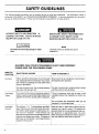
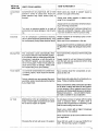
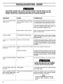
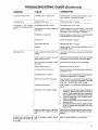
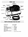
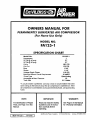
OWNERS
MANUAL
FOR
PERMANENTLY LUBRICATED AIR COMPRESSOR
(For Home Use Only)
MODEL NO.
FA125-1
SPECIFICATION
Model
CHART
No.
FA125-1
Horsepower
SCFM @ 40 psig
1
3.7
SCFM @ 90 psig
Cut-In
Cut-Out
2.7
100 PSI
125 PSI
Bore
Stroke
1 3/4"
1 1/4"
Voltage-Single
Phase
Minimum Branch Circuit Requirement
*Fuse Type
Amperage
at Max. Pressure
Tank Size
110-120
15 AMPS
Quick Acting
10
2.5 Gallon
*A circuit breaker is preferred. Use only a fuse or circuit breaker that is the
same rating as the branch circuit the air compressor
is operated on, If the
air compressor
fuses.
is connected
NOTE:
to a circuit protected
IMPORTANT:
For identification of Repair
Parts, see Page 12 in this
Manual.
MGP-FA125-1
11/15/93
WARRANTY"
Read and retain the Safety
Guidelines and All InskucUons Carefully
Operating.
DeViJbiss
I
by fuses, use quick acting
I
See Page 3 of this Manual
for Warranty Information.
Before
Air Power
Company
. 213
#ndus_ial
Drive
- Jackson,
TN 38307-96?5
TABLE OF CONTENTS
Page
ON-RECEIPT
INSPECTION
WARRANTY
SAFETY
(SP-100-C)
GUIDELINES
WARNING
..................
Page
2
Location of Air Compressor
............
Extension Cords ................................
7
7
.......................
3
7
8
..........................
4
Voltage and Circuit Protection ..........
Grounding Instructions ......................
Additional Regulators and
Controls ............................................
Break-In Procedures .........................
CHART ..............................
4-5
...........................................
6
OPERATING
DUTY CYCLE ........................................
6
TROUBLESHOOTING
STORAGE
6
COMPRESSOR
GLOSSARY
.............................................
DESCRIPTION
OF OPERATION
.......... 7
INSTALLATION
PROCEDURES
AND BREAK-IN
...................................
PROCEDURES
8
8
................ 9
GUIDE ......... 10-11
PARTS LIST ..............
HOW TO ORDER REPAIR
PARTS ...................................
12
Back Cover
7-8
In the unlikely event you should have a problem with this product or if you
are missing any parts, it is not necessary to return it to the store where you
purchased it. Simply call our toll-free number and talk with our Service
Representative.
OUR
OFFICE HOURS ARE FROM
8:00 a.m. to 4:30 p.m. (CST)
MONDAY THROUGH
FRIDAY
CALL TOLL-FREE
2
1-800-888-2468,
Ext. 2
ONE
LIMITED
YEAR FROM
WARRANTY
DATE OF PURCHASE
At/merchandise
monuloctured
by De Vilbiss Air Power Company is warranted to be/tee o/dejects in workmanshlp
and material which occur during the/irst year/ram
the dote of purchose
by the original purchaser
(t?litiol user)
Products covered under this warranty inc/ude: air compressors,
°air toots, accessories
and service pods.
De Vilbtss Air Power wilt repair or replace, at De Vilbiss "soption, products or components
which have [oi/ed within the
warranty perio_
Repair or rep/ocement,
andservice
coils on 60 and 80 gallon ark compressors,
wlYlbe handled by
Authorized
Warranty Service Centers and will be scheduled
and serviced according
to the normo/ work [tow at the
service center/ocotion,
and depending
on the oval/ability o/replacement
ports
A]/ decisions
o/DeVilbiss
Air Power Company
with regard
to thts policy
shol/ be final
This warranty gives you specific legal rights, and you may o/so hove other rights which vary [ram stole to state.
RESPONSIBILITYOF ORIGINAL PURCHASER(Initial User):
]
O
O
Retainoriginal sales receiptsas proof of purchase for warrantywork.
Use reasonable care in the operation and maintenance of the product as described in the Owners Manual(s).
Deliverorshiptheproduct to the nearest DeVilbiss Air Power Authorized Warranty ServiceCenter. Freight
costs, if any, must be paid bythe purchaser.
o Air compressorswith 60 and 80 gallon tanks only will be inspected at the site of installation. Contact the
nearest Authorized Warranty ServiceCenter, that provides on-site servicecalls, for servicecall arrangement.
Q If the purchaser does not receive satisfactory resubsfrom theAuthonzed Warronty ServiceCenter, the
purcha_r should contad DeVilbissAir PowerCompany.
THIS WARRANTYDOES NOT COVER."
]
r3 Merchanise s_d _s_rec_nditi_ned__oor m_de_sand/or disp_aym_de_ss_d "as is'_any damaged _r
incomplete equipment sold "as is".
0 Merchandise used as"rental" equipment.
Merchandise that has become inoperative because of ordinarywear, misuse, negligence, accident, im
proper and/or unauthorized repair or alterations including failure to operate the product in accordance with
the instructionsprovided in the Owners Manual (s)supplied with the product.
o An air compressor that pumps air more than 50°/0during a one hour period is considered misuse because
the air compressor is undersizedfor the required air demand. Maximum compressor pumping time per hour is
30 minutes.
Q Merchandise sold by DeVilbissAir Powerwhich has been manufactured by and identified as the product of
another company. The product manufacturer's warrantywill apply.
Q Repairand h'ansportation costs of merchandise determined not to be defective.
Cost associatedwith assembly, required oil, adjustmentsor other installation and start-up cost.
Q ANY INCIDENTAL, INDIRECTOR CONSEQUENTIAL LOSS, DAMAGE, OR E)OENSETHATMAY RESULT
FROM ANY DEFECT,FAILUREOR MALFUNCTION OF THE PRODUCT. Some states do not allowthe
exclusionor limitation of incidental or consequential damages, so the above limitation or exclusionmay not
apply to you.
c_ IMPUEDWARRANTIES,INCLUDING THOSE OF MERCHANTABIUTYAND FITNESSFOR A PARTICULAR
PURPOSE,AREUMITED TO ONE YEARFROM THE DATEOF ORIGINAL PURCHASE.Some statesdo not
allow limitations on how long an implied warranty lasts,so the above limitations may not apply to you.
"AirTools: O-Rings and drier
period
Form:
6/4/93
o[45
_ys
MaNes are consiNered ordinary vceor paris, therefore,/hey
are warronled
/ram the date of purchose.
SP-IO0-C
213 Industti=l
Ori_
• Jackson, TN 38301.9615
• Telephone:
1_00-8_8-2468
. Exl 2 " FAX
1.800.888.9036
[or a
SAFETY GUIDELINES
"Fhis manual contains information that is important for you to know and understand. This information relates to
protecting YOUR SAFETY and PREVENTING EQUIPMENT PROBLEMS. To help you recognize this information,
we use the following symbols. Please read the manual and pay attention to these sections.
URGENT SAFETY INFORMATION
-A
HAZARD THAT WILL CAUSE SERIOUS
INJURY OR LOSS OF LIFE.
IMPORTANT
SAFETY INFORMATION
A HAZARD THAT MIGHTCAUSE
SERIOUS INJURY OR LOSS OF LIFE.
NOTE
Infon'nation for preventing damage to equipment.
Information that you should pay special
attention to.
HAZARDS CAN OCCUR IF EQUIPMENT
IS NOT USED PROPERLY.
PLEASE READ THE FOLLOWING
CHART.
WHAT TO
LOOK FOR
Hot Parts
Flammable
Vapors
WHAT COULD HAPPEN
HOW TO PREVENT IT
When operated continuously, the air hose gets
hot, especially near the compressor. If you maintain contact by grasping you may suffer minor
bums or discomfort.
Never touch the air compressor head during or
immediately after operation.
On tank mounted units, the plumbing between
the pump and tank gets hot.
On tank mounted units, avoid prolonged contact
with the pump to tank plumbing.
It is normal for the motor and pressure switch to
spark. A spark can ignite flammable vapors from
gasoline or solvents, causing a fire or explosion.
The air compressor must only be used in well
ventilated areas, free of gasoline or solvent vapors.
Do not operate the compressor while you are
carrying it, or in the spray area.
Unsuitable
Solvents
The solvents 1,1,1 - Trichloroethane and Methylene Chloride can chemically react with aluminum used n paint spray guns, pant pumps, etc.,
I and cause an explosion. These solvents can
also react with galva nized components and cause
corrosion and weaken ng of parts. Thisdoes not
Jaffect your air compressor - but it may affect the
i equipment being used.
Read the label or data sheet supplied with the
material you intend to spray. If it contains the
solvents listed do not use accessories that contain aluminum or galvanized parts. You must
either change the material you intend to spray, or
use only stainless steel spray equipment.
WHAT TO
LOOK FOR
--
Compressed
Air
WHAT COULD HAPPEN
!
[ Compressed air can propel dust, did or loose
padicles it comes in contact with. These propelled particles may cause serious injury or
damage.
HOW TO PREVENT IT
Never point any nozzle or sprayer toward a
3erson or any part of the body.
Always wear safety goggles
using the air compressor•
or glasses when
Always turn the air compressor off before attaching or removing accessories•
Too much air pressure applied to air tools or
accessories can cause damage or risk of bursting.
Electricity
Check the manufacturer's pressure rating for air
tools and accessories. Regulator outlet pressure
must never exceed the maximum pressure rating
Always unplug the air compressor prior to mainYour air compressor is powered by electdcity.
Like any other electrically powered device, if it is tenance or repair.
not used properly it may cause electrical shock. Never use the air compressor in the rain.
Always plug the cord into an electrical outlet with
the specified voltage and adequate fuse protection.
Moving Pads
Toxic Vapors
This compressor cycles automatically when
the pressure switch is in the ON/OFF position.
If you attempt repair or maintenance while the
compressor is operating, or with the switch in
the ON/AUTO position, you can expose yourself to moving parts. These moving parts can
cause serious injury or damage if they come
into contact with you or your clothing.
It is normal for compressed air to contain toxic
or irritating vapors. Such vapors are harmful
if inhaled.
Certain materials you are spraying (like paint,
weed killer, sand or insecticide) can be harmful
if you inhale them.
Never operate the compressor with the belt guard
removed.
Always unplug the unit and release air pressure
from the tank and any accessories before doing
repair or maintenance.
:Never directly inhale the compressed
duced by this unit.
air pro-
Read labels and safety data for all materials you
spray. Follow all safety precautions.
Read and follow the safety instructions provided
on the label or safety data sheet for the material
you are spraying. Use a respirator mask if there
is a chance of inhaling anything you are spraying.
Read all instructions..,
be sure that the respirator mask is suitable for your application.
Air Tank
Modifications to the air compressor in an attempt to reach higher air pressure can cause
the air tank to rupture or explode.
Do not adjust, remove or tamper with the safety
valve or pressure switch. If safety valve or
pressure switch replacement is necessary, a part
with the same rating must be used.
Never use a motor with a higher horsepower
rating than the one supplied.
Never replace the air tank with a different model
or a larger tank.
Changing the air tank will cause it to weaken.
Never drill into, weld or in any way modify the air
I tank. The tank may rupture or explode.
5
GLOSSARY
SCFM or CFM: Standard Cubic Feet per Minute; a unit
of measurement of air delivery.
PSIG or PSI: Pounds per square inch gauge.
CUT-IN PRESSURE: While the motor is off, air tank
pressure drops as you continue to use your accessory.
When the tank pressure drops to a certain tow level the
motor will restart automatically. The low pressure at
which the motor automatically re-starts is called "cut-in
pressure."
CUT-OUT PRESSURE: When you turn on your air
compressor and it begins to run, air pressure in the air
tank begins to build. It builds to a certain high pressure
before the motor automatically shuts off .The high pressure at which the motor shuts off is called "cut-out
pressure."
DUTY CYCLE
All DeVilbiss Air Power manufactured air compressors should be operated on not more than a 50% duty cycle. This
means an air compressor that pumps air more than 50% of one hour is considered misuse, because the air compressor
is undersized for the required air demand. Maximum compressor pumping time per hour is 30 minutes.
STORAGE
you have _
1. Set the "ON/OFF"
cord.
2.
switch to "OFF" and unplug the
Relieve all pressure from the air compressor head
and air hose by setting the opening the regulator.
using lt_ air compre_.
3. Protect the electrical cord and air hose from damage
by winding them loosely around the air compressor.
4.
Store the air compressor in a clean and dry location.
DESCRIPTION
OF OPERATION
Air Compressor Pump: To compress air, the piston
moves up and down in the cylinder. On the downstroke,
air is drawn in through the air intake valves. The exhaust
valves remain closed. On the upstroke of the piston, air
is compressed. The intake valves close and compressed
air is forced out through the exhaust valves, through the
outlet tubes, through the check valve and into the air tank.
Working air is not available until the compressor has
raised the air tank pressure above that required at the air
outlet.
Check Valve: When the air compressor is operating, the
check valve is "open", allowing compressed air to enter
the air tank. When the air compressor reaches "cut-out"
pressure, the check valve "closes", allowing air pressure
to remain inside the air tank.
decrease pressure. To avoid minor readjustment after
making a change in pressure setting, always approach
the desired pressure from a lower pressure.
When
reducing from a higher to a lower setting, first reduce to
some pressure less than that desired, then bring up to the
desired pressure. Depending on the air requirements of
each particular accessory, the outlet regulated air pressure may have to be adjusted while operating the accessory.
OutJet Pressure Gauge:
The outlet pressure gauge
indicatesthe air pressure available at the outlet side of the
regulator. This pressure is controlled bythe regulator and
is always less or equal to the tank pressure.
See
"Operating Procedures".
This unit DOES NOT require
Tank Pressure Gauge:
The tank pressure gauge
indicates the reserve air pressure in the tank.
Pressure Switch: The pressure switch automatically
starts the motor when the air tank pressure drops below
the factory set "cut-in" pressure. It stops the motor when
the air tank pressure reaches the factory set "cut-out"
pressure.
Cooling System:
This compressor contains an advanced design cooling system. At the heart of this cooling
system is an engineered fan. It is perfectly normal for this
fan to blow air through the vent holes in large amounts.
You know that the cooling system is working when air is
being expelled.
Pressure Release Valve:
a pressure release valve.
Motor Thermal
Overload
Protector:
The electdc
motor has an automatic thermal ovedoad protector. If the
motor overheats for any reason, the thermal overload
protector will shut off the motor. The motor must be
allowed to cool before restarting.
Regulator: The air pressure coming from the air tank is
controlled by the regulator.
Turn the regulator knob
clockwise to increase pressure and counter-clockwise to
INSTALLATION
AND
Circuit
Protection
The advance design of this unit
Drain Valve: The drain valve is located at the base of
the air tank and is used to drain condensation at the end
of each use.
On/Auto-Off
Switch: Turn this switch ON to provide
automatic power to the pressure switch and OFF to
remove power at the end of each use.
BREAK-IN
Location
of the Air Compressor
Your compressor comes to you completely assembled
and ready for use. Operate the air compressor in a dry,
clean, cool and well ventilated area. The air compressor
pump and case are designed to allow for proper cooling.
Clean or blow off dust or dirt that collects on the air
compressor.
A clean air compressor runs cooler and
provides longer service. The ventilation openings on
your air compressor are necessary to maintain proper
operating temperature.
Do not place rags or other
containers on or near these openings.
Voltage
and
See front cover.
Air Intake Filter:
requires no air filter.
PROCEDURES
Extension
Cords
Use extra air hose instead of an extension cord to
avoid voltage drop and power loss to the motor.
If an extension cord must be used, be sure it is:
a 3-wire extension cord that has a 3-blade grounding plug, and a 3-slot receptacle that will accept
the plug on the compressor
in good condition
no longer than 50 feet
14 gauge (AWG) or larger. (VVire size increases
asgauge number decreases.) 12 AWG, IOAWG
and 8 AWG may also be used. DO NOT USE 16
OR 18 AWG.
7
TROUBLESHOOTING
GUIDE
PERFORMING
REPAIRS MAY EXPOSE VOLTAGE SOURCES, MOVING
PARTS OR COMPRESSED AIR SOURCES. PERSONAL INJURY MAY OCCUR. PRIOR TO A'n'EMPTING ANY
REPAIRS, UNPLUG THE COMPRESSOR AND BLEED OFF TANK AIR PRESSURE.
PROBLEM
CAUSE
i CORRECTION
Excessive tank pressure- safety
valve pops off
Pressure switch does not shut off motor
when compressor reaches "cut-out"
pressure
Move the pressure switch lever to the "OFF" position
It the outfit doesn't shut off, and the electrical conta cts
are welded together, replace the pressure switch.
If the contacts are good, check to see if the pin in the
bottom of the pressure release valve is stuck If it
does not move freely, replace the valve
Air leaks at fittings.
Air leaks at or inside
check
Pressure switch "cut-out* too high,
Return the outfit to an authorized dealer to check and
adjust, or replace switch,
Tube fittings are not tight enough.
Tighten fittings where air can be heard escaping
Check fittings with soapy water solution DO NOT
OVER-TIGHTEN.
Defective or dirty check valve.
A defective check valve results in a constant air leak
at the pressure release valve where there is pressure
in the tank and the compressor is shut off. Remove
and clean or replace check valve. DO NOT OVERTIGHTEN.
Defective pressure switch release
valve.
Remove and replace the release valve.
Defective check valve.
A defective check valve results in a constant air leak
at the pressure release valve when there is pressure
in the tank and the compressor is shut off. Remove
and clean or replace check valve. DO NOT OVERTIGHTEN.
Defective air tank.
Air tank must be replaced.
valve.
Air leaks at pressure
release valve.
switch
Air leaks in air tank or at air tank
welds.
Do not repair the leak.
DO NOT DRILL INTO, WELD OR OTHERWISE
MODIFY AIR TANK OR IT WILL WEAKEN.
THE TANK CAN RUPTURE OR EXPLODE.
Air leaks between
valve plate,
head and
Pressure reading on the regulated pressure gauge drops
when an accessory is used.
Leaking gasket.
Itis normalfor'some"pressure
occur.
Torque head screwsto
leak, replace gasket.
dropto
8 ft. lbs. lfthis does not stop
If there is an excessive amount of pressure drop
when the accessory is used. adjust the regulator
following the instructions on page 10.
NOTE
Adjust the regulated pressure underflow
conditions (while accessory is being
used).
10
TROUBLESHOOTING
GUIDE
(Continued)
PROBLEM
CAUSE
CORRECTION
Air leak from safety valve
Possible defect in safety valve
Operate safety valve manually by pulling on ring
valve still leaks, it should be replaced.
If
Knocking Noise
Defective check valve.
Remove and clean, or replace.
Compressor
is not supplying
enough air to operate accessories.
Prolonged excessive use of air.
Decrease amount of air usage
Compressor is not large enough for air
requirement,
Check the accessory air requirement.
If it is higher
than the SCFM or pressure supplied by your air
compressor, you need a larger compressor.
Restricted air intake filter.
Clean or replace air intake filter. Do not operate the
air compressor in the paint spray area.
Hole in hose.
Check and replace if required.
Check valve restricted.
Remove and clean, or replace.
Air leaks.
Tighten fittings.
(See Air Leaks Section
bleshooting Guide.)
Motor overload protection switch has
tripped,
Let motor cool off and overload switch will automatically reset.
Tank pressure
exceeds
switch "cut-in" pressure.
Motor will start automatically when tank pressure
drops below "cut-in" pressure of pressure switch.
Motor will not run
pressure
Wrong gauge wire or length of extension cord.
Check for proper gauge wire and cord length.
Check valve stuck open
Remove
Loose electrical connections
Check wiring connection inside pressure switch and
terminal box area.
Possible defective capacitor.
Return to an Authorized Warranty Service Center for
inspection or replacement, if necessary.
Paint spray on internal motor parts
Have checked at an Authorized Warranty Service
Center. Do not operate the compressor in the paint
spray area. See flammable vapor warning.
Possible defective motor.
Have checked
Center.
Fuse blown, circuit breaker tripped.
1.
2.
3.
4.
Pressure
release valve
switch has not unloaded
on pressure
head pres-
sure.
Regulator knob continuous air
leak Regulator will not shut off
at air outlet
of Trou-
Dirty or damaged
)arts.
regulator
internal
and clean, or replace.
at an Authorized Warranty Service
Check fuse box for blown fuse and replace, if
necessary. Reset circuit breaker. Do not use a
fuse or circuit breaker with higher rating than
that specified for your particular branch circuit,
Check for proper fuse; only "Fusetron" type T
fuses are acceptable.
Check for low voltage conditions and/or proper
extension cord.
Disconnect the other electrical appliances from
circuit or operate the compressor in its own
branch circuit.
Bleed the line by pushing the lever on the pressure
switch to the "off" position; if the valve does not open,
replace it.
Clean or replace regulator,
or internal parts
11
PARTS LIST
OUTLET
PRESSURE GAUGE
PRESSURE
SWITCH
SAFETY VALVE
TANK
PRESSURE
GAUGE
COMPRESSOR
ASSEMBLY
j
_
CHECK VALVE
_(Not
REGULATOR
Shown)
AIR TANK
AIR HOSE
(Not Shown)
DRAIN VALVE
_/_
AIR CHUCK
PARTS AVAILABLE FOR THIS UNIT
DESCRIPTION
2
PART NUMBER
AIR CHUCK ............................................
REGULATOR
.........................................
TANK PRESSURE GAUGE ....................
OUTLET PRESSURE GUAGE ...............
SAFETY VALVE .....................................
DRAIN VALVE ........................................
CHECK VALVE .......................................
REPLACEMENT
PRESSURE
SSH-8
CAC-4296-1
C-GA-345
C-GA-345
TIA-4150
SS-2707
CAC-1275
SWITCH
DAC-4105
.................................................
(100 to 125 PSI)
SERVICE NOTES
PERMANENTLY
LUBRICATED
AIR C()MPRESSOR
MODEL NO.
Attach Sales Receipt
here.
Retain Original Sales
Receipt as Proof of
Purchase for Warranty
Repair Work.
FA125-1
An "Authorized
your unit.
Warranty
Service Center Directory"
is included
When ordering repair parts from your local Authorized
Center, always give the following information:
number
with
Service
•
Model
of your compressor
•
Port number and description of the item
you wish to purchase.
If you have any questions or need the Ioadion of the nearest
Authorized
Service Center call our Cuslomer Service Holline
(Toll-Free) 1-800-888-2468,
Ext. 2, Monday thru Friday 8 a.m.
to 4:30 p.m. (CST) and talk with our Trained Customer Service
Representatives.
Themodel numbercanbe found
onIhe maintenancelabel onthe
air tank.
The codenumberwhichcanbe
Ioundonthe loll label onthe rear
of the air tank.
The ManufacturesNumber
(ASMEcodecompressoronly)
is locatedonthemetaldata
platewhichis weldedonto the
backsideofthe air tank
Model
No.
Code
MFG
No.
No.
DeVilbiss Ai_ Power Company
. 213 Industrial Drive
• Jackson, TN 38301-9615