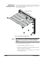
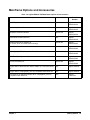
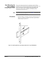
1
75000 Series C Agilent E8401A and E8403A C-Size VXI Mainframes User and Service Manual Where to Find it - Online and Printed Information This manual is distributed as follows: Agilent Universal Instrument Drivers CD ROM ( included with the mainframe) World Wide Web at http://www.agilent.com/find/products For related information: System installation (hardware/software) ............VXIbus Configuration Guide* * Supplied with Agilent Command Module, Embedded Controllers, and VXLink *E8401-90001* Manual Part Number: E8401-90001 Printed in Malaysia E0912 Contents Agilent E8401A, E8403A User and Service Manual Edition 2 AGILENT TECHNOLOGIES WARRANTY STATEMENT..................................... 3 U.S. Government Restricted Rights.............................................................................. 3 Safety Symbols ............................................................................................................. 4 WARNINGS................................................................................................................. 4 Chapter 1 Getting Started ............................................................................................................... 7 Product Overview ......................................................................................................... 7 Preparing Your VXI System for Use............................................................................ 8 AC Power Requirements ....................................................................................... 8 Positioning the Mainframe for Adequate Cooling ................................................ 8 Connecting the Mainframe to a Permanent Earth Ground ............................................................. 9 Installing VXI Instruments ......................................................................................... 10 Installing C-Size Instruments .............................................................................. 11 Installing A- and B-Size Instruments .................................................................. 12 Front Panel Features ................................................................................................... 13 Diagnostic Connector ................................................................................................. 14 +5VC (pin 6) .................................................................................................................. 15 +12VC (pin 7) .................................................................................................................. 15 +5V STDBY (pins 8, 21) .......................................................................................................... 15 SYSRESET* (pin 10) ................................................................................................................ 15 ACFAIL* (pin 23) ................................................................................................................ 15 Using the Remote Power-On Pins ....................................................................... 16 Disabling the On/Stdby Switch ........................................................................... 17 Mainframe Options and Accessories .......................................................................... 19 Chapter 2 Rack Mounting and Option Installation ................................................................... 21 Chapter Overview ....................................................................................................... 21 Rack Mounting the Agilent E840xA Mainframe ....................................................... 21 Parts List .............................................................................................................. 22 Rack Mounting the Agilent E840xA using Support Rails .................................. 23 Procedure ............................................................................................................. 23 Rack Mounting the Agilent E840xA Using Rack Slide Rails ............................ 27 Procedure ............................................................................................................. 27 Installing the Cable Tray............................................................................................. 33 Parts List .............................................................................................................. 33 Procedure ............................................................................................................. 33 Contents 1 Installing the Tinted Acrylic Door (Option 915) ........................................................ 35 Parts List .............................................................................................................. 35 Installing the Intermodule Chassis Shields ................................................................. 37 Parts List .............................................................................................................. 37 Procedure ............................................................................................................. 37 Installing the Backplane Connector Shields ............................................................... 39 Parts List .............................................................................................................. 39 Procedure ............................................................................................................. 39 Agilent E840xA Air Filter Kit .................................................................................... 41 Chapter 3 Servicing Your Mainframe ......................................................................................... 43 Chapter Overview ....................................................................................................... 43 Problem Isolation........................................................................................................ 43 No Power Line Fuse ............................................................................................ 43 Isolating Problems ............................................................................................... 44 Replacing Assemblies................................................................................................. 44 Removing the Rear Panel from the Mainframe .................................................. 45 Removing the Mainframe Cover ......................................................................... 46 Replacing the Basic Monitor Board .................................................................... 47 Replacing the Agilent E8401A Power Supply .................................................... 48 Replacing the Agilent E8403A Power Supply .................................................... 49 Replacing the Impeller ........................................................................................ 50 Replacement Power Cords.......................................................................................... 51 Appendix A Agilent E8401A, E8403A Product Specifications ..................................................... 53 Product Descriptions................................................................................................... 53 General Specifications ......................................................................................... 53 Mechanical Specifications ................................................................................... 53 Output Power Specifications ...................................................................................... 54 Total Available and Usable Power ...................................................................... 54 Peak and Dynamic Current ................................................................................. 54 Output Voltage Specifications ............................................................................ 55 Input Power Requirements.......................................................................................... 55 Cooling Specifications................................................................................................ 56 Cooling Specification Charts .............................................................................. 56 Acoustical Noise Specifications ................................................................................. 58 Backplane Specifications ............................................................................................ 58 Basic Monitor Specifications...................................................................................... 58 Environmental Specifications ..................................................................................... 59 2 Contents AGILENT TECHNOLOGIES WARRANTY STATEMENT AGILENT PRODUCT: Agilent E8401A, E8403A C Size VXI Mainframes DURATION OF WARRANTY: 3 years 1. Agilent Technologies warrants Agilent hardware, accessories and supplies against defects in materials and workmanship for the period specified above. If Agilent receives notice of such defects during the warranty period, Agilent will, at its option, either repair or replace products which prove to be defective. Replacement products may be either new or like-new. 2. Agilent warrants that Agilent software will not fail to execute its programming instructions, for the period specified above, due to defects in material and workmanship when properly installed and used. If Agilent receives notice of such defects during the warranty period, Agilent will replace software media which does not execute its programming instructions due to such defects. 3. Agilent does not warrant that the operation of Agilent products will be uninterrupted or error free. If Agilent is unable, within a reasonable time, to repair or replace any product to a condition as warranted, customer will be entitled to a refund of the purchase price upon prompt return of the product. 4. Agilent products may contain remanufactured parts equivalent to new in performance or may have been subject to incidental use. 5. The warranty period begins on the date of delivery or on the date of installation if installed by Agilent. If customer schedules or delays Agilent installation more than 30 days after delivery, warranty begins on the 31st day from delivery. 6. Warranty does not apply to defects resulting from (a) improper or inadequate maintenance or calibration, (b) software, interfacing, parts or supplies not supplied by Agilent, (c) unauthorized modification or misuse, (d) operation outside of the published environmental specifications for the product, or (e) improper site preparation or maintenance. 7. TO THE EXTENT ALLOWED BY LOCAL LAW, THE ABOVE WARRANTIES ARE EXCLUSIVE AND NO OTHER WARRANTY OR CONDITION, WHETHER WRITTEN OR ORAL, IS EXPRESSED OR IMPLIED AND AGILENT SPECIFICALLY DISCLAIMS ANY IMPLIED WARRANTY OR CONDITIONS OF MERCHANTABILITY, SATISFACTORY QUALITY, AND FITNESS FOR A PARTICULAR PURPOSE. 8. Agilent will be liable for damage to tangible property per incident up to the greater of $300,000 or the actual amount paid for the product that is the subject of the claim, and for damages for bodily injury or death, to the extent that all such damages are determined by a court of competent jurisdiction to have been directly caused by a defective Agilent product. 9. TO THE EXTENT ALLOWED BY LOCAL LAW, THE REMEDIES IN THIS WARRANTY STATEMENT ARE CUSTOMER’S SOLE AND EXLUSIVE REMEDIES. EXCEPT AS INDICATED ABOVE, IN NO EVENT WILL AGILENT OR ITS SUPPLIERS BE LIABLE FOR LOSS OF DATA OR FOR DIRECT, SPECIAL, INCIDENTAL, CONSEQUENTIAL (INCLUDING LOST PROFIT OR DATA), OR OTHER DAMAGE, WHETHER BASED IN CONTRACT, TORT, OR OTHERWISE. FOR CONSUMER TRANSACTIONS IN AUSTRALIA AND NEW ZEALAND: THE WARRANTY TERMS CONTAINED IN THIS STATEMENT, EXCEPT TO THE EXTENT LAWFULLY PERMITTED, DO NOT EXCLUDE, RESTRICT OR MODIFY AND ARE IN ADDITION TO THE MANDATORY STATUTORY RIGHTS APPLICABLE TO THE SALE OF THIS PRODUCT TO YOU. U.S. Government Restricted Rights The Software and Documentation have been developed entirely at private expense. They are delivered and licensed as "commercial computer software" as defined in DFARS 252.227- 7013 (Oct 1988), DFARS 252.211-7015 (May 1991) or DFARS 252.227-7014 (Jun 1995), as a "commercial item" as defined in FAR 2.101(a), or as "Restricted computer software" as defined in FAR 52.227-19 (Jun 1987)(or any equivalent agency regulation or contract clause), whichever is applicable. You have only those rights provided for such Software and Documentation by the applicable FAR or DFARS clause or the Agilent standard software agreement for the product involved. E8401A, E8403A C-Size VXI Mainframes User/Service Manual Edition 2 Copyright © 1997, 1998, 2001 Agilent Technologies, Inc. All rights reserved. 3 Documentation History All Editions and Updates of this manual and their creation date are listed below. The first Edition of the manual is Edition 1. The Edition number increments by 1 whenever the manual is revised. Updates, which are issued between Editions, contain replacement pages to correct or add additional information to the current Edition of the manual. Whenever a new Edition is created, it will contain all of the Update information for the previous Edition. Each new Edition or Update also includes a revised copy of this documentation history page. Edition 1 . . . . . . . . . . . . . . . . . . . . . . . . . . . . . . . . . . . . . . . . . . . . . . . .May 1998 Edition 2 . . . . . . . . . . . . . . . . . . . . . . . . . . . . . . . . . . . . . . . . . . .September 2001 Edition 2 Rev 1 . . . . . . . . . . . . . . . . . . . . . . . . . . . . . . . . . . . . . .September 2012 Safety Symbols Instruction manual symbol affixed to product. Indicates that the user must refer to the manual for specific WARNING or CAUTION information to avoid personal injury or damage to the product. Alternating current (AC) Direct current (DC). Indicates hazardous voltages. Indicates the field wiring terminal that must be connected to earth ground before operating the equipment — protects against electrical shock in case of fault. or Frame or chassis ground terminal—typically connects to the equipment's metal frame. Calls attention to a procedure, practice, or WARNING condition that could cause bodily injury or death. Calls attention to a procedure, practice, or CAUTION condition that could possibly cause damage to equipment or permanent loss of data. WARNINGS The following general safety precautions must be observed during all phases of operation, service, and repair of this product. Failure to comply with these precautions or with specific warnings elsewhere in this manual violates safety standards of design, manufacture, and intended use of the product. Hewlett-Packard Company assumes no liability for the customer's failure to comply with these requirements. Ground the equipment: For Safety Class 1 equipment (equipment having a protective earth terminal), an uninterruptible safety earth ground must be provided from the mains power source to the product input wiring terminals or supplied power cable. DO NOT operate the product in an explosive atmosphere or in the presence of flammable gases or fumes. For continued protection against fire, replace the line fuse(s) only with fuse(s) of the same voltage and current rating and type. DO NOT use repaired fuses or short-circuited fuse holders. Keep away from live circuits: Operating personnel must not remove equipment covers or shields. Procedures involving the removal of covers or shields are for use by service-trained personnel only. Under certain conditions, dangerous voltages may exist even with the equipment switched off. To avoid dangerous electrical shock, DO NOT perform procedures involving cover or shield removal unless you are qualified to do so. DO NOT operate damaged equipment: Whenever it is possible that the safety protection features built into this product have been impaired, either through physical damage, excessive moisture, or any other reason, REMOVE POWER and do not use the product until safe operation can be verified by service-trained personnel. If necessary, return the product to a Hewlett-Packard Sales and Service Office for service and repair to ensure that safety features are maintained. DO NOT service or adjust alone: Do not attempt internal service or adjustment unless another person, capable of rendering first aid and resuscitation, is present. DO NOT substitute parts or modify equipment: Because of the danger of introducing additional hazards, do not install substitute parts or perform any unauthorized modification to the product. Return the product to a Hewlett-Packard Sales and Service Office for service and repair to ensure that safety features are maintained. 4 Declaration of Conformity Declarations of Conformity for this product and for other Agilent products may be downloaded from the Internet. There are two methods to obtain the Declaration of Conformity: • Go to http://regulations.corporate.agilent.com/DoC/search.htm. You can then search by product number to find the latest Declaration of Conformity. • Alternately, you can go to the product web page (www.agilent.com/find/E8401A), click on the Document Library tab then scroll down until you find the Declaration of Conformity link. 5 Notes: 6 Chapter 1 Getting Started This chapter contains general information on the operating features of the Agilent E8401A and E8403A C-Size VXI mainframes. The following table lists the differences between these two mainframes: Power Supply (0 °C to 55 °C) 500 W 1000 W Agilent E8401A Mainframe Agilent E8403A Mainframe Basic Monitor Unless otherwise specifically noted, descriptions in this manual relate to both VXI mainframes. The designation Agilent E840xA refers to both VXI mainframes. Product Overview The Agilent E840xA VXI mainframes are designed in full compliance with VXIbus specification revision 1.4, VXIplug&play specification VPP-8, and VMEbus system specification revision C.1. Additional features of the Agilent E840xA mainframes include: • Mainframe monitoring for verification of: backplane voltage conditions mainframe temperatures fan and impeller operation • State of the art cooling technology: quiet, variable speed power supply fan and backplane impeller increased static pressure all fans operate at either full speed or in variable speed mode. • Front Panel Diagnostic Connector for: power supply voltage measurements power supply and backplane temperature measurements power supply fan and backplane impeller verification • Easy maintenance: easy rear panel access to power supply and cooling impeller (either bench or rack mount operation). optional air filter kit is available for harsh environments. Chapter 1 Getting Started 7 Preparing Your VXI System for Use The Agilent E840xA mainframes are shipped from the factory ready to use. This section describes important mainframe installation procedures. AC Power Requirements The Agilent E840xA mainframes can be operated at line voltages of 90 VAC to 264 VAC, and line frequencies of 47 Hz to 66 Hz. The mainframe can also operate at 360 Hz to 440 Hz with line voltages of 90 VAC to 132 VAC. The mainframes ship with a power cord and with a fuse installed in the power supply. The fuse is suitable for all line voltages, but is not accessible. Appendix A contains complete input power specifications. WARNING The power cord is the only way to disconnect the mainframe from AC power and, therefore, it must be accessible to the operator at all times. When the Agilent E840xA mainframes are mounted in a system cabinet, the power cord need not be accessible since the cabinet must have its own disconnect device. Positioning the Mainframe for Adequate Cooling VXI instruments are cooled by air drawn through the back of the mainframe and exhausted out the sides. The power supply is cooled by air drawn from the right side (facing the mainframe) and exhausted out the left side. When placing the mainframe on a work bench or if the mainframe is rack mounted, provide at least a one inch clearance at the back and sides to allow for proper air flow. Air filters are not necessary on these mainframes. However, an optional air filter kit (mainframe option 938 or Agilent E8401-80938) is available for use in harsh environments. The airflow is restricted less than 10% with the air filter installed. Refer to “Agilent E840xA Air Filter Kit” on page 41 for installation information. 8 Getting Started Chapter 1 Connecting the Mainframe to a Permanent Earth Ground The mainframe must be connected to a permanent earth ground for line frequencies greater than 66 Hz. This connection is made on the back of the mainframe: 1. Connect a 16 AWG (1.3 mm or larger) wire to the PEM nut shown in Figure 1-1. The wire must be green with a yellow stripe, or bare (no insulation). Use a m4 x 10 screw, grounding lug, and toothed washers (or toothed lug) as shown in the Figure. 2. Attach the other end of the wire to a permanent earth ground using toothed washers or a toothed lug. Figure 1-1. Connecting an Agilent E840xA Mainframe to a Permanent Earth Ground (Agilent E8403 shown, Agilent E8401 is similar) WARNING AVERTISSEMENT Chapter 1 For protection from electrical shock when operating at frequencies greater than 66 Hz, connect the chassis ground terminal to permanent earth ground. Risque de Choch èlectrique. Si la frèquence du secteur est supèrieure à 66 Hz, relier la borne de masse du chassis à une prise de terre fixe. Getting Started 9 Installing VXI Instruments The Agilent E840xA mainframes have 13 slots labeled 0 through 12. Any VXI instrument can be installed in any slot; however, slot 0 is reserved for devices capable of providing the system’s slot 0 functionality. This functionality includes: • locating instruments installed in the mainframe • managing (arbitrating) data flow across the backplane • providing the system clock (SYSCLK - 16 MHz) Examples of these devices are the Agilent E1406 Command Module and embedded controllers such as the Agilent E623x series VXI Pentium PCs, the Agilent RADEPC7B PC, and the Agilent E1497/E1498 V743 controllers. Multiple instruments which combine to create a virtual instrument (e.g. a scanning multimeter), and instruments which access the backplane local bus should be installed in adjacent slots. 1. To prevent damage to the VXI instruments, install the instruments when power is not applied to the mainframe. 2. Insert the instrument into the mainframe by aligning the instrument with the card guides inside the mainframe. Slowly push the instrument into the slot until it seats in the backplane connectors. The front panel of the instrument should be even with the front edges of the mainframe. 3. Tighten the retaining screws on the top and bottom of the module. WARNING 10 Getting Started All instruments within the VXI mainframe are grounded through the mainframe chassis. During installation, tighten the instrument's retaining screws to secure the instrument to the mainframe and to make the ground connection. Chapter 1 Installing C-Size Instruments Figure 1-2 shows the installation of C-Size instruments. seat the module by pushing in the extraction levers retaining screws extraction levers slide the module into the mainframe until it plugs into the backplane connectors Figure 1-2. Installing C-Size Instruments in the Agilent E840xA Mainframe WARNING Chapter 1 All instruments within the VXI mainframe are grounded through the mainframe chassis. During installation, tighten the instrument's retaining screws to secure the instrument to the mainframe and to make the ground connection. Getting Started 11 Installing A- and B-Size Instruments Figure 1-3 shows the installation of A- and B-size instruments. • Agilent E1403B A/B-size Module Carrier extends the P1 connector on the VXIbus backplane and mounts the (A/B-size) modules flush with C-size modules. This carrier is recommended for Agilent B-size, slave-only devices which have the P1 connector. • Agilent E1407A A/B Module Carrier extends the P1and P2 connectors on the VXIbus backplane. This carrier is recommended for B-Size, slave-only devices which have the P1/P2 connectors. Figure 1-3. Installing A- and B-Size Instruments in the Agilent E840xA Mainframe WARNING 12 Getting Started All instruments within the VXI mainframe are grounded through the mainframe chassis. During installation, tighten the instrument's retaining screws to secure the instrument to the mainframe and to make the ground connection. Chapter 1 Front Panel Features Section Power Indicator / Switch Description On Indicator Green - the mainframe is turned on. Standby Indicator Amber - the mainframe is in standby mode; no power is applied to the VXI modules. Voltages Indicator Green - all voltages on the VXI backplane are within ±8% of the VXI specification. Supply Flashing Amber - one or more voltages is out of specification. The backplane voltages and allowed variations are listed below: Voltage +5V +12V -12V +24V -24V -5.2V -2V Temp Indicator Allowed Variation +4.875V to +5.125V +11.64V to +12.6V -12.6V to -11.64V +23.28V to +25.2V -25.2V to -23.28V -5.46V to -5.044V -2.1V to -1.9V Diagnostic Pin 1 14 2 15 3 16 4 Green - the power supply temperature is acceptable. Flashing Amber - the power supply is approaching thermal shutdown. The power supply temperature can be measured on pin 11 of the Diagnostic connector. Fan Switch Fans Full - the power supply and mainframe cooling fans are operating at full speed. Var(iable) - the power supply and mainframe cooling fans are providing adequate cooling (default setting). Fan speed is a function of the power supply temperature and the reference temperature (Diagnostic connector pin 12). The reference temperature is a function of ambient temperature and load. Fans Indicator Green - the power supply and mainframe cooling fans are operating. Flashing Amber - the power supply fan or the mainframe cooling fan is not operating. Fan operation can be checked using pin 13 of the Diagnostic connector. Activity Indicator Green - there is communication between instruments across the backplane. Off - there is no communication between instruments on the backplane. SYSFAIL Indicator Flashing Amber - one or more instruments has asserted its SYSFAIL line due to a power-on initialization failure, self-test failure, or hardware failure. SYSFAIL is asserted momentarily at power on and during a system reset. Reset Switch Pressing the reset button asserts the SYSRESET* line on the VXI backplane. When asserted (low), this line resets the VXI system; all VXI instruments are rest to their power-on state. Backplane Refer to “Diagnostic Connector” on page 14. Diagnostic Connector Figure 1-4. Agilent E8401A and E8403A Basic Monitoring Front Panel Chapter 1 Getting Started 13 Diagnostic Connector The 25-pin Sub-D diagnostic connector provides access to backplane voltages, power supply and backplane temperatures, and output signals. The pins are described in Table 1-1. Table 1-1. Diagnostic Connector Pin Descriptions Pin # 14 Function Description 1 +5 VM +5V backplane voltage monitor (high impedance). (+4.875 Vdc to +5.125 Vdc) 2 -12 VM -12V backplane voltage monitor (high impedance). (-12.6 Vdc to -11.64 Vdc) 3 -24 VM -24V backplane voltage monitor (high impedance). (-25.2 Vdc to -23.28 Vdc) 4 -2 VM -2V backplane voltage monitor (high impedance). (-2.1 Vdc to -1.9 Vdc) 5 Rem On 6 +5 VC +5 VDC source output (1A maximum). 7 +12 VC +12 VDC source output (1A maximum). 8 +5 V Stdby Remote power on. See “Using the Remote Power-on Pins.” Input for +5V STDBY (1A maximum for pins 8 and 21 combined). 9 GND 10 SysReset * 11 PS Temp Output voltage proportional to power supply temperature (0 VDC at 0 °C, with a rise of 10 mV per degree centigrade). 12 Ref Temp Output voltage proportional to backplane temperature (0 VDC at 0 °C, with a rise of 10 mV per degree centigrade). A function of the ambient temperature and load. At no load, Tref ~ 2 °C + ambient. At full load and high fan speed, Tref ~ 14 °C + ambient. At full load and low fan speed, Tref ~ 20 °C + ambient. 13 Fans OK * TTL low-true output voltage indicates power supply and backplane cooling fans are operating. 14 +12 VM +12V backplane voltage monitor (high impedance). (+11.64 Vdc to +12.6 Vdc) 15 +24 VM +24V backplane voltage monitor (high impedance). (+23.28 Vdc to +25.2 Vdc) 16 -5.2 VM -5.2V backplane voltage monitor (high impedance). (-5.46 Vdc to -5.044 Vdc) 17 GND 18 REM Rtn 19 V OK * 20 GND 21 +5 V Stdby 22 GND 23 ACFAIL * 24 GND Chassis ground. 25 RSV Reserved. Getting Started Chassis ground. TTL low-true input signal causes system reset, output indicates system reset. Chassis ground. Remote power switch return. See “Using the Remote Power-On Pins.”. TTL low-true output voltage indicating the +5V, ± 12V, ± 24V, -5.2V, and -2V power supply voltages are within ± 8% of its allowed variation. Chassis ground. Input for +5V STDBY (1A maximum for pins 8 and 21 combined). Chassis ground. TTL low-true output asserted by the mainframe power monitor at power down or whenever a loss of power is detected. Chapter 1 Chapter 1 +5VC (pin 6) The +5 volt output allows you to power external TTL circuits if required. The maximum current allowed from this supply is 1.0A +12VC (pin 7) The +12 volt output allows you to power external circuits, charge a battery, or power relays if required. The maximum current allowed from this supply is 1.0A +5V STDBY (pins 8, 21) This provides an input to the mainframe backplane for a +5V DC standby power source. This may be from a separate battery or power supply. The maximum current allowed is 1A total (pins 8 and 21 wired in parallel). It can be used to power timers and other circuits when the mainframe is in standby mode. SYSRESET* (pin 10) This pin provides an extension of the VXI backplane SYSRESET* signal line. It can be used to monitor for SYSRESET* or to send a SYSRESET* tot he backplane. Shorting this line to ground asserts the SYSRESET* signal to the system. If you use an extension cable from the Diagnostic Connector, make certain that you do not violate the VXI backplane electrical specifications (i.e. keep the cable as short as possible, buffer the signal line, etc.). ACFAIL* (pin 23) This pin lets you monitor the ACFAIL* signal from the VXI backplane. If you use an extension cable from the Diagnostic Connector, make certain that you do not violate the VXI backplane electrical specifications (i.e. keep the cable as short as possible, buffer the signal line, etc.). Getting Started 15 Using the Remote Power-On Pins The remote power-on pins (pins 5 and 18) of the Diagnostic Connector allow you to turn the mainframe on and off without using the front panel On/Stdby switch. With the On/Stdby switch in the Stdby (off) position, connecting pin 5 to pin 18 on the diagnostic connector turns the mainframe on. Disconnecting pin 5 from pin 18 turns the mainframe off. 0 Resistor Figure 1-5. Remote Standby Switch Wiring Note 16 Getting Started Pin 18 is ground in the Agilent E8401 and E8403 mainframes. Therefore, you only need to ground pin 5 to turn the mainframe on. Chapter 1 Disabling the On/Stdby Switch The front panel On/Stdby switch is disabled by removing surface mount 0 resistor located on the front monitor board (see Figure 1-6). The resistor is labeled: REM PWR JUMPER. Location of 0 resistor Figure 1-6. Disabling the On/Stdby Switch Caution After removing the 0 resistor, heat damage may prevent the resistor from being re-installed to re-enable the On/Stdby switch. To access the basic monitor board and resistor: 1. Turn off the mainframe and remove the power cord. 2. Remove the rear panel. Refer to “Removing the Rear Panel from the Mainframe” on page 45 for instructions. 3. Remove the mainframe cover by removing the 10 (five on each side) m3x6 flat head torx screws. Chapter 1 Getting Started 17 4. Remove the 0resistor by heating both sides simultaneously with soldering irons. Separate the resistor from the board by gently pressing the tips of the soldering irons together. 5. Save the resistor in order to re-enable the On/Stdby switch. Again, heat damage may prevent the resistor from being re-installed. 6. Replace the mainframe cover and rear panel. Make certain that all ten mainframe cover screws and all 14 rear panel screws are secured. 18 Getting Started Chapter 1 Mainframe Options and Accessories Table 1-2. Agilent E840xA VXI Mainframes options and accessories Description Option Number Product Number Cable Tray Kit Option 914 Agilent E8400-80914 Tinted Acrylic Door Kit Option 915 Agilent E8400-80915 Backplane Connector Shields Option 918 Agilent E8400-80918 Intermodule Chassis Shield Kit N/A Agilent E8400-80919 Standard Rack Mount Adapter Kit (for recess, flush, or forward rack mounting) Option 923 Agilent E8400-80923 Flush Rack Mount Kit Option 924 Agilent E8400-80924 VXIplug&play (VPP-8) Compatible Rack Mount Kit Option 925 Agilent E8400-80925 EMC Filler Panel (1-slot wide) N/A Agilent E8400-60202 Air Filter Accessory Kit Option 938 Agilent E8400-80938 Support Rail for Standard Rack Mount Adapter or Flush Rack Mount Kit N/A Agilent E3664A Support Rail for VXIplug&play (VPP-8) Compatible Rack Mount Kit N/A Agilent E3663A Rack Slide Kit for Standard Adapter Kit or VXIplug&play (VPP-8) Compatible Rack Mount Kit N/A Agilent 1494-0411 Chapter 1 Getting Started 19 20 Getting Started Chapter 1 Chapter 2 Rack Mounting and Option Installation Chapter Overview This chapter contains procedures for rack mounting the mainframe and for installing the hardware options available with the mainframe. The sections in this chapter include: • Rack Mounting the Agilent E840xA Mainframe . . . . . . . . . • Installing the Cable Tray . . . . . . . . . . . . . . . . . . . . . . . . . . . . • Installing the Tinted Acrylic Door . . . . . . . . . . . . . . . . . . . . • Installing the Intermodule Chassis Shields . . . . . . . . . . . . . . • Installing the Backplane Connector Shields . . . . . . . . . . . . . • Agilent E840xA Air Filter Kit . . . . . . . . . . . . . . . . . . . . . . . 21 33 35 37 39 41 Rack Mounting the Agilent E840xA Mainframe The Agilent E840xA is mounted into standard EIA cabinets using the rack mount adapter options and support rail or rack slide kit shown in Table 2-1. Table 2-1. Agilent E840xA Rack Mount Options and Kits Rack Mount Adapter Options Agilent E840xA Standard Adapter Kit Option 923 (kit p/n E8400-80923) Rail and Rack Slide Kits Support Rail Kit Agilent E3664A or Rack Slide Kit Agilent p/n 1494-0411 Agilent E840xA Flush Mount Adapter Kit Option 924 (kit p/n E8400-80924) Support Rail Kit Agilent E3664A Agilent E840xA VXIplug&play Compliant Adapter Kit Option 925 (kit p/n E8400-80925) Support Rail Kit Agilent E3663A* or Rack Slide Kit Agilent p/n 1494-0411 * This adapter kit can also be used with the Agilent E3665A rail kit. When rack mounting the mainframe, you must order an adapter option and the rail or rack slide kit supported by the adapter. Chapter 2 Rack Mounting and Option Installation 21 Parts List The parts included with each rack mount adapter option and the support rail and slide rail kits are shown in Table 2-2. Table 2-2. Rack Mount Adapter, Support Rail, and Rack Slide Parts Lists Quantity Description Part Number Agilent E840xA Standard Adapter Option 923 (kit p/n E8400-80923) 1 Rack Mount Adapter (left) E8400-61203 1 Rack Mount Adapter (right) E8400-61204 2 Handles 4 Handle Screws - m5x10 flat head 0515-1020 8 Adapter-to-Mainframe Screws - m5x8 pan head 0515-0979 4 Adapter Dress Screws 0570-1577 4 Channel Nuts (for adapter dress screws) 0590-0804 * Agilent E840xA Flush Mount Adapter Option 924 (kit p/n E8400-80924) 1 Rack Mount Adapter (left) E8400-61205 1 Rack Mount Adapter (right) E8400-61206 4 Adapter-to-Mainframe Screws - m5x8 pan head 0515-0979 4 Adapter Dress Screws 0570-1577 4 Channel Nuts (for adapter dress screws) 0590-0804 Agilent E840xA VXIplug&play Compliant Adapter Option 925 (kit p/n E8400-80925) 1 Rack Mount Adapter (left) E8400-61207 1 Rack Mount Adapter (right) E8400-61208 4 Fixture Screws - m5x12 flat head 0515-0956 8 Adapter-to-Mainframe Screws - m5x8 pan head 0515-0979 6 Adapter Dress Screws 0570-1577 6 Channel Nuts (for adapter dress screws) 0590-0804 Support Rails (Agilent E3664A) 2 Support Rails E3664-00001 4 Channel Nuts (for support rail-to-rack) 0590-0804 4 Support Rail-to-Rack Screws - 0.5x10.32 2680-0278 Rack Slides (Agilent p/n 1494-0411) 2 Rack Slides ** 8 Rack Slide-to-Adapter Screws - m5x8 flat head 0515-1019 8 Channel Nuts (for slide rails) 0590-0804 4 Rack Slide-to-Rack Front Screws - m5x12 flat head 0515-0956 4 Rack Slide-to-Rack Rear Screws - m5x12 pan head 0515-0904 * AMATOM p/n 10939-A-032-2 ** General Devices p/n CC1502-99-0016 22 Rack Mounting and Option Installation Chapter 2 Rack Mounting the Agilent E840xA using Support Rails This section contains instructions for mounting the Agilent E840xA mainframe in an EIA cabinet using the Agilent E3664A support rail kit. The E3664A kit can be used with any of the rack mount adapter options; however, the E3664A is only compatible with Agilent cabinets. The following procedures apply to all adapters, with adapter-specific information noted where necessary. Note If you ordered Cable Tray Option 914, refer to page 33 and install the tray before rack mounting the mainframe. Procedure 1. Attach the handles to the adapters using the m5x10 flat head screws (Figure 2-1). Handles are included only with the Agilent E840xA Standard adapters (Option 923). m5x10 Flat Head Screws Figure 2-1. Attaching Handles to the Adapters (Option 923 - kit p/n E8400-80923) Chapter 2 Rack Mounting and Option Installation 23 2. Using the rack mount adapters as templates, position the adapters on the rack’s vertical rails where the mainframe is to be mounted. Align the adapter holes over the "center" holes of the EIA rack units (Figure 2-2). Note If you are using the Agilent E840xA VXIplug&play Compliant adapters (Option 925), position the adapters such that all three mounting holes are directly over holes on the rack’s vertical rails, and that the adapter flanges cover nine full EIA rack units with no overlap. 3. Slide channel nuts over the rack holes to be used by the rack mount adapters. EIA Rack Unit Center Holes Rack Unit Center Hole EIA Rack Unit Center Holes Rack Mount Adapters Figure 2-2. Positioning the Mainframe in the Rack 24 Rack Mounting and Option Installation Chapter 2 4. Attach the support rails to the rack’s inside vertical rails. The support rails must be positioned behind the bottom channel nuts installed in Step 3 (Figure 2-3). Use four channel nuts and the four 0.5x10⁻³² support rail-to-rack pan head screws to secure the rail. Position Rail Behind Bottom Channel Nut 0.5x10.32 Pan Head screws Figure 2-3. Attaching the Support Rails to the Rack Chapter 2 Rack Mounting and Option Installation 25 5. Attach the rack mount adapters to the mainframe using the m5x8 pan head screws provided. To mount the mainframe flush with the rack front, begin with the 3rd hole from the front of the adapter (Figure 2-4). With the standard adapters (Option 923), the mainframe can be recess mounted up to 270.7 mm (10.6 inches), or extended out from the rack up to 147.6 mm (5.8 inches) in 12.3 mm (approximately 1/2 inch) increments. The rack mount adapters for the VXI compliant and flush mount options are also shown in Figure 2-4. Recess Mount in 12.3 (~1/2 inch) Increments m5x8 Pan Head Screws Standard Adapter Option 923 VXI Plug & Play Compliant Adapter Option 925 Flush Mount Adapter Option 924 Figure 2-4. Attaching the Rack Mount Adapter to the Mainframe 26 Rack Mounting and Option Installation Chapter 2 6. Remove the mainframe feet by lifting the tabs and sliding the feet towards the center of the mainframe. 7. With one person on each side of the mainframe, lift the mainframe onto the support rails. Slide the mainframe into the rack until the rack mount adapter flanges are against the rack’s vertical rails. Secure the mainframe to the rack using the adapter dress screws. WARNING Rack Mounting the Agilent E840xA Using Rack Slide Rails To prevent injury during rack mounting, the mainframe should be empty and two people should lift the mainframe into the rack. This section contains instructions for mounting the Agilent E840xA mainframe in an EIA cabinet using the rack slide kit (p/n 1494-0411). The rack slide kit, which is used with either the Standard adapters (Option 923) or the VXIplug&play Compliant adapters (Option 925), allows you to extend the mainframe from the cabinet for easier access to installed instruments. The following procedures apply to the adapter kits listed above, with adapter-specific information noted where necessary. The rack slide kit is not used with the flush mount adapters (Option 924). Procedure 1. Attach the handles to the standard adapters using the m5x10 flat head screws (Figure 2-5). Handles are included only with the Agilent E840xA Standard adapters (Option 923). m5x10 Flat Head Screws Figure 2-5. Attaching Handles to the Adapters (Option 923 - kit p/n E8400-80923) Chapter 2 Rack Mounting and Option Installation 27 2. Using the rack mount adapters as templates, position the adapters on the rack’s vertical rails where the mainframe is to be positioned. Be sure to align the adapter holes over center holes on the vertical rail (Figure 2-6). Note If you are using the Agilent E840xA VXIplug&play Compliant adapters (Option 925), position the adapters such that all three mounting holes are directly over holes on the rack’s vertical rails, and that the adapter flanges cover nine full EIA rack units with no overlap. 3. Slide channel nuts over the rack center holes to be used by the rack mount adapters. 28 Rack Mounting and Option Installation Chapter 2 EIA Rack Unit Center Holes Rack Unit Center Hole EIA Rack Unit Center Holes Rack Mount Adapters Figure 2-6. Positioning the Mainframe in the Rack 4. From the bottom channel nut inserted in Step 3, count up four holes. Slide a channel nut over the corresponding hole on the inside vertical rail (Figure 2-7). Install a second channel nut on the inside rail four holes above the first nut. Repeat for the other rail. Install channel nuts on the corresponding holes on the rear inside rails. Chapter 2 Rack Mounting and Option Installation 29 Left Vertical Rail (Front) Right Vertical Rail (Front) Channel Nuts On Center Holes Channel Nuts For Rack Slides Four Holes Channel Nuts On Center Holes Figure 2-7. Positioning the Rack Slides (using Option 923 - standard adapters) 5. Remove the chassis section from the intermediate section (Figure 2-8). (The chassis section will be connected to the mainframe in Step 7.) Slide the intermediate section back into the stationary section. 30 Rack Mounting and Option Installation Chapter 2 Rack Rear Depress From Back Side To Remove Rack Front Stationary Section Stationary Section Chassis Section (Right Rack Slide Shown) Figure 2-8. Removing the Rack Slide Chassis Section from the Intermediate Section 6. Attach the stationary section to the rack’s front inside rail through the channel nuts. Use two m5x12 flat head screws. Attach the stationary section to the rear inside rail using two m5x12 pan-head screws (Figure 2-9). Mounting Holes When Using the VXI Plug&Play Compliant Adapters Rack Front Rack Rear (Left Rack Slide Shown) m5x12 Pan Head Screws (Standard Adapter Kit) m5x12 flat head screws (Standard Adapter Kit) Figure 2-9. Installing the Rack Slide Stationary Sections Chapter 2 Rack Mounting and Option Installation 31 7. Attach the rack mount adapters to the mainframe using the eight m5x8 pan head screws provided. To mount the mainframe flush with the rack front, begin with the 3rd hole from the front of the adapter (Figure 2-10). The mainframe can be recess mounted up to 270.7 mm (10.6 inches) in approximately 12.3 mm (1/2 inch) increments. Note that in some recess positions, the front screw attaching the rack slide adapter may have to be removed. 8. Attach the chassis sections to the rack mount adapters using four m5x8 flat head screws per side (Figure 2-10). m5x8 Pan Head Screws Chassis Sections Standard Rack Mount Adapter (Option 923) m5x8 Flat head Screws Chassis Sections VXI Plug&Play Compliant Rack Mount Adapter (Option 925) m5x8 Flat head Screws Figure 2-10. Attaching the Rack Mount Adapters and Chassis Sections to the Mainframe 9. If additional rack space is required for other instruments, remove the mainframe feet by lifting the tabs and sliding the feet towards the center of the mainframe. 32 Rack Mounting and Option Installation Chapter 2 10.Slide the rack slide intermediate sections out from the rack slide stationary sections until they lock into place. With one person on each side, lift the mainframe and slide the chassis sections into the intermediate sections until the chassis sections lock into place. Slide the mainframe into the rack until the rack mount adapter flanges are against the rack’s vertical rails. Secure the mainframe to the rack using the adapter dress screws. WARNING To prevent injury during rack mounting, the mainframe should be empty and two people should lift the mainframe into the rack. Installing the Cable Tray The Agilent E840xA Cable Tray (Option 914) allows you to route VXI instrument cables and wires under the mainframe. The cable tray can be used when the mainframe is on a bench top or when mounted in a standard EIA cabinet. The tray is compatible with the support rail (Agilent E3664A) and rack slide (Agilent p/n 1494-0411) kits. Note Parts List If you ordered the support rail (Agilent E3664A) or rack slide (p/n 1494-0411) kit, install the cable tray before rack mounting the mainframe. The parts included in Option 914 are shown in Table 2-3. Table 2-3. Agilent E840xA Cable Tray Option 914 Parts List. Quantity Procedure Description 1 Cable Tray 4 Cable Tray-to-Mainframe Screws m5x8 pan head Part Number E8400-04102 0515-0979 1. Remove the four mainframe feet by lifting the tabs and moving each foot towards the center of the mainframe. 2. Attach the cable tray to the mainframe as shown in Figure 2-11 using four m5x8 pan head screws. Select the tray holes based on the amount of cable clearance required. The bottom mounting holes position the tray over one additional EIA rack unit (44.5 mm), the top holes position the tray over two EIA rack units, and the center holes position the tray between one and two EIA rack units. Chapter 2 Rack Mounting and Option Installation 33 Note If the mainframe is mounted extending out from the rack, install the cable tray with the notched end at the front of the mainframe. 3. If the mainframe will be placed on a bench top, attach the mainframe feet to the cable tray. If the mainframe is to be rack mounted, you can save rack space by leaving the feet off. Select Holes Based on Cable Clearance Required m5x8 Pan Head Screws Holes for Mounting Customer-Supplied Interface Panel Figure 2-11. Installing the Cable Tray Note 34 Holes are provided at each end of the cable tray for mounting a customer-supplied interface panel. The maximum height of the panel must be 41.275 mm for a one EIA rack unit cable tray position, or 85.725 mm for a two EIA rack unit cable tray position.The panel width cannot exceed 424 mm. The four holes across the bottom are 101.6 mm center-to-center, and centered on the tray. The side holes are 34.9 mm center-to-center, with the bottom hole 25.4 mm above the tray’s inside surface. All holes are 12.7 mm from the edge and have a diameter of 3.175 mm. Rack Mounting and Option Installation Chapter 2 Installing the Tinted Acrylic Door (Option 915) This procedure describes how to install the Tinted Acrylic Door on the Agilent E840xA mainframe. The door requires the Standard Adapter Kit (p/n E8400-80923), and is compatible with either the support rail kit (Agilent E3664A) or the rack slide kit (p/n 1494-0411). Parts List The parts included in Option 915 are shown in Table 2-4. Table 2-4. Agilent E840xA Option 915 Parts List Quantity Description Part Number 1 Acrylic Door Assembly E8400-09301 2 Hinges 3110-0409 1 Door Latch, Lock, and Keys 1390-0891 2 Rubber Door Stops 0403-0002 4 Screws - m5x10 flat head 0515-1020 4 Screws - m3x8 pan head 0515-0897 Note The door requires the mainframe to be recess mounted a minimum of 111 mm (4.36") or up to a maximum of 270.7 mm (10.6 inches) to accommodate wiring terminals on the VXI instruments. When using the minimum recess distance, field wiring cables must enter/exit the instruments through the top and/or bottom openings only. Procedure 1. Recess mount the mainframe a minimum of 111 mm (4.36 inches) using the Standard Adapter kit and either the support rail kit (page 23) or rack slide kit (page 27). Note For the minimum recess distance, attach the rack mount adapters to the mainframe beginning with the 12th hole from the front of the adapter. 2. If necessary, remove the dress screws (0570-1577) securing the adapters to the rack. 3. Attach the hinge pins to the right rack mount adapter using four m5x10 flat head screws (Figure 2-12). Attach the rubber door stops and door latch to the left adapter using four m3x8 pan head screws as also shown in Figure 2-12. Chapter 2 Rack Mounting and Option Installation 35 m5x10 Flat Head Screws m5x10 Flat Head Screws Rubber Door Stop m3x Pan Head Screws Hinge Pins Door Latch Rubber Door Stop Figure 2-12. Installing the Acrylic Door Hinges, Door Stops, and Latch Keeper 4. Slide the mainframe into the rack until the rack mount adapters contact the rack’s vertical rails.Start the dress screws but do not tighten. 5. Install the door assembly by placing the hinges over the hinge pins on the right adapter. Adjust the door for squareness and clearance by holding the door in place while tightening the dress screws. 6. Adjust the latch keeper so that the door latches as it makes contact with the rubber door stops. Note 36 Once installed and adjusted, the door can be removed when necessary by lifting the door off the hinge pins. Rack Mounting and Option Installation Chapter 2 Installing the Intermodule Chassis Shields This procedure describes how to install kit p/n E8400-80919 - Intermodule Chassis Shields in the Agilent E840xA mainframe. The chassis shield is Agilent’s implementation of VXI revision 1.4, specification B.7.3.4 that allows grounded shielding between mainframe slots. The shield is used to isolate VXI modules that generate electromagnetic interference (EMI) at excessive levels, or to protect VXI measurement modules from noise sources. WARNING Parts List Do not install intermodule chassis shields while the mainframe is turned on or plugged into an AC power source. The parts included in the E8400-80919 kit are shown in Table 2-5. Table 2-5. E8400-80919 Parts List Quantity Description Part Number 1 Chassis Shield E8400-00600 8* Grounding Spring E8400-09101 * Includes 4 extra springs. Procedure Note Each mainframe slot has top and bottom chassis shield guides (Figure 2-13). Chassis shields should be installed on both sides of an instrument generating interference/noise, or installed on both sides of a sensitive instrument. 1. Insert grounding springs into the four sockets (two top, two bottom) along the shield guides (Figure 2-13). Use a small flat blade screwdriver to secure each spring under the socket tab. Use the chassis shield to cover the vent holes inside the mainframe when installing grounding springs in the top guide sockets. This prevents the springs from falling into the mainframe if they are accidently dropped. 2. Align the chassis shield with the shield guides and gently slide the shield into the mainframe. Be careful not to crimp the front grounding springs with the edge of the shield. Slide the shield in until it reaches the end of the shield guide. Chapter 2 Rack Mounting and Option Installation 37 grounding spring socket VXI module guide chassis shield guide use a small screw driver to secure spring under socket tab Figure 2-13. Installing the Grounding Springs and Chassis Shield 38 Rack Mounting and Option Installation Chapter 2 Installing the Backplane Connector Shields This procedure describes how to install backplane connector shields (kit p/n E8400-80918 in the Agilent E840xA mainframe. The shields are Agilent’s implementation of VXI revision 1.4, specification B.7.2.3 which ensures compliance with RFI levels specified in standards EN55011 and CISPR11. Note WARNING Parts List A number of VXI instruments require shields for compliance with EN55011 and CISPR11. Refer to the instrument documentation to determine if shields are required. Do not install backplane connector shields while the mainframe is turned on or plugged into an AC power source. The parts included in the E8400-80918 kit are shown in Table 2-6. Table 2-6. Agilent E8400-80918 Parts List Quantity Description Part Number 54* Torx Head Screw - 4-20x.25 0624-0702 26 Backplane Connector Shield E1400-80601 * Includes two extra screws Procedure Chapter 2 1. Position the shields over the backplane connectors as shown in Figure 2-14. Two connector shields and four screws are required for each slot. Rack Mounting and Option Installation 39 Backplane Shields Backplane Shields Backplane Backplane Figure 2-14. Positioning the Backplane Shields on the Connectors 2. To install the screws, firmly press the screw onto a Torx driver. This prevents the screw from falling off as you reach into the mainframe. Placing a sheet of paper under the backplane connectors will catch screws if they fall. 3. Tighten the screws by turning them clockwise. The screws are thread-forming and will go in slowly when you install them the first time. 40 Rack Mounting and Option Installation Chapter 2 Agilent E840xA Air Filter Kit An optional air filter kit can be purchased for the Agilent E840xA mainframe. Figure 2-15 shows how to install the kit. 1. Remove the four screws from the rear panel as shown in Figure 2-15. 2. Install the bottom Air Filter Bracket as shown. Use the two pan-head screws included with the Air Filter Kit. 3. Install the Air filter. Carefully place the filter into the bottom bracket. 4. Attach the top bracket to the mainframe. Hand-tighten the thumbscrews; do not over-tighten. 1 Remove and Discard 4 Screws 2 Supplied Pan Head Screws 3 Insert Filter Into Bottom Bracket 4 Place Top Bracket Over the Filter and Secure Thumb-Screws Figure 2-15. Installing the Optional Air Filter Kit Chapter 2 Rack Mounting and Option Installation 41 42 Rack Mounting and Option Installation Chapter 2 Chapter 3 Servicing Your Mainframe Chapter Overview This chapter contains information for troubleshooting and replacing selected components of the Agilent E840xA VXI mainframe. This chapter includes the following information: • Problem Isolation . . . . . . . . . . . . . . . . . . . . . . . . . . . . . . . . . • Replacing Assemblies . . . . . . . . . . . . . . . . . . . . . . . . . . . . . . • Replacement Power Cords . . . . . . . . . . . . . . . . . . . . . . . . . . 43 44 51 Problem Isolation Table 3-1 lists symptoms which could appear in the mainframe over time. The assembly most likely responsible for the symptom is also listed. Notice that customer repair of the Agilent E840xA mainframes is limited to replacement of the Basic Monitor printed circuit (PC) assembly, power supply, and impeller (module fan) assemblies. WARNING There are no serviceable parts inside the mainframe. Repair is limited to replacement of the monitor printed circuit assemblies, power supply, power supply fan, and impeller (backplane fan). Replacement of these components must be performed at a static-controlled workstation by trained service personnel only. No Power Line Fuse There are NO replaceable power line fuses on the Agilent E8401A and E8403A VXI Mainframes. If the mainframe power supply fails to operate, the power supply should be replaced. Exchange assemblies are available; refer to Table 3-2. Chapter 3 Servicing Your Mainframe 43 Isolating Problems Table 3-1. Isolating Problems Within the Agilent E840xA Mainframe Symptom Action Flashing Voltages Indicator One or more backplane voltages may be out of specification. Check diagnostic connector pins 1, 2, 3, 4, 14,15,16. Check for a loose cable between the basic monitor assembly and the backplane. Replace power supply if any voltage remains out of specification. Flashing Temperature Indicator Power supply temperature is high. Mainframe is nearing automatic shutdown. Check for proper air flow and clearance around the power supply fan(s). Flashing Fans Indicator Power supply fan or mainframe impeller has failed. Visually inspect to determine which fan is not rotating. Turn off mainframe to avoid possible overheating. Power supply fans are not individually replaceable; replace the power supply. Monitor indicators are off and fans do not operate when On button is pressed. Check for a loose cable between the basic monitor assembly and the backplane. Replace the basic monitor board. No monitor indicators when mainframe is turned on. Check diagnostic connector pins 1, 2, 3, 4, 13, 14, 15, 16 to determine if backplane voltages are within specification and power supply and backplane impeller are functioning. Replace the basic monitor PC board. The SYSFAIL indicator will come on and remain on when a VXI module installed in the mainframe fails. Replacing Assemblies This section contains instructions for replacing the basic monitor, power supply, power supply fan, and impeller.These assemblies are available from Agilent under the part numbers shown in Table 3-2. Contact the Agilent TMO Business Center at 1-800-829-4444 to obtain replacement assemblies. Table 3-2. Agilent E8400A Replacement Assemblies Assembly Agilent E8401A Part Number Agilent E8403A Part Number Basic Monitor E8400-66502 E8400-66502 Power Supply E8401-69204 500 W Power Supply Exchange Assembly E8403-69204 1000W Power Supply Exchange Assembly E8400-68501 E8400-68501 Impeller (backplane fan) 44 Servicing Your Mainframe Chapter 3 Removing the Rear Panel from the Mainframe For most service work, you will need to remove the rear panel from the mainframe. Figure 3-1 shows the procedure. 1. Remove the 14 screws from the rear panel. 2. The rear panel hinges at it top; rotate the panel upward. Pull the panel out from the mainframe. 3. To replace the panel, insert the three tabs into the slots at the top of the mainframe. Rotate the panel down until it is flush against the mainframe. Replace all 14 screws. Figure 3-1. Removing / Replacing the Mainframe Rear Panel (Agilent E8403 shown, Agilent E8401 is similar) Chapter 3 Servicing Your Mainframe 45 Removing the Mainframe Cover 1. Turn off the mainframe and remove the power cord. 2. Remove the rear panel. Refer to “Removing the Rear Panel from the Mainframe” on page 45 for instructions. 3. Remove the mainframe cover by removing the ten m3x6 flat head torx screws (five on each side of the mainframe). Refer to Figure 3-2. Remove 5 screws from each side. Figure 3-2. Removing the Mainframe Cover 46 Servicing Your Mainframe Chapter 3 Replacing the Basic Monitor Board 1. Turn off the mainframe and remove the power cord. 2. Remove the rear panel. Refer to “Removing the Rear Panel from the Mainframe” on page 45 for instructions. 3. Remove the mainframe cover by removing the ten m3x6 flat head torx screws (five on each side of the mainframe). Refer to Figure 3-3. Figure 3-3. Removing the Basic Monitor Board 4. Remove the two male/female standoffs connecting the Diagnostic connector to the mainframe chassis. 5. Remove the ribbon cable and the two m3x8 torx screws from the basic monitor board. 6. Install the replacement monitor board and re-insert the standoffs, screws, and ribbon cable removed in the previous steps. 7. Replace the mainframe cover. Make certain that all 10 m3x6 flathead torx screws are secured. 8. Replace the rear panel. Make certain that all 14 screws are secured. Chapter 3 Servicing Your Mainframe 47 Replacing the Agilent E8401A Power Supply 1. Turn off the mainframe and remove the power cord. 2. Remove the rear panel. Refer to “Removing the Rear Panel from the Mainframe” on page 45 for instructions. 3. Gently pull the supply out from the connectors on the backplane adapter board. Figure 3-4. Removing the Agilent E8401A Power Supply 4. Install the exchange power supply. Keep the replacement power supply to the far right in the mainframe. Make sure the supply is firmly inserted into the backplane connectors. 5. Replace the rear panel. Make certain that all 14 screws are secured. 48 Servicing Your Mainframe Chapter 3 Replacing the Agilent E8403A Power Supply 1. Turn off the mainframe and remove the power cord. 2. Remove the rear panel. Refer to “Removing the Rear Panel from the Mainframe” on page 45 for instructions. 3. Using the rings on the power supply, gently pull the supply out from the plastic connectors on the backplane adapter board. Do not carry the supply using the rings. Figure 3-5. Removing the Agilent E8403A Power Supply 4. Install the exchange power supply. Keep the replacement power supply to the far right in the mainframe. Make sure the supply is firmly inserted into the backplane connectors. 5. Replace the rear panel. Make certain that all 14 screws are secured. Chapter 3 Servicing Your Mainframe 49 Replacing the Impeller 1. Turn off the mainframe and remove the power cord. 2. Remove the rear panel. Refer to “Removing the Rear Panel from the Mainframe” on page 45 for instructions. 3. Disconnect the impeller wires from the backplane by gently pulling down on the wire housing (Figure 3-6). Note the position of the connector for re-installation. Caution Static sensitive components on the mainframe backplane are exposed when the impeller cover is removed. Use care when removing / inserting the impeller wires. 4. Loosen the two m4x8 pan head torx screws which secure the impeller assembly to the mainframe. 5. Lift the impeller assembly off the screw locators and gently pull the impeller assembly out from the mainframe (Figure 3-6). Remove two screws Figure 3-6. Removing / Installing the Impeller 50 Servicing Your Mainframe Chapter 3 6. Install the replacement impeller assembly by lining up the horizontal slots on the bottom of the impeller assembly with the raised edges on the mainframe. Slide the impeller assembly into the mainframe until the impeller housing is over the screw locators. 7. Reconnect the impeller wires to the adapter board. Tighten the impeller screws into the screw locators. 8. Replace the rear panel. Make certain that all 14 screws are secured. Replacement Power Cords Table 3-3 lists the power cords rated for use with the Agilent E840xA mainframes. If it becomes necessary to replace the power cord, obtain the appropriate cord listed in the table or use a cord with the same voltage and current ratings. Table 3-3. Replacement Power Cords for the Agilent E8401 and E8403 VXI Mainframes Country Voltage Part Number for Agilent E8401 Part Number for Agilent E8403 Rated Amps U.K. 250 VAC 8120-1351 8120-1351 10A Australia 250 VAC 8120-1369 8120-1369 10A Europe 250 VAC 8120-1689 8120-1689 10A U.S./Canada 125 VAC 8120-1378 8120-2371 10A Agilent E8401 13A Agilent E8403 U.S./Canada 250 VAC 8120-5338 8120-5338 10A Switzerland 250 VAC 8120-2104 8120-2104 10A Denmark 250 VAC 8120-2956 8120-2956 10A Japan 100 VAC 8120-4753 8120-5400 India / South Africa 250 VAC 8120-4211 8120-4211 12A Agilent E8401 15A Agilent E8403 10A Power cords supplied by Agilent have polarities matched to the power input socket on the instrument: L = line or active conductor (also called "live" or "hot" N = neutral or identified conductor E = earth or safety ground Chapter 3 Servicing Your Mainframe 51 52 Servicing Your Mainframe Chapter 3 Appendix A Agilent E8401A, E8403A Product Specifications Product Descriptions Model Description Power Supply Monitoring Agilent E8401A 13-Slot C-size VXI Mainframe 500W Available Power Basic Monitoring Agilent E8403A 13-Slot C-size VXI Mainframe 1000W Available Power Basic Monitoring General Specifications VXI Device Type: Mainframe Data Transfer Bus: per VXIbus Spec, Rev 1.4 Size: C Slots: 13 available Connectors: P1 / P2 Shared Memory: n/a VXI Busses: per VXIbus Spec, Rev 1.4 Mechanical Specifications Module Size: Thirteen (13) C-Size slots. The mainframe also accepts A- or B-size modules using the Agilent E1403 or E1407 Adapters. Mainframe Dimensions: Height: 352 mm (13.9 inches) (8 EIA rack units) Width: 424.5 mm (16.7 inches) Depth: 631 mm (24.9 inches) Weight with no modules installed: E8401A: approximately 19 Kg (42 lbs) E8403A: approximately 24 Kg (53 lbs) Maximum Module Weight: 3.5 Kg (7.7 lbs) per slot to comply with shock and vibration specifications. Heavier modules may be installed if shock and vibration environment is less severe. Appendix A Agilent E8401A, E8403A Product Specifications 53 Output Power Specifications Total Available and Usable Power Product Temperature Available Powera 90-264VAC Usable Powerb 110-264VAC Usable Powerb 90-110VAC E8401A 0-55C 686 W 500 W 500 W E8403A 0-55C 1,902 W 1,000 W 950W a.Sum of voltages times currents. Not always usable due to thermal protection shutdown. b.Total output before thermal protection shutdown or safety limitation. Peak and Dynamic Current E8401A E8403A Voltage Peak Current, IMP a, b Dynamic Current, IMDa,c Peak Current, IMP a,b Dynamic Current, IMDa,c +5V 50A 5A 90A 9A +12V 6A 1A 15A 2.5A -12V 4A 1A 15A 2.5A +24V 4A 2A 15A 5A -24V 4A 2A 15A 5A -5.2V 20A 2A 60A 8A -2V 10A 1A 30A 5A a.Specifications apply at the backplane, 0-55 C. b.IMP = Rated mainframe peak DC output current as defined by the VXIbus Specification. c.IMD = Rated mainframe peak-to-peak dynamic current as defined in the VXIbus Specification by a current vs. frequency curve. 54 Agilent E8401A, E8403A Appendix A Output Voltage Specifications Voltage Allowed Variationa Ripple/Noise DC Loada Induced Ripple/Noisea +5V +0.25V / –0.125V 50mV 50mV +12V +0.60V / –0.36V 50mV 50mV -12V –0.60V / +0.36V 50mV 50mV +24V +1.20V / –0.72V 150mV 150mV -24V –1.20V / +0.72V 150mV 150mV -5.2V –0.26V / +0.156V 50mV 50mV -2V –0.10V / +0.10V 50mV 50mV a.Specifications apply at the backplane, 0-55C. +5VSTDBY:Up to 1A may be available if provided by the user through pins 8 and 21 of the diagnostic connector. Input Power Requirements Input Voltage: 90VAC Min to 264VAC Max, Single continuous range Input Frequency: 47Hz Min to 66Hz Max (across full input voltage range) 360Hz to 440Hz: (Not Recommended. Leakage currents may exceed safety limits, 132VAC Max) DCV Input: (Not Recommended. Input connector is not certified for DCV input.) Inrush Current: E8401A: Input Voltage 110VAC:25A Typical Input Voltage 264VAC:55A Typical E8403A: Input Voltage 110VAC:40A Typical Input Voltage 264VAC:60A Typical Note: If inrush current causes mains supply voltage to temporarily drop below the required minimum voltage (90VAC), the mainframe may not turn on properly. Total Input Power may be estimated by the following expression: 1.4 * (Output Power + 70W) Notes:Total Power Input in Watts or VA, Power Factor Corrected. Output Power in Watts = Sum of Voltage times Current for the seven VXI output voltages. Expression is valid for full output load and 90VAC. Efficiency increases slightly with higher input voltage. Efficiency decreases slightly with lower output load. Power Switch: On/Standby switch on front. Indicators: ON indicator green when mainframe powered on Standby indicator amber in Standby and ac power line connected. May be switched On/Standby remotely via Diagnostic Connector. Appendix A Agilent E8401A, E8403A Product Specifications 55 Mains Power Installation Category II +5VSTDBY: Power may be provided by the user to the +5VSTDBY bus on the VXI backplane. Current: 1A Max Voltage Range: 5.25V Max, 4.875V Min Connector: Pins 8 and 21 of the Diagnostic Connector. Chassis Ground Connection:M4 x 0.7 threaded nut insert on rear panel. Cooling Specifications High performance impeller provides cooling air to modules. Unique air distribution system (patent applied) and positively-pressurized plenum provide quiet operation and uniform airflow from slot to slot and from front to rear of modules. Outstanding back pressure performance insures airflow through dense modules. Separate power supply cooling fan(s) provides an independent air path for reliable cooling of power supply. Cooling Specification Charts 5.0 4.0 Pressure Drop Across Module (mm H20) 3.0 Best Slot 2.0 Worst Slot 1.0 0.0 2.0 4.0 6.0 8.0 10.0 12.0 Airflow Through Module (liters/sec) • VXI-8 Specification Draft 2.0. Fixture revision 1.7. • VXI-8 Standard Modules installed in all other slots. • Performance shown for Worst Slot (slot 1) and Best Slot (slot 10). • Front-to-Rear Variance 13% worst case. Typically 10%-12% in most slots. • Fans on Full Speed. Minimum airflow is approximately 50% with fans on Variable Speed. • Air Filter Kit not installed. Airflow is reduced approximately 10% with clean air filters installed. • Measurements taken at 1,500m altitude. 56 Agilent E8401A, E8403A Appendix A 24.0 18.0 Pressure Drop Across Module (mm H20) 12.0 Worst Slot 6.0 0.0 5.0 10.0 15.0 20.0 25.0 Airflow Through Module (liters/sec) • All other slots blocked. Airflow decreases as additional slots are opened. • Performance shown for Worst Slot (slot 2). Airflow is greater in all other slots. • Fans on Full Speed. Minimum airflow is approximately 50% with fans on Variable Speed. • Air Filter Kit not installed. Airflow is reduced approximately 10% with clean air filters installed. • Measurements taken at 1,500m altitude. Cooling Mode (High or Variable) Switchable on the front panel. Controls both impeller and fan. High Fan Speed Mode: Full Airflow all the time. Variable Fan Speed Mode: Fan Speed increments through 5 discrete speeds as a function of power supply temperature and reference temperature. Reference temperature (pins 11,12 of Diagnostic Connector) is measured on the backplane and is a function of load and ambient temperature. At full load: Low Speed up to approximately 30C ambient. High Speed above approximately 40C ambient. At no load: Low Speed up to approximately 40C ambient. High Speed above approximately 50C ambient. Assuming default limits: Appendix A At full load: Low Speed up to approximately 30C High Speed above approximately 40C At no load: Low Speed up to approximately 40C High Speed above approximately 50C Agilent E8401A, E8403A Product Specifications 57 Airflow Path Inlet through rear and exhaust through upper sides for both power supply and modules. Allow 50mm clearance for proper airflow. Air Filter Kit available for demanding environmental applications. Acoustical Noise Specifications Low Fan Speed:41.4 dBA sound pressure at bystander position, 1m in front of mainframe. High Fan Speed:54.9 dBA sound pressure at bystander position, 1m in front of mainframe. Backplane Specifications • Solid state automatic daisy-chain jumpering for BUS GRANT and IACK signals. • Full differential distribution of CLK10. • ACFAIL* and SYSRESET* in full compliance with the VMEbus and VXIbus Specifications. • Surface mount construction and no sockets for maximum reliability. Basic Monitor Specifications Indicators • Power – Stdby: Glows amber in Standby and line connected. • Power – On: Glows green when On. • Monitor – Supply Voltages: Glows green when power supply output voltages within specification ( 8 %). Otherwise flashes amber. • Monitor – Supply Temp: Glows green when power supply temperature is below a set limit. Otherwise flashes amber. • Monitor(Status) – Fans: Glows green when module and power supply fans are operating within set limits. Otherwise flashes amber. • Monitor(Status) – Backplane Activity: Flashes green when backplane activity occurs. Triggered by backplane signals DS0 and DS1. • Monitor(Status) – Backplane SYSFAIL: Glows amber when backplane signal SYSFAIL* is asserted. Switches • On/Standby • Fan Mode: Switch all fans between full speed and variable speed modes. • Reset: Asserts backplane signal SYSRESET*. 58 Agilent E8401A, E8403A Appendix A Diagnostic Connector • Output all 7 backplane voltages for monitoring • Output +5V and +12V for remote applications. 1A max each. • Input +5VSTDBY to backplane. 1A max total for pins 5 and 18 wired in parallel. • Remotely operate On/Standby • Power supply temperature output. 0mV = 0C, 10mV per C. • Reference temperature output. 0mV = 0C, 10mV per C. • Fans OK output, same as Fans indicator. TTL low true logic levels. • Backplane voltages OK output. TTL low true logic levels. • SYSRESET*, input or output. TTL low true logic levels. • ACFAIL*, output. TTL low true logic levels. • Ground Environmental Specifications Temperature Operating Temperature Range:0C to +55C Storage Temperature Range:-40C to +75C Humidity Operating Humidity Range:Up to 95% RH from 0C to +40C. Up to 65% RH from +40C to +55C. Storage Humidity Range: Up to 95% RH from 0C to +55C. Up to 65% RH from +55C to +75. Shock End Use Handling:Half sine waveform, <3 msec Duration, v = 160 cm/sec minimum Transportation:Trapezoidal waveform, v = 605 cm/sec, 30 g minimum Vibration Operating and Functional:5 to 500 Hz, 0.0001 g2/Hz Spectral Density Survival, Swept Sine:5 to 500 Hz Resonance Search, 5 minute Dwell on Resonances at 0.5 g Survival, Random:0.015 g2/Hz Spectral Density Altitude:Up to 3000m Pollution Degree 2 Safety Specifications Conforms to EN61010-1 including Amendment 2 (IEC 1010-1 including Amendment 2) Certified to CSA 1010.1 NRTL Listing to UL 3111-1 Conforms to EN60950 (IEC 950) Certified to CSA 950. NRTL Listing to UL 1950 Compliance. Appendix A Agilent E8401A, E8403A Product Specifications 59 Electromagnetic Compliance Specifications Conducted Emissions Conforms to EN55011, CISPR11, Group 1 Class A Conforms to EN61000-3-2, IEC 1000-3-2, Class A, Harmonic Current Conforms to EN61000-3-3, IEC 1000-3-3, Class A, Voltage Fluctuation and Flicker Conducted Immunity Conforms to EN50082-1, IEC 1000-4-4, Fast Transients Immunity Conforms to EN61000-4-5, IEC 1000-4-5, Surge Immunity Conforms to ENV50141, IEC 1000-4-6, Conducted Immunity Conforms to EN61000-4-11, IEC 1000-4-11 Voltage Dips & Interruptions Radiated Emissions Conforms to EN55011, CISPR11, Group 1 Class A Radiated Field Immunity Conforms to EN50082-1, IEC 1000-4-3, Radiated Field Immunity ESD Immunity Conforms to EN50082-1, IEC 1000-4-2, 4kV CD, 8kV AD Magnetic Field Immunity Conforms to EN61000-4-8, IEC 1000-4-8, Level 2, Magnetic Field Immunity EMC Accessories: The standard mainframe is suitable for the majority of applications. For more demanding EMC applications, the following accessories are available: -- Chassis Shield Kit (E8400-80919) per VXI Specification Rev. 1.4, B.7.3.4. The chassis shield is used to provide additional isolation or shielding between noisy or sensitive modules. This may be useful, for example, with custom modules that do not meet the VXI near-field radiation spec. The Agilent chassis shields are easy to install and are grounded in all four corners (patent applied). -- Backplane Connector Shields (E8400-80918) per VXI Specification Rev. 1.4, B.7.3.1. Backplane connector shields are useful for improving the ground connection between a module and the backplane. For a few modules, they are necessary for emc compliance to EN55011 and CISPR11. For the vast majority of modules, they are not necessary. Note that these shields are only useful if the module includes contacts conforming to VXI spec B.7.2.3. -- EMC Filler Panels (E8400-60202) per VXI Specification Rev. 1.4, B.7.2.3. EMC Filler Panels are used to provide a continuous connection across the front opening of the mainframe. All Agilent modules include emc contacts to the adjacent slot. Using EMC Filler Panels in the empty slots completes the connection and reduces radiated emissions and increases radiated and esd immunity. 60 Agilent E8401A, E8403A Appendix A Power Supply Protection Repair All outputs protected from over-temperature, over-voltage, over-current, short-to-ground and short-to-other-output. Protection mode is full shutdown. Recovery occurs when the fault condition is removed and power of on/standby is cycled. Diagnosis and Troubleshooting through the front panel monitor and connector. • MTTR, Power Supply: <10 minutes (with mainframe and modules fully installed in rack) • MTTR, Impeller and/or Fan: <10 minutes (with mainframe and modules fully installed in rack) • Air Filter Replacement (if kit installed): <2 minutes. Appendix A Agilent E8401A, E8403A Product Specifications 61 62 Agilent E8401A, E8403A Appendix A Index Symbols +5V STDBY, 15 A AC power requirements, 8 Accessories, mainframe, 19 ACFAIL*, 15 Acoustical Noise Specifications, 58 acrylic door installation, 35 Airflow Path, 58 assembly failures, 43 assembly replacement basic monitor board, 47 power supply, 48, 49 replacing the impeller, 50 G General Specifications, 53 grounded shielding, 37 grounding the mainframe, 9 I Input Power Requirements, 55 installing the backplane connector shields, 39 installing the cable tray, 33 installing the intermodule chassis shields, 37 installing the tinted acrylic door, 35 installing VXI instruments, 10 A- and B-size, 12 C-size, 11 L B backplane connector shields, 39 Backplane Specifications, 58 Basic Monitor Specifications, 58 C cable tray installation, 33 chassis shield installation, 37 connecting the HP E8400A to earth ground, 9 connector shields backplane, 39 cooling, 8 Cooling Specifications, 56 D Diagnostic Connector, 14, 59 disabling the On/Stdby switch, 17 Display LEDs, 13 Dynamic and Peak Current, 54 E earth ground connection, 9 Environmental Specifications, 59 locating mainframe problems, 43 M mainframe cooling, 8 Mainframe Options and Accessories, 19 Mechanical Specifications, 53 O On/Stdby switch, disabling, 17 Options, mainframe, 19 Output Power Specifications, 54 Output Voltage Specifications, 55 P Peak and Dynamic Current, 54 positioning the mainframe for adequate cooling, 8 Power Cords, 51 Power line fuse, 43 power requirements, 8 power supply cooling, 8 Power Supply Protection, 61 Power supply replacement, 48, 49 problem isolation, 43 F Front Panel, 13 Fuse, 43 Index 63 R rack mounting acrylic door installation, 35 cable tray installation, 33 slide rails, 27 support rails, 23 rack mounting the HP E8400A mainframe, 21 remote power-on pins, 16 Replacement Power Cords, 51 replacing the basic monitor board, 47 replacing the impeller, 50 replacing the power supply, 48, 49 restricted rights statement, 3 S slide rails, 27 Specifications, 53 Acoustical Noise, 58 Airflow Path, 58 Backplane, 58 Basic Monitor, 58 Cooling, 56 dynamic and Peak Current, 54 Environmental, 59 General, 53 Input Power, 55 Mechanical, 53 Output Power, 54 Output Voltage, 55 support rails, 23 SYSRESET*, 15 U using the remote power-on pins, 16 W warranty statement, 3 64 Index