1
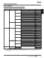
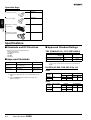
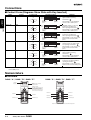
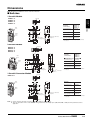
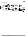
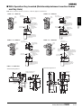
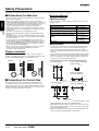
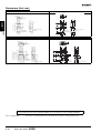
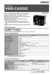
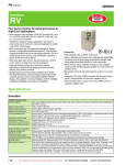
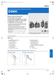
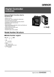
Safety-door Switch
D4NS
Safety Door
Switches
Multi-contact, Labor-saving, Environmentfriendly, Next-generation Safety-door Switch
D4NS
• Lineup includes three contact models with 2NC/1NO and 3NC
contact forms and MBB models in addition to the previous
contact forms 1NC/1NO, and 2NC.
• M12-connector models are available, saving on labor and
simplifying replacement.
• Standardized gold-clad contacts provide high contact reliability.
• Applicable to both standard loads and microloads.
• Free of lead, cadmium, and hexavalent chrome, reducing the
burden on the environment.
Note: Be sure to read the “Safety Precautions” on page A-12 and the
“Precautions for All Safety Door Switches” on page A-2.
Model Number Structure
■ Model Number Legend
Switch
Operation Key
D4NS-@@@
D4DS-K@
1 2 3
1
1. Conduit/Connector size
1: Pg13.5 (1-conduit)
2: G1/2 (1-conduit)
3: 1/2-14NPT (1-conduit)
4: M20 (1-conduit)
5: Pg13.5 (2-conduit)
6: G1/2 (2-conduit)
7: 1/2-14NPT compatible (2-conduit model with M20 conduit size
includes an M20-to-1/2-14NPT conversion adapter)
8: M20 (2-conduit)
9: M12 connector (1-conduit)
2. Built-in Switch
A: 1NC/1NO (slow-action)
B: 2NC (slow-action)
C: 2NC/1NO (slow-action)
D: 3NC (slow-action)
E: 1NC/1NO (MBB contact)
F: 2NC/1NO (MBB contact)
Note: An order for the head part or the switch part alone cannot be
accepted. The Operation Key is sold separately.
A-4
Safety-door Switch
D4NS
1. Operation Key Type
1: Horizontal mounting
2: Vertical mounting
3: Adjustable mounting (Horizontal)
5: Adjustable mounting (Horizontal/ Vertical)
Ordering Information
■ List of Models
Switches (Operation Keys are sold separately.)
Type
Contact configuration
Slow-action
1NC/1NO
2NC
3NC
Slow-action MBB contact 1NC/1NO
2NC/1NO
2-Conduit
Slow-action
1NC/1NO
2NC
2NC/1NO
3NC
Slow-action MBB contact 1NC/1NO
2NC/1NO
1-Conduit, with
connector
Slow-action
1NC/1NO
Model
D4NS-1AF
G1/2
D4NS-2AF
1/2-14NPT
D4NS-3AF
M20
D4NS-4AF
Pg13.5
D4NS-1BF
G1/2
D4NS-2BF
1/2-14NPT
D4NS-3BF
M20
D4NS-4BF
Pg13.5
D4NS-1CF
G1/2
D4NS-2CF
1/2-14NPT
D4NS-3CF
M20
D4NS-4CF
Pg13.5
D4NS-1DF
G1/2
D4NS-2DF
1/2-14NPT
D4NS-3DF
M20
D4NS-4DF
Pg13.5
D4NS-1EF
G1/2
D4NS-2EF
1/2-14NPT
D4NS-3EF
M20
D4NS-4EF
Pg13.5
D4NS-1FF
G1/2
D4NS-2FF
1/2-14NPT
D4NS-3FF
M20
D4NS-4FF
Pg13.5
D4NS-5AF
G1/2
D4NS-6AF
M20, includes M20-to-1/2-14NPT conversion adapter
D4NS-7AF
M20
D4NS-8AF
Pg13.5
D4NS-5BF
G1/2
D4NS-6BF
M20, includes M20-to-1/2-14NPT conversion adapter
D4NS-7BF
M20
D4NS-8BF
Pg13.5
D4NS-5CF
G1/2
D4NS-6CF
M20, includes M20-to-1/2-14NPT conversion adapter
D4NS-7CF
M20
D4NS-8CF
Pg13.5
D4NS-5DF
G1/2
D4NS-6DF
M20, includes M20-to-1/2-14NPT conversion adapter
D4NS-7DF
M20
D4NS-8DF
Pg13.5
D4NS-5EF
G1/2
D4NS-6EF
M20, includes M20-to-1/2-14NPT conversion adapter
D4NS-7EF
M20
D4NS-8EF
Pg13.5
D4NS-5FF
G1/2
D4NS-6FF
M20, includes M20-to-1/2-14NPT conversion adapter
D4NS-7FF
M20
D4NS-8FF
M12 connector
D4NS-9AF
2NC
D4NS
2NC/1NO
Conduit opening/Connector
Pg13.5
Safety Door
Switches
1-Conduit
D4NS-9BF
Slow-action MBB contact 1NC/1NO
D4NS-9EF
Note: 1. The recommended models for equipment and machinery being exported to Europe are those with an M20 or Pg13.5 conduit sizes, and for North
America, the recommended models are those with a 1/2-14NPT conduit sizes.
2. Resin is used as the material for the D4NS housing and head. Use the metal D4BS Safety-door Switch for applications requiring greater
mechanical strength.
Safety-door Switch
D4NS
A-5
Operation Keys
Type
Model
D4DS-K1
Horizontal mounting
D4DS-K2
Vertical mounting
Safety Door
Switches
D4DS-K3
Adjustable mounting
(Horizontal)
D4NS
D4DS-K5
Adjustable mounting
(Horizontal/Vertical)
Specifications
■ Standards and EC Directives
• Conforms to the following EC Directives:
Machinery Directive
Low Voltage Directive
EN50047
EN1088
GS-ET-15
TÜV (EN60947-5-1), CCC (GB14048.5)
Item
TÜV Product
Service
Standard
EN60947-5-1 (approved
direct opening)
Utilization
category
Rated operating current (Ie)
■ Approved Standards
Agency
■ Approved Standard Ratings
AC-15
DC-13
3A
0.27 A
Rated operating voltage (Ue) 240 V
250 V
(See note 1.)
Note: Use a 10-A fuse type gI or gG that conforms to IEC60269 as a
short-circuit protection device. This fuse is not built into the
Switch.
UL/CSA (UL508, CSA C22.2 No. 14)
File No.
UL (See note.)
UL508, CSA C22.2 No.14
E76675
CQC (CCC)
GB14048.5
2003010305077
330
Note: 1. Consult your OMRON representative for details.
2. Approval for CSA C22.2 No. 14 is authorized by the UL
mark.
3. Ask your OMRON representative for information on
approved models.
A300
Rated
voltage
120 VAC
Carry current
Current
Make
10 A
240 VAC
Break
60 A
6A
30 A
3A
Volt-amperes
Make
Break
7,200 VA 720 VA
Q300
Rated
voltage
125 VDC
250 VDC
A-6
Safety-door Switch
D4NS
Carry current
Current
Make
2.5 A
Break
0.55 A
0.55 A
0.27 A
0.27 A
Volt-amperes
Make
69 VA
Break
69 VA
■ Characteristics
Degree of protection (See note 3.)
IP67 (EN60947-5-1)
(This applies for the Switch only. The degree of protection for the key hole is IP00.)
Durability
(See note 4.)
Mechanical
1,000,000 operations min.
Electrical
500,000 operations min. for a resistive load of 3 A at 250 VAC (See note 5.)
300,000 operations min. for a resistive load of 10 A at 250 VAC
0.05 to 0.5 m/s
Operating frequency
30 operations/minute max.
Direct opening force (See note 6.)
60 N min.
Direct opening travel (See note 6.)
10 mm min.
Safety Door
Switches
Operating speed
25 mΩ max. (initial value)
Minimum applicable load (See note 7.)
Resistive load of 1 mA at 5 VDC (N-level reference value)
Rated insulation voltage (Ui)
300 V
Protection against electric shock
Class II (double insulation)
Pollution degree (operating environment)
3 (EN60947-5-1)
Impulse withstand voltage (EN60947-5-1)
Between terminals of the same polarity
2.5 kV
Between terminals of different polarities
4 kV
Between other terminals and uncharged metallic parts
6 kV
Insulation resistance
100 MΩ min.
Contact gap
2 x 2 mm min
Vibration resistance
Malfunction
10 to 55 Hz, 0.75-mm single amplitude
Shock resistance
Destruction
1,000 m/s2 min.
Malfunction
D4NS
Contact resistance
300 m/s2 min.
Conditional short-circuit current
100 A (EN60947-5-1)
Rated open thermal current (Ith)
10 A (EN60947-5-1)
Ambient temperature
Operating:−30°C to 70°C with no icing
Ambient humidity
Operating:95% max.
Weight
Approx. 96 g (D4NS-1CF)
Note: 1. The above values are initial values.
2. The Switch contacts can be used with either standard loads or microloads. Once the contacts have been used to switch a load, however,
they cannot be used to switch smaller loads. The contact surfaces will become rough once they have been used and contact reliability
for smaller loads may be reduced.
3. The degree of protection is tested using the method specified by the standard (EN60947-5-1). Confirm that sealing properties are
sufficient for the operating conditions and environment beforehand. Although the switch box is protected from dust or water penetration,
do not use the D4NS in places where foreign material may enter through the key hole on the head, otherwise Switch damage or
malfunctioning may occur.
4. The durability is for an ambient temperature of 5°C to 35°C and an ambient humidity of 40% to 70%. For more details, consult your
OMRON representative.
5. If the ambient temperature is greater than 35°C, do not pass the 3-A, 250-VAC load through more than 2 circuits.
6. These figures are minimum requirements for safe operation.
7. This value will vary with the switching frequency, environment, and reliability level. Confirm that correct operation is possible with the
actual load beforehand.
Safety-door Switch
D4NS
A-7
Connections
■ Contact Form (Diagrams Show State with Key Inserted)
Model
D4NS-@A@
Contact
Contact form
1NC/1NO
11-12
33-34
Zb
Safety Door
Switches
D4NS-@B@
11
12
33
34
2NC
D4NS
11
12
31
32
2NC/1NO
Zb
11
12
21
22
33
D4NS-@D@
34
3NC
Zb
D4NS-@E@
11
12
21
22
31
32
1NC/1NO MBB
D4NS-@F@
11
12
33
34
2NC/1NO MBB
Stroke
Extraction
completion
position
Operation
Key insertion
completion
position
Stroke
Operation
Key insertion
completion
position
Extraction
completion
position
11-12
21-22
33-34
ON
Stroke
Extraction
completion
position
Operation
Key insertion
completion
position
11-12
21-22
31-32
ON
Stroke
Operation
Key insertion
completion
position
Zb
11
12
21
22
33
34
Stroke
Extraction
completion
position
11-12
21-22
33-34
Stroke
Extraction
completion
position
Only NC contacts 11-12 and
21-22 have an approved
direct opening mechanism.
The terminals 11-12, 21-22, and
33-34 can be used as unlike
poles.
Only NC contacts 11-12, 21-22,
and 31-32 have an approved direct opening mechanism.
Only NC contacts 11-12 have an
approved direct opening
mechanism.
The terminals 11-12 and 33-34
can be used as unlike poles.
ON
Operation
Key insertion
completion
position
Only NC contacts 11-12 and
31-32 have an approved
direct opening mechanism.
The terminals 11-12 and 31-32
can be used as unlike poles.
The terminals 11-12, 21-22, and
31-32 can be used as unlike
poles.
Extraction
completion
position
ON
Operation
Key insertion
completion
position
Only NC contacts 11-12 have an
approved direct opening
mechanism.
The terminals 11-12 and 33-34
can be used as unlike poles.
ON
11-12
33-34
Zb
Remarks
ON
11-12
31-32
Zb
D4NS-@C@
Operating pattern
Only NC contacts 11-12 and
21-22 have an approved direct
opening mechanism.
The terminals 11-12, 21-22 and
33-34 can be used as unlike poles.
Note: MBB (Make Before Break) contacts have an overlapping structure, so that before the normally closed contact (NC) opens, the normally open
contact (NO) closes.
Nomenclature
■ Structure
D4NS-@A@, D4NS-@B@, D4NS-@E@
Operation
key hole
D4NS-@C@, D4NS-@D@, D4NS-@F@
Head
The head can be mounted
in four directions.
Sealing properties
The switch casing ensures IP67
(except the keyhole, which
ensures IP00). Use the D4NS in
places where the keyhole is free
from oil, water, and metal chips.
Terminal 11
Terminal 12
Terminal 31 (33)
Terminal 32 (34)
Terminal 11
Terminal 12
Terminal 21
Terminal 22
Terminal 31 (33)
Terminal 32 (34)
Note: The 2-conduit models have the same terminal arrangement.
A-8
Safety-door Switch
D4NS
Dimensions
Note: All units are in millimeters unless otherwise indicated.
■ Switches
1-Conduit Models
Head cap
Safety Door
Switches
D4NS-1@F
D4NS-2@F
D4NS-3@F
D4NS-4@F
7.5
30.6
15.5
30.2
15.3
Red
D4NS-1@F
D4NS-2@F
D4NS-3@F
D4NS-4@F
Key insertion force
Key extraction force
15 N max.
30 N max.
D4NS
4.4
Operating
characteristics
41 33.5
Pretravel (PT)
6±3 mm
2.5
Black
55
47±0.2
Total travel (TT)
21.5
20±0.1
22±0.1
31.5
2.15±0.05R
mounting holes
4+0.15
0
Two,
depth: 5
dia. holes
(28 mm)
Direct opening force*
Direct opening stroke*
60 N min.
10 mm min.
* Always maintain the above operating characteristics
for safe use.
14.2
30
22±0.2
31
2-Conduit Models
Head cap
D4NS-5@F
D4NS-6@F
D4NS-7@F
D4NS-8@F
7.5
31.5
30.6
21.5
42±0.1
40±0.1
30.2
15.3
Red
41
D4NS-5@F
D4NS-6@F
D4NS-7@F
D4NS-8@F
Key insertion force
Key extraction force
15 N max.
30 N max.
15.5
4.4
Black
Operating
characteristics
33.5 5.4
2.5
9±0.2
Pretravel (PT)
6±3 mm
Total travel (TT)
47
(28 mm)
20.5
20±0.1
39±0.2
25 dia.
22±0.1
Direct opening force*
Direct opening stroke*
Cap
42±0.2
56 max.
2.15±0.05R
mounting holes
14.2
3
30
Two, 4+0.15
dia. holes
0
depth: 5
60 N min.
10 mm min.
* Always maintain the above operating characteristics
for safe use.
1-Conduit Connector Models
Head cap
D4NS-9@F
7.5
Red
30.6
15.5
30.2
15.3
4.4
Black
Operating
characteristics
D4NS-9@F
Key insertion force
Key extraction force
15 N max.
30 N max.
41 33.5
Pretravel (PT)
6±3 mm
2.5
55
47±0.2
31.5
2.15±0.05R
mounting holes
(28 mm)
Total travel (TT)
21.5
20±0.1
22±0.1
4+0.15
0
Two,
depth: 5
dia. holes
Direct opening force*
Direct opening stroke*
60 N min.
10 mm min.
* Always maintain the above operating characteristics
for safe use.
(14)
22±0.2
31
M12 × 1
14.2
30
Note: 1. Unless otherwise specified, a tolerance of ±0.4 mm applies to all dimensions.
2. There are fluctuations in the contact ON/OFF timing for Switches with multiple poles (2NC, 2NC/1NO, or 3NC). Confirm performance before
application.
Safety-door Switch
D4NS
A-9
■ Operation Keys
Note: Unless otherwise specified, a tolerance of ±0.4 mm applies to all dimensions.
D4DS-K1
17.5
28
15
4
13
4.3
7
30
14
D4DS-K3
28
15
Safety Door
Switches
Four, 2.15R
7
30
13
13
Black
4.5 dia.
10.5
9
D4NS
30
6
28
D4DS-K5
7
13
20.9
28
15
Safety-door Switch
7
17
15
4.5
8
30
13
Four, 2.15R
D4NS
Mounting Holes
15°
Black
A-10
8 dia.
24.6
22.5
4
41
2 4.3
56
9 dia.
2
6.3
D4DS-K2
40
20°
18°
43
55
41
6.5
18
(7)
43
■ With Operation Key Inserted (Relationship between Insertion Radius
and Key Hole)
Note: Unless otherwise specified, a tolerance of ±0.4 mm applies to all dimensions.
D4NS-1@F + D4DS-K1
D4NS-1@F + D4DS-K2
44 to 46.5
Key insertion face
Red
40 to 42.5
Key insertion face
Red
(30.6)
(15)
Black
(15)
Black
(30.6)
Permissible difference
in center lines between
the Operation Key and
key hole is ±1.
(30.6)
40 to 42.5
Key insertion face
Vertical key
insertion radius
R ≥ 200
(33.5)
(27.5)
(33.5)
Permissible difference
in center lines between
the Operation Key and
key hole is ±1.
Permissible difference
in center lines between
the Operation Key and
key hole is ±1.
D4NS-1@F + D4DS-K3
D4NS-1@F + D4DS-K5
45 to 47.5
Key insertion face
Red
D4NS
Permissible difference
in center lines between
the Operation Key and
key hole is ±1.
Vertical key
insertion radius
R ≥ 200
44 to 46.5
Key insertion face
Horizontal key
insertion radius
R ≥ 200
(30.6)
Safety Door
Switches
Horizontal key
insertion radius
R ≥ 200
(30.6)
(30.6)
(43±0.1)
(41±0.1)
(40±0.15)
Black
51.9 to 54.4
Key insertion face
Red
Horizontal key
insertion radius
R ≥ 50
Black
Horizontal key
insertion radius
R ≥ 50
Permissible difference
in center lines between
the Operation Key and
key hole is ±1.
(30.6)
45 to 47.5
Key insertion face
Permissible difference
in center lines between
the Operation Key and
key hole is ±1.
(30.6)
Vertical key
insertion radius
R ≥ 200
Vertical key
insertion radius
R ≥ 50
51.9 to 54.4
Key insertion face
(33.5)
(33.5)
Permissible difference
in center lines between
the Operation Key and
key hole is ±1.
Permissible difference
in center lines between
the Operation Key and
key hole is ±1.
D4NS-1@F + D4NS-SK01
Switch Mounting Pattern 2
Switch Mounting Pattern 1
85
65
3
28
3
3
Assembled
Two, M4×6
with D4NS
(included with
product)
3
Assembled
with D4NS
10
74 max.
Receptacle bracket
(included with product)
26
44
58
28
40
65
55
42
39.5
55
40
39.5
20
45.5
42.5
Auxiliary mounting bracket
(included with product)
74 max.
70
42
60
60
40
(Stroke)
30
45
51
19.5
30
45
Safety-door Switch
D4NS
A-11
Safety Precautions
Refer to the “Precautions for All Switches” on page I-2 and “Precautions for All Safety Door Switches” on page A-2.
■ Precautions for Safe Use
Safety Door
Switches
D4NS
• Never disassemble or modify your D4NS in any way, or the D4NS
will not operate normally.
• Do not use the Switch submersed in oil or water or in locations
continuously subject to splashes of oil or water. Doing so may result
in oil or water entering the Switch. (The IP67 degree of protection of
the Switch specifies the amount of water penetration after the
Switch is submerged in water for a certain period of time.)
• Although the switch body is protected from the ingress of dust or
water, avoid the ingress of foreign substance through the key hole
on the head.
Otherwise, accelerated wear or breaking may result.
• Always be sure that the power supply is turned OFF while wiring
the Switch.
• Always attach the cover after completing wiring and before using
the Switch. Electric shock may occur if the Switch is used without
the cover attached.
• Connect a fuse in series with the D4NS to protect it from shortcircuit damage. The value of the breaking current of the fuse must
be calculated by multiplying the rated current by 150% to 200%.
When using the D4NS for an EN rating, use a 10-A fuse of type gI
or gG that complies with IEC 60269.
• When switching general loads (250 VAC/3 A), do not operate two
circuits or more at the same time. Otherwise, insulation
performance may be degraded.
Stopper Installation
Do not use a Switch as a stopper. Be sure to install a stopper as
shown in the following illustration when mounting the Switch so that
the base of the Operation Key does not strike the Head.
Correct
Stopper
Incorrect
Mounting Method
Tightening Torque
Loose screws may result in malfunction. Tighten the screws to the
specified torques.
Terminal screw
0.6 to 0.8 N·m
Cover clamping screw
0.5 to 0.7 N·m
Head clamping screw
0.5 to 0.6 N·m
Operation Key clamping screw
2.4 to 2.8 N·m
Body clamping screw
0.5 to 0.7 N·m
Conduit mounting connection and M12
adaptor
1.8 to 2.2 N·m
(except 1/2-14NPT)
1.4 to 1.8 N·m
(1/2-14NPT)
Cap screw
1.3 to 1.7 N·m
Mounting Holes
• Use M4 screws and washers to mount the Switch and Operation
Key, and tighten the screws to the proper tightening torque. For
safety, use screws that cannot be easily removed or a similar
means to prevent the Switch and Operation Key from being easily
removed.
• As shown below, two studs with a maximum height of 4.8 mm and a
diameter of 4 −−0.05
0.15 mm can be provided, the studs inserted into the
holes on the bottom of the Switch, and the Switch secured at four
locations to increase the mounting strength.
Switch Mounting Holes and Studs Operation Key Mounting Holes
• 1-Conduit Modules
• Horizontal/Vertical Mounting
(D4DS-K1/-K2)
Two, M4
Two, M4
2.5±0.1
20±0.1
22±0.1
Operation key
15±0.1
47±0.1
• Horizontal Adjustable
Mounting (D4DS-K3)
Switch
Two, M4
■ Precautions for Correct Use
The Switch contacts can be used with either standard loads or
microloads. Once the contacts have been used to switch a load,
however, they cannot be used to switch smaller loads. The contact
surfaces will become rough once they have been used and contact
reliability for smaller loads may be reduced.
22±0.1
• 2-Conduit Modules
4 -0.05
-0.15 dia.
Height: 4.8 max.
Two, M4
40±0.1
• Horizontal/Vertical Adjustable
Mounting (D4DS-K5)
Two, M4
2.5±0.1
5.35±0.1
39±0.1
41±0.1 or, 43±0.1
20±0.1
22±0.1
40±0.1
42±0.1
42±0.1
4 -0.05
-0.15 dia.
Height: 4.8 max.
• Use the designated OMRON Operation Key with the Switch. Using
another Operation Key may result in Switch damage.
• Set the Operation Key so that it is within 1 mm of the center of the
key hole. If the Operation Key is offset or at an angle, accelerated
wear or breaking may result.
• Observe the specified insertion radius for the Operation Key and
insert it in a direction perpendicular to the key hole.
A-12
Safety-door Switch
D4NS
Head Direction
Contact Arrangement
• The rotation of the Switch head may be adjusted to any of the four
directions by loosening the head clamping screws at the four
corners of the head. Make sure that no foreign materials enter
through the head.
• When changing the direction of the head, do so while the Operation
Key is inserted.
• The following show a safety contact and an auxiliary contact for 3
contacts and 2 contacts types.
Securing the Door
D4NS-@DF (3NC)
D4NS-@CF (2NC/1NO)
D4NS-@FF (2NC/1NO (MBB))
Zb
Zb
11
12
11
21
22
21
22
31
32
33
34
D4NS-@BF (2NC)
12
Safety Door
Switches
When the door is closed (with the Operation Key inserted), it may be
pulled beyond the set zone because of, for example, the door’s
weight, or the door cushion rubber. Also, if a load is applied to the
Operation Key, the door may fail to unlock properly. Use hooks to
ensure that the door stays within the set zone.
(Screw terminal type)
D4NS-@AF (1NC/1NO)
D4NS-@EF (1NC/1NO (MBB))
Zb
Zb
11
12
11
12
31
32
33
34
D4NS
Set zone
(0.5 to 3 mm)
D4NS-9BF (2NC)
Zb
(Connector type)
1
Operation Key
2
4
3
Wiring
• When connecting with insulation tubes and M3.5 crimp terminals,
connect the terminals as shown in the following figure and wire
without overriding to the case and the cover. Adequate conductor
size is AWG 20 to AWG18 (0.5 to 0.75 mm2).
Prepare lead wires using the lengths given in the following
diagrams. If lead wires are too long, they will press against the
cover causing the cover to not close properly.
B
C
D
E
C
21 22
D
E
33 34
F
F
42 mm
33 mm
28 mm
Tolerance ±2 mm
2-Conduit Models with 3 Poles
ECA
A
Left hand
B
11 12
ECA
D
21 22
42 mm
E
42 mm
28 mm
F
33 34
28 mm
Tolerance ±2 mm
Tolerance ±2 mm
• Do not push the crimp terminal and the likes into the opening
between the parts to prevent the case from being broken and
deformed.
• Use terminals having the thickness of 0.5 mm or less to avoid the
contact between the terminal and the Switch case inside.
The terminals listed below have thickness of 0.5 mm or less.
Manufacture
J.S.T. Mfg Co.
Zb
1 (11)
2 (12)
3 (33)
4 (34)
Pin No. (Terminal No.)
Suitable socket is Type XS2F (OMRON).
• Refer to the Connector Catalog for corresponding Socket pin
numbers and lead wire colors.
Conduit Opening
BD F
Right hand
BD F
C
4 (32)
D4NS-9AF (1NC/1NO)
D4NS-9EF (1NC/1NO (MBB))
• Turn the tightening screws on the Socket by hand and tighten them
until the gap between the Socket and Plug essentially disappears.
• Make sure, however, that the Socket’s connector is tightened
securely, otherwise the rated degree of protection (IP67) of the
D4NS may not be maintained. Furthermore, the Socket connector
may be loosened by vibration.
AB
11 12
2 (12)
3 (31)
Socket Tightening (Models with Connectors)
1-Conduit Models with 3 Poles
A
1 (11)
Type
• When using 1/2-14NPT conduits, apply sealing tape between the
connector and conduit opening to maintain the degree of protection
(IP67) of the Switch.
• Use cables with suitable diameters for the connector being used.
• When wiring, place the enclosed cap screw on unused conduit
openings (for 2-Conduit Switches) and tighten them to the suitable
tightening torque.
Applicable lead wire
size
FV0.5-3.7 (F type)
AWG20 (0.5 mm2)
V0.5-3.7 (straight type)
J.S.T is a Japanese manufacturer.
Terminal screw
L
t:
dz dia.:
D dia.:
B:
L:
F:
I:
0.5 mm
3.7 mm
2.9 mm
6.6 mm
19 mm D dia.
7.7 mm
8.0 mm
l
F
B
Crimp terminal
Correct
Incorrect
dz dia.
Safety-door Switch
D4NS
A-13
Recommended Connectors
Use the connector with thread section of 9 mm long or less. In the
case of the connector with longer thread section, protruded part may
interfere with the other parts inside the body. Use below listed
connector to secure IP67.
Size
Manufacture
Type
Adequate cable
diameter
Safety Door
Switches
D4NS
G1/2
LAPP
ST-PF1/2
5380-1002
6.0 to 12.0 mm
Pg13.5
LAPP
S-13.5
5301-5030
6.0 to 12.0 mm
M20
LAPP
ST-M20 × 1.5
5311-1020
7.0 to 13.0 mm
1/2-14NPT
LAPP
ST-NPT1/2
5301-6030
6.0 to 12.0 mm
When use LAPP's products, use together with a Seal Packing which
is sold separately (Type names, JPK-16, GP-13.5, GPM20. GPM12
is for M12 connector) and tighten with proper tightening torque.
LAPP is a German manufacturer.
Before using the 2 conduit type 1/2-14NPT connector, attach the
appended changing adapter to the Switch, and wind the seal tape
about the joint of the adapter and Switch.
When use M12 conduit type, connect the above listed connector,
after tightened the M12 changing adaptor to the Switch.
A-14
Safety-door Switch
D4NS
Production Discontinuation
Following the release of the D4NS, production of the D4DS will be discontinued.
Date of Production Discontinuation
Production of the D4DS Series will be discontinued as of the end of
March 2006.
D4DS-K1
D4DS-K2
D4DS-K3
D4DS-K5
Safety Door
Switches
Date of Substitute Product Release
Operation Key
•
•
•
•
All of the above Operation Keys can be used with the D4NS.
Sale of the D4NS Series commenced in July 2003.
Product Replacement
D4NS
1. Dimensions
The D4DS and D4NS have basically the same structure, and use
the same mounting method, Operation Keys, mounting hole and
Operation Key insertion positions. The multi-contact structure and
the extra 4 mm in length, however, are different.
2. Terminal Numbers
For the 2-contact model, the terminals 21, 22, 23, and 24 on the
D4DS are 31, 32, 33, and 34 on the D4NS.
3. Recommended Terminals
If the recommended terminals are not used, the Switch may not
be compatible. Make sure that the Switch is compatible with the
terminals.
Comparison of the D4DS and
Substitute Products
Model
D4NS-@
Switch color
Very similar
Dimensions
Very similar
Wiring/connection
Significantly different
Mounting method
Completely compatible
Ratings/performance
Very similar
Operating characteristics
Very similar
Operating method
Completely compatible
List of Recommended Substitute
Products
Switch
D4DS product
Recommended substitute product
D4DS-15FS
D4NS-1AF
D4DS-25FS
D4NS-2AF
D4DS-35FS
D4NS-3AF
D4DS-55FS
D4NS-5AF
D4DS-65FS
D4NS-6AF
D4DS-1AFS
D4NS-1BF
D4DS-2AFS
D4NS-2BF
D4DS-3AFS
D4NS-3BF
D4DS-5AFS
D4NS-5BF
D4DS-6AFS
D4NS-6BF
Safety-door Switch
D4NS
A-15
Dimensions (Unit: mm)
Discontinued Models (1-Conduit D4DS)
Replacement Products (1-Conduit D4NS)
Head cap
7.5
30.6
15.5
30.2
15.3
Safety Door
Switches
4.4
41 33.5
2.5
55
47±0.2
21.5
20±0.1
22±0.1
31.5
D4NS
2.15±0.05R
mounting holes
14.2
30
22±0.2
31
Discontinued Model (2-Conduit D4DS)
Two, 4+0.15
dia. holes
0
depth: 5
Replacement Products (2-Conduit D4NS)
Head cap
7.5
31.5
30.6
21.5
42±0.1
40±0.1
30.2
15.3
15.5
4.4
41
47
33.5 5.4
39±0.2
2.5
20±0.1
22±0.1
9±0.2
20.5
25 dia.
Cap
42±0.2
56 max.
2.15±0.05R
mounting holes
3
14.2
30
Two, 4+0.15
dia. holes
0
depth: 5
ALL DIMENSIONS SHOWN ARE IN MILLIMETERS.
To convert millimeters into inches, multiply by 0.03937. To convert grams into ounces, multiply by 0.03527.
Cat. No. C128-E1-03A
A-16
In the interest of product improvement, specifications are subject to change without notice.
Safety-door Switch
D4NS
Terms and Conditions of Sale
1. Offer; Acceptance. These terms and conditions (these "Terms") are deemed
part of all quotes, agreements, purchase orders, acknowledgments, price lists,
catalogs, manuals, brochures and other documents, whether electronic or in
writing, relating to the sale of products or services (collectively, the "Products")
by Omron Electronics LLC and its subsidiary companies (“Omron”). Omron
objects to any terms or conditions proposed in Buyer’s purchase order or other
documents which are inconsistent with, or in addition to, these Terms.
2. Prices; Payment Terms. All prices stated are current, subject to change without notice by Omron. Omron reserves the right to increase or decrease prices
on any unshipped portions of outstanding orders. Payments for Products are
due net 30 days unless otherwise stated in the invoice.
3. Discounts. Cash discounts, if any, will apply only on the net amount of invoices
sent to Buyer after deducting transportation charges, taxes and duties, and will
be allowed only if (i) the invoice is paid according to Omron’s payment terms
and (ii) Buyer has no past due amounts.
4. Interest. Omron, at its option, may charge Buyer 1-1/2% interest per month or
the maximum legal rate, whichever is less, on any balance not paid within the
stated terms.
5. Orders. Omron will accept no order less than $200 net billing.
6. Governmental Approvals. Buyer shall be responsible for, and shall bear all
costs involved in, obtaining any government approvals required for the importation or sale of the Products.
7. Taxes. All taxes, duties and other governmental charges (other than general
real property and income taxes), including any interest or penalties thereon,
imposed directly or indirectly on Omron or required to be collected directly or
indirectly by Omron for the manufacture, production, sale, delivery, importation, consumption or use of the Products sold hereunder (including customs
duties and sales, excise, use, turnover and license taxes) shall be charged to
and remitted by Buyer to Omron.
8. Financial. If the financial position of Buyer at any time becomes unsatisfactory
to Omron, Omron reserves the right to stop shipments or require satisfactory
security or payment in advance. If Buyer fails to make payment or otherwise
comply with these Terms or any related agreement, Omron may (without liability and in addition to other remedies) cancel any unshipped portion of Products sold hereunder and stop any Products in transit until Buyer pays all
amounts, including amounts payable hereunder, whether or not then due,
which are owing to it by Buyer. Buyer shall in any event remain liable for all
unpaid accounts.
9. Cancellation; Etc. Orders are not subject to rescheduling or cancellation
unless Buyer indemnifies Omron against all related costs or expenses.
10. Force Majeure. Omron shall not be liable for any delay or failure in delivery
resulting from causes beyond its control, including earthquakes, fires, floods,
strikes or other labor disputes, shortage of labor or materials, accidents to
machinery, acts of sabotage, riots, delay in or lack of transportation or the
requirements of any government authority.
11. Shipping; Delivery. Unless otherwise expressly agreed in writing by Omron:
a. Shipments shall be by a carrier selected by Omron; Omron will not drop ship
except in “break down” situations.
b. Such carrier shall act as the agent of Buyer and delivery to such carrier shall
constitute delivery to Buyer;
c. All sales and shipments of Products shall be FOB shipping point (unless otherwise stated in writing by Omron), at which point title and risk of loss shall
pass from Omron to Buyer; provided that Omron shall retain a security interest in the Products until the full purchase price is paid;
d. Delivery and shipping dates are estimates only; and
e. Omron will package Products as it deems proper for protection against normal handling and extra charges apply to special conditions.
12. Claims. Any claim by Buyer against Omron for shortage or damage to the
Products occurring before delivery to the carrier must be presented in writing
to Omron within 30 days of receipt of shipment and include the original transportation bill signed by the carrier noting that the carrier received the Products
from Omron in the condition claimed.
13. Warranties. (a) Exclusive Warranty. Omron’s exclusive warranty is that the
Products will be free from defects in materials and workmanship for a period of
twelve months from the date of sale by Omron (or such other period expressed
in writing by Omron). Omron disclaims all other warranties, express or implied.
(b) Limitations. OMRON MAKES NO WARRANTY OR REPRESENTATION,
EXPRESS OR IMPLIED, ABOUT NON-INFRINGEMENT, MERCHANTABIL-
14.
15.
16.
17.
18.
ITY OR FITNESS FOR A PARTICULAR PURPOSE OF THE PRODUCTS.
BUYER ACKNOWLEDGES THAT IT ALONE HAS DETERMINED THAT THE
PRODUCTS WILL SUITABLY MEET THE REQUIREMENTS OF THEIR
INTENDED USE. Omron further disclaims all warranties and responsibility of
any type for claims or expenses based on infringement by the Products or otherwise of any intellectual property right. (c) Buyer Remedy. Omron’s sole obligation hereunder shall be, at Omron’s election, to (i) replace (in the form
originally shipped with Buyer responsible for labor charges for removal or
replacement thereof) the non-complying Product, (ii) repair the non-complying
Product, or (iii) repay or credit Buyer an amount equal to the purchase price of
the non-complying Product; provided that in no event shall Omron be responsible for warranty, repair, indemnity or any other claims or expenses regarding
the Products unless Omron’s analysis confirms that the Products were properly handled, stored, installed and maintained and not subject to contamination, abuse, misuse or inappropriate modification. Return of any Products by
Buyer must be approved in writing by Omron before shipment. Omron Companies shall not be liable for the suitability or unsuitability or the results from the
use of Products in combination with any electrical or electronic components,
circuits, system assemblies or any other materials or substances or environments. Any advice, recommendations or information given orally or in writing,
are not to be construed as an amendment or addition to the above warranty.
See http://oeweb.omron.com or contact your Omron representative for published information.
Limitation on Liability; Etc. OMRON COMPANIES SHALL NOT BE LIABLE
FOR SPECIAL, INDIRECT, INCIDENTAL, OR CONSEQUENTIAL DAMAGES,
LOSS OF PROFITS OR PRODUCTION OR COMMERCIAL LOSS IN ANY
WAY CONNECTED WITH THE PRODUCTS, WHETHER SUCH CLAIM IS
BASED IN CONTRACT, WARRANTY, NEGLIGENCE OR STRICT LIABILITY.
Further, in no event shall liability of Omron Companies exceed the individual
price of the Product on which liability is asserted.
Indemnities. Buyer shall indemnify and hold harmless Omron Companies and
their employees from and against all liabilities, losses, claims, costs and
expenses (including attorney's fees and expenses) related to any claim, investigation, litigation or proceeding (whether or not Omron is a party) which arises
or is alleged to arise from Buyer's acts or omissions under these Terms or in
any way with respect to the Products. Without limiting the foregoing, Buyer (at
its own expense) shall indemnify and hold harmless Omron and defend or settle any action brought against such Companies to the extent based on a claim
that any Product made to Buyer specifications infringed intellectual property
rights of another party.
Property; Confidentiality. Any intellectual property in the Products is the exclusive property of Omron Companies and Buyer shall not attempt to duplicate it
in any way without the written permission of Omron. Notwithstanding any
charges to Buyer for engineering or tooling, all engineering and tooling shall
remain the exclusive property of Omron. All information and materials supplied
by Omron to Buyer relating to the Products are confidential and proprietary,
and Buyer shall limit distribution thereof to its trusted employees and strictly
prevent disclosure to any third party.
Export Controls. Buyer shall comply with all applicable laws, regulations and
licenses regarding (i) export of products or information; (iii) sale of products to
“forbidden” or other proscribed persons; and (ii) disclosure to non-citizens of
regulated technology or information.
Miscellaneous. (a) Waiver. No failure or delay by Omron in exercising any right
and no course of dealing between Buyer and Omron shall operate as a waiver
of rights by Omron. (b) Assignment. Buyer may not assign its rights hereunder
without Omron's written consent. (c) Law. These Terms are governed by the
law of the jurisdiction of the home office of the Omron company from which
Buyer is purchasing the Products (without regard to conflict of law principles). (d) Amendment. These Terms constitute the entire agreement between
Buyer and Omron relating to the Products, and no provision may be changed
or waived unless in writing signed by the parties. (e) Severability. If any provision hereof is rendered ineffective or invalid, such provision shall not invalidate
any other provision. (f) Setoff. Buyer shall have no right to set off any amounts
against the amount owing in respect of this invoice. (g) Definitions. As used
herein, “including” means “including without limitation”; and “Omron Companies” (or similar words) mean Omron Corporation and any direct or indirect
subsidiary or affiliate thereof.
Certain Precautions on Specifications and Use
1. Suitability of Use. Omron Companies shall not be responsible for conformity
with any standards, codes or regulations which apply to the combination of the
Product in the Buyer’s application or use of the Product. At Buyer’s request,
Omron will provide applicable third party certification documents identifying
ratings and limitations of use which apply to the Product. This information by
itself is not sufficient for a complete determination of the suitability of the Product in combination with the end product, machine, system, or other application
or use. Buyer shall be solely responsible for determining appropriateness of
the particular Product with respect to Buyer’s application, product or system.
Buyer shall take application responsibility in all cases but the following is a
non-exhaustive list of applications for which particular attention must be given:
(i) Outdoor use, uses involving potential chemical contamination or electrical
interference, or conditions or uses not described in this document.
(ii) Use in consumer products or any use in significant quantities.
(iii) Energy control systems, combustion systems, railroad systems, aviation
systems, medical equipment, amusement machines, vehicles, safety equipment, and installations subject to separate industry or government regulations.
(iv) Systems, machines and equipment that could present a risk to life or property. Please know and observe all prohibitions of use applicable to this Product.
NEVER USE THE PRODUCT FOR AN APPLICATION INVOLVING SERIOUS
RISK TO LIFE OR PROPERTY OR IN LARGE QUANTITIES WITHOUT
ENSURING THAT THE SYSTEM AS A WHOLE HAS BEEN DESIGNED TO
2.
3.
4.
5.
ADDRESS THE RISKS, AND THAT THE OMRON’S PRODUCT IS PROPERLY RATED AND INSTALLED FOR THE INTENDED USE WITHIN THE
OVERALL EQUIPMENT OR SYSTEM.
Programmable Products. Omron Companies shall not be responsible for the
user’s programming of a programmable Product, or any consequence thereof.
Performance Data. Data presented in Omron Company websites, catalogs
and other materials is provided as a guide for the user in determining suitability and does not constitute a warranty. It may represent the result of Omron’s
test conditions, and the user must correlate it to actual application requirements. Actual performance is subject to the Omron’s Warranty and Limitations
of Liability.
Change in Specifications. Product specifications and accessories may be
changed at any time based on improvements and other reasons. It is our practice to change part numbers when published ratings or features are changed,
or when significant construction changes are made. However, some specifications of the Product may be changed without any notice. When in doubt, special part numbers may be assigned to fix or establish key specifications for
your application. Please consult with your Omron’s representative at any time
to confirm actual specifications of purchased Product.
Errors and Omissions. Information presented by Omron Companies has been
checked and is believed to be accurate; however, no responsibility is assumed
for clerical, typographical or proofreading errors or omissions.
&RPSOHWH¦7HUPVDQG&RQGLWLRQVRI6DOH§IRUSURGXFWSXUFKDVHDQGXVHDUHRQ2PURQ©VZHEVLWH
DWZZZRPURQFRPRHL¤XQGHUWKH¦$ERXW8V§WDELQWKH/HJDO0DWWHUVVHFWLRQ
$//',0(16,2166+2:1$5(,10,//,0(7(56
7RFRQYHUWPLOOLPHWHUVLQWRLQFKHVPXOWLSO\E\7RFRQYHUWJUDPVLQWRRXQFHVPXOWLSO\E\
20521(/(&7521,&6//&
20521&$1$'$,1&
2QH&RPPHUFH'ULYH
6FKDXPEXUJ,/
)RU86WHFKQLFDOVXSSRUWRURWKHULQTXLULHV
0LOQHU$YHQXH
7RURQWR2QWDULR0%9
2052121/,1(
*OREDOKWWSZZZRPURQFRP
86$KWWSZZZRPURQFRPRHL
&DQDGDKWWSZZZRPURQFD
Cat. No. GCSAFETY-3
10/05
Specifications subject to change without notice
Printed in USA