1
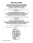
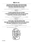
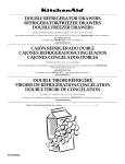
R-107
TECHNICAL EDUCATION
2008 DOUBLE DRAWER
UNDER COUNTER
REFRIGERATOR / FREEZER
PRODUCTS
KDDC24RVS
KDDO24RVX
KDDC24CVS
KDDO24CVX
KDDC24FVS
KDDO24FVX
JUD248RCRS
JUD248RCCX
JUD248CCRS
JUD248CCCR
JUD248FCRS
JUD248FCCX
JOB AID 4317434
FORWARD
This Job Aid “2008 Double Drawer Under Counter Refrigerator / Freezer Products” (Part No.
4317434), provides the In-Home Service Professional with information on the installation, operation, and service of the 2008 Double Drawer Refrigerator / Freezer. For specific information on
the model being serviced, refer to the “Use and Care Guide,” or “Tech Sheet” provided with the
refrigerator / freezer.
The Wiring Diagrams used in this Job Aid are typical and should be used for training purposes
only. Always use the Wiring Diagram supplied with the product when servicing the refrigerator /
freezer.
GOALS AND OBJECTIVES
The goal of this Job Aid is to provide detailed information that will enable the In-Home Service
Professional to properly diagnose malfunctions and repair the 2008 Double Drawer Refrigerator
/ Freezer.
The objectives of this Job Aid are to:
• Successfully troubleshoot and diagnose malfunctions.
• Successfully perform necessary repairs.
• Successfully return the refrigerator / freezer to its proper operational status.
WHIRLPOOL CORPORATION assumes no responsibility for any repairs made
on our products by anyone other than In-Home Service Professionals.
Copyright © 2009, Whirlpool Corporation, Benton Harbor, MI 49022
- ii -
TABLE OF CONTENTS
Page(s)
GENERAL ............................................................................................................................... 1-1
Refrigerator / Freezer Safety.............................................................................................. 1-1
Design Specifications.................................................................................................. 1-2 , 1-3
Model And Serial Number Label Location........................................................................... 1-4
INSTALLATION INFORMATION ............................................................................................ 2-1
Electrical Supply Requirements.......................................................................................... 2-1
Location Requirements....................................................................................................... 2-2
Water Supply Requirments................................................................................................. 2-3
Product Dimensions............................................................................................................ 2-4
THEORY OF OPERATION .................................................................................................... 3-1
Operating Systems..................................................................................................... 3-1 , 3-2
Refrigerator/Freezer Combo Cooling Operation................................................................. 3-3
Refrigerator/Freezer Combo Defrost Operation.................................................................. 3-4
COMPONENT ACCESS ......................................................................................................... 4-1
Drawer Removal................................................................................................................. 4-1
Drawer Installation.............................................................................................................. 4-2
Removing The Drawer Front............................................................................................... 4-3
Removing The User Interface Board................................................................................... 4-4
Installing The User Interface Board..................................................................................... 4-5
Component Locations......................................................................................................... 4-6
Icemaker............................................................................................................................. 4-7
Removing The Separator.................................................................................. 4-8 , 4-9 , 4-10
Evaporator Components....................................................................................................4-11
Machine Compartment Components...................................................................... 4-12 , 4-13
Removing The Water Valve............................................................................................... 4-14
Condenser And PC Board................................................................................................. 4-15
DIAGNOSTICS AND TROUBLESHOOTING . .................................................................. 5-1
Main PCB Connector Function........................................................................... 5-1 , 5-2 , 5-3
Display PCB Connector Function....................................................................................... 5-3
Built-In Board Diagnostics................................................................................................... 5-4
WIRING DIAGRAMS .................................................................................................... 6-1 , 6-2
Product Specifications and Warranty Information Sources................................................. 6-3
- iii -
NOTES
- iv -
GENERAL
REFRIGERATOR / FREEZER SAFETY
Your safety and the safety of others are very important.
We have provided many important safety messages in this manual and on the appliance.
Always read and obey all safety messages.
This is the safety alert symbol.
This symbol alerts you to potential hazards that can kill or hurt you and others.
All safety messages will follow the safety alert symbol and either the word “DANGER” or “WARNING.” These words mean:
WARNING
You can be killed or seriously injured if you don’t
immediately follow instructions.
DANGER
You can be killed or seriously injured if you don’t
follow instructions.
All safety messages will tell you what the potential hazard is, tell you how to reduce the chance
of injury, and tell you what can happen if the instructions are not followed.
1-1
DESIGN SPECIFICATIONS
24" Drawer Models
Double Refrigerator Drawers
Two refrigerator drawers provide additional storage options in the kitchen or other areas of the home.
Euro SeriesI
JUD248RCRS
Overlay - Custom Panels and Handles Required
JUD248RCCX
Refrigerator/Freezer Drawers (with ice maker and water filter)
Upper refrigerator drawer and lower freezer drawer provide additional storage options in the kitchen or other areas of the home
Factory-installed ice maker in lower drawer ensures a constant supply of ice on hand at all times.
Euro Series
JUD248CCRS
Overlay - Custom Panels and Handles Required
JUD248CCCX
Double Freezer Drawers (with ice maker and water filter)
Two freezer drawers provide additional storage options in the kitchen or other areas of the home. Factory-installed ice maker in
lower drawer ensures a constant supply of ice on hand at all times.
Euro Series
JUD248FCRS
Overlay - Custom Panels and Handles Required
JUD248FCCX
1-2
.
DESIGN SPECIFICATIONS (continued)
24" Drawer Models
Double Refrigerator Drawers
Two refrigerator drawers provide additional storage options in the kitchen or other areas of the home.
Architect ® Series II
KDDC24RVS
Overlay - Custom Panels and Handles Required
KDDO24RVX
Refrigerator/Freezer Drawers (with ice maker and water filter)
Upper refrigerator drawer and lower freezer drawer provide additional storage options in the kitchen or other areas of the home .
Factory-installed ice maker in lower drawer ensures a constant supply of ice on hand at all times.
Architect ® Series II
KDDC24CVS
Overlay - Custom Panels and Handles Required
KDDO24CVX
Double Freezer Drawers (with ice maker and water filter)
Two freezer drawers provide additional storage options in the kitchen or other areas of the home. Factory-installed ice maker i n lower
drawer ensures a constant supply of ice on hand at all times.
Architect ® Series II
KDDC24FVS
1-3
Overlay - Custom Panels and Handles Required
KDDO24FVX
MODEL AND SERIAL NUMBER LABEL LOCATION
The Model/Serial Number label location is shown below.
Model and Serial
Number Location
After pulling the upper drawer out, the Model/Serial Number label is on
the inside upper right corner.
1-4
INSTALLATION INFORMATION
ELECTRICAL SUPPLY REQUIREMENTS
Before you move the refrigerator into its final
location, it is important to make sure you have
the proper electrical connection:
• A 115 Volt, 60 Hz, AC only 15- or 20- amp electrical supply, properly grounded in accordance
with the National Electrical Code and local
codes and ordinances, is required.
• It is recommended that a separate circuit,
serving only this appliance, be provided. Use
a receptacle which cannot be turned off by
a switch or pull chain.
WARNING
Electrical Shock Hazard
Plug into a grounded 3 prong outlet.
Do not remove ground prong.
Do not use an adapter.
Do not use an extension cord.
Failure to follow these instructions can
result in death, fire, or electrical shock.
WARNING
Excessive Weight Hazard
Use two or more people to move and
install refrigerator.
Failure to do so can result in back or
other injury.
Recommended Grounding Method
This appliance must be grounded. This appliance is equipped with a power supply cord having a 3-prong grounding plug. The cord must be
plugged into a mating, 3- prong, grounding-type
wall receptacle, grounded in accordance with
the National Electrical Code and local codes
and ordinances. If a mating wall receptacle is
not available, it is the personal responsibility
of the customer to have a properly grounded,
3-prong wall receptacle installed by a qualified
electrician.
2-1
LOCATION REQUIREMENTS
WARNING
WARNING
14 3/4"
(37.5 cm)
A
Explosion Hazard
Keep flammable
materials and vapors,
Do not store fuel tank in a garage or indoors.
such
as gasoline, away from refrigerator
Do not store grill with fuel tank in a garage or indoors.
drawer(s).
Failure to
can result
in death,
Failure
tofollow
do sothese
caninstructions
result in death,
explosion,
explosion, or fire.
or fire.
1/2 "
(1.3 cm)
24"
(60.96 cm)
min.
NOTES:
• For the refrigerator drawers to be flush
with the front of the base cabinets
remove any baseboards or moldings from the rear of the opening. See “Product Dimensions” and later in this section
“Opening Dimensions (both styles).”
B
24" (60.96 cm) min.
Critical Dimensions:
A. 14 3/ 4" (37.5 cm) utility opening
B. 24" (60.96 cm) minimum opening width
• It is recommended that you do not install the refrigerator drawers near an oven, radiator, or other heat source.
• Do not install in a location where the
temperature will fall below 55°F (13°C).
OPENING DIMENSIONS
(BOTH STYLES)
•
34 3/8" (87.3 cm) min.
35" (88.9 cm) max.
Height dimensions are shown with the
leveling legs extended to the minimum height of 1/4" (6.35 mm) below the
refrigerator drawers.
NOTE: When leveling legs are fully extended to 1" (25 mm) below the refrigerator drawers, add 3/4" (19.05 mm) to the
height dimensions.
See “Product Dimensions.”
• If the floor of the opening is not level with
the kitchen floor,
• shim the opening to make it level with the
kitchen floor.
2-2
WATER SUPPLY REQUIREMENTS
WATER PRESSURE
Gather the required tools and parts before
starting installation.
Read and follow the instructions provided with
any tools listed here.
A cold water supply with water pressure of
between 30 and 120 psi (207 and 827 kPa)
is required to operate ice maker. If you have
questions about your water pressure, call a
licensed, qualified plumber.
TOOLS NEEDED:
• Flat-blade screwdriver
• 7/16" open-end wrench
• 1/2" open-end wrench or two adjustable
wrenches
• 1/4" nut driver and drill bit
• Cordless drill and drill bit
Reverse Osmosis Water Supply
IMPORTANT:
The pressure of the water supply coming out
of a reverse osmosis system going to the
water inlet valve of the refrigerator needs to
be between 30 and 120 psi (207 and 827
kPa).
NOTE: Your refrigerator dealer has a kit available with a 1/4" (6.35 mm) saddle-type shutoff
valve, a union, and copper tubing.
Before purchasing, make sure a saddle-type
valve complies with your local plumbing codes.
Do not use a piercing-type or 3/8" (4.76 mm)
saddle valve which reduces water flow and
clogs more easily.
If a reverse osmosis water filtration system
is connected to your cold water supply, the
water pressure to the reverse osmosis system needs to be a minimum of 40 to 60 psi
(276 to 414 kPa). If the water pressure to the
reverse osmosis system is less than 40 to 60
psi (276 to 414 kPa):
•
•
IMPORTANT:
• If you turn the refrigerator on before the water line is connected, turn the ice
maker OFF.
• All installations must meet local plumbing code requirements.
• Use copper tubing and check to make sure there are no leaks Install copper tub
ing only in areas where the household temperatures will remain above freezing.
Check to be sure the sediment filter in the reverse osmosis system is not blocked.
Replace filter if necessary.
Allow the storage tank on the reverse
osmosis system to refill after heavy
usage.
If you have questions about your water
pressure, call a licensed, qualified
plumber.
2-3
PRODUCT DIMENSIONS
STYLES 1 AND 2: ARCHITECT®
SERIES AND OVERLAY
•
•
•
Height dimensions are shown with the leveling legs extended to 1/4" (6.35 mm) below the refrigerator drawers.
When leveling legs are fully extended to 1" (25 mm) below the refrigerator drawers, add 3/4" (19.05 mm) to the height dimensions.
The power cord is 60" (152.4 cm) long
Style 1: Architect ® Series
Style 2: Overlay
14 7/8 "
(37.8 cm)
3/8 "
(1.0 cm)
14 7/8 "
(37.8 cm)
34 1/8 "
(86.7 cm)
3/8 "
(1.0 cm)
34 1/8 "
(86.7 cm)
14 7/8 "
(37.8 cm)
14 7/8 "
(37.8 cm)
2-4
THEORY OF OPERATION
OPERATING SYSTEMS
Normally, this switching between upper and
lower evaporator fans repeats several times
before both temperatures reach below the
set temperature of -4ºF. Once the temperatures of both thermistors reach below the set
temperature of -4ºF, the main PCB shuts off
the compressor and both evaporator fans.
Main PCB will turn off the condenser fan 2
minutes later.
1) General Cooling Operation of the RR (All Refrigerator) and FF (All Freezer)
There is an upper chamber and lower chamber with each chamber having a dedicated
drawer. Even though two chambers are not
physically separated, there is one dedicated
thermistor for each chamber (total of two per
unit) that is located in front of the fan cover.
Each chamber has a dedicated DC evaporator motor (a total of two) that is mounted in
front of the fan cover.
The condenser fan and the compressor will
be turned on again when one of the thermistor temperatures reaches the set temperature 4ºF. In this event the process listed
at the beginning of this section will repeat
before shutting off the compressor again.
A thermistor is used to measure the temperature of each chamber at real sampling
time. This measured temperature is used
to control the operation of the compressor,
DC condenser fan motor and DC evaporator
fan motors as well as to display the chamber
temperature. The displayed temperature,
however; is not the real time temperature; it is
a computed weighted average temperature to
minimize the possible confusion of average
end users.
2) General Cooling Operation of the RF (Combination Unit)
The upper chamber and lower chamber are
physically divided by the center mullion with
each chamber having a dedicated drawer.
As the two chambers are physically and
thermally separated, there is one dedicated
thermistor for each chamber (total of two)
located in front of fan cover. Each chamber
has a dedicated DC evaporator motor (a total
of two). These DC evaporator fan motors are
also mounted in front of the fan cover.
As the usual start up, the main PCB turns on
the condenser fan and after 10 seconds the
compressor will start. The compressor will
continue to run until the temperatures of both
thermistors reach the set temperature -4ºF
(the number 4 is subject to design change).
While the compressor is on, the main PCB
turns only one of two evaporator fans on.
The evaporator fan in the upper chamber
acts as a primary source of air movement of
the both chambers. When the upper thermistor reaches the set temperature of -4ºF, the
upper evaporator fan motor stops, and logic
reads the lower thermistor temperature. If
it is higher than the set temperature of -4ºF,
the main PCB will turn on the lower evaporator fan and continue to run the compressor.
The thermistor is used to measure the temperature of each chamber at real sampling
time. This measured temperature is used
to control the operation of compressor, DC
condenser fan motor and DC evaporator fan
motors as well as to display two chamber
temperatures. The displayed temperature,
however; is not the real time temperature; it is
a computed weighted average temperature to
minimize the possible confusion of average
end users.
3-1
Continued on next page
OPERATING SYSTEMS (continued)
As the usual start up, the main PCB turns
on the condenser fan and after 10 seconds
the compressor will start. The compressor
will continue to run until the temperatures of
both thermistors reach the set temperature
for each chamber of -4ºF (the number 4 is
subject to design change). While the compressor is on, the main PCB turns only one of
the two evaporator fans on. The evaporator
fan in the lower chamber is turned on primarily, as the lower chamber is a freezer (about
0ºF) and the upper chamber is a refrigerator
(4ºF). When the lower thermistor temperature reaches to the freezer set temperature
of -4ºF, the lower evaporator fan motor stops,
and logic reads the upper thermistor temperature. If it is higher than the refrigerator set
temperature of -4ºF the main PCB will turn
on the upper evaporator fan and continue to
run the compressor. Normally, this switching
between upper and lower evaporator fans repeats several times before both temperatures
reach below the set temperature of -4ºF.
Once the temperatures of both thermistors
reach below the set temperature of -4ºF, the
main PCB shuts off the compressor and both
evaporator fans. Main PCB will turn off the
condenser fan 2 minutes later.
If the thermistor temperature of the lower
chamber (freezer) reaches to the freezer set
temperature of 4ºF, the main PCB will turn on
the condenser fan, then the compressor and
the lower evaporator fan (10 seconds later)
regardless to the temperature of the thermistor in the upper chamber. While the compressor is on, the above switching between
two evaporator fans takes place again.
In a rare case (for example, at the beginning
of ice making or the ambient temperature is
very high) when the compressor is on and
the temperature of the lower thermistor is
kept above the freezer set temperature -4ºF
for extended period due to higher then normal demand in the freezer section, the main
logic monitors the temperature of the upper
chamber every 10 minutes or so to make
sure the refrigerator temperature is within
the range. If not, shut off the lower evaporator fan and turn on the upper evaporator fan
until the temperature of the upper thermistor drops to the refrigerator set temperature
-4ºF. Once the upper thermistor temperature
reaches that, the lower evaporator fan will be
switched on.
3) General Defrost Operation (All Models)
When the temperature of the thermistor of
upper chamber (refrigerator) reaches the
refrigerator set temperature of 4ºF, but the
freezer thermistor temperature remains
below the freezer set temperature 4ºF, the
main PCB will turn on the upper evaporator
fan without turning the condenser fan or the
compressor. Basically, cooling logic is using the cold air of the freezer section to cool
the refrigerator section during this period.
If the thermistor temperature of the upper
chamber (refrigerator) reaches the refrigerator set temperature -4ºF while the thermistor
temperature of the lower chamber (freezer)
is still lower than the freezer set temperature
4ºF (and this seems to happen regular basis),
the main PCB will simply turns off the upper
evaporator fan without ever turning the compressor on.
The main PCB has a timer to monitor the accumulated compressor operation time. When
this time reaches certain hours (for example 10
hours), the main PCB will shut off the compressor the evaporator fans, reset the timer, and stop
sampling the temperature. In 30 seconds, the
defrost heater will turn on and the condenser fan
will be turned off 2 minutes after the shut off of
the compressor. The heater will be cut off when
the defrost-sensing thermistor that is mounted
near the top center of the evaporator pipe has
reached the preset temperature (for example
8ºF). (If the defrost-sensing thermistor logic
fails, then the fuse will melt as any redundantly
protected refrigeration system.) Five minutes
after termination of the heater, the main PCB
starts to sample the temperature and the same
cooling function above 1) or 2) resumes.
3-2
REFRIGERATOR/FREEZER COMBO COOLING OPERATION
1. Power On: Compressor, condenser fan
and the freezer evaporator fan turns on. The
refrigerator evaporator fan remains off. The
controller continues to monitor the freezer
temperature sensor (bottom thermistor) until
the bottom sensor temperature (BT) reaches
the freezer set temperature (FST).
compressor stop. Once the compressor is
off, the controller continues to monitor the TT
and BT.
2, When the TT reaches FST-2.78°C, the
controller stops the freezer evaporator fan
and measures the refrigerator temperature
- TT (top thermistor) against the refrigerator set temperature (RST). If the TT > RST,
then the compressor and the condenser fan
remain on while the top evaporator fan turns
on.
If the TT > RST , but the BT < FST, then the
controller turns on top evaporator fan only.
The compressor, condenser fan and bottom
evaporator fan remain off.
The compressor fan, condenser and the
related evaporator fans turns on when the
TT is higher than the RST or the BT is higher
than the FST.
The controller continues to monitor the TT
and BT. If the BT > FST, then the compressor and condenser fan turn on, while the top
evaporator fan continues to run. If the BT
< FST and the TT > RST, then the freezer
evaporator fan turns on (the compressor and
condenser fan remain off as long as BT <
FST).
3. The controller continues to monitor the
TT until the TT < RST, then the refrigerator
evaporator fan motor stops. The controller
checks the BT again, if the BT > FST, the
freezer evaporator fan turns on while the
compressor and condenser fan remain on.
Repeat step 3 until both TT and BT are
below the set temperatures minus differentials (i.e. TT < RST and BT < FST). If both
TT and BT are the below set temperatures
minus differentials, then all the motors and
3-3
REFRIGERATOR/FREEZER COMBO DEFROST CYCLE
The defrost cycle starts after ten hours of
compressor run time.
There is a 5-minute drip time after the defrost
heat is terminated by the defrost sensor.
The condenser fan runs for two minutes after
the compressor stops and the heat starts.
The condenser fan starts when the heat
stops and runs throughout 5-minute drip
time.
The evaporator fans stop immediately.
At the end of the 5-minute drip time, the
compressor starts.
The heater is energized until the defrost sensor (top center of the evaporator) reaches
8F. (There is no set defrost time.)
One minute after the compressor starts, the
evaporator fans start.
A defrost thermal fuse, located in the right
end of the evaporator return cuts out if an
overheat condition occurs.
Count down to the next 10 hours of compressor run time begins, and so forth.
3-4
COMPONENT ACCESS
DRAWER REMOVAL
WARNING
Figure 1
Electrical Shock Hazard
Disconnect power before servicing.
Replace all parts and panels before
operating.
Failure to do so can result in death or
electrical shock.
To remove the top drawer:
1. Open the drawer.
2. Locate the wiring harness on the left side of the drawer, see figure 1. 3. Pull the harness out of the front cover to
expose the connector.
4. Free the harness from the plastic retainer and disconnect the harness, see figures
2 and 3.
Figure 3
Figure 2
Figure 6
Figure 5
Figure 4
5. Depress the spring releases located in the left and right hand slides, see figures 4 and 5. 6. Slide drawer out and set on work surface, see figure 6. 7. Repeat the process to remove the lower drawer.
Note: The lower drawer does not have a wiring harness that must be disconnected. 4-1
DRAWER INSTALLATION
WARNING
Electrical Shock Hazard
Disconnect power before servicing.
Replace all parts and panels before
operating.
Failure to do so can result in death or
electrical shock.
1. Open the lower drawer.
2. Place a piece of cardboard or a blanket on the drawer to shelter it,
see figure 1.
Figure 5
Figure 1
3. Start the upper rail into the slide.
4. Repeat the process on the opposite side,
see figure 2. Figure 2
Figure 3
5. Rest the upper drawer on the
lower drawer. 6. Align the lower
slides to the lower rails.
7. Start the slide onto the rail, see figure 5.
8. Check drawer or Proper fit and seal,
see figure 6.
Figure 6
9. Connect the wiring harness.
10. Install the connector into the drawer front.
11. Attach the harness into the plastic retainer along the side of the drawer,
see figures 3 and 4. Figure 4
4-2
REMOVING DRAWER FRONT, GASKET AND DRAWER HANDLE
Figure 2
Gasket Removal:
The gasket pulls out of a channel in the
drawer front, see figure 2.
Figure 1
1. Remove two screws on both sides of the drawer securing the drawer cover and drawer.
2. Separate the drawer cover from the drawer, see figure 1.
Figure 3
Handle Removal:
1. Remove the inner panel.
2. Remove the two screws securing the handle to the drawer front, see figure 3.
4-3
REMOVING THE USER INTERFACE BOARD
WARNING
Electrical Shock Hazard
Disconnect power before servicing.
Replace all parts and panels before
operating.
Failure to do so can result in death or
electrical shock.
Figure 1
1. Remove the four screws securing the user interface housing to the drawer front,
see figure 1.
Figure 3
3. Remove the insulation between the hous
ing and the user interface board,
see figure 3. 4. Locate and remove the eight screws securing the user interface board to the housing.
NOTE: There are
holes in the housing
to allow access to the
screw heads,
see figure 4.
Figure 4
5. Lift out the user interface board,
see figure 5. Figure 2
2. Separate the housing from the drawer front, see figure 2. Figure 5
4-4
INSTALLING THE USER INTERFACE BOARD
WARNING
Electrical Shock Hazard
Disconnect power before servicing.
Replace all parts and panels before
operating.
Failure to do so can result in death or
electrical shock.
Figure 1
1. Locate the red and white LED lights
located on the user interface board,
see figure 1.
Figure 3
3. Align the LED’s on the user interface board and the slots in the housing.
4. Install the user interface board.
NOTE: Do not force the board into place. If
the LED’s are aligned with the holes in the
housing the board will drop into place, see
figure 3.
Figure 2
5. Install the screws.
6. Install the insulation.
7. Attach the housing to the front cover.
2. Locate the rectangular shaped holes in the housing, see figure 2.
4-5
COMPONENT LOCATIONS
Evaporator Fan
Refrigerator Components
See figure 1.
Refrigerator Thermistor
Door Switch
The side rail and slide
assemblies lift up and
out to remove,
see figure 1.
Wire Harness For User Interface
Figure 1
Freezer Lights
Freezer Thermistor
Evaporator Fan
Door Switch
Modular Ice Maker
Figure 3
4-6
Figure 2
Freezer Components
See figure 3.
ICEMAKER
WARNING
Electrical Shock Hazard
Disconnect power before servicing.
Replace all parts and panels before
operating.
Failure to do so can result in death or
electrical shock.
Figure 2
Icemaker Removal
1. Remove the 2 screws securing the ice maker to the mounting plate, see figure 2.
Figure 3
2. Drop down the ice maker.
3. Disconnect the wiring harness, see figure 3.
Figure 1
A standard 8 cavity modular ice maker is
used on this product and can be tested and
serviced the same as all other modular ice
makers, see figure 1. Figure 4
Figure 5
4. The fill tube can be removed by pulling straight out, see figures 4 and 5. 4-7
REMOVING THE SEPARATOR
2. Push up on the bottom of the separator
from the freezer section to free the
separator from the cabinet, see figure 2.
WARNING
Electrical Shock Hazard
Disconnect power before servicing.
Replace all parts and panels before
operating.
Failure to do so can result in death or
electrical shock.
Figure 3
3. Slide the separator out of the cabinet.
NOTE: The separator can be removed with
the side rails in place but it is easier if the
rails are removed, see figure 3.
Figure 1
1. Remove the two screws securing the separator to the mullion rail, see figure 1.
Figure 4
4. Remove screws around the perimeter of the evaporator cover securing it to the cabinet, see figure 4.
Figure 2
4-8
REMOVING THE SEPARATOR (continued)
Figure 6
Figure 5
5. Drop the evaporator cover down to
access the wiring harness connector
located in the top right hand corner,
see figure 5.
6. Remove the 2 screws on the cover plate and remove, see figure 6. Figure 9
10. After disconnecting the wire harnesses, the evaporator cover can be removed,
see figure 10. Figure 7
Figure 8
7. Disconnect three wiring harnesses,
see figures 7 and 8.
Figure 10
NOTE: There are releases located on the
top of two of the connectors that have to be
depressed to remove the wire harness, see
figure 7. 8. With the three harnesses removed from the block, the evaporator cover can be pulled out to access the remaining harness.
9. Disconnect harness, see figure 9. 4-9
Continued on the next page
REMOVING THE SEPARATOR (continued)
Combo Unit Refrigerator/Freezer
The evaporator cover for the refrigerator/
freezer has insulation tape attached. The
refrigerator cover does not.
Figure 11
The evaporator fan motors and Thermistors
are serviced from the back side of the evaporator cover, see figure 11.
4-10
All Refrigerator
EVAPORATOR COMPONENTS
WARNING
Thermistor Service
Figure 2
Electrical Shock Hazard
Disconnect power before servicing.
Replace all parts and panels before
operating.
Failure to do so can result in death or
electrical shock.
Evaporator Outlet
Evaporator Inlet
Figure 3
Defrost Limiter
The Thermistor clips into the housing, see
figure 2. A piece of foam insulation is installed between the Thermistor and the
evaporator cover, see figure 3. Ice Maker Water Valve and Condenser
Fan Removal
Water Valve
Defrost Heater
Figure 1 The defrost limiter is a one time thermal fuse
that opens in case of an overheat condition,
see figure 1. Figure 4 The ice maker water valve is located behind
the condenser fan motor, see figure 4. 4-11
MACHINE COMPARTMENT COMPONENTS
WARNING
Electrical Shock Hazard
Disconnect power before servicing.
Replace all parts and panels before
operating.
Failure to do so can result in death or
electrical shock.
Figure 1a
Machine Compartment Components
figures 1a, 1b, and 1c.
Figure 2
1. Remove screws securing the drain pan to the top of the machine compartment.
The drain pan can now be removed.
Figure 3
2. The drain trap can be removed by pulling it outofthe
Figure 1b
Figure 1c
Figure 4
The compressor terminal cover can be
popped off to access the starting device,
see figure 4.
4-12
MACHINE COMPARTMENT (continued)
Overload
Relay
12 mfd Run Capacitor
Foam Pad
Overload Removed
Run Capacitor
4-13
REMOVING THE WATER VALVE
WARNING
Electrical Shock Hazard
Disconnect power before servicing.
Replace all parts and panels before
operating.
Failure to do so can result in death or
electrical shock.
Figure 3
3. Remove the fan assembly, see figure 3. Figure 1
1. Remove insulation strip located next to left side of the cabinet, see figure 1.
Screw
Figure 4
3 Screws
4. Remove the screw securing the water valve bracket to the cabinet, see figure 4.
Figure 2
2. Remove three screws securing the condenser fan assembly to the cabinet, see figure 2.
4-14
CONDENSER AND PC BOARD
WARNING
Electrical Shock Hazard
Disconnect power before servicing.
Replace all parts and panels before
operating.
Failure to do so can result in death or
electrical shock.
Figure 1
A metal plate covers the condenser,
see figure 1.
PC Board
Condenser cover removed,
Double Drawer refrigerator
model, see figure 2.
Figure 2
PC Board
Screw
Screw
Figure 3
Remove two screws and drop down the PC board assembly, see figure 3.
This can be done without removing the pan in figure 2. 4-15
NOTES
4-16
DIAGNOSTICS AND TROUBLESHOOTING
MAIN PCB CONNECTOR FUNCTION
WARNING
Electrical Shock Hazard
Disconnect power before servicing.
Replace all parts and panels before
operating.
Failure to do so can result in death or
electrical shock.
J1 J2 J4 J5 J6 J7 J1 Defrost Heater, Thermal Fuse
Ice Maker
Power Supply, Compressor
Display, Lamp
Electrical Parts( Inside Cabinet)
Condenser Fan Motor
Defrost Heater, Thermal Fuse
#1 pin connects to white wire
#3 pin connects to yellow wire
#1 and #3 pins show 120Vac only when defrost mode.
5-1
J2 Ice Maker
#1 pin connects to White wire, Water Valve and Ice Maker.
#2 pin connects to Black wire and Ice Maker.
#3 pin connects to Green/Yellow wire
#1 and #2 pins supply 120Vac if Ice Maker
button on display PCB is turned on.
Continued on the next page.
MAIN PCB CONNECTOR FUNCTION (continued)
J5 Display, Lamp
J4 Power Supply, Compressor
#1 pin connects to Green wire and Frame.
#2 pin connects to Black wire and Power Plug.
#3 pin connects to White wire and Compressor.
#4 pin connects to Yellow wire and Compressor.
#5 pin connects to Red wire and Power Plug.
#2 and #5 pins show 120Vac when a power
plug was connected.
#3 and #4 pins show 120Vac only when a
compressor is on.
#1~#8 These pins go to Display PCB.
#9~#10 These pins go to lower lamp.
#1~#3 Sireal communication lines.
J6 Electrical Parts( Inside Cabinet)
#1~#6 Sensor Lines
#7~#9 Door Switch Lines
#10~#13 Fan Motor Lines
#10(or #11) will be 0V when Upper Fan Motor is working.
#7 and #8 pins are pulled up to 5Vdc by MCU.
These pins will be 0V when door is opened. (Switch is open.)
5-2
MAIN PCB CONNECTOR
FUNCTION (continued)
DISPLAY PCB CONNECTOR
FUNCTION
J7 Condenser Fan Motor
J1 Main PCB
J2 Upper Lamp
J1 Connect to Main PCB
#2 will be 0V when Condesor Fan Motor is working.
#1~#3 Sireal Communication with Main
PCB
#4 #4 will be 0V when Upper lamp is on.(Upper door open)
J1 Connect to Main PCB
#1 #1 will be 0V when Upper lamp is on.
(Upper door open)
5-3
BUILT-IN BOARD DIAGNOSTICS
Test User Interface Display
Energize evaporator fan motors and ice
maker
Press and hold "deg. C" and "-" simultaneously for 5 seconds to start the test mode.
Press "Max Cool" and "-" simultaneously for
three seconds to enter the test mode.
The user interface will blink all of the 7-segment displays.
The LEDs will blink
The evaporator fans and ice maker circuits
will be energized, by-passing the interior light
switches and temperature control sequence.
The filter indicator LED will change color, yellow to red to none
Press "Max Cool" and "-" simultaneously for
three seconds to exit the test mode.
Press and hold "deg. C" and "-" simultaneously for 5 seconds to exit the test mode.
Showroom Floor Display Mode
Press and hold "Cooling On/Off" and "Holiday Mode" for 3 seconds to enter the display
test mode (this one is the most fun).
Defrost Test
Press and hold "Max Cool" and "Holiday"
simultaneously for 3 seconds to start the test
mode.
The cooling system and ice maker will not
operate but he lights and user interface will
be active.
The defrost heater will be energized immediately.
Press and hold "Cooling On/Off" and "Holiday Mode" for 3 seconds to exit the display
test mode
A dot will appear at the right end of the temperature display.
Press and hold "Max Cool" and "Holiday"
simultaneously for 3 seconds to exit the test
mode.
5-4
WIRING DIAGRAMS
6-1
WIRING DIAGRAMS (continued)
6-2
PRODUCT SPECIFICATIONS
AND
WARRANTY INFORMATION SOURCES
IN THE UNITED STATES:
FOR PRODUCT SPECIFICATIONS AND WARRANTY INFORMATION CALL:
FOR WHIRLPOOL PRODUCTS: 1-800-253-1301
FOR KITCHENAID PRODUCTS: 1-800-422-1230
FOR ROPER PRODUCTS: 1-800-447-6737
FOR TECHNICAL ASSISTANCE WHILE AT THE CUSTOMER’S HOME CALL:
THE TECHNICAL ASSISTANCE LINE: 1-800-832-7174
HAVE YOUR STORE NUMBER READY TO IDENTIFY YOU AS AN
AUTHORIZED IN-HOME SERVICE PROFESSIONAL
FOR LITERATURE ORDERS:
PHONE: 1-800-851-4605
FOR TECHNICAL INFORMATION AND SERVICE POINTERS:
www.servicematters.com
IN CANADA:
FOR PRODUCT SPECIFICATIONS AND WARRANTY INFORMATION CALL:
1-800-461-5681
FOR TECHNICAL ASSISTANCE WHILE AT THE CUSTOMER’S HOME CALL:
THE TECHNICAL ASSISTANCE LINE: 1-800-488-4791
HAVE YOUR STORE NUMBER READY TO IDENTIFY YOU AS AN
AUTHORIZED IN-HOME SERVICE PROFESSIONAL