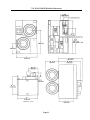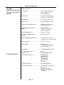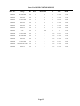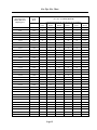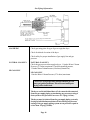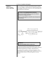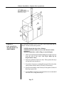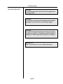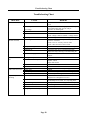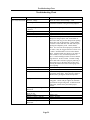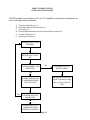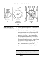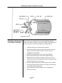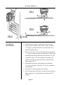
1
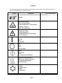
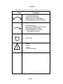
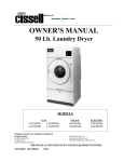
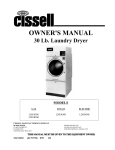
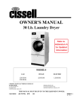
OWNER'S MANUAL
75 lb. HD STACK LAUNDRY DRYER
Gas: Natural and LP
Steam
HD75ST
Cissell Manufacturing Co.
831 S. First St. - P.O.Box 32270 - Louisville, Ky. - 40232-2270
Tel: (502) 587-1292 - Fax: (502) 585-2333 Sales Fax: (502) 585-3625 - Service/Parts Fax: (502) 681-1275
THIS MANUAL MUST BE GIVEN TO THE EQUIPMENT OWNER
Page 1
MANHD75ST 05/02
IMPORTANT NOTICES—PLEASE READ
For optimum efficiency and safety, we recommend that you read the manual before operating the equipment. Store this manual in a
file or binder and keep for future reference.
WARNING: For your safety, the information in this manual must be followed to minimize
the risk of fire or explosion or to prevent property damage, personal injury or loss of life.
- Do not store or use gasoline or other flammable vapors or liquids in the vicinity of this or
any other appliance.
- WHAT TO DO IF YOU SMELL GAS
•
•
•
•
•
Do not try to light any appliance.
Do not touch any electrical switch; do not use any phone in your building.
Clear the room, building or area of all occupants.
Immediately call your gas supplier from a neighbor's phone. Follow the gas supplier's
instructions.
If you cannot reach your gas supplier, call the fire department.
Installation and service must be performed by a qualified installer, service agency or the gas
supplier.
WARNING: In the event the user smells gas odor, instructions on what to do must be posted in a
prominent location. This information can be obtained from the local gas supplier.
WARNING: Wear safety shoes to prevent injuries.
WARNING: Purchaser must post the following notice in a prominent location:
FOR YOUR SAFETY
Do not store or use gasoline or other flammable vapors
and liquids in the vicinity of this or any other appliance.
WARNING: A clothes dryer produces combustible lint and should be exhausted outside the
building. The dryer and the area around the dryer should be kept free of lint.
WARNING: Be safe, before servicing machine, the main power should be shut off.
Page 2
WARNING: To avoid fire hazard, do not dry articles containing foam rubber or similar texture materials.
Do not put into this dryer flammable items such as baby bed mattresses, throw rugs,undergarments
(brassieres, etc.) and other items which use rubber as padding or backing. Rubber easily oxidizes causing
excessive heat and possible fire. These items should be air dried.
WARNING: Synthetic solvent fumes from drycleaning machines create acids when drawn through the
dryer. These fumes cause rusting of painted parts, pitting of bright or plated parts, and completely
removes the zinc from galvanized parts, such as the tumbler basket. If drycleaning machines are in the
same area as the tumbler, the tumbler's make-up air must come from a source free of solvent fumes.
WARNING: Do not operate without guards in place.
WARNING: Check the lint trap often and clean as needed but at least a minimum of once per day.
WARNING: Alterations to equipment may not be carried out without consulting with the factory and
only by a qualified engineer or technician. Only Manufacturer parts may be used.
WARNING: Remove clothes from dryer as soon as it stops. This keeps wrinkles from setting in and
reduces the possibility of spontaneous combustion.
WARNING: Be safe - shut main electrical power and gas supply off externally before attempting
service.
WARNING: Never use drycleaning solvents, gasoline, kerosene, or other flammable liquids in the dryer.
FIRE AND EXPLOSION WILL OCCUR. NEVER PUT FABRICS TREATED WITH THESE LIQUIDS
INTO THE DRYER. NEVER USE THESE LIQUIDS NEAR THE DRYER..
WARNING:Do not place items exposed to cooking oils in your dryer. Items contaminated with cooking
oils may contribute to a chemical reaction that could cause a load to catch fire.
WARNING: Never let children play near or operate the dryer. Serious injury could occur if a child
should crawl inside and the dryer is turned on.
WARNING: Never tumble fiberglass materials in the dryer unless the labels say they are machine
dryable. Glass fibers break and can remain in the dryer. These fibers cause skin irritation if they
become mixed with other fabrics.
WARNING: Before operating gas ignition system - purge air from natural gas or propane gas lines
per manufacturer’s instructions.
WARNING: To reduce the risk of electric shock, disconnect this appliance from the power supply
before attempting any user maintenance other than cleaning the lint trap. Turning the controls to the
OFF position does not disconnect this appliance from the power supply.
Page 3
ATTENTION: L’ACHETEUR DOIT PLACER L’AVERTISSEMENT
SUIVANT DANS UN ENDROIT CLAIR ET VISIBLE:
AVERTISSEMENT. Assurez-vous de bien
suivre les instructions donnees dans cette
notice pour reduire au minimum le risque
d’incendie ou d’explosion ou pour eviter tuot
dommage materiel, toute blessure ou la mort.
__ Ne pas entreposer ni utiliser d’essence ni
d’autres vapeurs ou liquides inflammables dans
le voisinage de cet appareil ou de tout autre
apparell.
__ QUE FAIRE SI VOUS SENTEZ UNE
ODEUR DE GAZ:
• Ne pas tenter d’allumer d’apparell.
• Ne touchez a aucun interrupteur. Ne pas
vous servir des telephones se trouvant dans
le batiment ou vous vous trouvez.
• Evacuez la piece, le batiment ou la zone.
• Appelez immediatement votre fournisseur de
gaz depuis un voisin. Suivez les instructions
du fournisseur.
• Si vous ne pouvez rejoindre le fournisseur
de gaz, appelez le service des incendies.
__ l’installation et l’entretien doivent etre assures
par un installateur ou un service d’entretien
qualifie ou par le fournisseur de gaz.
ATTENTION: L’ACHETEUR DOIT PLACER L’AVERTISSEMENT
SUIVANT DANS UN ENDROIT CLAIR ET VISIBLE:
POUR VOTRE SECURITE
Ne pas entreposer ni utiliser d’ essence
ni d’autres vapeurs ou liquides
inflammables dans le voisinage de cet
appareil ou de tout autre appareil.
Page 4
CISSELL DRYER WARRANTY
The Cissell Manufacturing Company (Cissell) warrants all new equipment (and the original parts thereof) to be free from
defects in material or workmanship for a period of three (3) years from the date of sale thereof to an original purchaser for
use, except as hereinafter provided. With respect to non-durable parts normally requiring replacement in less than three (3)
years due to normal wear and tear, and with respect to all new repair or replacement parts for Cissell equipment for which
the three (3) year warranty period has expired, or for all new repair or replacement parts for equipment other than Cissell
equipment, the warranty period is limited to ninety (90) days from date of sale. The warranty period on each new replacement
part furnished by Cissell in fulfillment of the warranty on new equipment or parts shall be for the unexpired portion of the
original warranty period on the part replaced.
With respect to electric motors, coin meters and other accessories furnished with the new equipment, but not manufactured
by Cissell, the warranty is limited to that provided by the respective manufacturer.
Cissell’s total liability arising out of the manufacture and sale of new equipment and parts, whether under the warranty or
caused by Cissell’s negligence or otherwise, shall be limited to Cissell repairing or replacing, at its option, any defective
equipment or part returned f.o.b. Cissell’s factory, transportation prepaid, within the applicable warranty period and found
by Cissell to have been defective, and in no event shall Cissell be liable for damages of any kind, whether for any injury to
persons or property or for any special or consequential damages. The liability of Cissell does not include furnishing (or
paying for) any labor such as that required to service, remove or install; to diagnose troubles; to adjust, remove or replace
defective equipment or a part; nor does it include any responsibility for transportation expense which is involved therein.
The warranty of Cissell is contingent upon installation and use of its equipment under normal operating conditions. The
warranty is void on equipment or parts; that have been subjected to misuse, accident, or negligent damage; operated under
loads, pressures, speeds, electrical connections, plumbing, or conditions other than those specified by Cissell; operated
or repaired with other than genuine Cissell replacement parts; damaged by fire, flood, vandalism, or such other causes
beyond the control of Cissell; altered or repaired in any way that effects the reliability or detracts from its performance,
or; which have had the identification plate, or serial number, altered, defaced, or removed.
No defective equipment or part may be returned to Cissell for repair or replacement without prior written authorization
from Cissell. Charges for unauthorized repairs will not be accepted or paid by Cissell.
CISSELL MAKES NO OTHER EXPRESS OR IMPLIED WARRANTY, STATUTORY OR OTHERWISE, CONCERNING
THE EQUIPMENT OR PARTS INCLUDING, WITHOUT LIMITATION, A WARRANTY OF FITNESS FOR A PARTICULAR
PURPOSE, OR A WARRANTY OF MERCHANTABILITY. THE WARRANTIES GIVEN ABOVE ARE EXPRESSLY IN
LIEU OF ALL OTHER WARRANTIES, EXPRESS OR IMPLIED. CISSELL NEITHER ASSUMES, NOR AUTHORIZES
ANY PERSON TO ASSUME FOR IT, ANY OTHER WARRANTY OR LIABILITY IN CONNECTION WITH THE
MANUFACTURE, USE OR SALE OF ITS EQUIPMENT OR PARTS.
For warranty service, contact the Distributor from whom the Cissell equipment or part was purchased. If the Distributor
cannot be reached, contact Cissell.
IDENTIFICATION NAMEPLATE
The Identification Nameplate is located on the rear wall of the dryer. It contains the dryer serial number, product number, model
number, electrical specifications and other important data that may be needed when servicing and ordering parts, wiring diagrams,
etc. Do not remove this nameplate.
Page 5
TABLE OF CONTENTS
75 LB. STACK LAUNDRY DRYER
PAGE
PAGE
Model Numbers & Company Address ......................................... 1
Direct Spark Ignition Flow Chart ................................................ 32
Important Notices ...................................................................... 2-4
General Maintenance ................................................................. 33
Dryer Warranty ............................................................................ 5
Basket Alignment - Double Motor Model ................................... 34
Table of Contents ......................................................................... 6
Shimming the Basket and Spider Assembly ................................ 35
Warnings, Cautionary Notes and Symbols ................................. 7-8
Air Switch Adjustment ............................................................... 36
Unpacking and General Installation ......................................... 9-10
Fan Rotation ............................................................................... 37
Dryer Outline Dimensions (Illustration) ...................................... 11
Dryer - Front View ............................................................... 38-39
General Specifications ................................................................ 12
Dryer - Rear View ................................................................ 40-41
Motor List ................................................................................... 13
Thermostat Assembly ............................................................ 42-43
General Information .................................................................... 14
Front Panel and Door Assembly - OPL ..................................... 44
Gas Pipe Size Chart .................................................................... 15
Front Panel Asm. - OPL - Reed Switch ..................................... 45
Gas Piping Information ............................................................... 16
Front Panel Asm. - Coin - Reed Switch ..................................... 46
Gas Service Installation Information ........................................... 17
Motor Control Box Assembly ..................................................... 47
Exhaust Installation - Multiple Manifold Duct ........................ 18-20
Exhaust Duct Assembly ............................................................. 48
Dryer Make-Up Air Requirements ............................................. 21
Air Switch Assembly .................................................................. 49
Exhaust Installation with Separate Ducts .................................... 22
Gas Heating Unit ........................................................................ 50
Exhaust and Venting ................................................................... 23
Timer Control Panel Assembly ................................................... 51
Rules for Safe Operation of Dryer ............................................. 24
DMPC Control Panel Assembly ................................................. 52
Operating Instructions - Two Timer Model ................................ 25
DMP Control Panel Assembly ................................................... 53
Service Savers ............................................................................ 26
DX3C Control Panel Assembly .................................................. 54
Troubleshooting ..................................................................... 27-30
Small Gear Reducer Assembly - TM100 .................................... 55
Direct Spark Ignition (DSI) System ............................................ 31
Page 6
SYMBOLS
The following symbols are used in this manual and/or on the machine. The numbers between ()
refer to the numbers on the machine surveys.
Symbol
Description
NOTE!
Hot! Do Not Touch
Heib! Nicht Beruhren
Haute temperature! Ne pas toucher
Caliente! no tocar
Heet! Niet Aanraken
dangerous voltage
tension dangereuse
Gafahrliche elektrische Spannung
tension peligrosa
on
marche
Ein
conectado
off
arrêt
Aus
desconectado
start
demarrage
Start
arranque de un movimiento
emission of heat in general
êmission de chaleur en general
Warmeabgabe allgemein
emisión de calor
cooling
refroidissement
Kuhlen
enfriamiento
Page 7
Part/Measurement
SYMBOLS
The following symbols are used in this manual and/or on the machine.
Symbol
Description
rotation in two directions
rotation dans les deux sens
Drehbewigung in zwei Richtungen
movimiento rotativo en los dos sentidos
direction of rotation
sens de mouvement continu de rotation
Drehbewegung in Pfeilrichtung
movimiento giratorio o rotatorio
en el sentido de la flecha
End of Cycle
caution
attention
Achtung
atencion; precaucion
Page 8
Unpacking/General Installation (All Dryers)
UNPACKING
This dryer is packed in a large (heavy-duty) protective wooden crate.
Upon arrival of the equipment, any damage in shipment should be
reported to the carrier immediately.
Upon determining permanent location of a unit, care should be taken in
movement and placement of equipment. To move dryer through door
ways, you may need to remove the top of the machine. Follow instruc
tions for disassembling.
See outline clearance diagrams for correct dimensions.
Remove all packing material such as: tape, manuals, skid, etc.
Check voltage and amperes on rating plate before installing the dryer.
GENERAL
INSTALLATION
(ALL DRYERS)
IMPORTANT
Before installing or operating this dryer, thoroughly read the
owner's manual for correct instructions concerning electric
connections, exhaust ducting, gas piping, steam connections,
make-up air, etc.
IMPORTANT
Read the warnings in this manual.
IMPORTANT
Do not install this dryer in an area where it will be exposed
to water and/or weather.
IMPORTANT
Failure to follow these instructions and warnings may
create a safety hazard and may affect the warranty.
IMPORTANT
Follow all local codes.
IMPORTANT
If you have any installation questions, consult the factory
Service Department.
Page 9
General Installation (All Dryers)
GENERAL
INSTALLATION
(ALL DRYERS)
Position dryer for the least amount of exhaust piping and elbows,
and allow free access to the rear of dryer for future servicing of belts,
pulleys and motors. Installation clearance from all combustable
material for gas dryers is 0” ceiling clearance, 24” rear clearance, and
0” side clearance. Installation clearance from all combustable material
for steam dryers is 0” ceiling clearance, 24” rear clearance, and 0” side
clearance.
Before operating dryer, open basket door and remove blocking
between front panel and basket. Read the instruction tags, owner's
manual, warnings, etc.
GENERAL
IMPORTANT
REPLACEMENT
PARTS
The dryer is so designed that when an operator opens the dryer
door, the basket and exhaust fan stop. Hot, dry air is properly and
effectively moved through the basket and exhausted through a lint trap
to the venting and eventually to the atmosphere. The lint accumulates
in the collector and should be removed as needed, minimum once daily.
IMPORTANT
Provide adequate clearance for air openings into the
combustion chamber.
Replacement parts for this dryer are available from your distributor or by contacting the factory at the address or phone number printed
on the cover of this manual.
WARNING Unit is heavy!
NOTE
The gas installation must conform with local codes or, in
the absence of local codes, with the National Fuel Gas Code,
ANSI Z223.1 or the CAN/CGA-B149, Installation Codes.
Page 10
75 lb. STACK DRYER Outline Dimensions
Page 11
General Specifications
GENERAL
SPECIFICATIONS FOR
75 lb. STACK LAUNDRY
DRYERS
Basket Load cket
Floor Space ....................................... 87-1/2” (2223 mm) H x 54”
(1372 mm) W x 63-1/2”
(1613 mm) Deep
Basket Size ........................................ 36” (915 mm) Diameter x
36” Deep—21 cu. ft. (600 liter)
Exhaust Duct ...................................... 12” Diameter (305 mm)
Motor Sizes ....................................... Fan—1/2 HP; Basket —1 HP
Maximum Air Displacement.............. 2000 cfm (56.63 m³/min.)
total (both pockets)
Recommended Operating .................. 1576-1826 cfm
Range
(44.63 - 51.71 m³/min.)
total (both pockets)
Net Weight (approx.)......................... 1810 lbs. (821 kg.)
Domestic Shipping Weight ................ 1960 lbs. (889 kg.)
(carton)
Export Shipping Dimensions ............. 93” L (2363 mm) x 57” W
(1448 mm) x 76” H (1931 mm)
Export Crating ................................... 233 cu. ft. (6.6 m³)
Basket RPM ...................................... Reversing—40
(3.2 reversals per minute)
Non-Reversing—40
Gas Supply ........................................ 3/4” PipeConnection(26 mm)
Gas Pressure Regulator ..................... Set at 3.5”
(Natural Gas)
WaterColumn(8.7 mbar)
GAS FIRED MODEL
BTU Input (4 burners) ....................... 360,000 Btu/hr
(90,720 kcal/h)
(Natural Gas)
360,000 Btu/hr
(90,720 kcal/h)
(LP Gases)
Electronic Ignition ............................. Direct Spark Ignition
Drying Time (approx.) ...................... 75 lbs. (35 kg) Dryweight
per pocket
(Indian Head Cloth)
70% Moisture Retention—
32 minutes
Page 12
Motor List DOUBLE MOTOR MODELS
Motor No.
Voltage
Hz.
Phase
MTR303
200-240/460
60
3
MTR303
220/380
60
MTR301
115/200-240
MTR303
Basket/Fan
HP
Amps
RPM
B
1
3.2/1.6
1725
3
B
1
3.2/1.6
1725
50
1
B
1
9.0/4.9
1425
200/346
50
3
B
1
3.2/1.6
1425
MTR303
220/380
50
3
B
1
3.2/1.6
1425
MTR303
240/415
50
3
B
1
3.2/1.6
1425
MTR101
575
60
3
B/F
1
1.7
1725
MTR300
115/200-240
60
1
F
1/2
6.2/3.1
1725
MTR302
200-240/460
60
3
F
1/2
1.8/0.9
1725
MTR302
220/380
60
3
F
1/2
1.8/0.9
1725
MTR300
115/200-240
50
1
F
1/2
6.2/3.1
1425
MTR302
200-220/346-380
50
3
F
1/2
1.8/0.9
1425
MTR184
240/415
50
3
F
1/3
1.6/.90
1425
Page 13
General Information
GENERAL
INFORMATION
The dryer is so designed that when an operator opens the dryer door, the
basket stops. You can expect fast drying from a laundry dryer. Hot, dry
air is properly and effectively moved through the basket and exhausted
through a lint trap to the atmosphere. The dryer comes equipped with an
inclined, self-cleaning lint screen. In this system, lint accumulates on the
underside of the screen until a blanket approximately 1/4” (7 mm) thick
is formed. This blanket of lint will fall from the screen to the bottom of
the dryer cabinet and should be removed daily, or as required, to prevent
an over accumulation.
ELECTRICAL
CONNECTIONS
Dryers must be electrically grounded by a separate #14 or larger green
wire from the grounding terminal within the service connection box to
a cold water pipe, or through the fourth green wire properly grounded
and connected to the grounding terminal
terminal. In all cases, the grounding
method must comply with local electrical code requirements; or in the
absence of local codes, with the National Electrical Code , ANSI/NFPA
70 or the Canadian Electrical Code, CA C22.1.
See wiring diagram furnished with dryer. Your dryer is completely
wired at the factory and it is only necessary for the electrician to connect
the power leads to the wire connectors within the service connection box
on the rear of the dryer. Do not change wiring without consulting
factory as you may void the factory warranty. Do not connect the
dryer to any voltage or current other than that specified on the dryer
rating plate. (Wiring diagram is located on rear wall of dryer.)
«Attention. Lors des opérations d’entretien
des commandes, ètiqueter tous les fils avant
de les dèconnecter. Toute erreur de câblage
peut être une source de danger et de panne»
Page 14
Gas Pipe Size Chart
TOTAL BTU/HR
(for LP Gas correct
total BTU/HR below by
multiplying by .6)
GAS PIPE SIZE FOR 1000 BTU (250 KCAL) NATURAL GAS
AT 7” W.C. (17.5 MBAR) PRESSURE
TOTAL
KCAL
In figuring total length of pipe, make allowance for tees and elbows.
(50 ft.)
(75 ft.)
(100 ft.)
(125 ft.)
15,24 m
22,86 m
30,48 m
38,1 m
HOUR
(25 ft.)
7,62 m
(150 ft.)
45,72 m
60,000
15000
3/4
3/4
3/4
3/4
3/4
3/4
80,000
20000
3/4
3/4
3/4
1
1
1
100,000
25200
3/4
3/4
1
1
1
1
120,000
30200
3/4
1
1
1
1
1
140,000
35200
3/4
1
1
1
1
1 1/4
160,000
40300
3/4
1
1
1 1/4
1 1/4
1 1/4
180,000
45300
1
1
1
1 1/4
1 1/4
1 1/4
200,000
50400
1
1
1 1/4
1 1/4
1 1/4
1 1/2
300,000
75600
1
1 1/4
1 1/4
1 1/2
1 1/2
1 1/2
400,000
100800
1 1/4
1 1/4
1 1/2
1 1/2
1 1/2
2
500,000
126000
1 1/4
1 1/2
1 1/2
2
2
2
600,000
151200
1 1/2
1 1/2
2
2
2
2
700,000
176400
1 1/2
2
2
2
2
2 1/2
800,000
202000
1 1/2
2
2
2
2 1/2
2 1/2
900,000
230000
2
2
2
2 1/2
2 1/2
2 1/2
1,000,000
250000
2
2
2
2 1/2
2 1/2
2 1/2
1,100,000
270000
2
2
2 1/2
2 1/2
2 1/2
2 1/2
1,200,000
300000
2
2
2 1/2
2 1/2
2 1/2
2 1/2
1,300,000
330000
2
2 1/2
2 1/2
2 1/2
2 1/2
3
1,400,000
350000
2
2 1/2
2 1/2
2 1/2
3
3
1,500,000
380000
2
2 1/2
2 1/2
2 1/2
3
3
1,600,000
400000
2
2 1/2
2 1/2
3
3
3
1,700,000
430000
2
2 1/2
2 1/2
3
3
3
1,800,000
450000
2 1/2
2 1/2
3
3
3
3
1,900,000
480000
2 1/2
2 1/2
3
3
3
3
2,000,000
504000
2 1/2
2 1/2
3
3
3
3 1/2
2,200,000
550000
2 1/2
3
3
3
3 1/2
3 1/2
2,400,000
605000
2 1/2
3
3
3
3 1/2
3 1/2
2,600,000
650000
2 1/2
3
3
3 1/2
3 1/2
3 1/2
2,800,000
705000
2 1/2
3
3
3 1/2
3 1/2
3 1/2
3,000,000
750000
2 1/2
3
3 1/2
3 1/2
3 1/2
4
3,200,000
806000
3
3
3 1/2
3 1/2
3 1/2
4
3,400,000
850000
3
3 1/2
3 1/2
3 1/2
4
4
3,600,000
907000
3
3 1/2
3 1/2
3 1/2
4
4
3,800,000
960000
3
3 1/2
3 1/2
4
4
4
4,000,000
1000000
3
3 1/2
3 1/2
4
4
4
Page 15
Gas Piping Information
GAS PIPING
Check gas rating plate for type of gas to equip the dryer.
Check for altitude elevation of the dryer.
Check utility for proper installation of gas supply line and gas
pressure.
NATURAL GAS ONLY
NATURAL GAS ONLY
Check the gas pressure inlet supply to dryer, 11 inches Water Column
Pressure (27.4 mbar) maximum. Check the manifold pressure,
3.5 inches Water Column Pressure (8.8 mbar) (Natural Gas).
LP GAS ONLY
LP GAS ONLY
11 inches Water Column Pressure (27.4 mbar) maximum.
CAUTION: Low gas pressure and intermittent gas will
cause gas ignition problems. This will cause inadequate
drying of the clothes load.
The dryer and its individual shut-off valve must be disconnected
from the gas supply piping system during any pressure testing of
that system at test pressures in excess of 1/2 psig (.04 bar).
The dryer must be isolated from the gas supply piping system by
closing its individual manual shut-off valve during any pressure
testing of the gas supply piping system at test pressures equal to
or less than 1/2 psig (.04 bar).
Page 16
Gas Service Installation Information
GENERAL
INSTALLATION
FOR ALL DRYERS
The size of the gas service pipe is dependant upon many variables,
such as tees, lengths, etc. Specific pipe size should be obtained from
the gas supplier. Refer to the Gas Pipe Size Chart in this manual for
general gas pipe size information.
CAUTION: Gas loop piping must be installed as
illustrated to maintain equal gas pressure for all dryers
connected to a single gas service.
Other gas-using appliances should be connected upstream
from the loop.
WARNING:
LIQUIFIED PETROLEUM GASES ONLY
A Gas Pressure Regulator for Liquified Petroleum Gases is not
furnished on the gas heated clothes dryers. This regulator is normally
furnished by the installer. In accordance with American Gas
Association (AGA) standards, a Gas Pressure Regulator, when
installed indoors, must be equipped with a vent limiter or a vent line
must be installed from the Gas Pressure Regulator vent to the
outdoors.
Page 17
Exhaust Installation—Multiple Manifold Duct
For Exhaust Duct less than 14 feet (5 m) and 2 elbows
equivalent and less than 0.3 inches (8 mm) static pressure.
A
A
▲
▲
A
Air Flow to
Outside Building
)30°- 45°
A
A
A
DRYER EXHAUSTS
Area of section “A-A” must be equal to the sum of dryer exhaust pipes
entering multiple exhaust pipe. (See chart below.)
No. of Dryers
1 2 3 4 5 6 7 8 9 10 11 12
Duct Diameter
(in inches)
12 17 21 24 27 30 32 34 36 38 40 42
AUT
OMA
TIC ELECTRICAL CONTR
OL FOR EXHA
UST F
AN
UTOMA
OMATIC
CONTROL
EXHAUST
FAN
For one or more dryers to start fan.
Exhaust
Booster Fan
(relays furnished by customers)
Start and Stop
Switches on
Dryers
Page 18
____
____
____
____
____
Relay Coils
____
Power Supply
to Fan
Exhaust Installation—Multiple Manifold Duct
EXHAUST
INSTALLATION—
MULTIPLE
MANIFOLD DUCT
For Exhaust Duct more than 14 feet (5 m) and 2 elbows
equivalent and more than 0.3 inches ( 8 mm) static pressure.
(See illustration on next page.)
1. Make-up air from outside building may enter enclosure from top or
side walls. (See Dryer Make-Up Air Requirements Chart)
2. Use constant diameter duct with area equal to the sum of dryer
duct areas.
EXAMPLE: 3-12 inch (305 mm) diameter duct = 1-20.78 inch
(528 mm) diameter duct in area. Use 21 inch (534 mm)
diameter duct or diameter to match tube-axial fan.
3. Enclosure (plenum) with service door. This separates the
dryer air from room comfort air.
4. Zero inches clearance to combustible material allowed on
sides and at points within 4 inches (102 mm) of front on top.
5. Heat loss into laundry room from dryer fronts only is about
60 Btu/hr per square foot.
6. Flange mounted, belt driven tube-axial fan. Fan must run
when one or more dryers are running. See suggested
Automatic Electrical Control Wiring Diagram on previous
page. Must meet local electrical codes. Fan air flow (cfm) is
equal to sum of dryer air flows, but static pressure (SP) is
dependent on length of pipe and number of elbows.
7. Barometric Bypass Damper—Adjust to closed flutter
position with all dryers and exhaust fan running. Must be
located within enclosure.
CAUTION: Never install hot water heaters or other gas
appliances in the same room as dryers. Never install cooling
exhaust fans in the same room as dryers.
Page 19
Exhaust Installation—Multiple Manifold Duct (Illustration)
Page 20
Suggested Minimum Dryer Make-up Air Requirements
Dryer
Model
C 30 ST
C 75 ST
C 110
C 110 E/S
C 125
C 150
HD175
HD190
HD20.1
HD30SL
HD30.1
HD50.1
HD75.1
HD80.1
Dryer Pocket
Capacity
lb
kg
30
13.6
75
34
110
50
110
50
125
56.7
150
68
175
79.4
190
86.2
20
9.1
30
13.6
30
13.6
50
22.7
75
34
80
36.3
Maximum Air Flow Duct Size For
Required Make-up
Rate per Pocket
Service Connection
Air Area per Pocket
cfm
m3/h
inch
mm
sq. inch cm2
450
765
6
153
87
561
1000
1700
12
305
192
1240
2200
3740
12
305
422
2723
850
1445
8
203
163
1052
2000
3400
12
305
384
2477
2250
3825
12
305
432
2787
2780
4726
12
305
534
3445
3000
5100
12
305
576
3716
450
765
6
153
87
561
600
1020
8
203
116
748
625
1063
8
203
120
774
850
1445
8
203
164
1058
1000
1700
8
203
192
1240
1000
1700
10
254
192
1240
Notes:
1) The Model C 30 ST has 2 pockets per dryer, each pocket has the above listed characteristics;
each pocket is exhausted separately with a 6" (153mm) duct.
2) The Model C 75 ST has 2 pockets per dryer, each pocket has the above listed characteristics;
both pockets have one 8" (203mm) exhaust manifolded into one 12" (305mm) exhaust duct for
exhaust connection.
3) For the C 30 ST and the C 75 ST Models, the Required Make-up Air Area shown in the table
should be doubled since it is shown per pocket,only.
Page 21
Exhaust Installation—Separate Ducts (preferred)
EXHAUST
INSTALLATION—
SEPARATE DUCTS
(PREFERRED)
For ductwork less than 14 feet (5 m) and 2 elbows equivalent and less
than 0.3 inches (8 mm) static pressure.
NEVER exhaust the dryer into a chimney.
NEVER install wire mesh screen over the exhaust or makeup air area.
NEVER exhaust into a wall, ceiling, or concealed space.
1. Make-UpAiropeningfromoutsidethebuildingmayenterthe enclosure
from the top or side walls. (See Dryer Make-Up Air
Requirements Chart)
2. Enclosure (plenum) with service door. This separates the dryer
air from the room comfort air.
3. Zero inches clearance to combustible material allowed on sides
and at points within 4 inches (102 mm) of front on top.
4. Heat loss into laundry room from dryer front panels is about 60
Btu/hr per square foot.
5. As shown below, separate 12” (305 mm) ducts are recommended
for each 75 lb. (35 kg) Stack Dryer.
Page 22
Exhaust and Venting
DRYER AIR FLOW
INSTALLATION
Nothing is more important than air flow for the proper operation of a clothes dryer.
A dryer is a pump which draws make-up air from the out-of-doors, through the
heater, through the clothes and then forces the air through the exhaust duct back to
the out-of-doors. Just as in a fluid water pump, there must be a fluid air flow to the
inlet of the dryer, if there is to be the proper fluid air flow out of the exhaust duct.
In summary, there must be the proper size out-of-doors inlet air opening
(4-6 times the combined areas of the air outlet) and an exhaust duct, size and length
of which allows flow through the dryer with no more than 0.3 inches water column
static pressure (8.8 mbar) in the exhaust duct.
In some instances, special fans are required to supply make-up air, and/or boost
exhaust fans.
FOR BEST DRYING:
1.
EXHAUSTING
DUCT
Exhaust duct maximum length 14 feet (5 m) of straight duct and maximum
of two 90° bends.
2.
Use 45° and 30° elbows wherever possible.
3.
Exhaust each 75 lb. Stack Dryer separately.
4.
Do not install wire mesh or other restrictions in the exhaust duct.
5.
Use clean-outs in the exhaust duct and clean periodically when needed.
6.
Never exceed 0.3 inches water column static pressure (8.8 mbar) in the
exhaust duct.
7.
Inside surface of the duct must be smooth.
8.
Recommend pop rivets for duct assembly.
9.
Round ducting recommended.
FOR BEST DRYING:
1.
Provide opening to the out-of-doors in accordance with the following:
Each 75 lb. Stack Dryer requires 4 square feet (.4 m²) of make-up air.
2.
MAKE-UP AIR
Use barometric shutters in the inlet air opening to control air when dryers
are not running.
Other Recommendations
To assure compliance, consult local building code requirements.
Troubleshooting
Hot dryer surfaces, scorched clothes, slow drying, lint accumulations, or air switch
malfunction are indicators of exhaust duct and/or make-up air problems.
Page 23
Rules for Safe Operation of Dryer
RULES FOR SAFE
OPERATION OF DRYER
ENERGY-SAVING TIPS
1. Be sure your dryer is installed properly in accordance with the
recommended instructions.
2. CAUTION
Be safe—shut main electrical power supply and gas supply off
externally before attempting service.
3. CAUTION
Never use drycleaning solvents: gasoline, kerosene, or other flammable
liquids in the dryer. Fire and explosion will occur.
Never put fabrics treated with these liquids into the dryer.
Never use these liquids near the dryer.
Always keep the lint screen clean.
Never use heat to dry items that contain plastic, foam or sponge rubber,
or rags coated with oils, waxes or paints. The heat may damage the
material or create a fire hazard. Rubber easily oxidizes, causing
excessive heat and possible fire.
Never dry the above items in the dryer.
4. Never let children play near or operate the dryer. Serious injury will
occur if a child should crawl inside and the dryer is turned on.
5. Never use dryer door opening and top as a step stool.
6. Read and follow manufacturer's instructions on packages of laundry
and cleaning aids. Heed any warnings or precautions.
7. Never tumble fiberglass materials in the dryer unless the labels say they
are machine dryable. Glass fibers break and can remain in the dryer and
could cause skin irritation if they become mixed into other fabrics.
8. The dryer must not be installed or stored in an area where it will
be exposed to water and/or weather.
1. Install dryer so that you can use short, straight venting. Turned elbows
and long vent tubing tend to increase drying time. Longer drying time
means the use of more energy and higher operating costs.
2. Operate dryer using full-size loads. Very large loads use extra energy.
Very small loads waste energy.
3. Dry light-weight fabrics separately from heavy fabrics. You will use less
energy and get more even drying results by drying fabrics of similar
weight together.
4. Clean the lint screen area daily. A clean lint screen helps give faster, more
economical drying.
5. Do not open the dryer door while drying, you let warm air escape from
the dryer into the room.
6. Unload your dryer as soon as it stops. This saves having to re-start your
dryer to remove wrinkles.
Page 24
Operating Instructions—Two Timer Model
OPERATING
INSTRUCTIONS—
TWO TIMER MODEL
OPERATING INSTRUCTIONS—TWO TIMER MODEL
1. After loading the dryer with water washed clothes, close the
loading door.
2. Turn the 60 minute drying (heat ) timer to the desired time.
The drying cycle light will be on.
3. Turn the 15 minute cooling (air) to the desired time. The
cooling light will come on after the drying finishes.
4. Select the temperature desired:
HIGH—185° (85° C) exhaust temperature, heavy fabrics
and hard to dry, (cottons and linens).
MEDIUM—150° (66° C) exhaust temperature, permanent
press, synthetic blends.
LOW—135° (58° C)exhaust temperature, delicate, sheer
fabrics.
5. Turn “on/off” toggle switch to “on” and press the “push to
start” button to start the drying and cooling cycles.
6. To shut the dryer off at any time during the cycles, switch the
“on/off” switch to “off”.
Page 25
Service Savers
TROUBLESHOOTING
DRYER WON’T START
DRYER WON’T HEAT
CLOTHES ARE NOT
SATISFACTORILY DRY
GAS DRYER IGNITION
To help you troubleshoot the dryer, we list below the most common
reasons for service calls and some answers to the problems. Before you
call service, please review the following items:
DRYER WON’T START
1. Is the door completely closed?
2. Are the controls set to the “on” position?
3. Did you push the “start” control?
4. Check for low voltage.
DRYER WON’T HEAT
1. Is the dryer set for “cooling time” rather than “drying time”?
2. Are the gas valve in the dryer and the valve on the main gas line
turned on?
3. Is the spark unit sparking?
4. Check for low or intermittant gas pressure.
CLOTHES ARE NOT SATISFACTORILY DRY
1. Timed cycle—Did you allow enough heating time before the
cool-down part of the cycle?
2. Is the lint screen blocked?
3. Is the exhaust duct to the outside clean and not blocked? (A
blocked exhaust will cause slow drying and other problems.)
GAS DRYER IGNITION
Refer to the page on "Instructions for the Direct Ignition System
Operation". Check to see if the manual gas valve is open. Then reset
the dryer controls. All panels, covers, and doors must be in place
and closed before starting the dryer.
VERY IMPORTANT
When calling the factory for service, always refer to the
model number and serial number.
Page 26
Troubleshooting
TROUBLESHOOTING
CAUTION
To avoid electrical shock, shut off electrical supply before
servicing machine.
WARNING
To avoid burns, avoid contact with gas flames in the machine's
heating unit. On gas-fired dryers, shut off gas supply.
CAUTION
Be careful of moving mechanical parts such as gears, pulleys,
etc. while servicing dryer. Keep fingers and loose articles of
clothing free from moving mechanical parts to avoid injury.
IMPORTANT
Refer to Parts Sheets for correct replacement parts.
Page 27
Troubleshooting Chart
Troubleshooting Chart
TROUBLE
Motors will not start.
CAUSE
REMEDY
No power.
Incorrect power.
Low voltage.
Timer off.
Loose wire connection.
Motor tripping on
thermal overload.
Start relay defective.
Low voltage.
Inadequate wiring.
Loose wire connections.
Inadequate air.
Poor housekeeping.
Basket motor will not
run.
Basket motor runs, but
basket will not revolve.
Dryer noisy or
vibrating.
Loading door open.
Door switch out of adjustment.
Defective door switch.
Bad basket motor contactor.
V-Belt broken.
V-Belt loose.
Motor pulley loose.
Basket over-loaded.
Not leveled.
Fan out of balance.
Basket rubbing.
V-Belt sheaves.
Belt.
Foreign objects inside dryer.
Page 28
Check fuses or circuit breakers. Main switch must
be on.
Check power source. Voltage, phase, and frequency
must match rating plate on rear of dryer.
Set timer on control panel.
Check connections in junction box on rear of dryer.
Check coils and contacts.
Check voltage at motor terminals. Voltage must be
within 10% (plus or minus) of voltage on rating
plate. If not, consult local power company for
corrective measures.
Check if wire is correctly sized for load.
Check connections and correct if bad.
Check installation for recommended make-up air.
Clean lint accumulation around and on motor.
Close door after dryer is loaded with clothes.
Adjust switch by removing cover and bending the
actuator lever to clear switch button 3/8” with cover
in place.
Replace door switch.
Replace contactor.
Replace V-Belt.
Adjust belt tension.
Tighten set screw(s).
Lessen load.
Level per instructions on separate page of this
manual.
Accidental damage to fan blades can change dynamic
balance. Replace damaged fan.
Adjust basket clearance.
Align sheaves and tighten set screws.
Adjust belt tension.
Occasionally screws, nails, etc., may hang in the
basket perforations and drag against the sweep sheets
surrounding the basket. Remove such objects
immediately.
Troubleshooting Chart
Troubleshooting Chart
TROUBLE
Dryer runs, but no heat.
CAUSE
REMEDY
Incorrect voltage.
No voltage.
Check for correct control voltage - 120V.
Check power supply, check secondary voltage on
transformer and check wiring and wiring diagram.
Direct spark ignition module
defective.
Defective gas valve.
Gas turned off.
Defective door switch.
Air switch not operating.
Replace direct spark ignition module.
Air switch out of adjustment.
Air switch defective.
Gas pressure too low.
Improper orifice.
Electric power to heating unit
turned off.
Line fuse or heater circuit fuse
blown to unit.
Defective relay.
Defective electric elements.
Defective thermostat.
Defective safety overload
thermostat.
Page 29
Replace coil assembly.
Turn manual gas valve on.
Replace door switch.
Clean out lint compartment daily. Check back draft
damper for foreign objects, lint accumulation or
other causes that may prevent damper from opening.
Check duct work for lint build-up. Check installation sheet to insure that duct work and make-up air
openings are adequately sized. Check exhaust
outlet. If a screen has been improperly installed on
the outlet, it may be clogged with lint or frozen over
in winter. NEVER install a screen on the exhaust
outlet. Vacuum within dryer drops to .09 inches of
water column, or less, for normal operation of
dryer. Vacuum reading (in inches of water) should
range between .15 and .3 inches. Vacuum reading
can be made with a vacuum U-gauge by removing a
sheet metal screw in the front panel of dryer and
inserting the rubber tube of the vacuum gauge into
screw opening.
See air switch adjustment sheet.
Replace air switch.
Check manifold pressure and adjust to pressure
specified on rating plate. If this pressure cannot be
obtained, have gas supplier check main pressure.
Orifices have been sized for type of gas specified on
rating plate. Check with gas supplier to determine
specifications for gas being used. If different from
rating plate, contact factory and obtain proper
orifices.
Turn power on.
Replace fuse.
Replace
Replace
Replace
Replace
relay.
elements.
thermostat.
thermostat.
Troubleshooting Chart
Troubleshooting Chart
TROUBLE
Main burners
burning improperly.
Low or high gas flame.
CAUSE
REMEDY
Burner holes clogged.
Gas pressure too high.
Orifice too large.
Restricted or blocked exhaust.
Incorrect burner orifices.
Lint accumulation.
Exhaust duct damper.
Gas pressure too high.
Exhaust system restricted or inadequate sized ductwork.
Thermostat defective.
Timer defective.
Clean burner holes; blow out dirt.
Adjust per rating plate specification.
Check with factory for correct orifices.
Clean exhaust of lint or restrictions.
Check with factory for correct orifice size. Replace
if needed.
Clean air ducts.
Clean air make-up restrictions.
Clean burners and remove lint.
Check with factory for correct size, replace if
needed.
Check air flow installation per instructions in the
Instruction Manual.
Clean dryer of lint.
Must fully open or replace.
Adjust per rating plate specification.
Clean exhaust system; check installation instructions
for duct size recommendations.
Replace thermostat.
Replace timer.
Reversing timer.
Check timer; replace if defective.
Inadequate air flow.
Dryer too hot.
Incorrect burner orifices.
Inadequate make-up air flow.
Dryer doesn’t stop
properly.
Basket does not reverse.
Page 30
Direct-Spark Ignition Operation
DIRECT SPARK
IGNITION
OPERATION
NOTE: All HD dryers manufactured by are equipped with the DSI (Direct Spark
Ignition) modules. These are designed to increase dryer efficiency and
to reduce dryer operating costs. The main burner is directly ignited from
a spark electrode. A burning flame provides an electrical path for a small
amount of sensing current to allow gas valve operation. If the main
burner flame extinguishes for amy reason (aside from the thermostatic
control) sensing current will shut down the gas valve and the spark
ignition circuit.
1.
Once flame is established, the spark shuts off, and the main burner flame is
then electronically monitored by means of a sensing spark probe which is
located over the burner. The gas valve remains energized (open).
2.
If no flame is detected within the first 11 seconds the DSI will
go into a safety “lock-out”. The gas valve is energized.
3.
If recovery from a safety lockout requires one of the following:
A. Opening the main door thus interrupting power to the DSI
module and allowing dryer diagnostic trouble shooting.
B. Disconnecting the entire dryer from a power source using a
circuit breaker of a switch.
4.
By closing the main door the ignition circuit will be restored for
another trial of the ignition circuit.
5.
Once the thermostatic control has been satisfied by reaching a
pre-set temperature or the drying timer has been timed out, the
ignition circuit will be de-energized thus extinguishing the flames.
6.
The dryer will continue to run in a cool-down mode without heat. This
process will cool the load to the touch and help to eliminate wrinkling.
7.
The cool - down time is pre-set on some models and manually set
on other dryer models. The cool-down cycle prevents fabric
wrinkles by allowing clothes to reach room ambient temperature
while still in a continuous levitation state until clothes are ready
to be folded or pressed.
Page 31
DIRECT SPARK IGNITION
OPERATION FLOW CHART
The DSI module is powered by a 24 volt AC supplid by a stem-down transformer in
series with eight safety interlocks:
A.
B.
C.
D.
E.
F.
Timer Switching Device (1)
Main Door and Lint Door Switches (2)
Sail Switch (1)
Under Basket and Burner Housing Thermal Safety Switches (2)
Variable Thermostat (1)
Push to Start Switch (1)
THERMOSTAT CALLS
FOR HEAT
IGNITION CYCLE
BEGINS, GAS VALVE
ON
MAIN BURNER FLAME
DETECTED
NO
CONTROL LOC-OUT
RESET POWER
YES
REQUIRES A MANUAL
RESET (Opening/closing
door, power switch ON/
OFF)
SPARK IGNITION OFF
FLAME MONITOR ON
GAS VALVE ON
YES
FLAME IS LOST DUE
TO POWER OUTAGE,
DOOR OPEN
NO
FLAME IS ON UNTIL
THERMOSTAT OR
TIMER IS SATISFIED
Page 32
General Maintenance
GENERAL MAINTENANCE
1.
Clean lint trap daily. Remove lint before or after each day of
operation. A clean lint trap will increase the efficiency of the dryer and
the moisture-laden air will be exhausted outside more quickly.
2.
Keep basket and sweep sheets clean. Clean as often as needed. The
basket and sweep sheets are accessible by removing the front panel of
the dryer.
3.
Gas burners. Check and clean often.
4.
Pulleys and belts. Keep clean as oil and dirt will shorten the life of a
belt. Check periodically for alignment. Pulley shafts must be parallel
and the grooves must be aligned. Check belt tension periodically.
Adjust tension by movement of idler bracket. Lubricate idler pulley
once every two months using six grams of high temperature grease. Do
not over-grease.
5.
Electric motor. Keep motor clean and dry. Motors are packed with
sufficient grease for 10 years normal service. After that, bearings and
housing should be cleaned and repacked one third full with Chevron
Grease No. SR1-2. See label on motor for further information.
6.
Adjustable leveling bolts. One at each corner permits accurate
alignment of dryer.
To adjust: Block one corner of dryer up off the floor, loosen hex nut.
With wrench, turn bolt clockwise to raise dryer, opposite to lower.
Rear bolts are outside of dryer and front bolts are inside lint trap
compartment and behind lower left 5 x 7 panel.
7.
Periodically clean and examine exhaust system.
8.
Keep dryer area clean and free of gasoline, combustible materials and
other flammable liquids or vapors.
9.
Do not obstruct the flow of combustion (make-up) air and ventilating
air.
10.
Check gas pressure periodically.
11.
Gear reducer. Maintain oil level at half the depth of oil cup. Change
oil every six months.
Page 33
Basket Alignment—Double Motor Model
BASKET ALIGNMENT—
DOUBLE MOTOR MODEL
1. Loosen the 4 gear reducer mounting bolts (1, 2, 3 and 4) on rear of
dryer, and 2 adjusting bolts #5, on gear reducer housing.
(Figure 3)
2. Place one “A” and two “B” diameter pins inside the drying
compartment between the rim of the basket opening and the
rim of the door opening in the positions shown in Figure 1
and Figure 2. Check the two “B” pins for equal clearance.
3. With the pins in postions, tighten the two #5 bolts until flush
against back of dryer. Re-tighten gear reducer mounting bolts
in the numerical order incidated in Figure 3. Tighten lock nuts
#6 to secure bolts #5 in position. Then remove pins.
4. Check the space between basket and door opening at “A” pin
and “B” pin positions (Figure 2). If the gap is not
approximately the same on both sides, repeat steps 1, 2, and
3.
NOTE
Use short sections of round steel rod for pins or drill bits may
be used in place of round rod.
Page 34
Shimming the Basket and Spider Assembly
SHIMMING THE BASKET
AND SPIDER ASSEMBLY
This procedure is normally necessary when replacing either the
basket or the spider assembly on any dryer tumbler. The alignment of
these two parts are crucial in assuring a true running basket.
1. Align the basket as per instructions in manual.
2. Rotate the basket to determine where the most out of round
point is (where the basket scraped or cimes closest to
scraping the sweep sheet).
3. Mark this position and the nearest rib to this position.
4. Remove the basket (do not loosen the alignment bolts).
5. With the basket on the floor (spider up), place one or two
shims between the spider led and the back of the basket at the
marked rib position. (see drawing)
6. Re-insert spider and basket assembly and re-check cylinder.
7. If at this point the basket is still out of round, procedure must
be repeated starting with Step 2.
8. Upon completion of shimming process, re-alignment of
basket is necessary.
Page 35
Air Switch Adjustment
AIR SWITCH
ADJUSTMENT
1. Shut off current; disconnect leads and remove air switch.
2. Lay air switch assembly on flat surface. Adjust air blade at
“A” (Figure 1) so that air blade lies flat and surface “B” is
parallel to the flat surface.
3. Place 3/8” (10 mm) x 5/8” (16 mm) spacer bar or equivalent
“C” (Figure 2) under air blade in position shown; hold switch
mounting bracket firmly and adjust switch actuator “D” with
needle-nose pliers at “E” by twisting actuator right or left
whichever is needed so that switch closes when end of air
blade engages bar “C”.
4. Maximum opening of air switch must be no greater than
3/4” (20 mm) (Figure 3). Bend tab “F” in or out to maintain
this dimension.
5. Re-install air switch assembly on rear of dryer.
6. Re-check operation of air blade. Switch must close before air
blade engages face of opening and re-open before stop “F”
engages.
Page 36
Fan Rotation
FAN ROTATION
NOTE
Fan rotates counter-clockwise as viewed from back end of
motor. See arrow on motor support. To change rotation,
reverse power leads L1 and L2.
Page 37
Illustration (Front View of Dryer)
Page 38
Parts (Front of Dryer)
1.
2.
3.
4.
5.
6.
7.
8.
9.
10.
11.
12.
13.
14.
15.
16.
17.
18.
19.
20.
21.
22.
23.
24.
25.
26.
27.
28.
TU829F
TU2833
TU8293
TU8365
TU2814
TU3210
TU2831
TU2882
TU5240
TU108
TU2493
TU3537
TU3536
K108
TU8117
TUT292D
TUT273
TUT279
TUT137D
TU3211
TU4937
TU1771
TU1979
TU1770
TU7733
TU2373
TU3219
TUT304C
Tie Rod
1/2” Cut Washer
Basket
Tinnermon Nut
5/16” Lockwasher
5/16” - 18 x 5/8” Hex Head
Cap Screw
1/2” Split Lockwasher
1/2” - 20 Hex Nut
8” Large Shaft Key
Felt Seal
Shaft Retainer
Full Nut
Jam Nut
Spider Replacement
Thermostat Assembly
Thermostat Cover W/A
Gasket Set, 75 Stack
Lint Trap Net Assembly
Lint Trap Frame
3/8” - 16 x 2 1/2” Leveling Bolt
3/8” - 16 Jam Nut
#6 Tinnermen Nut
Door Switch
Insulator
#8 x 1/2” Self-Drill Screw
Door Switch Bracket
#6 x 1” Sheet Metal Screw
Front Panel Access Cover
29.
TU8108
30.
TU8107
31.
TU7735
32.
33.
34.
35.
36.
37.
38.
39.
TU6854
TUT299C
TU2504
TU3811
TU6025
TUT338D
TUT254B
TUT190
TUT401
40.
TUT222D
TUT352D
41.
42.
43.
44.
45.
46.
47.
TU9693
LB74
TUT184D
TU3219
TU5958
TUT260D
TUT206
TU13409
Page 39
Insulation 2-1/4 x 9 1/2 2
MIL ALUM
Insulation 2-1/4 x 32 2
MIL ALUM
Insulation Front Panel
Triangle
#14 - 3/4” Screw
Lint Trap Clip
Handle Assembly w/Cam
Cam
Cam Stop
Lint Door w/A
Jacket Top Weldment
Control Panel Assembly
(Two-Timer)
Control Panel Assembly
(Electronic C/M)
Control Panel Mtg.
Plate W/A (Two-Timer)
Control Panel Mtg.
Plate W/A
(Electronic C/M)
2 1/2” Snap Bushing
#14 Speed Nut
Upper Left Panel
#6 x 1” Sheet Metal Screw
1 1/2” Snap Bushing
Ignition Module Panel
Hot Surface Ignition
Module
Direct Spark Ignition
Module
Illustration (Rear View of Dryer)
Page 40
Parts (Rear of Dryer)
1.
2.
3.
4.
5.
6.
7.
8.
9.
10.
11.
12.
13.
14.
15.
16.
17.
18.
19.
20.
21.
22.
23.
24.
25.
26.
27.
28.
29.
30.
31.
32.
33.
34.
35.
36.
37.
38.
39.
40.
41.
42.
43.
44.
45.
TUT100D
TUT289C
TU7733
TUT172C
TU8206
TU14095
TUT394C
PT87
-----TU2833
TU6722
TU7334
TU3211
FB189
TU5241
TM100
TU1851
TU2831
RC347
TU4790
TU4791
504641292
RC344
TU2846
TU8608
TU33
VSB130
TU2814
C249
TU2847
TU3124
IB140
VSB134
TU4787
TU5439
-----TUT176B
TU8740
TU4684
TU2476
TU2473
TU2474
TUT296B
TUT163B
TU4937
Jacket Welded Assembly
MTR CNTL Box W/A
#8 x 1/2” Self-Drill Screw (Pkg. 6)
Left Air Switch Box Cover
Air Switch Assembly
Belt Guard Cover
Belt Guard
4L-360 Belt
Basket Motor (see Motor List page)
Bushing for Sheave
60 cy Gear Sheave (AK51H) w/Bushing
60 cy Motor Sheave (AK34H) w/Bushing
3/8” - 16 x 2 1/2” Leveling Bolt
1/4-20 x 1 1/4 Cap Screw
Key
Metric Small Gear Reducer (See Page 54)
1/2” Cut Washer
1/2” Lock Washer (Pkg. 6)
1/2”-13 x 1 1/2” Cap Screw
Straight Connector
Right Angle Connector
1/2” Greenfield Cable
1/2”-20 x 3/4 Cap Screw
1/2” Lock Washer (Pkg. 6)
Belt Adjusting Rod
Motor Drive Bracket
5/16” Cut Washer (Pkg. 6)
5/16” Split Lock Washer (Pkg. 6)
5/16” 18 Hex Nut (Pkg. 6)
1/2” Cut Washer (Pkg. 6)
3/8”-16 x 3/4" Cap Screw
3/8” Cut Washer
3/8” Lock Washer
3/8” Hex Nut (Pkg. 6)
5/16”-18 x 3/4” Cap Screw
Fan Motor (see Motor List page)
Right Air Switch Box Cover
Fan Wheel w/Set Screws
Key
Felt Seal
Side Gasket
Top and Bottom Gasket
Upper Blower Mount w/A
Bottom Blower Mount w/A
3/8”-16 Jam Nut
Page 41
Thermostat Assembly—TU8117
Ref.
No. Part No.
Description
1
TU3240H
Safety High Limit Thermostat
2
TU3240H
185°F Thermostat
3
TU5150H
150°F Thermostat
4
TU7244H
135°F Thermostat
5
TU5143
Mounting Bracket
6
TU3624
#6-32 x 1/4” Round Head Screw (6 each)
7
TU3400
#6-32 Hex Nut (Pkg. 6)
8
TU7733
#8 x 1/2” Self Drill Screw (Pkg. 6)
9
TU6067
#8 Speed Clip (2 each)
Page 42
Thermostat Assembly - ESA-00961-0
Ref.
No.
1
2
3
4
5
6
7
Part No.
Description
CA-13172
EA-00411-0
SB-00828
SB-00952
TU11991
TU3266
TU3400
Page 43
MTG. Bracket
Switch - 220 Degree
#8-32 x 1/2 Screw
#6-32 x 3/8 Screw
Thermistor
#8-32 Hex Nut
#6-32 Hex Nut
Illustration (Front Panel and Door Assembly)- OPL
TUT272 - COMPLETE ASSEMBLY
1.
2.
3.
4.
5.
6.
7.
8.
9.
10.
11.
12.
13.
14.
TUT149D
TU2194
TU2105
M262
FB187
TU3266
TU5288
PIF172
TU2874
TU5859
TU7169
TU7862
TU3215
TU3163
Front Panel Weld Assembly
Door Switch Actuator
Actuator Spring
#8-32 TR. HD. Screw
#8 Split Lock Washer (Pkg. 6)
#8-32 Hex Nut
Basket Door Seal
Delrin Bearing
Basket Door Handle
Basket Door
Rubber Gasket
Door Glass
#10-32 x 3/8” Taptite Scr.
Catch Pin
15. TU4840
16. TU4839
17. TU2236
18. TU2836
19. TU2878
20. TU7456
21. FB187
22. TUT304C
23. TU7733
Page 44
#10-32 Hex Crown
Nut (Pkg. 6)
#10-32 x 3/8” Screw
(Pkg. 6)
Hinge Posts
5/16”-18 x 1/2” Hex HD.
Cap Screw
#10 x 5/8” S.M.S.
Door Catch Assembly
with Rivets
#10 Lock Washer
Front Panel Access Door
#8 x 1/2” Self Drill Screw
Front Panel Assembly - Reed Switch - OPL
TUT452 - COMPLETE ASSEMBLY W/ FRICTION CATCH
TUT458 - COMPLETE ASSEMBLY W/ DOOR LATCH
1
2
3
4
5
6
7
8
9
10
11
12
13
EA-00652-0
EA-00827-0
PIF172
TUA2319H*
TUT304C
TUT451WHT
TU14467*
TU2236
TU2686*
TU2687*
TU2836
TU2874
TU2876
SWITCH, REED
MTG PLATE, REED SWT.
BUSHING, HINGE DELRIN
DR. LATCH
COVER PLATE
FRONT PANEL - OPL
BSKT DR, OPTIONAL
HINGE, CAST POST
#8-32 PAN HD SCR
#8 PH HD SCR.
SCREW, HEX HD 5/16-18
HANDLE
LATCH, DELRIN FRICTION
14
15
16
17
18
19
20
21
22
23
24
25
TU3163
TU3213
TU3215
TU3209
TU5288
TU3785*
TU4840
TU5503*
TU5859
TU7169
TU7733
TU7862
* - PARTS REQUIRED FOR FREEZER TYPE DOOR LATCH
Page 45
PIN, CATCH
RIVET
10-32 SCREW
SCREW, SHT. MTL. #14
BASKET DOOR SEAL
#8 EXT. TOOTH L.W.
#10-32 HEX CROWN NUT
SPACER, DOOR LATCH
BSKT DR, STANDARD
GASKET, DOOR GLASS
#8 x 1/2 S.M. SCREW
GLASS, DOOR 20-1/4
Front Panel Assembly - Reed Switch - Coin
TUT455 - COMPLETE ASSEMBLY (FRICTION CATCH)
TUT459 - COMPLETE ASSEMBLY (DOOR LATCH) NOT SHOWN
1
2
3
4
5
6
7
8
9
10
EA-00652-0
EA-00827-0
PIF172
TUT304C
TUT454WHT
TU2236
TU2836
TU2874
TU2876
TU3163
SWITCH, REED
MTG PLATE, REED SWT.
BUSHING, HINGE DELRIN
COVER PLATE
FRONT PANEL - COIN
HINGE, CAST POST
SCREW, HEX HD 5/16-18
HANDLE
LATCH, DELRIN FRICTION
PIN, CATCH
11
12
13
14
15
16
17
18
19
Page 46
TU3213
TU3215
TU3209
TU5288
TU4840
TU5859
TU7169
TU7733
TU7862
RIVET
10-32 SCREW
SCREW, SHT. MTL. #14
BASKET DOOR SEAL
#10-32 HEX CROWN NUT
BSKT DR, STANDARD
GASKET, DOOR GLASS
#8 x 1/2 S.M. SCREW
GLASS, DOOR 20-1/4
Motor Control Box Assembly - Reversing Shown
Ref.
No. Part No.
1
2
3
4
5
6
7
8
9
EA-00685-0
RC344
TUT194C
TUT248D
TUT289C
TU12874
TU13515
TU13480
TU13514
TU13516
TU7733
Description
24V Reversing contactor
1/4-20 H.H. Screw
Control panel
Motor control box cover
Motor control box W/A
Reversing Timer
Transformer, 120/24V
Transformer, 200-240V/24V
Transformer, 460/24V
Contactor, 24VAC
Screw - self drilling 8 - 18 X 1/2”
Page 47
Exhaust Duct Assembly - TUT130D
Ref
No.
Part No.
Description
1.
2.
3.
TUT343D
TUT270C
TU7375
Exhaust Duct “Tee” (w/Divider)
Exhaust Duct Connector
8” Extended Elbow
Page 48
Air Switch Assembly - TU8206
Ref
No.
Part No.
Description
1
2
3
4
5
6
7
8
9
F888
TU1770
TU1771
TU2463
TU3219
TU3476
TU7733
TU8155
TU8171
E-RING
INSULATOR
#6 TINNERMAN NUT
ACTUATOR ARM
#6 x 1 S.M.S.
DECAL
#8 x 1/2 S.M.S.
MICRO SWITCH
BRACKET ASM.
Page 49
Gas Heating Unit Assembly
1.
2.
3.
4.
5.
6.
7.
8.
9.
10
11.
12.
13.
TUT237D
TUT113D
TUT235B
TUT125C
TUT121A
TUT128D
TUT127D
TUT261
TUT297
GA-00803-0
TU13678
TU4607
TU4602
TU7733
Bonnet Welded Assembly
Bottom Bonnet Duct W/A
Burner Assembly
Manifold Assembly
Burner Retainer
Manifold Support Right
Manifold Support Left
Gas Control Valve NG
Gas Control Valve LP
Lead Suppresion
High Temp Thermostat
3/4” x 2 1/2” Lg. Nipple
3/4” Elbow
#8 x 1/2” Self-Drill Screw
14.
15.
16.
17.
18.
19.
20.
21.
22.
23.
24.
25.
26
Page 50
GA-00764-0
390401021
390501053
390401013
OP314
OP308
TUT269
TU4651
TUT231D
TUT230D
TUT232
TUT239D
TUT234A
Electrode
1/2” x 2 1/2” Lg. Nipple
1/2” Elbow
1/2” x 7” Lg. Nipple
1/2” Union
1/2” x 4” Lg. Nipple
1/2” x 1/2” x 1” Tee
1/2” x 6” Lg. Nipple
Top Rear Intake Deflector
Top Front Intake Deflector
Bottom Intake Deflector
Ignitor Mounting Bracket
Intake Bracket
Timer Control Panel Assembly
1.
2.
3.
4.
5.
6.
7.
8.
9.
10.
11.
12.
13.
14.
*15.
*16.
TU11510
FG147
TU12932
TU12933
TUT316
TU3805
TU2555
TU7733
TUT185D
TUT191A
F943
F1300
TU8629
TUT162
SV136
TU3400
Push Button Switch 4-Pole
Toggle Switch
Timer 60 Min. 24V
Timer 15 Min. 24V
Light Led. 24V Red
Lock Ring
Knob
#8-18 x 1/2” Self-Drill S.M.S. (Pkg. 6)
Control Panel Complete
Switch Mounting Plate
Spacer
Relay
Terminal Strip
Name Plate
#6-32 x 15/16” Rd. Hd. Scr.
#6-32 Hex Nut
* NOT SHOWN
Page 51
DMPC - Control panel assembly
Ref.
No.
1
2
3
4
5
6
7
8
9
10
11
12
Part No.
TU14404
M270
TU3400
TUD0336
TU14800
TU14451
3186-2
TU14406
3186-3
3186-5
3186-4
3186-1
Description
CONTROLLER, OPL/COIN BOARD
WASHER, LOCK #6 INT. TOOTH
NUT, HEX #6-32
COIN DROP - HANKE
DOOR, CONTROL BOX WELDMENT
OVERLAY, DMP/COIN/RIGHT/UPPER
NUT, LOCK BODY - 3186
OVERLAY, DMP/COIN/LEFT/LOWER
LOCK BODY - 3186
LOCK CYLINDER - 3186
CAM, LOCK - 3186
NUT, LOCK CYLINDER - 3186
Page 52
DMP - Control panel assembly
Ref.
No. Part No.
Description
1
2
3
4
5
6
7
#6 Lockwasher
#6-32 Stud
DMP Control
DMP Overlay
Emergency stop
#6-32 Nut
DMP Panel W/A
M270
TU12253
TU14404
TU14405
TU14435
TU3400
TUT444
Page 53
DX3C - Control panel assembly
Ref.
No.
1
2
3
4
5
6
7
8
9
10
Part No.
254/00016/00
254/00032/00
254/00033/00
M270
TU14701
TU15178
TU3400
TU4822
TUD0336
TUD0367
Description
CONTROLLER, OPL/COIN BOARD
OVERLAY (LEFT)
OVERLAY (RIGHT)
WASHER, LOCK #6 INT. TOOTH
SPACER
DX3C CONTROL PANEL
NUT, HEX #6-32
LOCK W/ KEY
COIN DROP - HANKE
#5-40 HEX NUT
Page 54
Parts—Small Gear Reducer—TM100
Quantity
1
2
3
4
6
7
8
9
11
12
13
14
15
16
17
TM103
TM104
TM105
TM107
TM101
TM110
TM112
TM115
TM102
TM120
TU2623
TU2839
TM121
RC349
TM118
Housing
Small Seal
Small Open End Cap
Small Bearing Cup & Cone
Worm 1-1/2” x 7-1/8”
Large Bearing Cup & Cone
Large End Cap
1/4” Pipe Plug
Worm Gear
Oil Seal
Cap Screw 3/8” - 16 x 1-1/2”
Cap Screw 1/4” - 20 x 7/8”
Vent Plug 1/4” NPT
1/4” Internal Tooth Lockwasher
Small Closed End Cap
Page 55
1
1
1
2
1
2
1
2
1
2
4
8
1
8
1