1
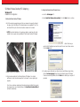
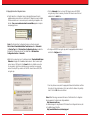
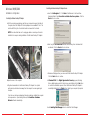
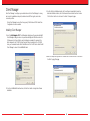
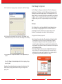
®
54Mbps Wireless Desktop PCI Adapter-g
User Manual
WLI-PCI-G54
®
4030 W. Braker Ln. Suite 120
Austin,Texas 78759
Tel: 800-456-9799
Fax: 512-794-8606
Technical Support is available 24 hours a day, 7 days a week,
Toll-Free: 866-752-6210
email: [email protected]
WWW.BUFFALOTECH.COM/WIRELESS
54 Mbps Wireless Desktop PCI Adapter-g
2. Installing the Wireless Desktop PCI Adapter Drivers:
Windows XP
Installation & Configuration
a. Insert the AirNavigator CD.
1. Installing the Wireless Desktop PCI Adapter:
b. Select Install the Software Automatically. Click the Next button to continue.
a.With the computer powered down and the cover removed to expose the inside of
the system, insert the 54Mbps PCI Desktop Adapter into an available PCI slot. The
card should fit firmly into the slot and should be screwed into the chassis.
NOTE: Care should be taken not to unplug any cables or unseat any other cards
installed in the computer during installation of the Wireless Desktop PCI Adapter.
.
c. Select the driver you
want to install. If multiple drivers are listed, select the most recent driver version.
Click the Next button.
Replace the cover of the computer.
b. Plug the antenna cable into the Wireless Desktop PCI Adapter. For optimal
performance, locate the antenna away from the computer to ensure good signal
reception.
d. If a window opens, stating that your driver does not pass Windows Logo testing,
click the Continue Anyway button.When the Wireless Desktop PCI Adapter
Drivers are successfully installed, click the Finish button. Restart your computer if
prompted.
Once the cover has been replaced and the antenna has been installed, the computer
can be powered on. Upon loading Windows, the Found New Hardware Wizard
will launch automatically.
1
2
3. Configuring Wireless Zero Configuration Service:
a. If the Wireless Zero Configuration Service is activated,Windows will scan for
available wireless access points once the Wireless PCI Adapter is properly installed.
If Windows detects one or more access points, a networking icon appears on the
task bar. One or more wireless networks are available appears as a caption
accompanying the icon.
Note: If the Wireless Zero Configuration Service is not functioning, select
Start>Control Panel>Administrative Tools>Services. Select Automatic in
the Startup Type field of Wireless Zero Configuration Service to enable the
Wireless Zero Configuration Service.The default value of Wireless Zero
Configuration Service is Automatic.
c. Click the Advanced button to enter an SSID network name or WEP/WPA
encryption key, if either is necessary. To add an SSID network name that is not
available, click the Add button.
e.To configure a WEP/WPA encryption key, select the appropriate wireless network
and click the Configure button.
b. Right click the networking icon in the taskbar, and select View Available Wireless
Networks to display a list of available wireless networks. Select an access point
network name or SSID and click the Connect button to establish a connection.
You may need to check the box indicating you are connecting to an unsecured
network. See step C if you need to enter an SSID network name or WEP/WPA
encryption key.
f. From the pull down menu, select the appropriate Network Authentication and Data
Encryption for the wireless network. Enter and confirm the Network Key and Key
Index. Click the OK button when finished.
Note: Buffalo Technology recommends that users of the Wireless Zero Configuration
Service upgrade to the latest version freely available at:
http://www.microsoft.com.
For advanced support in using Window’s XP’s Wireless Zero Configuration Service, refer
to the Buffalo Support Web Site:
http://www.buffalotech.com/wireless/support
3
4
Windows 98/ME/2000
2. Installing the Wireless Desktop PCI Adapter Drivers:
Installation & Configuration
1. Installing the Wireless Desktop PCI Adapter:
a. Insert the AirNavigator CD. Click Next at the Welcome to the Found New
Hardware Wizard. Select Search for a suitable driver for my device. Click the
Next button to continue.
a.With the computer powered down and the cover removed to expose the inside of
the system, insert the 54Mbps PCI Desktop Adapter into an available PCI slot. The
card should fit firmly into the slot and should be screwed into the chassis.
NOTE: Care should be taken not to unplug any cables or unseat any other cards
installed in the computer during installation of the Wireless Desktop PCI Adapter
b. Select only the CD-ROM drives checkbox, and clear any other checkboxes that
are selected. Click the Next button to continue.
c.Windows will display a driver you can use with the Wireless Desktop PCI Adapter.
Click the Next button to continue.
Replace the cover of the computer.
b. Plug the antenna cable into the Wireless Desktop PCI Adapter. For optimal
performance, locate the antenna away from the computer to ensure good signal
reception.
d. Windows 2000: If the Digital Signature Not Found page opens, informing
that no digital signature exists for the driver you are installing, click the Yes button
to continue the installation process. When the Wireless Desktop PCI Adapter is
successfully installed, click the Finish button. Restart your computer if prompted.
Once the cover has been replaced and the antenna has been installed, the computer
can be powered on. Upon loading Windows, the Found New Hardware
Wizard will launch automatically.
See the Installing Client Manager section to install the Client Manager.
5
6
Client Manager
Use Client Manager to configure your wireless network. Use Client Manager to survey
and connect to available access points, enable and use WEP encryption, and create
connection profiles.
3. Confirm that the installation location for the software is acceptable.To select an
alternate installation location, click the Browse button and select another location.
Click the Next button to continue to the Select Components page.
Note: Client Manager does not function properly if the Windows XP Wireless Zero
Configuration Service is enabled.
Installing Client Manager
1. Insert the AirNavigator CD. The AirNavigator dialog box will open automatically. If
the AirNavigator dialog box does not open automatically, select Start»Run and enter
D:\Setup.exe in the Open field to open the dialog box manually. D: represents the
letter assigned to the CD-ROM drive. If another letter is assigned to the CD-ROM
drive, your command should reflect that difference. Click the OK button. Select Install
Client Manager to launch the InstallShieldWizard.
4. Select the components you want to install and click the Next button to continue to
the Start Copying Files page.
2. Once the InstallShield Wizard launches, click the Next button to begin the software
installation.
7
8
5. Click the Next button to begin copying the necessary files to install Client Manager.
Client Manager Configuration
Use Client Manager to configure your wireless network.To assist in configuring your
wireless network, Client Manager consists of the Status page, the Survey page, and the
Profiles page.You can access each page by clicking the corresponding button on Client
Manager. In addition to these pages, several dialog boxes are available to meet specialized
configuration needs.You can access the Edit Profile dialog box, New Profile dialog box, IP
Configuration dialog box, or WEP Configuration dialog box using the Client Manager
pages.
Status Page
Click the Status button to open this page. By default, this page is displayed when you
start Client Manager.This page displays the status of the connection between the
wireless adapter and another wireless device.This page only displays connection
information if the wireless adapter is connected to another wireless device.
6.Click the Yes button, when prompted, to add a shortcut for Client Manager to your
Windows Startup menu. If you click the Yes button, Client Manager will run at startup.
7.Click the Finish button to complete the installation of Client Manager. Restart your
notebook.
This page includes the following components:
• Status—Displays the association status of the wireless network. Displays Associated if
the wireless adapter is connected to another wireless device and can pass data
through that device. Displays Not Associated if the wireless adapter is either not
connected to another wireless device or is connected to another wireless device but
cannot pass data through the device. If Status is Not Associated, the other components
will not display any information.
• Network Type—Displays the mode of your network. Displays Infrastructure if your
network consists of both wired and wireless devices that communicate through a
central device, such as an access point. Displays Ad-hoc if your network consists of
only wireless devices that communicate with each other directly.
Note: Client Manager and the wireless adapters will not function properly until you
reboot the system.
Depending on the operating system, some screens may vary from those shown in this
manual. However, by accepting default installation settings, Client Manager should
properly install.
9
10
• Transfer Rate—Displays the data transfer rate, the rate at which you can transmit and
receive data across the wireless network, in Mbps.The data transfer rate can be up to
54 Mbps. A variety of factors, including distance from the router, the allowable data
transfer rates of other devices, and the physical conditions of the wireless
environment, can affect the data transfer rate.
• SSID—Displays the SSID of your network.The SSID is the unique network name that
functions as an identifier for your wireless devices. All wireless devices on a network
must use identical SSIDs to successfully associate with other devices on the network.
myssid is an example of a valid SSID.
• Channel—Displays the channel your network is using.The channel indicates what range
of frequencies the radio waves are occupying. Devices that meet 802.11b and 802.11g
standards can use channels 1-11 within the 2.4 GHz spectrum.
• WEP—Displays whether WEP encryption is Enabled or Disabled.WEP encryption is a
security method for wireless communications. If WEP is Enabled, a shared encryption
key, also known as a WEP key, is necessary to access the network.
• MAC Address—Displays the MAC address of your network device. A MAC address is a
unique network name for each device on a network. 00:11:22:33:44:55 is an example
of a valid MAC address.
• Signal Strength—Displays the strength of the signal. Signal Strength is based on the peak
signal level the wireless adapter receives from the wireless device to which it is
connected.
• Signal Quality—Displays the quality of the signal. Signal Quality is a signal-to-noise ratio,
which is a measurement comparing strength of the signal with the background noise
on the wireless network.
• Channel—Displays the channel associated with each available access point.The channel
indicates what range of frequencies the radio waves emitted by the wireless device
are occupying. Devices that meet 802.11b and 802.11g standards can use channels 111 within the 2.4 GHz spectrum.
• WEP—Displays whether WEP encryption is enabled on each available access point.
Displays Yes if encryption is enabled and No if encryption is not enabled. If WEP
encryption is enabled, a shared encryption key, also known as a WEP key, is necessary
to access the network.
• Mode—Displays the transfer mode associated with each available access point. Mode
can be 11a, 11b, or 11g.
• Connect—Select an available access point and click the Connect button to connect to
that access point. If No is displayed in the WEP field and you click the Connect button,
the wireless adapter will connect to the selected access point and the Status page will
reopen. If Yes is displayed in the WEP field and you click the Connect button, the WEP
Configuration dialog box will open.
• Refresh—Click the Refresh button to update the screen.
• Signal Strength—Displays the strength of the signal. Signal Strength is based on the peak
signal level the wireless adapter receives from the wireless device to which it is
connected.
• Signal Quality—Displays the quality of the signal. Signal Quality is a signal-to-noise ratio,
which is a measurement comparing the strength of the signal with the background
noise on the wireless network.
Survey Page
Click the Survey button to open this page. Use this page to survey the area, display
available access points, and connect to available access points.
This page includes the following components:
• SSID—Displays the SSID associated with each available access point.The SSID is the
unique network name that functions as an identifier for your wireless devices. All
wireless devices on a network must use identical SSIDs to successfully associate with
other devices on the network. myssid is an example of a valid SSID.
11
12
Profiles Page
Click the Profiles button to open this page. Use this page to access your profiles. Profiles
allow you to save the information associated with a specific location so you can quickly
and easily connect to your network when you are in that location.The Profiles page
allows you to add, delete, and edit your profiles, as well as import and export data.
This page includes the following components:
• Profiles—Displays the name associated with the profile.
• SSID—Displays the SSID associated with the profile.The SSID is the unique network
name that functions as an identifier for your wireless devices. All wireless devices on a
network must use identical SSIDs to successfully associate with other devices on the
network. myssid is an example of a valid SSID.
• Network Type—Displays the network mode associated with the profile. Displays
Infrastructure if your network consists of both wired and wireless devices that
communicate through a central device, such as an access point. Displays Ad-hoc if your
network consists of only wireless devices that communicate with each other directly.
• WEP—Displays whether WEP encryption is enabled. Displays Yes if WEP encryption is
enabled and No if WEP encryption is disabled. If WEP encryption is enabled, a shared
encryption key, also known as a WEP key, is necessary to access the network.
• Connect—Click the Connect button to update your specifications and return to the
Status page.
• Add—Click the Add button to open the New Profile dialog box and add a new profile.
• Edit—Click the Edit button to open the Edit Profile dialog box and edit an existing
profile.
• Delete—Click the Delete button to delete a profile.
• Import—Click the Import button to import data.
• Export—Click the Export button to export data.
• Signal Strength—Displays the strength of the signal. Signal Strength is based on the peak
signal level the wireless adapter receives from the wireless device to which it is
connected.
• Signal Quality—Displays the quality of the signal. Signal Quality is a signal-to-noise ratio,
which is a measurement comparing the strength of the signal with the background
noise on the wireless network.
13
New Profile Dialog Box
Use this dialog box to create a new profile.
This page includes the following components:
• Profile Name—Enter the name you want to associate with the new profile.
• Network Type—Select the network mode you want to associate with the new profile.
Select Infrastructure if your network consists of both wired and wireless devices that
communicate through a central device, such as an access point. Select Ad-hoc if your
network consists of only wireless devices that communicate with each other directly.
• SSID—Enter the SSID of your network.The SSID is the unique network name that
functions an identifier for your wireless devices. All wireless devices on a network
must use identical SSIDs to successfully associate with other devices on the network.
myssid is an example of a valid SSID.
• Channel—Displays the channel associated with the new profile.The channel indicates
what range of frequencies the radio waves emitted by the wireless device are
occupying. Devices that meet 802.11b and 802.11g standards can use channels 1-11
within the 2.4 GHz spectrum.
• IP—Select your preferred method of obtaining your IP address. Select Automatically to
obtain your IP address automatically. Select Manually to manually enter your IP address.
If you select Manually the IP Configuration dialog box will open when you click the
Okay button.
14
• WEP—Select whether you want to enable WEP encryption. Select Yes to enable WEP
encryption. Select No to disable WEP encryption. If you select Yes the WEP
Configuration dialog box will open when you click the Okay button.
• OK—Click the OK button to save your specifications and return to the Profiles page.
• Cancel—Click the Cancel button to return to the Profiles page without saving your
specifications.
• Signal Strength—Displays the strength of the signal. Signal Strength is based on the peak
signal level the wireless adapter receives from the wireless device to which it is
connected.
• IP—Displays the current method of obtaining your IP address. Select Automatically or
Manually from the menu to change the method affiliated with the profile. Select
Automatically to obtain your IP address automatically. Select Manually to manually
enter your IP address. If you select Manually from the IP menu, the IP Configuration
dialog box will open when you click the Okay button.
• WEP—Displays whether WEP encryption is currently used by the profile you are
editing. Select Yes or No from the menu to change whether WEP encryption is used
with the profile. Select Yes to enable WEP encryption. Select No to disable WEP
encryption. If you select Yes from the WEP menu, the WEP Configuration dialog box
will open when you click the Okay button.
• Okay—Click the Okay button to save your changes and return to the Profiles page.
• Signal Quality—Displays the quality of the signal. Signal Quality is a signal-to-noise ratio,
which is a measurement comparing strength of the signal with the background noise
on the wireless network.
Edit Profile Dialog Box
Select Profiles»Edit to open this dialog box. Use this dialog box to edit the settings of an
existing profile.
• Cancel—Click the Cancel button to return to the Profiles page without saving your
changes.
• Signal Strength—Displays the strength of the signal. Signal Strength is based on the peak
signal level the wireless adapter receives from the wireless device to which it is
connected.
This page includes the following components:
• Signal Quality—Displays the quality of the signal. Signal Quality is a signal-to-noise ratio,
which is a measurement comparing strength of the signal with the background noise
on the wireless network.
• Profile Name—Displays the current name of the profile you are editing. Enter any
changes to the name of the profile in this field.
IP Configuration Dialog Box
• Network Type—Displays the current network mode of the profile you are editing.
Select Infrastructure or Ad-hoc from the menu to change the network type of the
profile. Select Infrastructure if your network consists of both wired and wireless
devices that communicate through a central device, such as an access point. Select Adhoc if your network consists of only wireless devices that communicate with each
other directly.
Use this dialog box to manually set your Internet Protocol (IP) specifications.
This page includes the following components:
• IP Address—Enter the IP address of your network.
• Subnet Mask—Enter the subnet mask.
• SSID—Displays the current SSID of the profile you are editing. Enter any changes to
your SSID in this field.The SSID is the unique network name that functions as an
identifier for your wireless devices. All wireless devices on a network must use
identical SSIDs to successfully associate with other devices on the network. myssid is
an example of a valid SSID.
15
• Okay—Click the Okay button to save your specifications and return to the previous
dialog box, either the New Profile dialog box or the Edit Profile dialog box.
16
• Cancel—Click the Cancel button to return to the previous dialog box, either the New
Profile dialog box or the Edit Profile dialog box, without saving your specifications.
• Signal Strength—Displays the strength of the signal. Signal Strength is based on the peak
signal level the wireless adapter receives from the wireless device to which it is
connected.
• Signal Quality—Displays the quality of the signal. Signal Quality is a signal-to-noise ratio,
which is a measurement comparing strength of the signal with the background noise
on the wireless network.
WEP Configuration Dialog Box
WEP Key—Enter your WEP key.Your WEP key is the shared encryption key that is
required before a device can access your network.The following table displays the
appropriate length of the WEP key, which is based on the WEP Type and Key Format
values.
WEP Type Key Format WEP Key
64-bit encryption ASCII 5 characters
64-bit encryption Hex 10 characters
128-bit encryption ASCII 13 characters
128-bit encryption Hex 26 characters
This page includes the following components:
Okay—Click the Okay button to save your settings and return to the previous page.
Cancel—Click the Cancel button to cancel your action.
• Signal Strength—Displays the strength of the signal. Signal Strength is based on the peak
signal level the wireless adapter receives from the wireless device to which it is
connected.
WEP Type—Select the WEP encryption format, 64-bit encryption or 128-bit encryption,
from the menu.You must use the same WEP encryption format for all devices on your
wireless network.
• Signal Quality—Displays the quality of the signal. Signal Quality is a signal-to-noise ratio,
which is a measurement comparing strength of the signal with the background noise
on the wireless network.
Use this dialog box to configure the settings for WEP encryption.
Note: Some wireless products offer only 64-bit WEP encryption. If any products on
your network offer only 64-bit WEP encryption,WEP Type must be 64-bit
encryption.
Key Format—Select the format for the WEP key, ASCII or Hex, from the menu. Select
ASCII if you want to use alphanumeric characters. Select Hex if you want to use
hexadecimal characters.You must use the same WEP key format for all devices on your
wireless network.
Note: Hexadecimal is a more common WEP key format than ASCII. If your network
contains products from different vendors, select Hex to ensure WEP key
compatibility.
17
18
Wireless Zero Configuration Service
(Windows XP)
Windows XP offers the Wireless Zero Configuration Service to support 802.11b and
802.11g wireless networking.This service automatically polls the area for available
wireless access points. If an available wireless access point is found,Windows attempts to
connect to the access point. If no available wireless access points are found, you must
manually add the access points.
Note:The Wireless Zero Configuration Service and Client Manager do not function
properly together. If you want to use Client Manager, you must disable the Wireless Zero
Configuration Service.
Enabling the Wireless Zero Configuration Service
Select Start»Control Panel»Administrative Tools»Services to open the Services window.
Select Automatic in the Startup Type field of Wireless Zero Configuration Service to
enable the Wireless Zero Configuration Service.
Note:The default Startup Type value of Wireless Zero Configuration Service is
Automatic.
Disabling the Wireless Zero Configuration Service
Select Start»Control Panel»Administrative Tools»Services to open the Services window.
Select Disabled in the Startup Type field of Wireless Zero Configuration Service to
disable the Wireless Zero Configuration Service.
19
Specifications
Receiver Sensitivity -69dBm, -72dBm, -77dBm, 81dBm, -85dBm, -88dBm -87dBm -90 dBm -92
dBm (depends on data rate)
Delay Spread (at FER of <1%) 65 ns 225 ns 400 ns
500 ns (depends on data rate)
• The range of wireless devices can be affected by
metal surfaces, solid high-density materials and
obstacles in the signal path.
• In Open Office environments, clients can “see”
each other, i.e. there are no physical obstructions
between them.
• In Semi-open Office environments, work space is
separated by room dividers; client cards are at
desktop level.
• In Closed Office environments, workspace is
separated by floor-to-ceiling brick walls.
NOTE: The range values listed in Table “Radio
Characteristics” are typical distances as measured
at Buffalo Technology AirStation laboratories.These
values are provided for your guidance but may vary
according to the actual radio conditions at the
location where the AirStation product is installed.
AirStation IEEE 802.11 Channel Sets
The range of the wireless signal is related to the
Transmit Rate of the wireless communication.
Communications at a lower Transmit range may
travel longer distances.
Center Channel ID FCC
1 2412
2 2417
3 2422
4 2427
5 2432
6 2437
7 2442
8 2447
9 2452
10 2457
11 2462 1
1 default channel
Regulatory Information A
Wireless communication is often subject to local
radio regulations. Although AirStation wireless
networking products have been designed for
operation in the license-free 2.4 GHz band, local
radio regulations may impose limitations on the use
of wireless communication equipment.
Networking Characteristics Compatibility
• IEEE 802.11g Standard for Wireless LANs (DSSS)
• Wi-Fi (Wireless Fidelity) certified by the Wi-Fi
Alliance.
Host Operating System
Microsoft Windows(r) ME/98/NT4.0/2000/XP
Media Access Protocol
CSMA/CA (Collision Avoidance) with
Acknowledgment (ACK)
Radio Characteristics (Typical Indoor Ranges)
R-F Frequency Band 2.4 GHz (2400-2483 MHz)
11 selectable sub-channels
Modulation Technique Direct Sequence Spread
Spectrum
• ODFM for High Transmit Rate
• CCK for Medium Transmit Rate
• DQPSK for Standard Transmit Rate
• DBPSK for Low Transmit Rate
Spreading 11-chip Barker Sequence
Bit Error Rate (BER) Better than 10 -5
Nominal Output Power 15 dBm (32mW)
Transmit Rate / Range
High Speed 54Mbps
Standard Speed 20 Mbps
Low Speed 1 Mbps
Open Office Environment
160 m (525 ft.)
270 m (885 ft.)
400 m (1300 ft.)
550 m (1750 ft.)
Semi-Open Office Environment
50 m (165 ft.)
70 m (230 ft.)
90 m (300 ft.)
115 m (375 ft.)
Closed Office
25 m (80 ft.)
35 m (115 ft.)
40 m (130 ft.)
50 m (165 ft.)
External Antenna Connector
MC Card
20
Troubleshooting/FAQ
Glossary
Use this section to locate answers to frequently asked questions.
802.11b—Standards set by IEEE for wireless networking hardware. 802.11 standards
specify how wireless devices can interact with an access point or another wireless
device.WLANs that meet 802.11b standards can transmit at speeds of 1, 2, 5.5, or 11
Mbps in a 2.4 GHz band. All products that adhere to these standards are compatible with
each other, regardless of brand.
802.11g—New proposed standards for wireless networking hardware. 802.11 standards
specify how wireless devices can interact with an access point or another wireless
device.WLANs that meet 802.11g standards can transmit at speeds up to 54 Mbps in a
2.4 GHz band. All products that adhere to these standards are compatible with each
other, regardless of brand.
Access Point—An access point (AP) is a hardware device or a computer's software that
acts as a communication hub. APs enable wireless devices to connect to wired LANs. APs
provide heightened wireless security and extend the physical range of service a wireless
user can access.
Ad-hoc Mode—Networks that function in ad-hoc mode consist of devices that
communicate with each other directly, without using an access point. Each device must
have a wireless adapter so it can connect as an independent WLAN. Ad-hoc mode is also
called peer-to-peer mode or an Independent Basis Service Set (IBSS). Networks that
function in ad-hoc mode are most useful when no wireless infrastructure previously
exists or external services are not required.
BSS—A Basic Service Set (BSS) consists of a wired network and wireless devices that
use an access point to connect to each other.
Channel—A channel is a communications path between two computers or devices.
Digital Signature—A digital signature is an encrypted code that uniquely identifes the
sender of electronically transmitted data. A digital signature functions as a security device
by authenticating the identity of the person sending the data.
DNS—The domain name system (DNS) translates domain names, also known as URLs,
into IP addresses. DNS servers create and maintain these associations.There should be
one or more DNS servers within close geographical proximity of your access provider.
ESS—An Extended Service Set (ESS) consists of two or more Basic Service Sets that
form a single subnetwork.
IBSS—See Ad-hoc Mode.
IEEE—The Institute of Electrical Engineers (IEEE) develops standards for the computer
and electronics industry.The IEEE is currently finalizing the draft standards for 802.11g
technology.
What should I do if I already have a version of Client Manager on my notebook?
Update your Client Manager to the version on the CD. If you do not update your Client
Manager, there could be a loss of functionality, as some versions of Client Manager will
not work properly with the G54 Wireless Notebook Adapter.To update your Client
Manager, load the Air Navigator CD and select Install Client Manager. If an old version of
Client Manager is on your notebook, the InstallShield Wizard prompts you to select
Remove, Repair, or Cancel Operation. Select Repair to update your Client Manager to
the version on the CD.
Why won't all my network clients work?
Some operating systems support only a limited number of network clients.
Windows 98/Me:These operating systems support only four network clients. If you
install more than four network clients, only the first four clients you install will work.
Will Client Manager support all operating systems?
Client Manager and the G54 Wireless Notebook Adapter currently support only
Windows 98/ME/2000/XP.They do not currently support Windows NT, Mac OS, or
Linux. For more information, refer to the Mac OS and Linux page in the Troubleshooting
section of this help file.
Where can I attach my external antenna?
Insert your external antenna into the antenna slot, located on the back of the G54
Wireless PCI Adapter.
Why won't Client Manager function properly?
Windows XP—The Wireless Zero Configuration Service conflicts with Client Manager.
Select Start»Control Panel»Administrative Tools»Services to open the Services window.
Select Disabled in the Startup Type field of Wireless Zero Configuration Service to
disable the Wireless Zero Configuration Service.
I have more than one Air Navigator CD. Do I need more than one CD?
No.You receive the same Air Navagator CD with each Buffalo Technology access point
and wireless adapter.The CDs are identical and you only need one copy.
21
22
Infrastructure Mode—Networks that function in infrastructure mode consist of devices
that communicate with each other through an access point.Wireless devices can
communicate with wired networks or other wireless devices by going through an access
point. Infrastructure mode is also called a Basic Service Set (BSS), if it consists of wireless
devices and a wired network. Networks that function in infrastructure mode are most
useful when a WLAN requires access to a wired LAN for services such as file sharing
and printing.
IP Address—An Internet Protocol (IP) address is an identifier for a device or computer
on a TCP/IP network. An IP address is a 32-bit numeric address written as four numbers
separated by decimal points. 0 to 255 is the available range for each number.
1.225.37.123 is an example of a valid IP address.
LAN—A local-area network (LAN) is a computer network that spans a relatively small
area, such as one building or a small group of buildings. Each node in a LAN can access
data and devices anywhere on the LAN. However, each node must have a separate CPU
to execute programs.
MAC Address—A Media Access Control (MAC) address is an identifier for each node of
a network. MAC addresses are unique hardware numbers assigned to each computer or
device. A MAC address consists of twelve numbers written as six pairs separated by
colons or dashes. 11:22:33:44:55:66 is an example of a valid MAC address.
Node—A node is any device or computer on a network.
SSID—A Service Set Identifier (SSID) is an alphanumeric identifier that acts as a
password for devices on a WLAN. SSIDs are case-sensitive and consist of a minimum of
two characters and a maximum of 32 characters. SSIDs can function as rudimentary
security and can also be used for network segmenting. SSIDs differentiate between
WLANs, so all access points and devices attempting to connect to a specific WLAN must
use identical SSIDs. myssid is an example of a valid SSID.
TCP/IP—Transmission Control Protocol/Internet Protocol (TCP/IP) is a collection of
communications protocols for connecting hosts to the Internet.TCP/IP is the industry
standard for transmitting data over networks.
WEP—Wired Equivalent Privacy (WEP) is a security measure available for WLANs to
help them be as secure as wired LANs.WEP provides security by encrypting data so it is
protected as it is transmitted over radio waves.To read encrypted files you must have
access to the password, or key, that decrypts the files.
23
WEP key—A WEP key is a decryption key, or password, that is required to access any
WEP-encrypted data.To effectively enable WEP encryption, you must enter your WEP
key.
Wi-Fi—Wireless Fidelity (Wi-Fi) refers to any wireless networking equipment that
adheres to 802.11 standards.
Wireless Notebook Adapter—A wireless notebook adapter is a 32-bit wireless
connection device that fits in the PC card slot of a notebook computer.
Wireless Zero Configuration Service—Windows XP offers the Wireless Zero
Configuration Service to support 802.11b and 802.11g wireless networking.This service
automatically polls the area for available wireless access points. If an available wireless
access point is found,Windows attempts to connect to the access point. If no available
wireless access points are found, you must manually add the access points.
WLAN—A wireless local-area network (WLAN) is a local-area network that uses highfrequency radio waves to communicate between nodes.
24
FCC/CE
Federal Communication Commission Interference Statement
This equipment has been tested and found to comply with the limits for a Class B digital
device, pursuant to Part 15 of the FCC Rules.These limits are designed to provide
reasonable protection against harmful interference in a residential installation.This
equipment generates, uses and can radiate radio frequency energy and, if not installed
and used in accordance with the instructions, may cause harmful interference to radio
communications. However, there is no guarantee that interference will not occur in a
particular installation. If this equipment does cause harmful interference to radio or
television reception, which can be determined by turning the equipment off and on, the
user is encouraged to try to correct the interference by one of the following measures:
- Reorient or relocate the receiving antenna.
- Increase the separation between the equipment and receiver.
- Connect the equipment into an outlet on a circuit different from that to which the
receiver is connected.
- Consult the dealer or an experienced radio/TV technician for help.
FCC Caution:To assure continued compliance, (example - use only shielded interface
cables when connecting to computer or peripheral devices). Any changes or
modifications not expressly approved by the party responsible for compliance could void
the user's authority to operate this equipment.
This device complies with Part 15 of the FCC Rules. Operation is subject to the
following two conditions: (1) This device may not cause harmful interference, and (2) this
device must accept any interference received, including interference that may cause
undesired operation.
IMPORTANT NOTE:
FCC RF Radiation Exposure Statement:
This equipment complies with FCC RF radiation exposure limits set forth for an
uncontrolled environment.This equipment should be installed and operated with a
minimum distance of 20 centimeters between the radiator and your body.
This transmitter must not be co-located or operating in conjunction with any other
antenna or transmitter.
R&TTE Compliance Statement
This equipment complies with all the requirements of the DIRECTIVE 1999/5/EC OF
THE EUROPEAN PARLIAMENT AND THE COUNCIL of 9 March 1999 on radio
equipment and telecommunication terminal Equipment and the mutual recognition of
their conformity (R&TTE).The R&TTE Directive repeals and replaces in the directive
98/13/EEC (Telecommunications Terminal Equipment and Satellite Earth Station
Equipment) As of April 8, 2000.
25
Safety
This equipment is designed with the utmost care for the safety of those who install and
use it. However, special attention must be paid to the dangers of electric shock and static
electricity when working with electrical equipment. All guidelines of this manual and of
the computer manufacturer must therefore be allowed at all times to ensure the safe use
of the equipment.
EU Countries intended for use
The ETSI version of this device is intended for home and office use in Austria, Belgium,
Denmark, Finland, France (with Frequency channel restrictions), Germany, Greece,
Iceland, Ireland, Italy, Luxembourg, Norway,The Netherlands, Portugal, Spain, Sweden,
Switzerland and United Kingdom.
The ETSI version of this device is also authorized for use in EFTA member states Iceland,
Liechtenstein, Norway and Switzerland.
EU Countries Not intended for use
None.
Potential restrictive use
France: Only channels 10,11,12, and13
Technical Support
Buffalo Technology offers toll-free technical support 24 hours a day, 7 days a week for
this product. Customers in the United States and Canada can obtain technical support
using the following information:
Online Help—Available on the AirNavigator CD enclosed with your purchase.
Website—www.buffalotech.com/wireless
E-mail—[email protected]
Telephone—866.752.6210
The constantly evolving state of wireless products and operating systems requires Buffalo
Technology to occasionally release updated software to take advantage of new
technologies and to comply with industry standards. For the most recent software,
firmware, driver, and technical whitepaper releases available, please visit the Buffalo
Technology website.
26