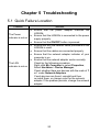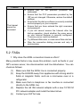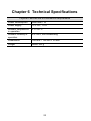
1
EchoLife HG520b Home Gateway
User Manual
HUAWEI TECHNOLOGIES CO., LTD.
EchoLife HG520b Home Gateway User Manual
Issue
02
Date
2008-06-28
Part Nubmer
202072
Huawei Technologies Co., Ltd.
Address:
Huawei Industrial Base
Bantian, Longgang
Shenzhen 518129
People's Republic of China
Website:
http://www.huawei.com
Email:
[email protected]
Copyright © Huawei Technologies Co., Ltd. 2008. All rights reserved.
No part of this document may be reproduced or transmitted in any form or by
any means without prior written consent of Huawei Technologies Co., Ltd.
Trademarks and Permissions
and other Huawei trademarks are trademarks of Huawei Technologies
Co., Ltd.
All other trademarks and trade names mentioned in this document are the
property of their respective holders.
Notice
The information in this document is subject to change without notice. Every
effort has been made in the preparation of this document to ensure accuracy
of the contents, but all statements, information, and recommendations in this
document do not constitute the warranty of any kind, express or implied.
This product has been designed to comply with the requirements on
environmental protection. For the proper storage, use and disposal of this
product, national laws and regulations must be observed.
Federal Communications Commission (FCC)
Interference Statement
This equipment has been tested and found to comply with the limits for a Class
B digital device, pursuant to Part 15 of the FCC Rules. These limits are
designed to provide reasonable protection against harmful interference in a
residential installation.
This equipment generates, uses and can radiate radio frequency energy and if
not installed and used in accordance with the instructions, may cause harmful
interference to radio communications. However, there is no guarantee that
interference will not occur in a particular installation. If this equipment does
cause harmful interference to radio or television reception, which can be
determined by turning the equipment off and on. The user is encouraged to try
to correct the interference by one of the following measures:
Reorient or relocate the receiving antenna.
Increase the separation between the equipment and receiver.
Connect the equipment into an outlet on a circuit different from that to
which the receiver is connected.
Consult the dealer or an experienced radio/TV technician for help.
To assure continued compliance, any changes or modifications not expressly
approved by the party responsible for compliance could void the user’s
authority to operate this equipment. (Example- use only shielded interface
cables when connecting to computer or peripheral devices).
FCC Radiation Exposure Statement
This equipment complies with Part 15 of the FCC Rules. Operation is subject
to the following two conditions:
(1) This device may not cause harmful interference, and
(2) This device must accept any interference received, including interference
that may cause undesired operation.
This equipment has been tested and found to comply with the limits for a Class
B digital Device, pursuant to Part 15 of the FCC rules.
Safety Precaution
The antenna(s) used for this transmitter must be installed to provide a
separation distance of at least 20cm from all persons.
Channel
This equipment marketed in USA is restricted by firmware to only operate on
2412~2462MHz channel 01~11.
Safety Precautions
For safety purposes, carefully read through these safety precautions and
observe them during operation.
z
z
z
z
z
z
z
z
z
z
z
z
z
z
Basic requirements
Keep the device dry during storage, transportation, and operation of
the device.
Prevent collision of the device with other objects during storage,
transportation, and operation of the device.
Do not attempt to dismantle the device. In case of any fault, contact
the authorized maintenance center for assistance or repair.
Without prior written consent, no organization or individual is
permitted to make any change to the structure, safety, and
performance design of the device.
While using the device, observe all applicable laws, directives and
regulations, and respect the legal rights of other people.
Environmental Requirements
Place the device in a well-ventilated place. Do not expose the
device to direct sunlight.
Keep the device clean, free of dust and stain.
Do not place the device near a water source or in a damp area.
Place the device on a stable surface.
Do not place any object on the top of the device. Reserve a
minimum space of 10 cm at the four sides and on the top of the
device for heat dissipation.
Do not place the device on or near inflammable materials such as
foam.
Keep the device away from heat source or fire, such as a radiator or
a candle.
Keep the device away from any household appliances with strong
magnetic field or electric field, such as microwave oven, refrigerator,
or mobile phone.
Operation Requirements
Do not allow children to play with the device or accessories.
Swallowing the accessories may be fatal.
z
z
z
z
z
z
z
z
z
z
z
z
z
z
Use the accessories such as the power adaptor provided or
authorized only by the manufacturer.
Make sure that the device does not get wet. If water gets into the
device, disconnect the power supply immediately and unplug all the
cables connected to the device, such as the power cable, and then
contact the authorized maintenance center.
The power supply of the device must meet the requirements of the
input voltage of the device.
Before plugging or unplugging any cable, shut down the device and
disconnect the power supply.
While plugging or unplugging any cable, make sure that your hands
are dry.
Do not step on, pull, or stretch any cable. Otherwise, the cable may
get damaged, leading to malfunction of the device.
Do not use old or damaged cables.
Keep the power plug clean and dry, to prevent electric shock or
other dangers.
During lightning, disconnect the device from the power supply, and
unplug all the cables connected to the device, such as the power
cable, telephone cable, to avoid lightning strike.
If the device is not used for a long time, disconnect the power supply
and unplug the power plug.
If smoke, sound, or smell is emitted from the device, stop using the
device immediately, disconnect the power supply, unplug the power
supply and other cables. Contact the authorized maintenance
center for repair.
Make sure that no object (such as metal shavings) enters the device
through the heat dissipation vent.
Do not scratch or abrade the shell of the device. The shed painting
may lead to skin allergy or malfunctions of the device. If the shed
painting material drops into the host, a short circuit may occur.
Cleaning Requirements
Before cleaning the device, stop using it, disconnect the power
supply, and unplug all the cables connected to the device, such as
the power cable, and telephone cable.
z
z
z
z
z
z
z
z
Do not clean the device cover with any cleaning solution or cleanser
spray. Use a piece of soft cloth to clean the device cover.
Wireless Product Usage Requirements
Keep the device away from magnetic storage devices (e.g., a
magnetic card or a floppy disk), to prevent loss of the stored
information.
Stop using the device or disconnect the power supply in situations
where wireless device is prohibited or using of a wireless device
leads to interference or danger.
The user who uses an electronic assistant medical-treatment device
needs to confirm with the service center regarding the effects of the
radio wave on this device.
Do not take the device to the operation theater, Intensive Care Unit
(ICU) or the Coronary Care Unit (CCU).
When using the device maintain distance of 20 cm between your
body and the antenna of the device.
Do not drop, throw or try to bend your wireless device.
Do not place the wireless device and its accessories in high
temperature areas.
Environmental Protection
Do not dispose the abandoned device in a garbage can. You need to dispose it
according to the local regulations on disposing of device packing materials,
exhausted battery and abandoned device, and support the recycling activity.
Table of Contents
Chapter 1 Introduction ........................................................................1
1.1 Functions and Features.........................................................1
1.2 Hardware Configuration ........................................................1
1.2.1 Front Panel .................................................................2
1.2.2 Rear Panel..................................................................3
1.2.3 Splitter.........................................................................4
Chapter 2 Installation of the HG520b .................................................5
2.1 Preparation............................................................................5
2.2 Connecting the HG520b........................................................5
2.3 Establishing Configuration Environment ...............................6
2.3.1 Parameter Configuration.............................................6
2.3.2 Steps...........................................................................6
2.4 Web Configuration Page .......................................................7
Chapter 3 Service Configuration.........................................................8
3.1 Service Modes of the HG520b ..............................................8
3.2 Configuring the Bridge Mode ..............................................10
3.2.1 Preparation ...............................................................10
3.2.2 Steps.........................................................................10
3.3 Configuring the PPPoA Mode .............................................12
3.3.1 Preparation ...............................................................12
3.3.2 Steps.........................................................................12
3.4 Configuring the IPoA Mode .................................................13
3.4.1 Preparation ...............................................................13
3.4.2 Steps.........................................................................14
i
3.5 Configuring the RFC2684B Mode .......................................14
3.6 Configuring the PPPoE mode .............................................14
3.7 Configuring the Wireless Mode ...........................................15
3.7.1 Preparation ...............................................................15
3.7.2 Steps.........................................................................15
Chapter 4 Other Settings ..................................................................17
4.1 Changing the IP Address of the LAN of the HG520b..........17
4.2 Changing the Administrator Password................................17
4.3 Restoring the Default Factory Settings ...............................18
Chapter 5 Troubleshooting ...............................................................20
5.1 Quick Failure Location.........................................................20
5.2 FAQs ...................................................................................21
Chapter 6 Technical Specifications ..................................................23
Chapter 7 Appendix ..........................................................................24
7.1 Default Factory Settings ......................................................24
7.2 Abbreviations.......................................................................24
ii
Chapter 1 Introduction
This chapter introduces functions and structure of the EchoLife
HG520b Home Gateway (hereinafter referred to as the HG520b).
1.1 Functions and Features
The HG520b is a type of Asymmetric Digital Subscriber Line (ADSL)
terminal. Data, video and audio are transmitted through the common
telephone line at a higher rate by the HG520b.
The features of the HG520b are:
z
High transmission rate: The maximum downstream rate is
24 Mbit/s; the maximum upstream rate is 1.2 Mbit/s.
z
Strong network adaptability: The HG520b can be
interconnected with multiple Digital Subscriber Line Access
Multiplexer (DSLAMs).
z
Strong maintainability: The HG520b provides multiple
indicator status, which is convenient to locate failures.
z
Easy operation: The HG520b has a simple operation for the
configuration page.
1.2 Hardware Configuration
This section introduces the appearance and the structure of the
HG520b.
1
Note:
Figures of the front panel and the rear panel are only for your
reference.
1.2.1 Front Panel
Figure 1-1 shows the front panel of the HG520b.
POWER
WLAN
LAN1
LAN2
LAN3
LAN4
ADSL INTERNET
Figure 1-1 Front panel of the HG520b
Table 1-1 shows indicators in the front panel.
Table 1-1 Indicators in the front panel
Indicator
POWER
WLAN
LAN 1–4
Status
Description
On
The HG520b is powered on.
Off
The HG520b is powered off.
On
WLAN function is enabled.
Blinking
There are data being transmitted in the
WLAN interface.
Off
WLAN function is disabled.
On
The connection is established in the LAN
interface.
Blinking
There are data being transmitted in the
LAN interface.
Off
No connection is established in the LAN
interface.
2
Indicator
ADSL
INTERNET
Status
Description
On
The DSL connection is established.
Blinking
There are two state:
z Slow-Blinking
The telephone line is not connected or the
DSL connection is not established.
z fast-Blinking
The DSL connection is being activated.
Off
The HG520b is powered off.
On
The embedded PPPoE and PPPoA
dial-ups of the HG520b are successful, but
there is no data transmission.
Blinking
There are data being transmitted in the
INTERNET interface.
Off
The HG520b is in the bridge mode or the
PPPoE/PPPoA connection is not
established.
1.2.2 Rear Panel
Figure 1-2 shows the rear panel of the HG520b.
POWER
LAN4
LAN3
LAN2
LAN1
ADSL
Figure 1-2 Rear panel of the HG520b
Table 1-2 shows interfaces and buttons in the rear panel.
Table 1-2 Interfaces and Buttons in the rear panel
Interface/
Button
POWER
Description
To connect to the power adapter.
3
Interface/
Button
Description
LAN 1–4
Ethernet interfaces.
To connect LAN network devices (such as a computer and a
switch).
ADSL
ADSL interface.
To connect the telephone jack or a splitter through a telephone
line.
RESET
At the side of HG520b.
To restore the default settings of the HG520b, press the
RESET button and release it after six seconds. Once you use
this function, all your custom settings will be lost. Therefore,
please be careful when using it.
WLAN
At the side of HG520b.
To enable or disable wireless function quickly.
ON/OFF
At the side of HG520b.
To power on/off the HG520b.
1.2.3 Splitter
The external splitter can efficiently reduce the signal disturbance on the
telephone line. When voice and data are transmitted through the same
telephone line at the same time, you need an external splitter to
separate the voice and data signals:
z
LINE: Connecting to the phone jack on the wall.
z
PHONE: Connecting to the telephone.
z
MODEM: Connecting to the ADSL interface of the HG520b.
4
Chapter 2 Installation of the HG520b
This chapter introduces the installation when the HG520b is used for
the first time.
2.1 Preparation
Connect your computer with the HG520b through the Ethernet
interfaces. Before installing the HG520b, make sure that your computer
is equipped with the network card
2.2 Connecting the HG520b
Figure 2-1 shows the connection of the HG520b.
POWER
LAN4
LAN3
LAN2
LAN1
ADSL
5
4
3
1
2
2
2
2
6
1 Power adaptor
2 Computer
3 Switch
4 Splitter
5 Phone Jack
6 Phone
Figure 2-1 Connection of the HG520b
5
2.3 Establishing Configuration Environment
You can configure the HG520b on the Web configuration page. This
section describes the process to establish the configuration
environment of the HG520b.
2.3.1 Parameter Configuration
Before establishing the configuration environment, set the following
parameters.
Table 2-1 Parameters for the configuration environment
Name
Description
Administrator username and
password of the HG520b
Default:
z Username: admin
z Password: admin
IP address and subnet mask
of the LAN of the HG520b
Default:
z IP address: 192.168.1.1
z Subnet mask: 255.255.255.0
IP address and subnet mask
of the computer
Set them to be in the same network
segment as the IP address of the LAN of the
HG520b
For example:
z IP address: 192.168.1.100
z Subnet mask: 255.255.255.0
2.3.2 Steps
Follow the steps to establish the configuration environment.
Step
1
To...
Connect the
HG520b
Do...
For details to connect the HG520b, refer to 2.2
"Connecting the HG520b."
6
Step
2
3
To...
Do...
Make sure not
to use the proxy
server.
The process to unselect this function is described
as follows (taking Internet Explorer 6.0 as an
example):
(1) Start the Internet Explorer. Select Tools >
Internet Options... to display the Internet
Options dialog box.
(2) Select the Connections tab. Click LAN
Settings....
(3) Deselect Use a proxy server for your LAN
(These settings will not apply to dial-up
or VPN connections).
Log in to the
Web
configuration
page
(1) In the address bar of Internet Explorer, enter
http://192.168.1.1 (the default IP address of
the HG520b). Then press Enter. The login
window is displayed.
(2) Enter the username and the password of the
administrator in the login window.
When the password is authenticated, you
can access the Web configuration page.
Note:
After configuring the parameters of the HG520b, configure the
computer according to the configuration status of the HG520b. For
details, please refer to Chapter 3 "Service Configuration."
2.4 Web Configuration Page
The Web configuration page of the HG520b is divided into two parts:
z
The navigation tree: It is on the left side of the page. It
provides you to access to different configuration pages.
z
Configuration area: It is on the right side of the page.
7
Chapter 3 Service Configuration
This chapter introduces the method for configuring the HG520b.
Note:
The figures in the following configuration operations are only for your
reference.
3.1 Service Modes of the HG520b
The HG520b supports multiple service modes and the configuration of
the DSLAM at the office end should be considered when you select a
service mode. Table 3-1 lists the service modes of the HG520b.
Table 3-1 Service modes of the HG520b
Service Mode
Working Method
z
Bridge
z
z
z
PPPoA
z
Configuration
Take the HG520b as bridge
equipment.
Use the PPPoE dial-up software
of the computer for dialing.
Refer to 3.2
"Configuring
the Bridge
Mode."
Take the HG520b as a router.
Use the PPPoA dial-up software
of the HG520b for dialing.
Use the PPPoA encapsulation
mode to encapsulate the
packets.
Refer to 3.3
"Configuring
the PPPoA
Mode."
8
Service Mode
Working Method
z
z
IPoA
z
z
z
RFC2684B
z
z
z
PPPoE
z
Configuration
Take the HG520b as a router.
The HG520b uses the static
public IP address to access the
Internet.
Use the IPoA encapsulation
mode to encapsulate the
packets.
Refer to 3.4
"Configuring
the IPoA
Mode."
Take the HG520b as a router.
Use the static IP address or the
IP address dynamically allocated
by the ISP.
Use
the
IPoE/IPoA
encapsulation
mode
to
encapsulate the packets.
Refer to 3.5
"Configuring
the RFC2684B
Mode."
Take the HG520b as a router.
Use the embedded PPPoE
dial-up software of the HG520b
for dialing.
Use the PPPoE encapsulation
mode to encapsulate the
packets.
Refer to 3.6
"Configuring
the PPPoE
mode."
Note:
ISP = Internet Service Provider
IPoA = Internet Protocol over ATM
PPPoE = PPP over Ethernet
PPPoA = PPP over ATM
Caution:
Some parameters are validated only after they are saved and the
HG520b is rebooted. Follow the prompt in the configuration page to
perform this operation.
9
3.2 Configuring the Bridge Mode
In the bridge mode, the HG520b serves as a bridge. You need to install
the Point to Point Protocol (PPP) dial-up software to realize the dial-up
access to the Internet.
This section describes the process to configure the HG520b to work in
the bridge mode and the process to configure your computer to access
the Internet through the HG520b.
3.2.1 Preparation
Table 3-2 shows the configuration for the bridge mode.
Table 3-2 Configuration for the bridge mode
Name
Configuration
Mode
Bridge
VPI/VCI
Provided by the ISP
PPP dial-up software
Install the PPP dial-up software on your
computer to access the Internet (The
Windows XP operating system is provided
with the PPP dial-up software)
Username and password for
the PPPoE dial-up
Provided by the ISP
Note:
VPI = Virtual Path Identifier
VCI = Virtual Channel Identifier
3.2.2 Steps
Configure the following equipment:
z
The HG520b
z
Your computer
10
1. Configuring the HG520b
Follow the steps:
(1)
(2)
(3)
(4)
(5)
Log in to the Web configuration page of the HG520b. For the
procedure, refer to "2.3 Establishing Configuration
Environment."
Select Basic > WAN Setting in the navigation tree to
display the WAN configuration page.
In the WAN configuration page, select the PVC that needs to
be configured.
Set Mode to Bridge. Configure relevant parameters
according to the values in the Table 3-2.
Click Submit.
2. Configuring your computer
After completing the configuration of the HG520b, you need to install
the PPP dial-up software to access the Internet.
The Windows XP (Professional) operating system has a embedded
PPPoE dial-up software. To set up a dial-up connection in Windows XP
system, do as follows:
(1)
(2)
(3)
(4)
(5)
(6)
(7)
(8)
Select Start > All Programs > Accessories >
Communications > Network Connections.
Click Create a new connection in the displayed page.
Click Next in the New Connection Wizard dialog box.
Select Connect to the Internet and click Next.
Select Set up my connection manually and click Next.
Select Connect using a broadband connection that
requires a username and password and click Next.
Enter the name of the connection. You can name it as you
like. Then click Next.
Select an option from Anyone's use or My use only and
click Next.
11
(9) Enter the username and password. Then click Next.
(10) Click Finish.
3.3 Configuring the PPPoA Mode
In the PPPoA mode, the HG520b uses the embedded PPP dial-up
software for dialing. The HG520b serves as a router to connect your
computer to the Internet.
This section describes the process to configure the HG520b to work in
the PPPoA mode and the process to configure your computer to
access the Internet through the HG520b.
3.3.1 Preparation
Table 3-3 shows the configuration for the PPPoA mode.
Table 3-3 Configuration for the PPPoA mode
Name
VPI/VCI
Configuration
Provided by the ISP
Mode
Route and PPPoA
Encapsulation
PPPoA
Username and password for the
PPPoA dial-up
Provided by the ISP
3.3.2 Steps
1. Configuring the HG520b
Follow the steps described as follows:
(1)
(2)
Log in to the Web configuration page. For the procedure,
refer to "2.3 Establishing Configuration Environment."
Select Basic > WAN Setting in the navigation tree to
display the WAN configuration page.
12
(3)
(4)
(5)
(6)
(7)
In the WAN configuration page, select the PVC that needs to
be configured.
Set Mode to Routing and set Encapsulation to PPPoA.
Configure the relevant parameters according to the values in
the Table 3-3.
Fill in the username and the password (provided by the ISP).
Click Submit.
2. Configuring Your Computer
Configure the network card for your computer, to enable the computer
to automatically obtain information such as the IP address and the
gateway.
3.4 Configuring the IPoA Mode
This section describes the process to configure the HG520b in the
IPoA mode and the process to configure your computer to access the
Internet through the HG520b.
3.4.1 Preparation
Table 3-4 shows the configuration for the IPoA mode.
Table 3-4 Configuration for the IPoA mode
Name
Configuration
VPI/VCI
Provided by the ISP
Mode
Routing
Encapsulation
IPoA
IP Address
There are two methods to obtain IP
Address:
z Obtain default gateway automatically
z Use the static IP address
13
3.4.2 Steps
1. Configuring the HG520b
Follow the steps described as follows:
(1)
(2)
(3)
(4)
(5)
(6)
Log in to the Web configuration page. For the procedure,
refer to "2.3 Establishing Configuration Environment."
Select Basic > WAN Setting in the navigation tree to
display the WAN configuration page.
In the WAN configuration page, select the PVC that needs to
be configured.
Set Mode to Routing.
Select Obtain an IP Address Automatically or Static IP
Address. Configure the relevant parameters according to
the values in the Table 3-4.
Click Submit.
2. Configuring Your Computer
Configure the network card for your computer, to enable the computer
to automatically obtain information such as the IP address and the
gateway.
3.5 Configuring the RFC2684B Mode
Configuring the RFC2684B mode is similar to configuring the mode
IPoA. For details, refer to 3.4 "Configuring the IPoA Mode."
3.6 Configuring the PPPoE mode
In the PPPoE mode, the HG520b uses the embedded PPP dial-up
software for dialing.
Configuring the PPPoE mode is similar to configuring the PPPoE mode.
The only difference is that you have to select PPPoE in the
Encapsulation to configure PPPoE. For details, refer to 3.3
"Configuring the PPPoA Mode."
14
3.7 Configuring the Wireless Mode
In the Wireless mode, the HG520b makes you access the Internet
without connecting a cable.
This section describes the process to configure the HG520b to work in
the Wireless mode and the process to configure your computer to
access the Internet through the HG520b.
3.7.1 Preparation
Table 3-5 shows the configuration for the Wireless mode.
Table 3-5 Configuration for the Wireless mode
Name
Acess Point
Authentication Type
WPA Encryption
Configuration
Enable
There are three types:
WEP
z WPA-PSK
z WPA2-PSK
z
There are two types (found in the
authentication type of
WPA-PSK/WPA2-PSK):
z TKIP
z AES
There are three types:
802.11b
z 802.11g
z 802.11b/g
z
802.11b/g
3.7.2 Steps
Follow the steps described below:
(1)
Log in to the Web configuration page. For the procedure,
refer to "2.3 Establishing Configuration Environment."
15
(2)
(3)
(4)
(5)
Select Basic > Wireless LAN in the navigation tree to
display the Wireless configuration page.
In the Wireless configuration page, enable wireless and
configure the relevant parameters according to the values in
Table 3-5.
Select one of the Authentication Type. And configure the
relevant parameters.
Click Submit.
16
Chapter 4 Other Settings
4.1 Changing the IP Address of the LAN of the
HG520b
You can access the Web configuration page of the HG520b through
the IP address of the LAN of the HG520b. The IP address of the LAN of
the HG520b is configured by default, you can change it as follows:
(1)
(2)
(3)
(4)
Log in to the Web configuration page of the HG520b. For the
procedure, refer to "2.3
Establishing Configuration
Environment."
Select Basic > LAN Setting in the navigation tree to display
the LAN Setting configuration page.
Enter the IP address and the subnet mask in this page.
Click Submit.
Note:
z
You need to log in again to use the Web configuration page after
configuring the IP address of the HG520b.
z
Ensure that the IP address of the computer and the IP address of
the HG520b are in the same network segment, then you can access
the Web configuration page.
4.2 Changing the Administrator Password
The Web manager of the HG520b provides the password protection
function to prevent illegal users from changing the configuration of the
HG520b. The username and the password of the HG520b are
17
configured by default. You can change the administrator password,
follow the steps:
(1)
(2)
(3)
(4)
(5)
Log in to the Web configuration page of the HG520b. For the
procedure, refer to "2.3
Establishing Configuration
Environment."
Select Tools > System Management in the navigation tree
to display the Account configuration page.
Click the corresponding editing icon to display the password
configuration page.
Enter the default password in Old password, and then enter
the new password in New Password and Retype to
confirm.
Click Submit.
4.3 Restoring the Default Factory Settings
Caution:
When you restore the default factory settings, the custom data may be
lost.
There are two options to restore default factory settings:
1. Using the Reset button
Follow the steps:
(1)
(2)
Find the Reset button in the panel of the HG520b
Use a pin to press the Reset button and then release it after
6 seconds.
18
2. Using the Web Manager
Follow the steps:
(1)
(2)
Select Tools > Reboot in the navigation tree.
Click Factory Default Settings and click Restart to restore
the default factory settings.
19
Chapter 5 Troubleshooting
5.1 Quick Failure Location
Problem
Solution
z
The Power
indicator is not on
z
z
z
z
z
z
The LAN
indicator is not on
Ensure that the power adapter matches the
HG520b.
Ensure that the HG520b is connected to the power
supply properly.
Ensure that the ON/OFF button is pressed.
Ensure that only the network cable provided with the
HG520b is used.
Ensure that the cables are connected properly.
Ensure that the network adapter indicator of your
computer is on.
Ensure that the network adapter works normally.
Check by the following procedure:
Right-click My Computer to select Properties;
Select Hardware > Device Manager;
Check whether there are devices with the mark of ?
or ! under Network Adapters.
If such devices are found, uninstall and then
re-install them, or change a slot for the network
adapter. If the problem persists, change the network
adapter.
20
Problem
Solution
z
z
z
The Internet
cannot be
accessed
z
z
z
z
Ensure that all the previous problems are
addressed.
Ensure that the PVC parameters provided by the
ISP are not changed. Otherwise, restore the default
settings.
Ensure that the dial-up software is correctly installed
and set properly on your computer.
Ensure that you have entered the right username
and password.
If you still cannot access the Internet after the
dial-up operation, check whether the proxy server
on your Internet Explorer is correctly configured.
The proxy server must be disabled.
Try different Web sites, in case some Web site fails.
Stop the connection dialing process and retry 5
minutes later.
5.2 FAQs
1. Why does the ADSL connection break so often?
Many possible factors may cause this problem, such as faults in your
ISP's access server, line disconnection and line disturbance. You can
check as follows:
(1)
(2)
(3)
(4)
(5)
Make sure that the ADSL line is connected properly.
Keep the HG520b away from appliances with strong electric
fields or magnetic fields, such as a microwave oven or a
refrigerator.
Make sure that no telephone or fax machine is connected
directly to the ADSL line.
Replace the old ISA network adapter with a new 10/100 M
PCI network adapter and install the latest driver.
Contact your ISP for help.
21
2. What to do if the username and the password of the Web
configuration page are forgotten?
If the username and the password of the Web configuration page are
forgotten, configure the HG520b to the default factory settings. Use the
default username and password to access the Web manager.
For restoring the default factory settings, refer to 4.3 "Restoring the
Default Factory Settings." For the username and the password of the
HG520b, refer to 7.1 "Default Factory Settings."
22
Chapter 6 Technical Specifications
Physical Features and Environmental Requirements
Power consumption
Less than 7 W
Power supply
12 V DC, 1.0 A
Ambient temperature
in operation
0°C–40°C
Ambient humidity in
operation
5%–95%, non-condensing
Dimensions
188 mm × 140 mm × 30 mm
Weight
About 320 g
23
Chapter 7 Appendix
7.1 Default Factory Settings
Item
Default Value
Username of administrator
admin
Password of administrator
admin
IP address
192.168.1.1
Subnet mask
255.255.255.0
7.2 Abbreviations
ADSL
Asymmetric Digital Subscriber Line
ATM
Asynchronous Transfer Mode
DHCP
Dynamic Host Configuration Protocol
DSLAM
Digital Subscriber Line Access Multiplex
IP
Internet Protocol
IPoA
Internet Protocol over ATM
ISP
Internet Service Provider
LAN
Local Area Network
PnP
Plug and Play
PPP
Point-to-Point Protocol
PPPoA
PPP over ATM
PPPoE
PPP over Ethernet
PVC
Permanent Virtual Channel
QoS
Quality of Service
VCI
Virtual Channel Identifier
VPI
Virtual Path Identifier
WAN
Wide Area Network
24
HUAWEI TECHNOLOGIES CO., LTD.
Huawei Industrial Base
Bantian, Longgang
Shenzhen 518129
People's Republic of China
www.huawei.com
Part Number: 202072