1
User’s Manual
Matrix 200 Switcher
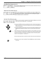
Extron’s Warranty
Extron Electronics warrants the product against defects in materials for
a period of two years and defect in workmanship for a period of two
years from the date of purchase. In the event of malfunction during the
warranty period attributable directly to faulty workmanship and/or
materials, Extron Electronics will, at its option, repair or replace said
products or components, to whatever extent it shall deem necessary to
restore said product to proper operating condition, provided that it is
returned within the warranty period, with proof of purchase and
description of malfunction to:
Extron Electronics
1230 South Lewis Street
Anaheim, CA 92805, U.S.A.
This Limited Warranty does not apply if the fault has been caused by
misuse, improper handling care, electrical or mechanical abuse,
abnormal operating conditions or non-Extron authorized modification to
the product.
______ If it has been determined that the product is defective, please call
Extron and ask for an Applications Engineer at (714) 491-1500 to
receive an RA# (Return Authorization number). This will begin the
repair process as quickly as possible.
Units must be returned insured, with shipping charges prepaid.
If not insured, you assume the risk of loss or damage during shipment.
Returned units must include the serial number and a description of the
problem, as well as the name of the person to contact in case there are
any questions.
Extron Electronics make no further warranties either expressed or
implied with respect to the product and its quality, performance,
merchantability, or fitness for any particular use. In no event will Extron
Electronics be liable for direct, indirect, or consequential damages
resulting from any defect in this product even if Extron Electronics has
been advised of such damage.
Please note that laws vary from state to state, and that some
provisions of this warranty may not apply to you.
SM
EXTRON ELECTRONICS / RGB SYSTEMS, INC.
1230 South Lewis Street, Anaheim, CA 92805
(800) 633-9876 (714) 491-1500 FAX (714) 491-1517
U.S.A.
EXTRON ELECTRONICS, EUROPE
Beeldschermweg 6C, 3821 AH Amersfoort
+31-33-453-4040 FAX +31-33-453-4050
The Netherlands
EXTRON ELECTRONICS, ASIA
41B Kreta Ayer Road, Singapore 089003
+65-226-0015 FAX +65-226-0019
Singapore
Contents
Chapter 1 - Introduction to the Matrix 200
General .......................................................................................................................... 1-1
I/O Modules ...................................................................................................... 1-1
Configurations ................................................................................................... 1-1
Standard Features ......................................................................................................... 1-2
Optional Features .......................................................................................................... 1-3
Front Panel Controller (FPC) ............................................................................. 1-3
QuickSwitch Front Panel Controller (QS-FPC) .................................................. 1-4
Redundant Power Supply (optional) .................................................................. 1-4
Sample Configuration .................................................................................................... 1-5
Matrix 200 I/O Module Specifications ............................................................................. 1-6
Chapter 2 - Hardware Installation
IEC Power Panel ............................................................................................................ 2-1
Standard Power Supply ..................................................................................... 2-1
Redundant Power Supply (optional) .................................................................. 2-1
Front Panel Controller ....................................................................................... 2-1
QuickSwitch Front Panel Controller ................................................................... 2-1
Removing the Matrix 200 Cover ..................................................................................... 2-2
Changing Matrix Front Panels ........................................................................................ 2-2
Installing a Front Panel Controller ..................................................................... 2-3
Replacing a Blank Panel with a QuickSwitch Front Panel Controller ................. 2-4
Installing a Blank Front Panel ............................................................................ 2-5
Installing the FPC for Remote Operation ........................................................................ 2-6
Changing the Main Fuse ................................................................................................ 2-6
RS-232/RS-422 Communications .................................................................................. 2-7
9-Pin RS-232/RS-422 Connector ...................................................................... 2-7
RS-232/RS-422 Protocol ................................................................................... 2-7
Swapping the RS-232/RS-422 Port Cable ......................................................... 2-7
Checksum Disable Jumper ............................................................................................ 2-8
Enabling the Part Number Jumper ................................................................................. 2-8
Installing the Security Jumper ........................................................................................ 2-8
Installing a Redundant (second) Power Supply .............................................................. 2-9
Before Installing I/O Modules ......................................................................................... 2-9
Adding an Audio Module ................................................................................. 2-10
Installing I/O Modules in the Rear Panel ......................................................... 2-13
Installing FPC/QS-FPC Software Update ........................................................ 2-15
Chapter 3 - Rear Panel Connections
Multi-Output Connection ................................................................................................ 3-1
Genlock Connections ..................................................................................................... 3-2
RGB Input Connections ................................................................................................. 3-2
RGB Input Connections with Right & Left Audio ............................................................. 3-3
RGBS Input Connections with Right & Left Audio .......................................................... 3-4
RGBHV Input Connections with Right & Left Audio ........................................................ 3-5
Composite Video Input Connections .............................................................................. 3-6
Composite Video Input with Right & Left Audio ................................................. 3-6
S-Video Input Connections ............................................................................................ 3-7
Input Connections ............................................................................................. 3-7
Output Connections .......................................................................................... 3-7
S-Video Input Connections with Right & Left Audio ........................................................ 3-8
Audio Terminal Connections ........................................................................................... 3-9
Audio Wiring Applications .................................................................................. 3-9
Extron • Matrix 200 • User’s Manual
i
Contents
Chapter 4 - Using the Front Panel Controller
Front Panel Controller (FPC) Operation ......................................................................... 4-1
Selecting Menus Using the SmartControl™ Keypad ...................................................... 4-2
Power On Message ........................................................................................................ 4-2
Tie Menu (default menu) ................................................................................................ 4-3
Using the LCD Display ................................................................................................... 4-3
How I/O Modules Are Handled ....................................................................................... 4-4
Changing Tie Submenus ................................................................................................ 4-5
Tie All Level ....................................................................................................... 4-5
Tie Group Level ............................................................................................................. 4-6
Tie Individual Level ........................................................................................................ 4-7
Menu Selection .............................................................................................................. 4-7
Using the Copy Menu (1) ............................................................................................... 4-8
Making Changes ............................................................................................... 4-8
Using the RGB Sync Delay Menu (2) ............................................................................. 4-8
Mute Output Menu (3) .................................................................................................... 4-9
Automating the Matrix 200 ........................................................................................... 4-10
Preset Menus (4) ......................................................................................................... 4-10
Load a Previously Saved Preset (menu 4) ...................................................... 4-10
Save the Current Routing as a Preset (menu 4) .............................................. 4-11
Sequence Menu (5) ..................................................................................................... 4-11
Create a Timing Sequence (menu 5) ............................................................... 4-12
Edit a Timing Sequence (menu 5) ................................................................... 4-12
Copying a Sequence (menu 5) ..................................................................................... 4-13
Start a Sequence (menu 5) ............................................................................. 4-13
Stop the Sequence (menu 5) .......................................................................... 4-13
Resume the Sequence (menu 5) .................................................................... 4-14
Delete a Sequence (menu 5) .......................................................................... 4-14
Program Menus (6) ...................................................................................................... 4-14
Program Start Time/Date (menu 6) ................................................................. 4-15
Program Delete (menu 6) ................................................................................ 4-15
Function Menu (7) ........................................................................................................ 4-16
Selecting Function Submenus ......................................................................... 4-16
Tie Level Access Submenu (menu 7) .............................................................. 4-16
Vertical Interval Switching Submenu (menu 7) ................................................ 4-16
Security Menu (8) ........................................................................................................ 4-17
Miscellaneous Menu (9) ............................................................................................... 4-18
Selecting Submenus ....................................................................................... 4-18
Display FPC Software Version Submenu (menu 9) ......................................... 4-18
Display Main Controller Software Version Submenu (menu 9) ........................ 4-18
Host Baud Rate Submenu (menu 9) ............................................................... 4-19
Show Clock Time & Date (menu 9) ................................................................. 4-19
Set Clock Time & Date (menu 9) ..................................................................... 4-19
Configure Audio Menu (0) ............................................................................................ 4-20
QuickSwitch Front Panel Controller (QS-FPC) Operation ............................................ 4-21
Power On Switch and LED .............................................................................. 4-21
Input and Output Buttons ................................................................................ 4-21
I/O Module Select Buttons .............................................................................. 4-22
Control Buttons ............................................................................................... 4-22
Ties, Configurations and Presets .................................................................... 4-24
Matrix 200 Configuration Worksheets .......................................................................... 4-25
Chapter 5 - Windows® Software Control
Extron Matrix Control Software ...................................................................................... 5-1
Windows Example ............................................................................................ 5-1
Matrix 100/200 Help ....................................................................................................... 5-3
ii
Extron • Matrix 200 • User’s Manual
Contents
Appendix A - Part Numbers, Glossary and Troubleshooting
Related Part Numbers ................................................................................................... A-1
Switcher Module Part Numbers ........................................................................ A-1
Option Kit Part Numbers ................................................................................... A-1
BNC-4 HR Cables (Mini High Resolution BNC Cables) ..................................... A-2
BNC Mini High Res Cable Specifications .......................................................... A-2
BNC-5 HR Cables ............................................................................................. A-2
Matrix 200 Part Numbering System ............................................................................... A-3
Glossary of Terms .......................................................................................................... A-4
Troubleshooting ............................................................................................................ A-12
Appendix B - Programming Guide
Control Ports .................................................................................................................. B-1
FPC Port ........................................................................................................... B-1
RS-232/RS-422 Control Port ............................................................................. B-1
Program Instruction Levels: Simple and Advanced ........................................................ B-1
Host/Matrix Data Format ................................................................................................ B-2
Binary/hex/decimal Conversion Table ................................................................ B-2
Simple Instruction Set .................................................................................................... B-3
Related Terms ................................................................................................... B-3
Simple Instruction List ....................................................................................... B-4
Advanced Instruction Set Command Structure .............................................................. B-5
Command Specifier .......................................................................................... B-5
Data .................................................................................................................. B-5
Checksum ......................................................................................................... B-5
End of Transmission .......................................................................................... B-5
Host-Initiated Communications Protocol ........................................................................ B-6
Error Codes (Erc) .............................................................................................. B-6
Matrix-Initiated Communications Protocol ...................................................................... B-6
Timing ............................................................................................................... B-6
Command List (Host-to-Matrix) ......................................................................... B-7
Reports (Matrix-to-Host) ................................................................................... B-7
Communication Control ..................................................................................... B-7
Using Commands .......................................................................................................... B-8
CMD0 (30h) - Send Status ................................................................................ B-8
CMD1 (31h) - Report ID .................................................................................... B-9
CMD2 (32h) - Turn Power On ............................................................................ B-9
CMD3 (33h) - Turn Power Off .......................................................................... B-10
CMD4 (34h) - Send Software Version ............................................................. B-10
Set (Tie) Connection Commands ................................................................................. B-11
Planes and Plane Maps .................................................................................. B-11
CMD5 (35h) - Set (Tie) Connection ................................................................. B-12
CMD7 (37h) - Set (Tie) All Connections .......................................................... B-12
CMD8 (38h) - Download Status and Presets .................................................. B-13
CMD9 (39h) - Mute All Planes ......................................................................... B-13
CMD10 (3Ah) - Save Current as Preset # ....................................................... B-13
CMD11 (3Bh) - Load Preset # ......................................................................... B-13
CMD12 (3Ch) - Mute Selected Outputs .......................................................... B-14
CMD13 (3Dh) - Request Mute Map ................................................................. B-14
CMD14 (3Eh) - Set Sequence ........................................................................ B-14
CMD15 (3Fh) - Request a Stored Sequence .................................................. B-15
CMD16 (40h) - Operate Sequence # .............................................................. B-15
CMD17 (41h) - Request a List of Presets ....................................................... B-15
CMD18 (42h) - Set Program ........................................................................... B-16
CMD19 (43h) - Request the Current Program ................................................. B-16
Extron • Matrix 200 • User’s Manual
iii
Contents
CMD20 (44h) - Operate Program .................................................................... B-16
CMD22 (46h) - Set Clock ................................................................................ B-16
CMD23 (47h) - Request the Clock Information ................................................ B-17
CMD24 (48h) - Turn Executive Mode On/Off ................................................... B-17
CMD25 (49h) - Set RGB Delay ....................................................................... B-17
CMD26 (4Ah) - Request RGB Delay Information ............................................ B-17
CMD27 (4Bh) - Set Baud Rate ........................................................................ B-18
CMD28 (4Ch) - Download Baud Rate ............................................................. B-18
CMD29 (4Dh) - Set Operating Mode ............................................................... B-18
CMD31 (4Fh) - Set Slave Coordinates ............................................................ B-19
CMD32 (50h) - Request Slave Coordinates .................................................... B-19
CMD33 (51h) - Identify Port ............................................................................ B-19
CMD34 (52h) - Set Security Passcode ........................................................... B-19
CMD35 (53h) - Operate Security .................................................................... B-20
CMD36 (54h) - Set Audio Parameters ............................................................. B-20
Configure Audio Inputs .................................................................................... B-21
Configure Audio Outputs ................................................................................. B-21
CMD37 (55h) - Request Audio Parameters ..................................................... B-22
Reports (Matrix-to-Host) .............................................................................................. B-23
Report0 (70h) - Status .................................................................................... B-23
Report1 (71h) - New Controlling Port .............................................................. B-23
Legend of Icons
The following icons may be used in this manual:
___________ Important information – for example, an action or a step that must be done
before proceeding.
___________ A Warning – possible dangerous voltage present.
___________ A Warning – possible damage could occur.
___________ A Note, a Hint, or a Tip that may be helpful.
___________ Possible Electrostatic Discharge (ESD) damage could result from touching
electronic components.
___________ Indicates word definitions. Additional information may be referenced in another
section, or in another document.
Matrix 200 User’s Manual
68-126-01, Rev. A
Rev. B, 59-03
Rev. C, 69-03, added Chapter 5
Rev. C1, 79-03, new format
Rev. D, 79-08
Written and printed in the USA
iv
Extron • Matrix 200 • User’s Manual
Matrix 200
User’s Manual
1
Chapter One
Introduction to the Matrix 200
I/O Modules
Configurations
Standard Features
Optional Features
Matrix 200 Module Specifications
Chapter 1 • Introduction to the Matrix 200
General
Each Extron Matrix 200 is custom designed to the user’s specifications. The
configuration is built from various combinations of ten I/O modules. The I/O
modules and possible configurations are listed below. The Matrix 200 can be
controlled from a host computer, a Front Panel Controller (FPC), or a
QuickSwitch™ Front Panel Controller (QS-FPC).
Matrix units can also be interconnected to expand the switching capabilities for
up to 48 inputs by 48 outputs. This allows for multiple switching combinations.
I/O Modules
Matrix 200 Switchers are ordered for a specific application with a combination of
I/O modules. Each module switches one type of video signal – one for red, one
for blue, etc. One audio module switches both left and right stereo channels.
•
•
•
•
•
•
•
•
•
•
4 x 4 High-Resolution Analog Module (HRAM), with 250 MHz video bandwidth
8 x 4 High-Resolution Analog Module (HRAM), with 250 MHz video bandwidth
8 x 8 High-Resolution Analog Module (HRAM), with 250 MHz video bandwidth
4 x 4 Sync Module
8 x 4 Sync Module
8 x 8 Sync Module
4 x 4 Video Module
8 x 4 Video Module
8 x 8 Video Module
8 x 8 Stereo Audio Module
For example: a Matrix 200 designed to switch RGB, separate horizontal and
vertical sync, and stereo audio, will require the following modules: three HRAM,
two Sync and one audio modules.
Configurations
Depending upon the configuration of I/O modules (above), the Matrix 200
Switcher can have up to 16 different input/output configurations. The
configuration determines how many modules are required.
•
•
•
•
•
•
•
•
•
•
RGsB
RGBS
RGBHV
RGsBCv
RGsBYC
RGBSCv
RGsBA
RGBSA
RGBHVA
RGsBCvA
• RGsBYCA
• RGBSCvA
•
•
•
•
1-1
CvA
YCA
Cv
YC
Red, Green, (sync on green), Blue
Red, Green, Blue and separate composite Sync
Red, Green, Blue and separate H&V Sync
Red, Green, (sync on green), Blue, and Composite video
Red, Green, (sync on green), Blue and S-Video
Red, Green, Blue, composite Sync, and Composite video
Red, Green, (sync on green), Blue, and stereo Audio
Red, Green, Blue, Sync, and stereo Audio
Red, Green, Blue, separate H&V sync, and stereo Audio
Red, Green, (sync on green), Blue, Composite video, & stereo
Audio
Red, Green, (sync on green), Blue, S-Video, & stereo Audio
Red, Green, Blue, composite Sync, Composite video, & stereo
Audio
Composite video, and stereo Audio
S-Video with stereo Audio
Composite video
S-Video
Extron • Matrix 200 • User’s Manual
Chapter 1 • Introduction to the Matrix 200
Standard Features
•
•
•
•
•
•
•
•
Microprocessor control, with battery backup
RS-232/RS-422 control
Complete breakaway
Composite and S-Video Genlock
RGB video delay switching
Separate video and audio mute
Security Lockout
250 MHz bandwidth
Microprocessor Control
The Matrix 200 is programmable from a host system, or from the optional Front
Panel Controller. It uses memory to store configurations and a calendar/clock to
activate these preset configurations at a specific date and time. The battery
backup prevents loss of preset information.
RS-232/RS-422 Control
The Matrix 200 can be controlled by any remote control system or computer with
RS-232/RS-422 serial communications capability. Refer to Appendix B for
programming guidelines including a complete listing of RS-232/RS-422
communications protocol.
Complete Breakaway
The complete breakaway feature of the Matrix 200 allows the user to program
any Video, S-Video or Audio Channel to be controlled separately (breakaway) or
as a group (follow one or more inputs, or all RGB inputs). A fully populated
RGBS composite video and audio switcher can be controlled as three separate
switchers.
Complete breakaway allows individual video or audio outputs to follow any one
or more RGBS inputs when switched to an output channel. This makes the
Matrix 200 capable of adding audio to any or all RGBS or video channels, as well
as allowing switchable video and audio to follow any switched RGBS channel.
Video Genlock
The Matrix 200 features a broadcast quality NTSC/PAL/SECAM Composite
Video or S-Video Genlock for synchronized switching of signals. The Matrix 200
will Genlock as many composite video signals as are installed in the switcher.
RGB Delay Switching
The Matrix 200 can be programmed to delay switching the RGB video for 1 to 9
seconds after the sync is switched. This allows the display device to be in sync
before the picture arrives, providing seamless switching of the RGBS signals
when switching between various frequencies.
Video and Audio Mute
The Matrix 200 provides separate mute controls to easily mute (turn off) the
RGBS or audio signals. Mute can be programmed to operate independently on
different outputs, or all outputs can be muted simultaneously with a single button.
Security Lockout
Matrix 200 programs can be protected by denying access through the RS-232
port, as well as through the Front Panel. Access is allowed only with a security
passcode.
Executive Mode
The Matrix 200 front panel buttons can be enabled/disabled to restrict Matrix 200
configuration changes.
250 MHz Bandwidth
Even when fully populated, the Matrix 200 has a bandwidth of no less than 250
MHz (-3 dB).
Extron • Matrix 200 • User’s Manual
1-2
Chapter 1 • Introduction to the Matrix 200
Optional Features
•
•
•
•
Front Panel Controller (FPC)
SmartControl microprocessor
QuickSwitch™ Front Panel Controller (QS-FPC)
Redundant power supply
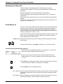
Front Panel Controller (FPC)
The Front Panel Controller (FPC) provides local control of all Matrix 200 Switcher
functions. It is supplied as an optional accessory to the Matrix 200 and is
intended for users who wish to supplement normal RS-232/RS-422 computer
control with local or remote operator control. For even greater flexibility, two
FPCs can be connected to the same Matrix 200 - one mounted to the front of the
Matrix 200 and the other located remotely. Refer to Chapter 2 for instructions on
mounting the FPC, and to Chapter 4 for FPC operation. The FPC includes the
following features:
Control Microprocessor
“SmartControlTM” is the Front Panel’s built-in microprocessor. It determines the
Matrix 200 input/output configuration, what presets are saved, as well as all other
switcher settings. SmartControl effectively configures the Matrix 200.
Trouble Status Indication The SmartControl microprocessor continuously monitors Matrix status, and also
alerts the user to any problems that may have occurred, such as: loss of power
(if the Matrix 200 has the optional redundant power supply) or loss of front panel
control when using the optional FPC. This helps isolate any equipment
malfunction quickly.
Configuration Memory
SmartControl can store up to 20 different connection configurations (called
presets). This can save hours of reprogramming each I/O configuration. The
Front Panel Controller (FPC) allows for easy configuration of inputs and outputs,
as well as the control of additional system features.
Two separate FPCs can be used to control one Matrix 200 switcher. For
example, a second FPC could be used to control the switcher from as far away
as 200 feet. When controlling the switcher via RS-232/RS-422, the FPC may or
may not be needed.
LCD Menu-driven
SmartControl
1-3
The Front Panel includes a lighted, liquid crystal display (LCD) that is used to
step through the setup and program functions necessary to install and operate
the Matrix 200. A full complement of function buttons makes setup and
programming of the unit fast and easy.
Extron • Matrix 200 • User’s Manual
Chapter 1 • Introduction to the Matrix 200
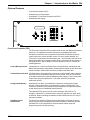
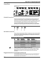
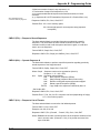
INPUTS
1
2
3
1
2
3
4
5
4
5
6
6
7
8
7
8
ENTER
PRESET
VIEW
ESC
RGBS
VIDEO
AUD 1
AUD 2
OUTPUTS
QS - FPC
MATRIX SWITCHER
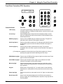
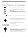
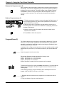
QuickSwitch™ Front Panel Controller (QS-FPC)
The QuickSwitch Front Panel Controller (QS-FPC) provides local control of all
Matrix 200 Switcher functions. It is supplied as an optional accessory to the
Matrix 200 and is intended for users who wish to supplement normal RS-232
computer control with local or remote operator control. Refer to Chapter 2 for
instructions on mounting the QS-FPC, and to Chapter 4 for QS-FPC operation.
The QS-FPC includes the following features:
Control Microprocessor SmartControlTM is the Front Panel's built-in
microprocessor. With it, the user determines the Matrix 200 input/output
configuration, what presets are saved, as well as all other switcher settings.
Configuration Memory SmartControl can store up to eight different matrix
configurations (called presets). This can save hours of reprogramming each I/O
configuration. The QuickSwitch Front Panel Controller (QS-FPC) allows for easy
configuration of inputs and outputs, as well as the control of additional system
features.
QuickSwitch SmartControl The Front Panel’s full complement of function buttons
makes setup and programming of the unit fast and easy.
Redundant Power Supply
The Matrix 200 can be ordered with an optional redundant (backup) power
supply to prevent signal loss if input power to the primary power supply should
suddenly be lost or interrupted.
Extron • Matrix 200 • User’s Manual
1-4
Chapter 1 • Introduction to the Matrix 200
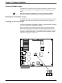
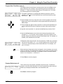
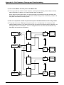
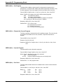
Sample Configuration
The picture here shows one example of the I/O modules that could be installed in
six planes of a Matrix 200. See page 1-1 for I/O modules and possible
configurations.
For example, an 8 x 8 RGBS switcher requires: three 8 x 8 high-resolution
analog modules (HRAM) and one 8 x 8 sync module (Syn). This would occupy
the Red, Green, Blue and one Sync/Video planes. The fifth plane could have a
composite video module (Cv), and the sixth plane could have an audio switching
module (Aud).
This configuration is capable of being
controlled and routed as three
separate switchers:
• one 8 x 8 RGBS matrix switcher
• one 8 x 8 video switcher
• one 8 x 8 audio switcher
In addition, SmartControl™ allows
the Matrix 200 to group these
functions as a single RGBS
composite video switcher with stereo
audio.
The bottom of the diagram illustrates
how the Main Controller (and the
optional Front Panel Controller)
routes the various inputs to the
outputs.
1-5
Extron • Matrix 200 • User’s Manual
Chapter 1 • Introduction to the Matrix 200
Matrix 200 I/O Module Specifications
Power .
Dimensions .
.
Shipping Weight .
Operating Temperature .
Storage Temperature .
MTBF .
Approved .
Warranty .
100 - 240 VAC, 50/60 Hz, 60 Watts
17" W, 15" D, 6.8" H
43 cm W, 38 cm D, 17 cm H
22 lbs (10 kg)
0° C - 50° C
-20°C - 70° C
35,000 Hours (demonstrated)
CE, UL, CUL Listed
2 years, parts and labor
HRAM Video (High Resolution Analog Module)
Connectors . BNC
Bandwidth . 250 MHz (-3 dB)
Crosstalk:
at 10 MHz . -50 dB(typical) See note 1.
at 100 MHz . -30 dB
at 200 MHz . -30 dB
Isolation:
at 10 MHz . -60 dB (typical) See note 2.
at 100 MHz . -55dB
Return Loss:
at 10 MHz . -20 dB
at 200 MHz . -50 dB
Input Impedance . 75 ohms
Output Impedance . 75 ohms
Switching Speed . 200 ns (nominal)
Input Signal . 0.3-1.0 V p-p (max dc offset ± 0.30 V)
Gain . Unity ±1%
Note 1: Crosstalk is the
attenuation of all hostile
signals relative to a given
input-output connection.
Note 2: Isolation is the
attenuation of an input signal
relative to an unselected
output when all inputs have
the same signal applied
simultaneously.
Composite Video Module
Frequency Response .
Differential Gain .
Differential Phase .
Line and Field Tilt .
Isolation Between Outputs .
Crosstalk .
CMRR .
Propagation Delay .
Input Signal .
.
Gain .
-0.5 dB @ 5 MHz; -3.0 dB @ 15 MHz
0.5%
1.3°
Less than 0.1%
Greater than 40 dB @ 5 MHz
Greater than 40 dB @ 5 MHz
-60 dB
10 ns
75 ohms, analog, 0-1.0 V p-p
(max dc offset ±0.30 V)
Unity
Sync Module
Input Impedance .
Output Impedance .
Max. Input Voltage .
Input Sensitivity .
Output Level .
.
Max. Propagation Delay .
Max. Rise/Fall Time .
Polarity .
Extron • Matrix 200 • User’s Manual
510 ohms
75 ohms
±5 V
500 mV p-p
4.5 V p-p not terminated;
2.2 V p-p terminated at 75 ohms
64 ns H to L (41 ns L to H)
8 ns H to L (3.6 ns H to L)
Follows input
1-6
Chapter 1 • Introduction to the Matrix 200
Audio Module, General
Input Impedance . High Z (>10k ohms, typical)
Input Voltage Level . To 6 V p-p into 600 ohms
Output Impedance . Low, capable of driving 600 ohms, balanced
Output Level . Near zero to unity gain
Connectors . 6-conductor, Phoenix® Captive Screw Terminal
Signal to noise . Better than 110 dB, 20Hz-20kHz
Total Harmonic Distortion + Noise . Worst case 0.03% @ 20kHz, 30 V p-p
. (Differential Output)
Adjacent Channel Crosstalk . Better than -85 dB @ 20kHz
Common Mode Rejection Ratio . -55 dB worst case @ 20kHz (-65 dB Typical)
Stereo Channel Separation . Greater than 60 dB 20 Hz - 20kHz
Bandwidth . 20Hz - 20kHz, Flat ± 0.1 dB
Audio Input Specifications
Professional Mode Attenuation . 20 dB
Consumer Mode Attenuation . 0 dB
Maximum Input Level:
Professional Mode . 60 V p-p Differential; 60 V p-p Single-ended
Consumer Mode . 6 V p-p Differential; 6 V p-p Single-ended
Nominal Input Program Level:
Professional Mode . +4 dBu (1.2 V rms)
Consumer Mode . -10 dBu (300 mV rms)
User Controllable Input Gain . +31.5 dB Gain
. -95.5 dB Attenuation
(In 1 dB steps, using FPC; in 0.5 dB steps, using Serial interface)
Input Impedance . 10 k ohms, Differential to Ground
Audio Output Specifications
Professional Mode Gain . 14 dB
Consumer Mode Gain . 0 dB
Maximum Output Level:
Professional Mode . 60 V p-p Differential; 30 V p-p Single-ended
Consumer Mode . 12 V p-p Differential; 6 V p-p Single-ended
Nominal Output Program Level:
Professional Mode . +4 dBu (1.2 V rms)
Consumer Mode . -10 dBu (300 mV rms)
Stereo Channel Directing: .
.
Channel swap .
.
Left Input to Left & Right Output
Right Input to Left & Right Output
Right Input to Left Output;
Left Input to Right Output
Output Impedance . 50 ohms, Differential to Ground
1-7
Extron • Matrix 200 • User’s Manual
Chapter 2 • Hardware Installation
Matrix 200
User’s Manual
2
Chapter Two
Hardware Installation
IEC Power Panel
Removing the Matrix 200 Cover
Installing Front Panels (local & remote)
RS-232/RS-422 Connections
Installing Redundant Power Supply
Installing Security Feature
Installing I/O Modules
Extron • Matrix 200 • User’s Manual
Chapter 2 • Hardware Installation
This chapter covers only the installation of the Matrix 200 hardware. Connecting
its inputs and outputs is covered in Chapter 3 and setup is covered in Chapter 4.
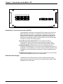
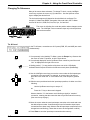
IEC Power Panel
The IEC Power Panel consists of an On/Off switch, a fuse cover and two male
power connectors. The second connector is provided for a redundant power
supply.
Standard Power Supply
The Matrix 200 Series switcher/router has an auto-switching power supply that
operates from any input voltage from 90 to 260 VAC, 50/60 Hz. No equipment
changes are necessary.
Fuse
REDUNDANT POWER
FUSE: 250V ~0.8A TT
AC POWER INPUT
Fuse Type = 5mm x 20mm
Fuse Rating = 250V, 0.8A Super Slo Blo
Power Switch
!
100-240V ~0.5A MAX 50/60 Hz
DISCONNECT ALL POWER CORDS BEFORE SERVICING
Power Switch -
1 = On
0 = Off
Redundant Power Supply (optional)
To improve equipment reliability in critical applications, the Matrix 200 can be
configured with a redundant internal power supply. With this option, the
Matrix 200 will automatically switch to the backup supply if the primary supply
fails. If the Matrix 200 switches to the backup power supply, it continues to
operate without interruption and sends a command to the Host system to
indicate a change in status. If the Matrix has a Front Panel Controller or
QuickSwitch Front Panel Controller, the Power LED will flash to alert the user
that a power failure has occurred.
_______ To install this optional power supply, see procedure on page 2-9.
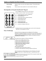
Front Panel Controller
The Front Panel Controller (FPC) provides local control of all Matrix 200
functions. This optional feature is intended to supplement normal RS-232/
RS-422 computer control with a local or remote operator control. As described in
the following pages, the FPC can either be mounted on the front of the
Matrix 200 or installed remotely, up to 200 feet, by means of an RJ45 cable
connected to the rear panel.
Two FPCs can be connected to the same Matrix 200 - one on the front and the
other located remotely and connected to the rear panel of the Matrix 200. Refer
to the following pages for instructions for mounting and connecting the FPC to
the Matrix 200.
_______ The following pages include procedures for panel installation.
QuickSwitch Front Panel Controller
The QuickSwitch Front Panel Controller (QS-FPC) provides local control of all
Matrix 200 functions. This optional feature is intended to supplement normal
RS-232 computer control with a local or remote operator control.
2-1
Extron • Matrix 200 • User’s Manual
Chapter 2 • Hardware Installation
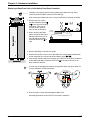
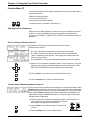
Removing the Matrix 200 Cover
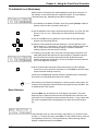
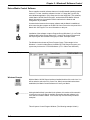
As a preliminary step, follow this procedure when making any hardware
changes which require access to the interior of the Matrix 200 unit.
Caution: The ambient temperature of the rack should not exceed 50° C. To insure proper
ventilation, we recommend that you allow a minimum of one rack unit spacing
above and one below the Matrix 200 if forced air cooling is not used.
1. Turn off input power to the Matrix 200; disconnect power cord(s).
2. If the Matrix 200 is rack-mounted, remove it and place it on a clean
workspace.
3. Remove the six screws that hold the top half of the Matrix cover. Lift the
cover-half straight up to expose the main controller board inside. (See
picture)
Note: When changing a front panel, the
side panels may move when the panel is
off, misaligning the panel screws with the
mounting holes. With the top cover off,
move the sides, if necessary, to align the
holes. After the new front panel is
mounted, replace the top cover.
4. Go to the appropriate installation
procedure.
Caution:
Take care to remove the four spacers
from the rear of the panel.
Changing Matrix Front Panels
All Matrix 200 units ship with either a Front Panel Controller (FPC), a
QuickSwitch Front Panel Controller (QS-FPC), or a Blank Front Panel. There
may be a need to change this configuration, such as:
• If the FPC or QS-FPC is to be removed, for example to install it remotely, a
blank front panel must be installed in its place.
• If the Matrix 200 Series Switcher is presently configured with the blank front
panel and the optional FPC or QS-FPC is to be installed.
If there is a need to change this configuration, refer to “Removing the Matrix 200
Cover” (above), and use the appropriate procedure from the following page.
Extron • Matrix 200 • User’s Manual
2-2
Chapter 2 • Hardware Installation
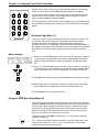
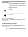
Installing a Front Panel Controller
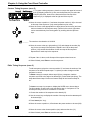
Remove the cover (see “Removing the Matrix 200 Cover” on page 2-2) and then
do the following:
1. Remove the four
No.10 screws and
dress washers (items
&
) from the
Blank Front Panel.
Caution:
Take care to remove the four spacers from the rear of the panel. See picture
below, left.
2. Disconnect the Power Indicator cable from J13 on the right side of the main
controller board and remove the panel. See
in the picture below right.
3. Position the FPC on the front of the Matrix 200, with a spacer behind each
screw. Install the four screws and dress washers (items
& ). This may
be made easier by placing the Matrix face-up, being careful to protect the
BNC connectors from damage.
4. Connect the modular
cable from the plug on
the FPC to the RJ45
connector on the
Matrix 200 main
controller board. See
in the picture to the right
for connector location.
Black
Red
5. Reverse the above
procedure to put the
Matrix back together.
_______ When installing a new front
panel, it may be necessary to reposition the side panels to align the screw
holes.
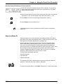
The mounted Front Panel Controller.
2-3
Extron • Matrix 200 • User’s Manual
Chapter 2 • Hardware Installation
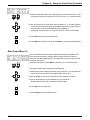
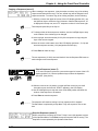
Replacing a Blank Panel with a QuickSwitch Front Panel Controller
_______ Installing a front panel may be easier by placing the Matrix face-up, being
careful to protect the BNC connectors from damage.
After removing the Matrix 200 cover, remove the Blank Front Panel as follows:
1. Remove the four screws
and dress washers (items
&
at left) from the existing
front panel. Take care to
remove the four spacers
from the rear of the panel.
2. When removing the blank
panel, disconnect the Power
Indicator cable from J13 on
the right side of the Main
Controller board. See
at
right.
LITHIUM
BATTERY
3. Remove the Blank Front and set it aside.
4. Position the QS-FPC on the front of the Matrix 200, with a spacer behind each
& ).
screw. Install the four screws and dress washers (items
5. Connect the modular cable from the plug on the QS-FPC to the RJ45 connector
on the Matrix 200 Main Controller board. See
in the picture above for the
RJ45 connector location.
___ Circuits may be damaged by using the wrong RJ45 cable. See figure below for
correct orientation of cable conductors.
6. Refer to page 2-2 when reassembling the Matrix 200.
Operating instructions for the QS-FPC are found in Chapter 4.
Extron • Matrix 200 • User’s Manual
2-4
Chapter 2 • Hardware Installation
Installing a Blank Front Panel
Remove the cover (see “Removing the Matrix 200 Cover” on page 2-2) and then
do the following:
1. Disconnect the modular cable from the plug on the FPC to the RJ45 connector
on the Matrix 200 main controller board. See in the picture below for the
connector location.
2. Remove the four
No.10 attaching
screws and dress
washers (items
&
in pictures below)
from the front panel
and remove the
panel.
Caution:
Take care to remove the four spacers from the rear of the panel. See picture
below, left.
3. Position the blank panel on the front of the Matrix 200 with a
spacer behind the panel for each screw. Install the four screws and
dress washers. (See
&
in left picture.) This may be made
easier by placing the Matrix face-up, being careful to protect the
BNC
connectors
from damage.
4. Connect the
Power Indicator
cable from the
Blank Front Panel to J13
on the right side of the
main controller board.
See
in the picture to
the right.
Black
Red
5. Reverse the procedure for
removing the cover to
reassemble the Matrix.
_______ When installing a new front
panel, it may be necessary to reposition the side panels to align the screw
holes.
If the FPC is to be installed remotely, refer to
the following procedure.
2-5
Extron • Matrix 200 • User’s Manual
Chapter 2 • Hardware Installation
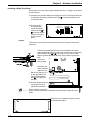
Installing the FPC for Remote Operation
The rear panel of the Matrix 200 has an 8-conductor RJ45 connector used to
plug a cable from a remote FPC. The remote FPC can be used independently, or
as a second FPC, in parallel with one mounted to the front of the Matrix 200. The
use of one or more FPCs does not interfere with normal RS-232/RS-422 control
of the Matrix 200 switcher.
The diagram below shows the cable connection from the remote FPC to the
Matrix 200. The remote panel can be mounted in another rack, or any convenient
location.
c
O
U
T
P
U
T
S
O
U
T
P
U
T
S
8-conductor
8-conductor
cable,upup
cable,
to to
100feet
feet
200
LISTED
1T23
ITE
O
U
T
P
U
T
S
Changing the Main Fuse
To change the AC power fuse, you must first unplug the IEC power cable. This
FUSE: 250V ~0.8A TT
AC POWER INPUT
allows access to the fuse holder. Use a small, flat
screwdriver to press into the notch and pull the holder
straight out. There is a storage place for a spare fuse.
Replace the blown fuse* (see picture right) and slide the
fuse holder until it snaps in place.
There is also an AC fuse on each of the two boards that
make up the power supply. Each fuse is located next to
the AC input connector. These fuses are accessible by
removing the top cover of the Matrix.
* Use 250V, 0.8A Super Slo Blo Fuse
Extron • Matrix 200 • User’s Manual
2-6
Chapter 2 • Hardware Installation
RS-232/RS-422 Communications
The Matrix 200 can be controlled by a host system through an RS-232/RS-422
interface. The interface allows the user to write programs to configure and
automate the operation of the Matrix 200. This includes making changes
dynamically when commanded by the host controller and when informing the
host of the Matrix status. Certain important changes in status are reported to the
host automatically. For additional programming information, refer to Appendix B.
9-Pin RS-232/RS-422 Connector
The RS-232/RS-422 connector is a standard 9-pin D subminiature female
receptacle with the following pin designations:
REDUNDANT POWER
!
1
DISCONNECT
Pin
RS-232
1
2
3
4
5
6
7
8
9
—
Tx
Rx
—
Gnd
—
—
—
—
Description
RS-422
Description
No Connection
Transmit Data
Receive Data
No Connection
Signal Ground
No Connection
No Connection
No Connection
No Connection
TxD (-)
TxD (+)
Rx (+)
Rx (-)
Gnd
—
—
—
—
Transmit Data (-)
Transmit Data (+)
Receive Data (+)
Receive Data (-)
Ground
No Connection
No Connection
No Connection
No Connection
RS-232/RS-422 Protocol
The RS-232/RS-422 baud rate is selectable from the Miscellaneous Menu, see
Chapter 4. The default protocol is 9600-baud, 8-bits, no parity, 1 stop bit, X-On/
X-Off.
Swapping the RS-232/RS-422 Port cable
The rear panel of the matrix has a single 9-pin connector labeled “RS-232”. The
Main Controller board provides two connectors – one for RS-232 and the other
for RS-422. Each matrix ships with the cable connected to the RS-232 port on
the Main Controller board. If your system uses RS-422, you may change this
connection on the Main Controller board as shown below. See page 2-2 for
instructions on removing the Matrix 200 cover.
2-7
Extron • Matrix 200 • User’s Manual
Chapter 2 • Hardware Installation
Checksum Disable Jumper
The Matrix 200 is shipped with JMP3 installed to disable the Checksum feature.
To enable it, remove the top cover (page 2-2) and remove JMP3. See picture
below.
_______ Note: When Checksum is disabled, the Cks1 and Cks2 bytes must still be
included. They must be data bytes (have a value between 80h and FFh).
Enabling the Part Number Jumper
The Matrix 200 reports its unit part number if the JMP4 jumper on the main board
is installed. This jumper has no other effect on the system and is factory set.
Installing the Security Jumper
The security code feature is described in Chapter 1, and implemented in Chapter
4, menu 8. It can only be used if JMP2 is installed.
Note: If the security is set and the code is not known, you cannot access the
Matrix. Remove this jumper and reinstall it to unlock the Matrix and reset the
code. At some point in time, power must be applied with the jumper out for the
controller to recognize this change. To reactivate the security feature, reinstall
JMP2 before putting the cover back on.
4
Black
Red
4
Extron • Matrix 200 • User’s Manual
2-8
Chapter 2 • Hardware Installation
Installing a Redundant (second) Power Supply
To install a redundant power supply in a Matrix 200, disconnect the power
source, remove the Matrix from its rack mount, and place it on a clean
workspace. Refer to page 2-2 to remove the cover. With the cabinet open, do the
following:
1. Mount the new power supply on the four bolts projecting up from the bottom of
the cabinet and secure it with four nuts. This position is parallel to that of the
primary power supply. (See dotted lines in picture.)
2. Connect the two twisted power cables from the second IEC connector to the
inputs on the new power supply boards. See dotted lines in picture below.
3. Connect the two black power output connectors to the two vacant connectors
on the main controller board - next to the connectors from the primary power
supply.
4. Check the mounting and connections by comparing them with those for the
primary power supply.
5. Put the Matrix 200 back together and connect both AC power sources.
DUNDANT POWER
!
FUSE: 250V ~0.8A TT
AC POWER INPUT
6. To check the operation of the redundant supply, turn the AC switch Off. The
Matrix should function normally using the redundant power supply. If using an
RS-232/RS-422 interface, the Matrix Status Bytes will indicate this condition.
100-240V ~0.5A MAX 50/60 Hz
DISCONNECT ALL POWER CORDS BEFORE SERVICING
Like the primary
power supply, the
redundant supply
has a 2-amp, fastblo fuse at the AC
input of each
board.
Black
Before Installing I/O Modules
Before adding an I/O Module to an existing Matrix 200, you must know the
revision status of the Matrix. Page A-1 has a list of option kits and their part
numbers. It also explains what upgrades may be required before adding
modules.
_______ If the serial number has an “A” after it, the Matrix is ready for an Audio Module.
If the unit does not meet these requirements, go to the appropriate procedure to
bring it up to date and then do the Audio Installation.
2-9
Extron • Matrix 200 • User’s Manual
Chapter 2 • Hardware Installation
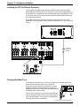
Adding an Audio Module
Tools for Installation:
3/16" flat screwdriver
#4 Phillips screwdriver
#6 Phillips screwdriver
Wire cutters
Audio Option Kit:
Qty Description
6
Internal Tooth Lock
Washers
1
Audio Module with:
1
3" Ribbon Cable
6
1-5/8 Screws
16 Phoenix Connectors
_______ Do not use this procedure unless your Matrix 200 is up to date. See previous
page.
1. Remove the Matrix top cover (procedure on page 2-2).
2. Locate the gray ribbon cables that connect the Main Controller board to the
existing I/O modules (Red, Green, Blue and Sync/Composite Video). Note the
orientation of the red stripe on each ribbon cable and unplug both ends. If
necessary, cut the ties that bind them together. It is not necessary to mark the
cable connections; this will be covered later. Place the ribbon cables
aside.
3. On the rear panel, remove the two screws (See
below)
that hold the right end of the blank cover. (Tabs hold the
left end.) Remove the cover and put the screws back in
the same holes. This reveals two long, parallel
access slots. These will
accommodate the upper
and lower sections of the
Audio Module.
Lock Washers
4.Check the installation
parts list and identify
them by their location in
the picture to the right.
Black
Red
Extron • Matrix 200 • User’s Manual
2-10
Chapter 2 • Hardware Installation
5. Unpack the Audio Matrix module and locate the following:
· The bracketed attachment is the power supply.
· Two rows of female Phoenix audio connectors,
eight in each row. Six pins per connector.
· Board address DIP switches. (See at right.)
· 3-inch ribbon cable attached. (Not visible in the
picture to the right.)
_______ The address DIP switches are factory-set. See right end of picture above. They
should be set to represent an address of five (0101 binary).
6. Remove the six nuts from the screws that hold the two boards together. Set
the screws and washers aside; the nuts will not be needed. (See above.)
7. Slide the rear panel upward about 3/4", while keeping it in the
cabinet grooves. (See right.)
8. Orient the Audio Module above the nylon
spacers, with the audio connector
strips to the rear. Tilt the module
slightly and slip the audio connectors
through the parallel openings in the
rear panel and lower it to a
horizontal position.
(See right.)
9. While holding the Audio Module in position
with the rear panel, lower them both
carefully until the module rests on the six nylon spacers. (See
below.)
10. With the Audio Module loosely in position, lift the corner by
the power supply slightly and plug the ribbon cable
into the nearest slot (J4) on the Main
Controller board.
_______ The I/O connectors on the Main Controller
board are on a parallel bus, therefore it
doesn't matter which module is plugged to
which connector. Because of its cable length,
the Audio Board must plug into the closest
connector.
2-11
Extron • Matrix 200 • User’s Manual
Chapter 2 • Hardware Installation
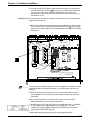
11. Plug the remaining I/O Ribbon cables from each module to a connector on
the Main Controller board (See below). Since the Main Board connectors
are the same, connect the cables for neatness and convenience. For
example, the illustration below shows the Red I/O module connected to J5,
the Green to J6, etc.
Warning: When working close to the other I/O modules, be careful that you do not change any
other DIP switch settings.
12. Be sure the cables are securely plugged into the Main board, and then drop
the six screws into the six holes in the Audio Module (See below). Wiggle
each screw by hand to align it with the threads below and tighten them with a
screwdriver.
Audio
Black
Red
_______ The red stripe on the ribbon cables (pin 1) is to the right, on the Main Controller
and Audio boards. (See the picture below.) It must point up on the other I/O
modules.
13. With all connections and screws secure, route the cables away from the
power supplies. Use tie wraps to tie cables together where they follow the
same path.
14. If no other modifications are required, put the top cover back on the
Matrix 200 and put it back in its working position.
If the Matrix has an FPC, the new Power On message will show “A” in position
6. See example. Other digits depend on the configuration. The new
configuration will also appear in Request ID information sent to the Host
system via the RS-232/RS-422 port.
If other modifications are required, go to the appropriate procedure.
Extron • Matrix 200 • User’s Manual
2-12
Chapter 2 • Hardware Installation
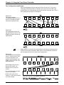
Installing I/O Modules in the Rear Panel
Tools for Installation:
3/16" flat screwdriver
#4 Phillips screwdriver
#6 Phillips screwdriver
9/16" Socket/nutdriver
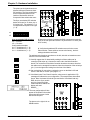
There are three types of modules that can be installed in the rear panel of the
Matrix 200: HRAM module, for RGB; Sync module, for Horizontal and/or Vertical
Sync; and Composite Video module for Composite Video or S-Video. Positions,
or “planes” 1, 2, and 3 will accommodate only HRAM modules. Planes 4 and 5
will accommodate either Sync or Composite video modules, but not HRAM. A
Matrix unit cannot have one or two HRAM modules; it must have three (for red,
green and blue) or none.
Use this procedure to install any HRAM, Sync or Composite Video module.
Locate the position on the back panel for the new module. An HRAM can only be
installed in the locations marked Red, Blue or Green. A Sync module or a
Composite Video module can only be mounted in the positions marked as such.
If there is one sync module, it must be in the first position after the Blue, or
Plane 4.
Configuration
RGsB
RGBS
RGBHV
RGBSCv
1 Cv
2 Cv or 1 YC
plane 1
HRAM
HRAM
HRAM
HRAM
-
plane 2
HRAM
HRAM
HRAM
HRAM
-
plane 3
HRAM
HRAM
HRAM
HRAM
-
plane 4
Sync
Sync
Sync
C-Video
C-Video
plane 5
Sync
C-Video
C-Video
Audio can be included with any of these combinations.
_______ Address switches are set according to the physical location.
The illustration here shows the modules already installed.
3
4
BLUE
SYNC/
VIDEO
SYNC/
VIDEO
c
O
U
T
P
U
T
S
O
U
T
P
U
T
S
LISTED
1T23
ITE
O
U
T
P
U
T
S
1
REDUNDANT POWER
1
2
4
1
2
4
!
2
FUSE: 250V ~0.8A TT
3
AC POWER INPUT
100-240V ~0.5A MAX 50/60 Hz
DISCONNECT ALL POWER CORDS BEFORE SERVICING
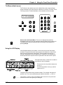
1. Remove the Matrix top cover (procedure on page 2-2).
2. Locate the gray ribbon cables that connect the Main Controller board to the
existing I/O modules and determine where the new module will be connected.
If cables from adjacent modules are in the way, they may be unplugged and
reconnected later.
3. On the rear panel, remove the 16 round plastic plugs that cover the holes
where the new module will be installed.
4. On the new module, remove the nuts from the 16 BNC connectors.
______ If installing both a Sync module and a Composite Video module, the Sync module must be in
Plane 4 and the Composite Video in Plane 5.
2-13
Extron • Matrix 200 • User’s Manual
The picture to the right shows some
physical differences between these
two modules. The Sync module has
some components placed on the
insides of the boards, while the
Composite Video module has none.
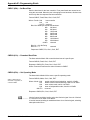
1
5
2
3
4
6
7
8
INPUTS
The Sync termination DIP switches
below will be set for 75 ohms (on) or
510 ohms (off). The switches (1 - 8)
correspond to the inputs on the right
(1 - 8).
OUTPUTS
1
2
3
4
5
6
7
8
on
off
8
7 6 5 4 3 2 1
Sync termination DIP switches
on = 75 ohms
off = 510 ohms
Configuration examples:
8 x 8 = 8 switches on (1 - 8)
8 x 4 = 8 switches on (1 - 8)
4 x 4 = 4 switches on (1 - 4)
Sync termination DIP switches
ê
Chapter 2 • Hardware Installation
5. Mount the module by inserting the BNC connectors through the
holes in the rear panel and secure it in place with the 16 nuts. (Use
9/16" socket.)
6. Verify that the address DIP switches are set for the correct
Plane number. These switches are set at the factory, but their
settings should be confirmed.
The address switch settings are shown to the left, with their orientation as seen
from the front of the Matrix 200.
Red
Green
Blue
Sync/Video
Sync/Video
7. Carefully support the I/O board while pushing the ribbon cable onto its
connector (Red stripe up). Connect the other end to the Main Controller
board. The connectors on the Main Controller board are the same, therefore
the cables can be arranged for neatness. Note the orientation of the red stripe
(pin 1) is to the right when looking from the front of the Matrix.
8. After rechecking all connections, replace the cover on the Matrix 200 and
secure it with the six screws. (See page 2-2.)
9. If the Matrix has a Front Panel Controller, when power is applied the LCD
message will indicate the new configuration. The example here shows Red,
Green, Blue, Horizontal & Vertical Sync and Audio. If the Matrix had only
RGB, and one Sync module
and one Composite Video
module had been added, the
display will read:
RGBSC_ _.
The new configuration will also
appear in Request ID information
sent to the Host system via the
RS-232/RS-422 port.
The picture to the right is for an
HRAM module.
Extron • Matrix 200 • User’s Manual
2-14
Chapter 2 • Hardware Installation
Installing FPC/QS-FPC Software Update
1. If the FPC/QS-FPC is mounted on the Matrix 200, refer to the procedure on
page 2-2 to open the cabinet and then continue with step 2.
___________ Electro-Static Discharge (ESD) can damage IC chips, even when it is not
enough to be humanly detected (felt, heard or seen). Do NOT touch IC chips
without being electrically grounded.
2. With the top cover off the Matrix, unplug the cable that connects the FPC/QSFPC to the Main Controller board and put it aside.
3. Remove the four (4) screws that hold the FPC/QS-FPC to the Matrix cabinet.
4. Place the FPC/QS-FPC face down on a clean workspace. If necessary, place
it on a soft pad to prevent damage.
5. Using a 1/4" nut driver, remove four (4) 1/4" nuts that hold the cover on the
back of the FPC/QS-FPC.
Black
Red
6. After first properly grounding yourself, use the PLCC IC puller to remove the
old Software chip. Squeeze the tool to align the hooks with the slots provided
in opposite corners of chip socket U8. Insert the hooks, squeeze gently and
pull the IC straight out of the socket. Set the chip aside.
7. Note the orientation of the angled corner of the new Software chip. Position
this to match the angled corner of the socket and carefully press it in place.
PLCC Chip Puller
8. Reinstall the cover on the back of the FPC/QS-FPC and reverse the above
procedure to put the Matrix back in place.
2-15
Extron • Matrix 200 • User’s Manual
Matrix 200
User’s Manual
3
Chapter Three
Rear Panel Connections
Multiple Output Connections
Genlock Connections
RGB Input Connections
Composite Video Input Connections
S-Video Input Connections
Audio Terminal Connections
Chapter 3 • Rear Panel Connections
Multi-Output Connection
When using the Matrix 200 to switch different types of video signals, the signal
output from the switcher is in the same format as the corresponding input. That
is, RGB and Sync (composite or separate H&V) signals will pass through the
RGB and SYNC output; NTSC and PAL video signals will pass through the
composite video output; and S-Video will pass through the S-Video output.
Therefore, if multiple input signal types are used in the same switcher, the same
multiple outputs must also be directed to the output devices.
In the diagram below, the Matrix 200 supplies RGB output for large screen
projectors and data monitors, composite video output for an LCD projector, and
audio output for a stereo audio system.
The following pages show possible connections.
3-1
Extron • Matrix 200 • User’s Manual
Chapter 3 • Rear Panel Connections
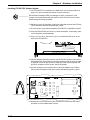
Genlock Connections
The Matrix 200 is
designed to use an
external Genlock signal
to synchronize composite
video or S-video
switching. If connected,
Genlock can be
programmed either from
the optional Front Panel
Controller, or from a Host
system (through the RS-232/
RS-422 port).
O
U
T
P
U
T
S
The illustration here shows the
Genlock connections. The
Genlock Out connector simply
allows the signal to be passed
on to another video device; it
does not have to be connected
for Matrix operation.
REDUNDANT POWER
!
FUSE: 250V ~0.8A TT
AC POWER INPUT
100-240V ~0.5A MAX 50/60 Hz
DISCONNECT ALL POWER CORDS BEFORE SERVICING
RGB Input Connections
All RGB input and output connections to the Matrix 200 are made with BNC type
connectors. Many types of RGB output devices (scan doublers, document
cameras, etc.), including most computers, do not have BNC video output
connectors. If not, a suitable adapter or an Extron computer-video interface
should be used to adapt the device output to the BNC input of the Matrix 200.
With the proper adapter, the RGB and Sync signals can be connected directly to
the R, G, B, H, V inputs of the switcher. If the RGB signal is using the Sync-onGreen channel, connect the RGB cables to the switcher without using the sync
channels.
RGB input connections to the Matrix 200 can be made using the following
combinations:
Without Audio
RGsB - Red, Sync-on-Green, Blue
RGBS - Red, Green, Blue, and Composite Sync
RGBHV - Red, Green, Blue, H&V Sync
With Audio
RGsB with R&L Audio - Red, Green, Blue, and Audio Follow
RGBS with R&L Audio - Red, Green, Blue, Sync and Audio Follow
RGBHV with R&L Audio - Red, Green, Blue, H&V Sync and Audio Follow
The following three pages illustrate examples for the above combinations with
Right and Left Audio connections.
Extron • Matrix 200 • User’s Manual
3-2
Chapter 3 • Rear Panel Connections
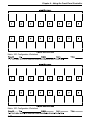
RGB Input Connections with Right & Left Audio
AV SOURCE UNIT
AUDIO
OUTPUT
VIDEO OUTPUT
L R
R G B
IN P U TS
IN P U TS
RED
G RE EN
( SYNC)
IN P U TS
IN P U TS
IN P U TS
INP UTS
INP UTS
SYNC/
VIDEO
SYNC/
VIDEO
BL UE
IN P U TS
OU TPU TS
OU TPU TS
THIS SWITCHER IS CONFIGURED FOR 8 X 8 RGBS,
8 X 8 COMPOSITE VIDEO, AND 8 X 8 AUDIO.
R G B
VIDEO INPUT
VIDEO DESTINATION UNIT
AUDIO DESTINATION UNIT
_______ Audio Connections may or may not be used. See page 3-9 for wiring.
3-3
Extron • Matrix 200 • User’s Manual
Chapter 3 • Rear Panel Connections
RGBS Input Connections with Right & Left Audio
AV SOURCE UNIT
AUDIO
OUTPUT
VIDEO OUTPUT
L R
SYNC OUTPUT
R G B
IN P U TS
H&V
IN P U TS
RED
G RE EN
( SYNC)
IN P U TS
IN P U TS
IN P U TS
INP UTS
INP UTS
SYNC/
VIDEO
SYNC/
VIDEO
BL UE
IN P U TS
OU TPU TS
OU TPU TS
THIS SWITCHER IS CONFIGURED FO
8 X 8 COMPOSITE VIDEO, AND 8 X 8 A
R G B
H&V
VIDEO INPUT
SYNC INPUT
VIDEO DESTINATION UNIT
AUDIO DESTINATION UNIT
_______ Audio Connections may or may not be used. See page 3-9 for wiring.
Extron • Matrix 200 • User’s Manual
3-4
Chapter 3 • Rear Panel Connections
RGBHV Input Connections with Right & Left Audio
AV SOURCE UNIT
AUDIO
OUTPUT
VIDEO OUTPUT
L R
SYNC OUTPUT
R G B
IN P U TS
H
IN P U TS
RED
G RE EN
( SYNC)
IN P U TS
IN P U TS
V
IN P U TS
IN PU TS
IN P U TS
SYNC/
VIDEO
SYNC/
VIDEO
BL UE
IN P U TS
OU TPU TS
OU TPU TS
SWITCHER
IS CONFIGURED
THISTHIS
SWITCHER
IS CONFIGURED
FOR 8 FOR
X 8 RGBS,
8 X 8 COMPOSITE VIDEO, AND 8 X 8 AUDIO.
8 X 8 RGBHV, AND 8 X 8 AUDIO
R G B
H
VIDEO INPUT
V
SYNC INPUT
VIDEO DESTINATION UNIT
AUDIO DESTINATION UNIT
_______ Audio Connections may or may not be used. See page 3-9 for wiring.
3-5
Extron • Matrix 200 • User’s Manual
Chapter 3 • Rear Panel Connections
Composite Video Input Connections
NTSC and PAL are television or VCR type signals on a single coax cable,
which may or may not have stereo audio. For this application, the Matrix 200
uses one Composite Video module, shown below in the right-most position.
Possible uses include: NTSC or PAL, with or without right & left audio follow.
Connect the output of an NTSC/PAL video source to a Video module input.
(See illustration below.) Connect the video output from the Matrix to a
destination device that uses Composite Video.
_______ NTSC - National Television Standards Committee
PAL - Phase Alternation Line
Composite Video Input with Right & Left Audio
AV SOURCE UNIT
AUDIO
OUTPUT
L R
VIDEO OUTPUT
I N P U TS
RED
I N P U TS
I N P U TS
G RE E N
( SY NC)
I N P U TS
I N P U TS
INP UT S
INP UT S
S Y NC/
V I DE O
S Y NC/
V I DE O
B L UE
I N P U TS
OU TPU TS
OU TPU TS
THIS SWITCHER IS CONFIGURED FOR 8 X 8 RGBS,
8 X 8 COMPOSITE VIDEO, AND 8 X 8 AUDIO.
VIDEO INPUT
VIDEO DESTINATION UNIT
AUDIO DESTINATION UNIT
_______ Audio Connections may or may not be used. See page 3-9 for wiring.
Extron • Matrix 200 • User’s Manual
3-6
Chapter 3 • Rear Panel Connections
S-Video Input Connections
S-Video (S-VHS) is typically the output from the AV source on a 4-pin miniature
din-type connector and must be converted to 2 BNC type connectors - one for
Chroma (C) and the other for Luminance (Y).
_______ For S-VHS to BNC interface, use Extron cable 26-353-01.
To connect S-Video to the Matrix 200, the Matrix must be ordered with two
composite video modules. Use one for Luminance (Y) and the other for Chroma
(C). The Y and C signal lines are then connected to the two video modules. See
illustration on facing page.
_______ When connecting Y and C cables, be sure to use the same input numbers on the
two video modules for each source. This example uses number 1 inputs. Also,
use the same output number pair for each destination. This example uses
number 1 outputs, but we could have used outputs number 2, or 3, etc.
Input Connections
Choose which input number to use to connect the S-Video source device to the
Matrix 200. Connect the Luminance (Y) to the input connector on the first (left)
Video module and the Chroma (C) to the same input number on the second
(right) Video module.
If audio is used, connect the right and left audio source outputs to the right and
left inputs on the back of the Matrix. See page 3-9 for details on audio
connections.
Output Connections
Choose which Matrix 200 output number to use for the S-Video destination unit.
Connect the Luminance (Y) output from the first (left) Video module to the
Luminance input of the destination unit. Connect the Chroma (C) from the same
output number on the second (right) Video module to the Chroma input of the
Video destination unit.
If audio is used, connect the right and left audio output from the Matrix connector
to the right and left inputs of the audio destination unit. See page 3-9 for details
on audio connections.
_______ A Matrix 200 can be configured with RGsB (sync on green) and S-Video.
3-7
Extron • Matrix 200 • User’s Manual
Chapter 3 • Rear Panel Connections
S-Video Input Connections with Right & Left Audio
AUDIO
OUTPUT
AV
SOURCE
UNIT
L R
S-VIDEO OUTPUT
Y
C
Extron p/n 26-353-01
LUMINANCE (Y)
IN P U TS
RED
IN P U TS
IN P U TS
G REEN
(SYNC)
IN P U TS
CHROMA (C)
IN P U TS
IN PU TS
IN P U TS
SYNC/
VIDEO
SYNC/
VIDEO
BLUE
IN P U TS
OU TPU TS
OU TPU TS
THIS SWITCHER IS CONFIGURED FOR 8 X 8 RGB,
8 X 8 S-VIDEO, AND 8 X 8 AUDIO.
VIDEO
DESTINATION
UNIT
Y
LUMINANCE
INPUT
C
CHROMA
INPUT
AUDIO DESTINATION UNIT
_______ Audio Connections may or may not be used. See page 3-9 for wiring.
Extron • Matrix 200 • User’s Manual
3-8
Chapter 3 • Rear Panel Connections
Audio Terminal Connections
The rear of the Matrix 200 has two rows (16 sets) of audio connector pins below
the BNC connectors. The top row is for 8 inputs and the bottom row for 8
outputs. Each group of six pins accommodates a left and a right audio channel.
One sample is shown here.
The 6-terminal screw (Phoenix®) connectors are supplied with the switcher. The
connectors are wired to the audio cables using the captive screws inside the
connectors. The connectors are then plugged into the appropriate position in the
audio terminal strip on the rear panel. The audio area of the back panel is
labeled “R” (right) and “L” (left) for each channel.
When wiring the connectors and inserting them into the Matrix 200
switcher, the screw heads (see picture right) must face down.
Audio Wiring Applications
Three methods of wiring the connectors for input and output are listed here and
illustrated below. The connector screws do not show in the picture because they
are on the other side.
· Unbalanced High Impedance (High Z) Stereo Tip, Ring, Ground (Left & Right)
· Balanced High Impedance (High Z) Stereo Tip, Ring (Left & Right)
· Balanced 600 ohms input Impedance Stereo Tip, Ring (Left & Right)
TIP +
RING
The audio cable
equivalent connections
are shown here.
-
TIP RING
TIP
SLEEVE
SLEEVE
SLEEVE
_______ If using unbalanced audio output, use the lower-left connector as an example
and connect the sleeve to Gnd. Connecting it to the negative (-) terminal will
damage audio output circuits.
_______ Use Phoenix® audio connectors, Extron part number 10-163-01
3-9
Extron • Matrix 200 • User’s Manual
Matrix 200
User’s Manual
4
Chapter Four
Using the Front Panel Controller
Power On Message
Using the LCD Display
Tie (default) Menus
Selecting Menus with the Keypad
Automating the Matrix 200
QuickSwitch Front Panel Controller
Chapter 4 • Using the Front Panel Controller
Front Panel Controller (FPC) Operation
Control/Indicator
Function
LCD display
The Liquid Crystal Display (LCD) has two-rows and 16-columns of
character positions. It displays the Matrix status, as well as menus used
to configure the unit.
Cursor keys
Press Left/Right keys to step to the next accessible position. (Cursor
skips over positions that cannot be accessed.) Press Up/Down keys to
step through choices.
RGBS key/light (*)
Press to select all RGB and Sync modules as a Gang. The light is on
when the mode is selected. Press again to deselect.
Audio key/light (*)
Press to select audio connections. Left and right audio channels cannot
be separated. Light is on when the mode is selected. Press again to
deselect.
Video key/light (*)
Press to select all video connections as a Gang. This could be
Composite Video or S-Video. Light is on when selected. Press again to
deselect.
(*) Pressing any combination of these three keys will put them together as a “Group”;
pressing a key again will remove that Gang from the Group.
RGBS Mute key/light Press to mute all RGB and Sync outputs. Light is on when muted. Press
again to restore muted outputs.
Audio Mute key/light Press to mute all audio outputs. Light is on to indicate mute mode
selected. Press again to restore audio outputs.
4-1
Menu key/light
Press for Selection Menu, from which other menu selections can be
made. The last menu selected will be “remembered” the next time this
key is pressed.
Keypad
Dual function 12-key pad (0-9, #, *) is used to enter numeric data into
SmartControl configuration memory as well as to select menus (next
page).
Power key/light
Press to turn power on; press again to turn it off. Light is on when power
is on.
Break Away LED
When lit, the information displayed in the LCD does not represent a
group or a gang, but an individual plane or all planes in a group that are
not tied together.
Extron • Matrix 200 • User’s Manual
Chapter 4 • Using the Front Panel Controller
Enter key/light
Press to accept or store the current display changes. The light blinks when
pressed.
Escape key
Press to cancel current operation or to return to default (TIE) menu.
Selecting Menus Using the SmartControl™ Keypad
First press Menu, and then press one of the following:
[Escape] to select the default Tie (Connection) Menu
[1]
[2]
[3]
to select Copy menu. (copy a configuration)
to select RGB Sync Delay menu.
to select Mute menu.
[4]
[5]
[6]
to select Preset menu. (save/load a preset)
to select Sequence menu.
to select Program menu.
[7]
[8]
[9]
to select Function menu.
to select Security menu.
to select Miscellaneous menu.
[0]
to select the Configure Audio menu
The Matrix 200 has 10 user-selectable menus, each of which is discussed
separately in the paragraphs that follow.
Power On Message
Press the Power key to apply power to the Matrix 200. The following
identification message will display for five seconds. SmartControl detects the I/O
module configuration and displays the information. Letters on the second line of
the display show what type of switchers or planes are installed in the six (6)
available Matrix 200 positions.
The example here indicates the following configuration:
R -Plane 1 has an HRAM module for Red
G -Plane 2 has an HRAM module for Green
B -Plane 3 has an HRAM module for Blue
H -Plane 4 has a Sync module for Horizontal
V -Plane 5 has a Sync module for Vertical
A -Plane 6 has an Audio module
_ -Plane 7 is always empty
other possibilities include:
C -Composite Video module (Plane 4 and/or 5)
S -One Sync module detected, indicating composite H/V (Plane 4)
After five seconds, the LCD will display one of three Tie Menus. This menu,
called the “default menu”, displays input/output. It is explained later in this
chapter.
The example here shows a Group with input #3 Tied to outputs #1 and #2. Input
#2 is Tied to output # 4. Details follow.
The plane number refers to the physical address of the I/O module.
Extron • Matrix 200 • User’s Manual
4-2
Chapter 4 • Using the Front Panel Controller
Tie Menu (default menu)
The Tie Menu is the default menu for the Matrix 200. Used to make all input/
output connections, this menu has four submenus (Tie levels): Tie Gang, Tie All,
Tie Group, and the Tie Individual Menus. See examples on the next page.
How to select the Default Menu. This menu is displayed automatically
(immediately after the Power On message) when the Matrix 200 is powered on.
The Default menu may be selected at any time during normal operation by
pressing Escape.
Using the LCD Display
In the illustration below, the numbers 1 thru 8 in the top row are fixed output
numbers. The space below each output position will contain the number of the
input to be tied (connected) to that output. These numbers can vary from 1
through 8, depending on how the Matrix 200 is configured. The example here
shows input #3 tied to output #1 with no inputs tied to the other seven outputs.
Throughout this section, references are made to
the positions in the LCD display:
•
•
The top row is zero (0), and the bottom row
is one (1).
The left-most position is zero (0), and the
right-most is 15.
The picture above shows some position numbers. For example, the upper left
position is 0,0. The cursor (indicated by the underline character “_”) is at 0,3.
_______ The symbol > is used in many of the Matrix 200 menus as a cursor point from
which the function to the right may be changed.
4-3
Extron • Matrix 200 • User’s Manual
Chapter 4 • Using the Front Panel Controller
How I/O Modules Are Handled
Each Matrix 200 is custom designed, therefore, there could be different
combinations of I/O modules consisting of RGB, Sync, Video and/or Audio
modules. Each I/O module occupies a separate plane and can be handled in any
of four ways. The LCD displays below show four examples of submenu Tie
Levels. These will be explained in detail later in this chapter.
1. The first Tie Level ties “All” modules together. This includes each I/O module,
regardless of any other Gang or Group assignment.
2. The second Tie Level display shows RGB, however, if the Matrix has Sync
modules, they are included. The Matrix 200 recognizes the I/O modules
installed and automatically “Gangs” associated modules together. There are
three categories for ganging and these are related to the three front panel
keys shown below.
· The RGBS Gang includes all HRAM and Sync modules installed.
(RGB, RGBS or RGBHV)
· The Audio Gang is the stereo Audio module.
(Left and right channels cannot be separated.)
· The Video Gang includes all Video modules.
(Composite or S-Video)
3. Another way is to combine any of the three Gangs (previously mentioned).
When TIE>RGB appears in the display, pressing combinations of these three
keys will put them together as a Group, and the display changes to TIE>GRP.
4. Any I/O module can be handled separately. This is called “Individual” or
“Breakaway” mode. A typical Tie Individual Submenu is shown here.
For a Matrix with RGBS, Composite Video and Audio, other selections
include: Grn, Blu, Syn, Cv2 and Aud.
_______ Some Useful Terms
Matrix Switching – Matrix switching differs from ordinary switching in that instead of one input being tied
(connected) one output, an input can be tied to more than one output at the same time.
Tie – A connection between an Input and an Output.
Set of Ties – Connections between one Input and more than one Output.
Configuration – Any Tie, Set of Ties, or Sets of Ties between Input(s) and Output(s).
Active Configuration – The configuration that is currently being used by the Matrix 200 .
Preset – A configuration that has been stored and can be recalled and used again.
Extron • Matrix 200 • User’s Manual
4-4
Chapter 4 • Using the Front Panel Controller
Changing Tie Submenus
Many of the menus have submenus. To change Tie level, use the Left/Right
cursor keys to place the cursor at (0,3) under the >. Use the Up/Down cursor
keys to display the desired level.
The choices that appear will depend on how the Matrix is configured. For
example, if a Matrix has RGBS, Composite Video and Audio, the Tie Menu
choices will be: ALL, RGB, Red, Grn, Blu, Syn, Cv2 and Aud.
The cursor is a blinking line under the position where changes can be
made. The Left/Right cursor movement steps only to those positions
that can be accessed.
Tie All Level
In the Tie All menu, connections to all I/O ports (RGB, VID, and AUD) are made
simultaneously.
1. If not presently in the (default) Tie Menu, press the Escape key. Observe that
the cursor is at the 0,3 position, as in the figure above.
2. If not already displayed, use the Up/Down cursor control keys until the word
“ALL” is displayed to the right of the cursor.
_______ A blinking period (“.”) in any position of the lower row of the LCD display
indicates that this output connection is different on each plane (Breakaway).
3. Use the Left/Right cursor keys to move the cursor under the first input/output
connection to be connected. For example, to connect input 3 to output 1,
place the cursor under the “0” in the bottom row, under output #1 (position
1,8).
4. With the cursor positioned under the input/output position, do either one of the
following:
Use the Up/Down cursor keys to step to “3”,
or
Press the “3” key on the numeric keypad.
Observe that the “3” in the bottom row is blinking to signify a “tentative”
connection, meaning that the connection has not yet been stored in memory.
(See menu at top of page.)
5. Move the cursor under the next input/output connection to be made and enter
the desired input number. Continue doing this until all tentative input/output
connections have been made. Observe that all input/output connections to be
changed are now blinking. (Those that are not to be changed will not blink.)
6. Press Enter to store the input/output connections into memory.
4-5
Extron • Matrix 200 • User’s Manual
Chapter 4 • Using the Front Panel Controller
Tie Group Level
The Matrix 200 has three I/O Gangs: RGBS, Video and Audio. The Tie Group
Level allows one or more Gangs to be configured as a Group. On the FPC, each
of these three Gangs has a button. In the LCD display, the Gang names are
abbreviated as: RGB, VID, and AUD. Use the steps below to set up a group.
For this example, combine RGB with Audio and set them up as a Group.
1. Press Escape to display the default Tie Menu (if not already displayed).
Observe that the cursor is at the 0,3 position.
2. If necessary, use the Up/Down cursor control keys to display “RGB” to the
right of the cursor (as pictured above). RGB is a group by itself, but, for this
example, add Audio.
3. On the FPC, press RGBS, and then AUDIO. Observe that the LED indicators
at the center of both the RGB and AUDIO buttons are lit, indicating that the
corresponding functions have been selected.
_______ If the Matrix is not configured for a particular function (for example, no Audio),
the LED in the center of the button will not light.
4. The LCD display should now show GRP, instead of RGB. This means that
more than one Gang has been selected. See figure below. For this example,
connect input 4 (consisting of RGB and Audio) to output 1.
5. Use the Left/Right keys to position the cursor under the first input/output
connection to be switched. In this example, under the “0” below output #1.
6. Move the cursor to the first input/output position (INP #1). Use the Up/Down
cursor keys to step to “4” in the lower row. (Or press the “4” key on the
numeric keypad.) See picture.
Observe that the “4” is blinking to signify a “tentative” connection. That is, the
connection has not yet been stored in memory.
7. Move the cursor to the next input/output connection to be made and enter the
desired input number. Continue until all input/output selections have been
made. Observe that all input/output connections to be changed should now be
blinking to show tentative connections (the changes have not yet been
stored). Those positions that have not been altered will not blink.
8. When all input/output connections have been made, press Enter to store the
input/output connection settings.
Extron • Matrix 200 • User’s Manual
4-6
Chapter 4 • Using the Front Panel Controller
Tie Individual Level (Breakaway)
With this menu, connections are made separately to each of the I/O ports. For
this example, connect Red input #5 to outputs #1 and #3. The actual display
information may vary, depending on the Matrix configuration.
1. If not already in the default Tie Menu, select it by pressing Escape. Observe
that the cursor is at the 0,3 position (under the >).
2. Use the Up/Down cursor keys to step through the choices. (e.g. Red, Grn, Blu,
Syn/Cv1, Cv2, Au1, etc.). Stop when your choice (Red for this example)
appears.
3. Use the Left/Right keys to position the cursor under the first input/output
position to be connected (INP #1).
4. With the cursor positioned under INP position #1, use the Up/Down cursor
keys to step to “5”, or press the “5” key on the numeric keypad. Observe that
the “5” in the bottom row is blinking to signify a “tentative” connection,
meaning it has not yet been stored in memory.
5. Continue by moving the cursor under the next input/output connection to be
made (INP position #3) and enter the input number (5). Repeat this step for
each connection to be made. Observe that all INP positions that have
tentative changes are now blinking. (Those input/output connections that are
not to be changed will not blink.)
6. When all input/output connections have been entered, use the Left/Right
cursor keys to move the cursor at position 0,3. Press Enter to store the input/
output connection settings in memory.
At this point, the Breakaway indicator will light to indicate that the connections
were made on an Individual plane and not on a Gang.
_______ After setting up an individual configuration, it can be copied to other planes. For
example, the configuration made for Red can be copied to Green and Blue. This
is explained later in this chapter.
Menu Selection
Press the Menu key, and observe the LCD display (see picture). This menu
allows the user to select the particular menu that pertains to the function to be
performed. The LCD displays the menu number and name (1. Copy). Notice that
the numeric keypad has the corresponding menu name next to each number
key.
Notice that the cursor is in the second line, first position (1,0), under the menu
number (1). To select this menu, press Enter. To select another menu, press the
corresponding numeric key. This is the fastest way. When selecting with the
keypad, it is not necessary to press Enter.
4-7
Extron • Matrix 200 • User’s Manual
Chapter 4 • Using the Front Panel Controller
Another way to choose a menu is to use the Up/Down buttons to step through
the list of menus, and then press Enter when the desired menu appears.
The last menu# used is stored. For example, if menu 3 was used last, the next
time the menu button is pressed, menu 3 appears in the display. To select it
again, the steps are Menu, followed by Enter.
e.g. The fastest way to select a menu, when the Matrix 200 is in the default menu,
is to press Menu followed by the number key for the desired menu. See keypad
picture.
Using the Copy Menu (1)
This menu is used to copy settings from one Plane, or module, to another. This
is especially useful when the system is completely broken away, since it
eliminates the need to set up different Planes with similar programs. For
example, after doing a “Tie Individual” for the Red Plane, as described earlier in
this chapter, that program for the Red Plane can now be copied to the Green and
Blue Planes, etc. This eliminates having to do the same program more than
once.
Making Changes
1. Copy from - Use Left/Right keys to move the cursor at position 0,5 (under the
> in the top line). Use Up/Down keys to step through available Planes (I/O
modules) until the desired source name is displayed. The example shows
Red.
2. Copy to - Use the Left/Right keys to move the cursor to position 1,6 (under the
> in the bottom line). Use Up/Down keys to step through the available Planes
until the destination (copy to) name is displayed. The example shows Grn.
3. Press Enter to accept the copy source and destination, and execute the copy.
4. Repeat steps 1 thru 3 for any other modules you wish to copy. For example,
copy the Red Plane to Green Plane, and then to the Blue Plane, etc.
5. Press Escape to return to the default menu.
Using the RGB Sync Delay Menu (2)
This menu programs the Matrix 200 for “glitch-free” switching of Sync and RGB
signals by establishing a fixed time delay between them. A time delay can be set
for each output. When switching takes place, the Sync connects to the output
right away, but the RGB signals connect after the time delay. This means the
projector is already in sync when the picture arrives. The sync delay range is
from 0 to 9.9 seconds, in increments of 0.1 seconds.
To select this menu, press Menu, followed by “2”, or use the Menu Selection
procedure on page 4-6.
_______ The “1” shown in the picture will be the number 1 to 8 of the output sync to be
affected, (this number is 1 to 4 for 4 x 4 or 8 x 4 switchers) or “All” to delay
switching all outputs by the same amount.
Extron • Matrix 200 • User’s Manual
4-8
Chapter 4 • Using the Front Panel Controller
1. With the Delay RGB->Sync menu displayed, the cursor should be at 1,0. Use
the Up/Down cursor keys to select All, Out1, Out2, etc., for a specific output.
2. Use the cursor keys to position the cursor at position 1,11. Use the Up/Down
cursor keys to sequence through the available delay times in increments of 1
second (0 thru 9) until the desired delay time is displayed.
(If required, step to position 1,13 and set a value for “tenths” of a second.)
3. Press Enter to store the sync delay value.
4. Press Menu to continue setup, or press Escape to return to the default menu.
Mute Output Menu (3)
This menu allows selective muting of individual outputs from the Matrix 200.
There are three choices for muting selective outputs: RGB, AUD and ALL,
where ALL includes RGB and AUD. If the Matrix does not have audio, that will
not display as a choice.
To select the Mute Menu, press Menu, followed by “3” on the numeric pad.
To change the Mute Output Settings, do the following:
1. With the Mute menu displayed, and the cursor under the >, use the Up/Down
keys to select the function to be changed (RGB, AUD or ALL).
2. Use the Right/Left keys to move the cursor to the output to be muted.
3. Use the Up/Down keys to switch between Y (yes) and N (no).
Repeat steps 2 and 3 until all choices have been made.
4. Press Enter to save the setup.
5. Press Escape to return to default menu.
4-9
Extron • Matrix 200 • User’s Manual
Chapter 4 • Using the Front Panel Controller
Automating the Matrix 200
The three stages of automating the Matrix 200 switching are “presets”,
“sequences” and “programs”. The three menus that follow are associated with
automating:
• Routing configurations may be stored as Presets. (See Menu 4.)
• These stored Presets may be assigned as timed steps, to run in a Sequence.
(See Menu 5.)
A Sequence may be started at any time, and will loop through preset steps until
stopped.
• A Preset, or a Sequence, may also be Programmed to start at a specific time on
a specific date. (See Menu 6.)
Preset Menus (4)
A “Preset” is any routing configuration that has been set up in the Matrix 200 and
has been stored for future use. Any time the Matrix 200 has been configured, it
may be desirable to save those settings and use them again. Use the “Save
Conn. As Preset” menu to save the current routing configuration to SmartControl
memory by assigning it a number (1 - 20).
Later, when a Preset (a previously stored configuration) is needed, use the “Load
Preset” menu to set the Matrix for those conditions. The sections on Menus 5
and 6 explain how to use these Presets.
Caution: Saving a preset will overwrite any previous routing information saved under the same
preset number.
To select the Preset Menu, press Menu, followed by “4” on the numeric pad.
Load a Previously Saved Preset (menu 4)
1. With the Preset menu displayed, and the cursor under the “P”, use the Up/
Down cursor keys to display LOAD on the top row.
2. Use the cursor keys to move the cursor to the lower right corner of the
display (position 1,15). Use the keypad to enter the desired preset number
(1 - 20).
3. Press Enter to load that preset number. If there is nothing stored in the preset
location requested, a display of “Invalid Preset” will appear.
4. Press Escape to return to the default menu.
Hint 1: Make a list of all routing connections that have been saved as presets. List them by preset
number with a description to ensure that the correct preset is selected for each
application.
Hint 2: Before making a completely new preset configuration, load one that closely fits your new
requirements. Modify it, and save it under a new preset number.
Extron • Matrix 200 • User’s Manual
4-10
Chapter 4 • Using the Front Panel Controller
Save the Current Routing as a Preset (menu 4)
1. With the Preset menu displayed and the cursor under the “P”, use the Up/
Down cursor keys to display the SAVE menu, as shown here. The Preset
number should be blinking.
2. Use the cursor keys to move the cursor to the lower right corner of the display
(last position 1,15). Use the keypad to enter the preset number (1 - 20).
3. Press Enter to store the current routing configuration to memory.
4. Press Escape to return to default menu.
_______ The following menus (5 and 6) explain how use the Presets to automate the
Matrix 200.
Sequence Menu (5)
Creating a Sequence is the second step in automating the Matrix 200. Menu 4
was used to save preset configurations. Menu 5, called “Sequence menu”, uses
those presets to automate applications for the Matrix 200.
A timing sequence can be written to have up to 31 steps. Each step loads a
preset configuration (created by Menu 4) to be active for a specific period of
time. At the end of that time period, another preset loads a configuration for
another time period, etc. Without intervention, a sequence will loop. That is, after
the last step of a sequence ends (times out), the first step begins and the
sequence repeats until stopped. The Matrix 200 can store up to 31 separate
sequences; each sequence can consist of up to 31 steps.
There are three sequencing submenus:
• Edit (ED) Submenu
• Copy Submenu
• Operation Submenu
The Operation Submenu is divided into four functions to manually control the
sequence. These are: Start, Stop, Resume, and Delete.
To select the Sequence Menu, press Menu, followed by “5” on the numeric pad.
4-11
Extron • Matrix 200 • User’s Manual
Chapter 4 • Using the Front Panel Controller
Create a Timing Sequence (menu 5)
1. To create a timing sequence, place the cursor at the upper left corner of
the LCD display (position 0,0), then use the Up/Down keys to select the
Edit (ED) Submenu, shown here. Observe that the first step of the
sequence (01) is displayed at the far right end of the top row.
2. Move the cursor to position 1,5 and enter the preset number (1-20) to be used
in this step of the sequence. (Only saved presets may be used.)
3. Move the cursor to the appropriate time digits (shown as hh:mm:ss) and enter
the time duration for this sequence step. (Use the 24-hour clock.) Numbers
can be entered directly from the keypad or by scrolling with the Up/Down
keys.
_______ The maximum time duration is 16:59:59.
4. Move the cursor to the top, right position (0,15) and change the number (Up
key) for the next step in the sequence. Repeat 2 and 3 to set the preset
number (1-20) and the time duration for the next step of this sequence.
Repeat this for each step in the sequence.
5. Repeat 2 thru 4, above, until all steps of the sequence have been set.
6. When finished, press Enter to store the sequence.
Edit a Timing Sequence (menu 5)
To edit a sequence, place the cursor at position 0,7 and enter the number of the
sequence to be edited. Repeat steps 2 - 6 (above) to make changes until the
sequence is correct.
To delete a step (for example, delete step 03) from a sequence, load the
sequence and scroll to the step to be deleted (03). Press Delete (the # key). The
steps that followed step 03 will move forward. Step 04 now becomes Step 03,
etc.
To insert a new step in a sequence, display the SQ:ED menu, shown above.
For this example, we will insert a new step before step 4, of sequence 2. The
new step will use preset 6 for a duration of 12 minutes.
1. Choose the number of the sequence to be altered (02).
2. Use the cursor keys to display the number of the step where the new step will
be inserted (04).
3. Press Insert (the * key).
4. Move the cursor to position 1,4/5 and enter the preset number to be used (06).
5. Move the cursor to the minutes position (mm) and enter the time (12).
6. When finished, press Enter to store the new step.
Extron • Matrix 200 • User’s Manual
4-12
Chapter 4 • Using the Front Panel Controller
Copying a Sequence (menu 5)
When creating a new sequence, it may be easier to make a copy of an existing
sequence and then edit the copy. The new, edited copy will be assigned a new
sequence number. To make a copy of an existing sequence, do the following:
1. With the cursor at the upper left corner of the LCD display (position 0,0), use
the Up/Down keys to select the Copy Submenu. Observe that sequence “01”
is displayed in the top row, and a “To” sequence number is in the lower right.
_______ This example copies Seq 01 to Seq 02.
2. To change either of these sequence numbers, use the Left/Right keys to step
to the location of the number(s) to be changed.
3. At the top-right, enter the number (01-32) of the sequence to copy using the
keys of the numeric keypad.
4. Move the cursor to the bottom row of the LCD display (positions 1,13-14) and
enter the sequence number (1-32) assigned to the new copy.
5. Press Enter to make the copy.
_______ The two sequences (01 & 02) are now identical. Use the Sequence Edit menu to
make changes to the new sequence.
Start a Sequence (menu 5)
1. To start a sequence, place the cursor at the upper left corner of the LCD
display (position 0,0). Use the Up/Down keys to select the Operation
Submenu. (See picture.)
2. With the cursor at the 1,9 position, use the Up/Down cursor keys to scroll
through the menu choices until “START” appears in the LCD display.
3. Use the Left/Right keys to step the cursor to the SEQ position and enter the
number of the sequence to be started.
4. Press Enter to start the sequence.
_______ The sequence will continue running in a loop (repeat) until it is stopped.
The Start Menu is replaced by a Stop Menu. Only one sequence can run at a
time.
Stop the Sequence (menu 5)
When a sequence is running, the “Enter To Stop” menu (left) appears in place
of the Operation Menu. Press Enter to stop the sequence that is running. The
Stop Menu is now replaced by the Operation Start menu.
4-13
Extron • Matrix 200 • User’s Manual
Chapter 4 • Using the Front Panel Controller
Resume the Sequence (menu 5)
After a sequence has been stopped, SmartControl remembers which sequence
was running. To resume the stopped sequence, select the Operation Submenu
and place the cursor under the >. Use the Up/Down keys to display “Resume”.
Press Enter to resume running the sequence that was stopped. There is no
sequence number required; it can only resume the sequence that was last
running.
Delete a Sequence (menu 5)
1. To delete a sequence, place the cursor at the upper left hand corner of
the LCD display (position 0,0), then use the Up/Down keys to select the
Operation Submenu, see picture.
2. With the cursor at the 1,9 position, use the Up/Down cursor keys to
scroll through the menu choices until “DELETE” is displayed (where Start
is shown in the picture).
3. Move the cursor to the SEQ position and enter the number of the
sequence to be deleted.
4. Press Enter to delete the sequence.
Program Menus (6)
The Program Menus are the third step in automating the Matrix 200. (Previous
menus, 1-5, must be used to prepare for the use of this menu.) This feature is
especially convenient for video post-production and program distribution where
full switching automation is desired.
In the Matrix 200, a Program uses the built-in clock and calendar to load a readymade Sequence (see menu 5) or a Preset (see menu 4) at a specific date and
time.
_______ Only one program can exist at one time.
For example, Sequence 02 may consist of the following steps:
Step 01, load preset 1 to run for 10 minutes.
Step 02, load preset 5 to run for 25 minutes.
Step 03, load preset 7 for 45 minutes.
When a Sequence is loaded, it will loop (repeat) until it is stopped.
To select the Program (PG) menu press Menu, followed by “6”. Observe that the
Program menu is displayed. The three Program menus are described on the
following page.
In the following example, program the Matrix 200 to load Sequence 02 on 31
October, 1997 (31/10/97), at 3:15 p.m. (15:15:00).
_______ 1. Both date and time must be set for a program to run; neither entry can be
skipped.
2. Using an old date will give an invalid date error.
Extron • Matrix 200 • User’s Manual
4-14
Chapter 4 • Using the Front Panel Controller
Program Start Time/Date (menu 6)
The Program menu to the left has 7 selection points. Use the Left/Right cursor
keys to step from one to another. Three selection points are indicated by the
character ">". These are used to define the type of Program menu. The other
four selection points are for entering data.
1. To program a sequence (or a preset) start date/time, place the cursor at
position 0,2 (PG>)and use the Up/Down keys to select the Start Day menu
shown here.
2. Press the Right cursor key to step the cursor to the 0,9 position. Use the Up/
Down cursor keys to select which is to be programmed: SEQ (Sequence) or
PRE (Preset).
3. Press the Right key again to step to position 0,13 and use the Up/Down keys
to select the desired Preset (or Sequence) number. (Where picture shows
01.)
4. Step the cursor to position 1,2, and use the Up/Down keys to select “DAY”.
5. Use the Left/Right buttons to move the cursor through the positions to be
changed (1,8 - 1,15). Use the numeric keypad to enter the numbers for the
day (dy), month (mo), and year (yr) for the desired start date. For example, 31
October, 1997 should become 31/10/97.
6. Repeat the above steps 3 and 4. This time select the “TIME” menu, and enter
the start time at positions 1,8 - 1,15. Use the keypad keys to enter hour (hh),
minute (mm), and second (ss) for the desired start time. For example, 3:15
p.m. is 15:15:00.
_______ When entering a 2-digit number from the keypad, it is not necessary to move the
cursor for each digit. The SmartControl enters the first number in the left position
and the second number to the right. For example, to enter 15 minutes, put the
cursor at “mm” and press “1”, and then “5”.
7. Press Enter to store the program.
Program Delete (menu 6)
There can be only one program in the Matrix 200 at one time. To delete the
program, move the cursor at position 0,2 in the Program Menu and use the Up/
Down keys to display the Delete Menu. See illustration at left.
Press Enter to delete the program.
4-15
Extron • Matrix 200 • User’s Manual
Chapter 4 • Using the Front Panel Controller
Function Menu (7)
This menu provides access to different operational functions of the Matrix 200. It
has three submenus:
LED/LCD Contrast Submenu.
Tie Level Access Submenu.
Vertical Interval Switching Submenu.
To select this menu, press Menu, followed by “7”.
Selecting Function Submenus
With the Function Menu displayed, use the cursor keys to position the cursor at
position 0,0. Use the Up/Down cursor keys to sequence through the three
submenus (LCD/LED CTL, VERT INT, TIE LEVEL) until the desired submenu is
displayed.
Tie Level Access Submenu (menu 7)
This submenu determines the state transitions in the Tie Menu.
There are three choices:
• The “ALL” level affects connections at all switching levels (planes).
• The “RGB, AUD, VID” level affects connections only for the predefined
“gangs” of switching levels (planes). These gangs are related to the three
keys on the Front Panel.
• The “INDIVIDUAL” level permits independent changes to each level (plane).
1. With the Tie Level Submenu displayed, and the cursor at position 1,4, use the
Up/Down cursor keys to sequence between the three tie levels (ALL, RGB,
AUD, VID or INDIVIDUAL) until the desired tie level is displayed.
2. Press the Enter key to save tie level to SmartControl memory.
3. Press the Escape key to return to the default menu.
Vertical Interval Switching Submenu (menu 7)
This menu allows the Vertical Interval switching to be enabled or disabled. When
Enabled, Matrix switching is done using only the vertical sync of the input signal
of the Video Genlock connector at the rear of the Matrix 200. (See picture below,
right.) When Disabled, switching takes place immediately, independent of the
Video Genlock signal. If Enabled, and there is no Genlock input, switching will
take place after a slight delay.
1. With the Vertical Interval Submenu displayed and the cursor at position 1,8,
use the Up/Down cursor keys to toggle between Enable
and Disable, and display the desired mode.
REDUNDANT POWER
2. Press the Enter key to save the mode to SmartControl
memory.
!
1
DISCONNEC
3. Press the Escape key to return to default menu.
Extron • Matrix 200 • User’s Manual
4-16
Chapter 4 • Using the Front Panel Controller
Security Menu (8)
The Security Menu can place certain restrictions on the use of the Matrix 200.
The Executive Mode feature, when set to “ON”, will only allow the front panel
buttons to be used for viewing the Matrix 200 configuration, although ties can be
changed. If it is set to “OFF”, the front panel buttons can be used to change the
configuration of the Matrix 200.
The Security Lockout feature allows the Matrix 200 to be locked, protecting all
presets, sequences and programs from being changed. The Lockout feature
affects access both from the front panel controller (FPC), as well as from the RS232/RS-422 interface. (If the code is not known, see page 2-5 to permit access.)
To display the security menu, press Menu, followed by the numeric “8” key.
1. To set or change the security code, display the “Sec:Lock-Out Now” menu and
use the Up/Down keys to display the Set
Code menu (shown here).
(Press Escape at any time to exit this
menu.)
2. Use the cursor keys to step through the four digits and enter the current (....)
security code. Use the numeric keypad or the Up/Down cursor keys.
3. Press Enter. The menu changes, replacing the word “current” with “new”. Use
the numeric keypad or the Up/Down keys to enter the new security code.
4. Press Enter to store the new code.
To lock the FPC, display the “Sec:Lock-Out Now” menu and press Enter. If a
security code has not been set, the message “code not set” will display. If a
code has been set, the “Security Lockout” message will display.
_______ Once the Matrix is in this mode, any attempt to access the FPC will show only
this message. Access to the Matrix 200 is not allowed, either from the FPC or
from the RS-232/RS-422 interface.
To Unlock the FPC, use the cursor keys to step to the code positions (****) and
enter each digit from the numeric keypad. Press Enter to unlock the FPC and
display the “Sec:Lock-Out Now” menu. Once the Matrix is unlocked, it remains
unlocked until it is locked again, either by the FPC (Menu 8) or by the Host
system, through the RS-232/RS-422 interface.
4-17
Extron • Matrix 200 • User’s Manual
Chapter 4 • Using the Front Panel Controller
Miscellaneous Menu (9)
This menu is used to set the baud rate of the serial communications with the host
controller via the RS-232/RS-422 serial port. The menu can also display the
software version for the Main Controller and for the FPC. Provision for displaying
and setting the internal clock is also provided. The five Miscellaneous Submenus
are:
•
•
•
•
•
Show Local FPC Software Version
Show Main Controller Software Version.
Set Host Baud Rate
Show Time/Date
Set Time/Date
Descriptions follow.
To select this menu, press Menu, followed by “9”.
Selecting Submenus
With the Miscellaneous Menu displayed and the cursor at position 0,0, use the
Up/Down cursor keys to sequence through the five submenus until the desired
submenu is displayed.
Display FPC Software Version Submenu (menu 9)
This submenu is used to display the version number of the FPC software. This
is a view-only submenu; no user input is required. With the cursor at position
0,0, use the Up/Down cursor keys to display “LOCAL FPC” on the bottom row of
the display. Read software version at positions 1,12 thru 1,15.
Display Main Controller Software Version Submenu (menu 9)
This submenu is used to display the version number of the Main Controller
software. This is a view-only submenu; no user input is required. With the cursor
at position 0,0, use the Up/Down keys to display the menu shown here. The
software version is in the lower-right corner.
_______ The software version numbers for the FPC and the Main Controller board will not
necessarily be the same. They are updated separately.
Extron • Matrix 200 • User’s Manual
4-18
Chapter 4 • Using the Front Panel Controller
Host Baud Rate Submenu (menu 9)
This submenu displays the baud rate of the host controller: 9600 baud. This is a
fixed value and cannot be reset.
Show Clock Time & Date (menu 9)
With the cursor at position 0,0, use the Up/Down cursor keys to display “CLK:”
on the top row of the display. This submenu is used to display the date and time
of the internal clock. This is a view-only submenu; no user input is required.
Read clock date and time, as shown here.
Set Clock Time & Date (menu 9)
1. With the cursor at position 0,0 and the Clock Submenu displayed, use the Up/
Down cursor keys to display “SET”, as shown here.
2. Using the Left/Right cursor keys, position the cursor under the day (da) pair of
digits on the top row. Use either the Up/Down cursor keys or the keypad keys
to set the current day.
3. Using the Left/Right cursor keys to move the cursor and the Up/Down keys (or
keypad keys) to change the numbers, set the current month (mo) and year
(yr).
_______ When entering a 2-digit number from the keypad, it is not necessary to move the
cursor for each digit. The SmartControl enters the first number in the left position
and the second number to the right. For example, to enter 15 minutes, put the
cursor at “mm” and press “1”, and then “5”.
4. Use the same procedure to set the hour (hh), minutes (mm) and seconds (ss).
5. Return the cursor to the 0,0 position. Press the Enter key to save the setting
to memory.
4-19
Extron • Matrix 200 • User’s Manual
Chapter 4 • Using the Front Panel Controller
Configure Audio Menu (0)
The first time power is applied to the audio board, the following conditions exist:
No inputs are connected to outputs.
All inputs are set for professional levels.
All outputs are set for consumer levels.
Refer to the sample display screens on this page. The Configure Audio menu
allows audio plane(s) to be configured in the following ways:
Audio1 or 2 = which audio plane is to be configured
Audio plane #2 is not available as of this date.
INP or OUT = configuration is for an input or an output
1 thru 8 = which, of eight inputs or outputs, is to be configured
Lvl = CONSUMER or PROFESSIONAL means the level to be set is for
Consumer or Professional audio equipment
(Typical levels: Consumer audio ≈6v p-p; Professional audio ≈30v p-p)
When setting the Input (INP) gain:
>L, R, or LR = which stereo channel (left, right, or both) to be adjusted
+dB or - dB = set to “+” to increase the output level (gain);
set to “-” to decrease the output level (attenuate)
00dB = set the numeric value for dBs of gain (+) or attenuation (-).
The range is -95dB to +31dB.
When configuring Output (OUT):
Lvl = CONSUMER or PROFESSIONAL means the level to be set is for
Consumer or Professional audio equipment
__________ If using differential (or unbalanced) audio, see Audio Terminal Connections
section, page 3-9, to avoid possible damage to audio circuits.
Press Menu, followed by “0”, to display the Configure Audio Menu.
1. With the cursor at position 0,0 (under C), use the Up/Down keys to select input
(INP) or output (OUT) to be changed.
2. Use the Left/Right keys to step the cursor to each function to be changed.
(Input and output functions are explained above.)
3. With the cursor positioned, use the Up/Down keys to display choices.
(Numeric values can also be entered from the numeric keypad.)
4. When all configuration choices have been made, press Enter to store them.
Extron • Matrix 200 • User’s Manual
4-20
Chapter 4 • Using the Front Panel Controller
QuickSwitch™ Front Panel Controller (QS-FPC) Operation
The QuickSwitch Front Panel Controller (see below) has its controls arranged in
two areas. The left side is Input and Output buttons, and the right side is Control
buttons and I/O Module Select buttons.
The basic operation of this panel is that it allows the user to tie any one input to
one or more outputs. (An output can never be tied to more than one input.) Thus,
each input may have a tie (one output), or a “set of ties” (more than one output).
At any one time, the active configuration of a Matrix 200 may have a set of ties
per each available input. Any configuration (sets of ties) may be stored as a
Preset. The maximum number of Presets is eight. The Matrix 200 has Battery
Backup; Presets remain saved when power is off.
_______ Because each Matrix 200 is custom-built, it may have different combinations of
Input/Output (I/O) modules. For this reason, the operation of your unit will vary to
reflect these differences.
INPUTS
1
2
3
1
2
3
4
5
4
5
6
6
7
8
7
8
ENTER
PRESET
VIEW
RGBS
ESC
VIDEO
AUD 1
AUD 2
OUTPUTS
QS - FPC
MATRIX SWITCHER
Power On Switch and LED
Before using the Matrix 200 front panel, turn power
on with the Power Switch on the back of the unit
(shown right). The red LED on the left end of the front
panel (shown left) lights when power is on.
REDUNDANT POWER
!
FUSE: 250V ~0.8A TT
AC POWER INPUT
100-240V ~0.5A MAX 50/60 Hz
DISCONNECT ALL POWER CORDS BEFORE SERVICING
Input and Output Buttons
The panel has a button and an LED for each input and each output. If the matrix
is 4x4, only the four left input and output buttons and LEDs will operate. If the
matrix is 8x4, all eight input buttons will operate, but only the four left output
buttons and LEDs will operate. The best way to describe the Input and Output
buttons is to use them in real examples with the other panel buttons. This is done
on the pages that
follow.
_______ Each input button and
LED also refers to a
Preset number.
Presets are discussed
on the next page.
4-21
Extron • Matrix 200 • User’s Manual
Chapter 4 • Using the Front Panel Controller
I/O Module Select Buttons
The four buttons on the far right side of the panel are used to select the I/O
modules to be viewed or configured. The buttons and LEDs will not operate if the
corresponding modules are not installed in your Matrix 200. For example, if your
unit does not have audio, the AUD buttons and LEDs will not operate.
When an I/O button is pressed, the associated LED for that I/O module will light
to show that it is active. This “active” state remains in effect until that button is
pressed again and the LED goes out – or power is removed. These buttons may
be used independently or in combinations. For example, if you want to view or
configure both RGBS and Audio (audio follow), press RGBS and AUD 1.
RGBS Button – This button selects the I/O modules for Red, Green, Blue and Sync
modules to be viewed or configured. Here are some examples:
• If your unit has RGsB (no separate sync), the RGBS button operates on the Red,
Green and Blue signals.
• If your unit has RGB with composite sync, the button operates on the Red,
Green, Blue and Sync signals.
• If your unit has RGBH and V (separate sync), the button operates on the Red,
Green, Blue, Horizontal Sync and Vertical signals.
With RGBS active, switching configurations for RGB and Sync may be viewed or
set up by pressing Input and Output buttons. See example on the next page.
Video Button – If the matrix has Composite Video, or S-Video, press this button to
view or configure those signals.
AUD 1 Button – If the matrix has an audio module, this button allows Audio to be
configured or viewed.
AUD 2 Button – This button is reserved for future use.
Control Buttons
Enter Button – This button is used to save changes when setting up a
configuration. To set up a configuration, press the desired Input button, press the
desired Output button(s), and then press Enter. See examples on next page.
ESC Button – The Escape button is used to end an operation and reset all of panel
LEDs for Inputs, Outputs and Controls (active I/O Module LEDs remain on).
The ESC button does not reset any configurations that have been entered.
Preset – All current (active) configurations in the Matrix 200 may be stored as a
Preset. To do this, press Preset twice (or hold the button for two seconds) and
the Preset LED will blink. While the preset LED is blinking, press the Input button
for the Preset number to be stored. The LED for that Input will light briefly, and
then both the Input LED and the Preset LED will go out. (No output buttons will
light.) The Preset has now been stored. There can be one preset for each Input
button, for a total of eight – regardless of the number of available inputs or
outputs.
______ The Input buttons and LEDs have two independent functions – as Input numbers
and as Preset numbers. When using them to store or load a Preset, this has
nothing to do with which inputs are switched to which outputs.
To load a preset that has been stored, press Preset once (briefly). The LED will
light steady (not blinking). Press the Input button for the desired Preset number.
That LED will light briefly, and then both it and the Preset LED will go out.
With Presets stored, the Matrix 200 can be configured again without affecting the
stored Presets. This means that there can be eight matrix configurations stored
as Presets, and a ninth one active. However, when a Preset is loaded, it
destroys the active configuration.
Extron • Matrix 200 • User’s Manual
4-22
Chapter 4 • Using the Front Panel Controller
View – Pressing the View button lights its LED for to indicate a “view-only” mode to
allow the display of the current Matrix 200 configurations. In this mode, pressing
any input or output button will also light all LEDs for the input and output(s) that
are part of that configuration. Pressing a button for any unassigned output will
light all of the unassigned outputs.
_______ Using the View mode prevents changing configurations by accident.
Page 4-24 has examples of Presets.
Example #1: Configuring the Ties for Input 2.
If necessary, press ESC to clear all Input,
Output and Control LEDs.
○
○
○
○
○
○
Example #2: Display the Ties for Input 5.
See picture, lower left.
○
○
○
If an output had been tied to
another input, that tie will be
broken in favor of the new one.
○
Preset – A configuration that has
been stored.
_______
4. Press Enter to complete the
operation.
○
Active Configuration – The
configuration that is currently
being used by the Matrix 200.
3. Select the Output(s) to be tied to the
chosen Input. The Output LEDs will
blink to indicate the tentative
changes. (Example shows
Outputs 2 and 5.)
○
Configuration – Any Tie, Set of
Ties, or Sets of Ties between
Input(s) and Output(s).
2. Select the Input number. (Example
shows Input 2.)
○
Set of Ties – More than one
connection between one Input and
more than one Output.
○
Tie – A connection between an
Input and an Output.
1. Select I/O modules to be switched.
(Example shows RGBS and Audio.)
If necessary, press ESC to clear Input,
Output and Control LEDs.
1.
Select I/O modules to be switched (example shows RGBS).
2. Select the Input number (example shows Input 5).
The LED(s) for the Outputs (numbers 3, 4 and 7) will light to show
that they are connected to Input 5.
If an I/O module LED blinks when displaying ties, it means that the
ties for that module are not the same as those for the RGBS module.
3.
4-23
Press ESC to clear all Input, Output and Control LEDs.
Extron • Matrix 200 • User’s Manual
Chapter 4 • Using the Front Panel Controller
Ties, Configurations and Presets
Only one configuration may be active at one time, and only one Tie (or set of
Ties) may be viewed at one time. Therefore, the only way to view each of the
stored Presets is to load (activate) each preset and then view each set of Ties in
that configuration (as shown in Example #2).
Example #3
This example shows a
configuration with seven Ties, or
sets of Ties. RGBS and Audio
are shown as separate lines.
Matrix 200 (8x8) Preset example
Example #4
This configuration shows a an
8x4 matrix with four sets of Ties.
RGBS and Audio are shown as
separate lines.
Matrix 200 (8x4) Preset example
_______ Rather than try to remember the configuration for each preset, worksheets may
be used to record this information. Make copies of the worksheets provided on
the next page and use one for each Preset configuration.
Example #5
This configuration was stored as
Preset 7. It has one set of Ties
for Input 8. Because it was
stored to do test patterns, only
RGBS is tied to the Video Test
Generator source.
When diagramming for more
than one I/O module, use
different colors for each I/O
module.
For our own records, we chose
the title “Test Patterns”.
Because the matrix is 8x4,
outputs 5 - 8 have been crossed
out in this example.
Extron • Matrix 200 • User’s Manual
Matrix 200 Configuration Worksheet
4-24
Chapter 4 • Using the Front Panel Controller
Matrix 200 Configuration Worksheet
Matrix 200 Configuration Worksheet
4-25
Extron • Matrix 200 • User’s Manual
Matrix 200
User’s Manual
5
Chapter Five
Windows® Software Control
Installing the Software
Operating Examples
Using Help
Chapter 5 • Windows® Software Control
Extron Matrix Control Software
Extron supplies controller software that runs in the Windows® operating system,
version 3.1 or later. Install the software from the 3.5” floppy disk, just like any
other Windows application. (Run Setup.exe from the floppy disk.) This software,
called “Matrix 100/200 Control Program”, works with both the Matrix 100 and
Matrix 200 switchers. Its operation will be restricted to the features and
configuration of your Matrix.
Communication between the computer software and the Matrix is established
after connecting the computer to the RS-232 Comm Port on the rear panel of the
Matrix 200. See Page B-1 for more information on this port.
Installation of the software creates a Program Group (Windows 3.1) or a Folder
(Windows 95®) called “Extron Electronics”. Icons for the Control Program and
the Help Program are installed in that group or folder. Examples follow.
The Window below shows an Extron Program Group. This example is from
Windows 3.1, and it includes Extron’s installed VTG 200 Control Program; your
system may not have the VTG 200 Software. (VTG = Video Test Generator)
Extron Group Example
Windows Example
With the Matrix 100/200 Control software installed, double-click on the icon. You
will be asked to select the PC’s Comm Port. When communications has been
established, the Matrix Control Software will “read” your Matrix.
___________ Although detailed Help is provided in the software, this section of the manual is
to inform the user as to what is available. Remember that this software is for
more than one model of Matrix. Your version may not look exactly like these
examples.
This will open a Control Program Window. (The following example is blank.)
5-1
Extron • Matrix 200 • User’s Manual
Chapter 5 • Windows® Software Control
Control Program Example
Drag an Input box to an Output box to make a “Tie” or connection.
Clicking on an Input or an Output box will open an appropriate dialog box with a
choice of icons for either Input Devices or Output Devices. Click on the desired
icon to assign it to the selected Input or Output. A Text Box at the bottom,
marked “Caption”, allows the user to type in a name for that device. Click “Ok” to
close the dialog box.
Below is an example of a Matrix Control Program Window complete with
assigned Icons, Captions and Ties (connections).
Configured Matrix Example
Extron • Matrix 200 • User’s Manual
5-2
Chapter 5 • Windows® Software Control
Matrix 100/200 Help
Double-click on the Help Icon (or press F1 at any time) to open the Help
Window. Below is an example of what this might look like.
As with all Windows® Help files, clicking on the underlined words will provide
more detailed help.
Extron’s Matrix 100/200 Help Contents
To learn how to use Help, press F1 or choose Using Help from the Help menu.
The Matrix Control program communicates with the Extron Matrix 100 and 200
Switchers through the unit’s RS-232/422 port (defaults to 9600 baud, 8 bit, 1 stop, no
parity). It presents the same functions found on the Front-Panel controller, but in an
interactive graphical interface. Because settings to the Matrix (Ties, Presets,
Sequences, Audio config) are stored in the unit’s memory, several modes of
‘programming’ are possible. It provides 4 major methods:
■ Remote control and programming of the unit in real time through the RS-232 port.
■ Saving unit’s settings for later restoration to the same unit (backup) or copying to
(programming) another unit. Multiple configurations (programs) can be saved to disk
and any one quickly reloaded later, providing an unlimited number of possible
setups.
■ Creating Program byte-strings for application to the Matrix through a third-party
control system.
■ Emulation (off-line) programming of the unit’s settings for copying to a unit at a later
time or another place. Emulation mode also allows creation of programs for any
possible Matrix hardware configuration without being connected to such a unit.
To load a demonstration set of Ties, Presets and Sequences to your Matrix (or Emulate
one) Restore from the DEMO.INI file which was installed with the Control Program. Use
NEW.INI to clear all settings in a unit.
For Help on specific screens and buttons, click the appropriate item below:
Buttons & Controls of the Matrix Main Screen (graphically)
Buttons & Controls of the All other Screens
Note that pressing F1 from within the program will provide context-sensitive Help.
5-3
Extron • Matrix 200 • User’s Manual
Matrix 200
User’s Manual
A
Appendix A
Part Numbers, Glossary and
Troubleshooting
Related Part Numbers
Switcher Module Part Numbers
BNC Cables
Matrix 200 Part Numbering System
Glossary of Terms
Frequently Asked Questions
Appendix A • Part Numbers, Glossary and Troubleshooting
Related Part Numbers
Switcher Module Part Numbers
Extron Part
Part #
Blank Front Panel .................................. 60-147-01
Front Panel Controller (FPC) ................. 60-146-01
QuickSwitch Front Panel Controller ....... 60-188-01
Audio Connectors (Phoenix) .................. 10-163-01
SVHS-to-BNC Adapter ........................... 26-353-01
GLI 350 .................................................. 60-223-02
- (Ground Loop Isolator, 250 MHz RGBHV)
PA 250 ................................................... 60-179-01
- (Peaking Amplifier, 200 MHz RGBS)
Matrix 200 User’s Manual ...................... 68-126-01 - (this manual)
SC 110 Sync Combiner (115v) .............. 60-153-01 (230v = 60-153-02)
SC 210 Sync Processor (115v) ............. 60-154-01 (230v = 60-154-02)
Option Kit Part Numbers
Kits can be ordered from Extron for adding modules to an existing Matrix 200.
The following list gives part numbers for available kits.
Matrix 200 Option Kit
Part #
Redundant Power Supply ...................... 70-020-01
8 x 8 Stereo Audio Module .................... 70-022-01
4 x 4 HRAM (for RGB) ........................... 70-023-01
8 x 4 HRAM (for RGB) ........................... 70-023-02
8 x 8 HRAM (for RGB) ........................... 70-023-03
4 x 4 Sync Module ................................. 70-058-01
8 x 4 Sync Module ................................. 70-058-02
8 x 8 Sync Module ................................. 70-058-03
4 x 4 Composite Video ........................... 70-025-01
8 x 4 Composite Video ........................... 70-025-02
8 x 8 Composite Video ........................... 70-025-03
These kits include all the necessary parts, as well as instructions for a qualified
person to add options to a Matrix 200. Chapter 2 of this manual includes some
procedures for adding options.
When ordering an upgrade kit, it is necessary to know the revision level of the
Matrix being modified.
• The Main Controller has two labels on the bottom of the cabinet. One is the serial
number and the other is the “ER” number. To be ready for audio, for example,
the number must be ER7670 or greater.
• If the serial number has an “A” after it, that also means the unit can accept
Audio.
• If the Matrix has a Front Panel Controller (FPC), its firmware must be version 1.3
or greater. (There is no connection between the FPC version number and the
one for the Main Controller board.)
If your Matrix 200 is not at the required level, the appropriate upgrade kit(s) will
be shipped with the option kit.
A-1
Extron • Matrix 200 • User’s Manual
Appendix A • Part Numbers, Glossary and Troubleshooting
BNC-4 HR Cables (Mini High Resolution BNC Cables)
Extron BNC-4 HR cables are mini high resolution (HR) BNC cables, color coded
with solid colors and wrapped in a single jacket. The total cable diameter is
0.327". Extron recommends that when using signals with a scanning frequency
of 15-125 kHz and running distances of 100 feet or more, high resolution BNC
cables should be used to achieve maximum performance. The following cables
are stock lengths:
Cable - Length
Part #
BNC-4-3' HR ................ 26-210-01
BNC-4-6' HR ................ 26-210-02
BNC-4-12' HR .............. 26-210-03
BNC-4-25' HR .............. 26-210-04
BNC-4-50' HR .............. 26-210-05
BNC-4-75' HR .............. 26-210-06
BNC-4-100' HR ............ 26-210-07
BNC-4-150' HR ............ 26-210-08
BNC-4-200' HR ............ 26-210-09
BNC-4-300' HR ............ 26-210-53
BNC-4-500' HR ............ 22-032-02 (Bulk Length)
BNC-4-1000' HR .......... 22-032-03 (Bulk Length)
BNC Mini High Res Cable Specifications
Impedance ................... 75 Ohm
Resistance ................... 41 Ohm/1000 ft.
Capacitance ................. 17 pF/ft.
Time Delay .................. 1.2 ns/ft.
Insulation ..................... Foam Polypropylene
Propagation ................. 1.15 ns/ft.
Outer Dimension .......... 0.327 ± 0.010" (BNC-4), 0.361 ± 0.010" (BNC-5)
Ratings ........................ NEC CL-2 (E63912-C)
..................................... NEC CL-2P (Plenum-Rated Cable)
..................................... UL-AWM 2990 VW-1
Bulk Lengths ................ 500 and 1000 ft. spools
BNC-5 HR Cables
High resolution 5 conductor BNC cables include cables for Red, Green, Blue,
Horizontal and Vertical Sync. These cables are required when using the
Matrix 200 with separate horizontal and vertical sync inputs and outputs. The
specifications are the same for the BNC-5 HR and BNC-4 HR cables. The total
cable diameter is 0.361".
Cable - Length
Part #
BNC-5-3' HR ................ 26-260-15
BNC-5-6' HR ................ 26-260-01
BNC-5-12' HR .............. 26-260-02
BNC-5-25' HR .............. 26-260-03
BNC-5-50' HR .............. 26-260-04
BNC-5-75' HR .............. 26-260-16
BNC-5-100' HR ............ 26-260-05
BNC-5-150' HR ............ 26-260-12
BNC-5-200' HR ............ 26-260-06
BNC-5-300' HR ............ 26-260-14
BNC-5-500' HR ............ 22-020-02 (Bulk Length)
BNC-5-1000' HR .......... 22-020-03 (Bulk Length)
Extron • Matrix 200 • User’s Manual
A-2
Appendix A • Part Numbers, Glossary and Troubleshooting
Matrix 200 Part Numbering System
Because the Matrix 200 can be factory-configured with many combinations of
switcher modules, the diagram below illustrates how the part numbers are
derived.
All Matrix 200 part numbers begin with 60-138, the remaining digits are
determined by other options. Use this diagram when ordering a new Matrix 200.
_______ 1. S-Video uses two
Composite Video modules
that are tied together. The
hardware is the same, the
difference is how they are
used.
2. If a Matrix has S-Video, it
cannot have a sync module.
Example 1:
A Matrix 200 with
8 x 8 RGB,
8 x 8 Hor. & Vert. sync,
Stereo Audio,
FPC and a
Redundant Power Supply
will have the part number:
60-138DXAZB
Example 2:
A Matrix 200 with
8 x 4 RGsB,
8 x 4 S-Video,
Stereo Audio,
and an FPC
will have the part number:
60-138CVAZH
Example 3:
A Matrix 200 with
4 x 4 RGBS,
8 x 4 Composite Video,
and a Blank Front Panel
will have the part number:
60-138BKBYA
This number will be on a
label on the shipping box.
A-3
Extron • Matrix 200 • User’s Manual
Appendix A • Part Numbers, Glossary and Troubleshooting
Glossary of terms
AC – Alternating Current –
Flow of electrons that changes direction alternately.
ADA – Analog Distribution Amplifier – A device that takes in one signal and distributes it
to several outputs without “tying” those outputs together (buffered).
Adapter – A linking device which allows two dissimilar devices to connect physically, and/or
communicate electronically.
AMPS – (Amperes) A unit of measurement for current.
Analog (Analogue) – A continuous action, or movement that takes time to change from one position to
another. Standard audio and video signals are analog. An analog signal has an
infinite number of levels between its highest and lowest value. (Not like digital,
where changes are by steps.)
ANSI – American National Standards Institute
ASCII – American Standard Code for Information Interchange. The standard code
consisting of 7-bit coded characters (8 bits including parity check), utilized to
exchange information between data processing systems, data communication
systems, and associated equipment. The ASCII set contains control characters
and graphic characters.
Aspect Ratio – The relationship of the horizontal dimension to the vertical dimension of a
rectangle. In viewing screens, standard TV is 4:3, or 1.33:1; HDTV is 16:9, or
1.78:1. Sometimes the “:1” is implicit, making TV = 1.33 and HDTV = 1.78.
Attenuation – The decrease in magnitude (of a signal).
Audio Follow – A term used when audio is tied to other signals, such as video, and they are
switched together. (The opposite of Breakaway)
Balanced Audio – A method that uses three conductors for one audio signal. They are plus (+),
minus (-) and ground. The ground conductor is strictly for shielding, and does not
carry any signal. Also called Differential Audio.
Bandwidth – A frequency range, or “band” of frequencies, within which a device operates. In
audio and video, it is the band of frequencies that can pass through a device
without significant loss or distortion. The higher the bandwidth, the sharper the
picture; low bandwidth can cause a “fuzzy” picture.
Black Level – More commonly referred to as “brightness”, the Black Level is the level of light
produced on a video screen.
Blanking – The turning off of the electron beam that scans the image onto the screen. When
the beam completes a scan line it must return (retrace) back to the left. During
this time, the beam must be turned off (horizontal blanking). Similarly, when the
last line has been scanned at the bottom of the screen, the beam must return to
the upper left. This requires vertical blanking.
Blooming – Most noticeable at the edges of images on a CRT, “blooming” is when the light
hitting the screen phosphors is so intense that it overdrives them. The edges of
an image seem to exceed its boundaries. Thin lines and sharp edges may look
thick and fuzzy. This may be caused by the brightness being set too high, or by a
high voltage problem.
BNC – It is a cylindrical Bayonet Connector which operates with a twist-locking motion.
Two curved grooves in the collar of the male connector are aligned with two
projections on the outside of the female collar. This allows the connector to be
locked in place without the need of tools.
Extron • Matrix 200 • User’s Manual
A-4
Appendix A • Part Numbers, Glossary and Troubleshooting
Breakaway – The ability to separate audio and video signals for the purpose of switching them
independently. For example: an audio and video signal from the same source
may be “broken away” and switched to different destinations. This is the opposite
of the term “audio follow”.
Brightness – Usually refers to the amount, or intensity of video light produced on a screen.
Sometimes called “black level”.
Buffer – Generally referred to as a unity gain amplifier used to isolate the signal source
from the load. This is for both digital and analog signals.
C – In S-Video, “C” is an abbreviation for Chrominance, or the color information. (“Y”
is for Luminance, or the brightness.)
Cable Equalization – The method of altering the frequency response of a video amplifier to
compensate for high frequency losses in cables that it feeds. (See Peaking.)
Capacitance – The storing of an electrical charge. At high frequencies, capacitance that exists
in cables also represents a form of impedance.
Chroma – The characteristics of color information, independent of luminance intensity. Hue
and saturation are qualities of chroma. Black, gray, and white objects do not
have chroma characteristics.
Chrominance Signal – Part of a television signal containing the color information. Abbreviated by “C”.
Coaxial Cable – A two-conductor wire in which one conductor completely wraps the other with the
two separated by insulation. Constant impedance transmission cable.
Color – An Extron adjustment that is used to control color intensity.
Component Video – Our color television system starts with three channels of information; Red,
Green, & Blue (RGB). In the process of translating these channels to a single
composite video signal they are often first converted to Y, R-Y, and B-Y. Both 3channel systems, RGB and Y, R -Y, B -Y are component video signals. They are
the components that eventually make up the composite video signal. Much
higher program production quality is possible if the elements are assembled in
the component domain.
Composite Sync – A signal combining horizontal and vertical sync pulses, and equalizing pulses,
with no picture information. Sometimes called ”C”, “S” (as in RGBS) or “HV”.
Composite Video – An all-in-one video signal comprised of the luminance (black and white),
chrominance (color), blanking pulses, sync pulses and color burst.
Contrast – The range of light and dark values in a picture, or the ratio between the
maximum and the minimum brightness values. Low contrast is shown mainly as
shades of gray, while high contrast is shown as blacks and whites with very little
gray. It is also a TV monitor adjustment which increases or decreases the level
of contrast of a displayed picture. Also called “white level”.
Crosstalk – Interference, usually from an adjacent channel, which adds an undesirable signal
to the desired signal.
Crosstalk Isolation – Attenuation of an undesired signal introduced by crosstalk.
CRT (Cathode Ray Tube) – A vacuum tube that produces light on a screen when energized by the electron
beam from inside the tube. A CRT has a heater element, cathode, and grids in
the neck of the tube, making up the “gun”. An electron beam is produced by the
gun and is accelerated toward the screen surface of the tube. The screen’s
inside surface is coated with phosphors that light up when hit by the electron
beam. The CRT is more commonly known as the picture tube. Some color CRTs
have three guns – for red, green and blue colors.
A-5
Extron • Matrix 200 • User’s Manual
Appendix A • Part Numbers, Glossary and Troubleshooting
DAT (Digital Audio Tape) – A method developed by Sony and Hewlett-Packard for recording large amounts
of information in digital form on a small cassette tape. It uses a rotating helical
read/write head, similar to the technique used on a VCR.
dB (Decibel) – The standard unit used to express gain or loss of power. It indicates the
logarithmic ratio of output power divided by input power. A power loss of 3 dB is
an attenuation of half of the original value. The term “3dB down” is used to
describe the “half power point”.
DC – Direct Current – The flow of electrons in one direction.
D Connector – A connector with rounded corners and angled ends, taking on the shape of the
letter “D”. Commonly used in computers and video.
Decibel – See dB.
Decoder – A device used to separate the RGBS (Red, Green, Blue and Sync) signals from
a composite video signal. Also called NTSC Decoder.
Detail – An Extron Technologies adjustment that enhances/improves image sharpness.
Differential Audio – See Balanced Audio.
Digital Audio Tape – See DAT.
DIN Connector – An acronym for Deutsche Industrie Norm - a round connector with notches, or
keyed that can be in several sizes: 4-pins, 5-pins, 8-pins, etc. A convenient way
of combining all the signal lines in one connector, 4-pin DIN connectors are often
used for S-Video.
Display Device – A projector or monitor.
Distribution Amplifier (DA) – A device that allows connection of one input source to multiple output sources
such as monitors or projectors.
DVD – (Digital Versatile Disc or Digital Video Disc) An optical disc system about the size
of a CD ROM, but capable of storing an entire movie. The technology uses
MPEG-2 compression. Typical capacity for these discs is 4.5 GB, or about 133
minutes of digital video.
FCC – Federal Communications Commission –
A unit of the U.S. Government that monitors and regulates communications.
Field – In interlaced video, it takes two scans on a screen to make a complete picture, or
a “Frame”. Each scan is called a “Field”. Sometimes these are referred to as
“field 1 and field 2”.
Flicker – Flicker occurs when the electron gun paints the screen too slowly, giving the
phosphors on the screen time to fade.
Frame – In interlaced video, a Frame is one complete picture. A Frame is made up of two
fields, or two sets of interlaced lines.
Frequency Range – Refers to the low-to-high limits of a device, such as a computer, projector or
monitor. Also “bandwidth”.
Gain – A general term used to denote an increase in signal power or voltage produced
by an amplifier in transmitting a signal from one point to another. Gain is usually
expressed in decibels above a reference level. Opposite of Attenuation.
Genlock – A method of synchronizing video equipment by using a common, external sync,
or “Genlock” signal.
Extron • Matrix 200 • User’s Manual
A-6
Appendix A • Part Numbers, Glossary and Troubleshooting
H or H/V – Horizontal (H) sync, or Horizontal and Vertical sync combined (H/V). On
connector panels, H identifies the connector for Horizontal Sync and H/V means
it is also used for combined, or “composite” Horizontal and Vertical Sync.
Hertz (Hz) – A measure of frequency in cycles per second.
High Impedance – (Hi Z or High Z) – In video, when the signal is not terminated locally and is going
to another destination where it will be terminated. In video, Hi Z is typically 10k
ohms or greater.
Horizontal Rate – (Horizontal Frequency) The number of complete horizontal lines, including trace
and retrace, scanned per second. Typically shown as a measure of kHz.
Horizontal Resolution – Smallest increment of a video picture in the horizontal plane is a scan line. The
number of scan lines is dependent upon the video bandwidth and is measured in
frequency. The number of lines it takes to scan an image onto the screen.
HSB – In color graphics, Hue-Saturation-Brightness. (Hue = the color, Saturation = the
amount of color, and Brightness = the amount of white).
Hue (Tint Control) – Red, yellow, blue, etc. are hues of color or types of color. Hue is the parameter
of color that allows us to distinguish between colors. The Hue, or Tint control
adjusts the amount of color displayed. Also see HSB.
Hz (Hertz) – Frequency in cycles per second.
Impedance (Z) – The opposition to (or load on) a signal. Circuits that generate audio or video
signals, are designed to work with a certain “load”, or impedance. Typical video
impedances: 75 ohm or High Z. Also see High Impedance and Low Impedance.
Interlaced – A picture is made up of two fields. Interlacing is the process whereby the lines of
one scanned field fall evenly between the lines of the preceding field.
K – An abbreviation for 1,000. A kilobyte is 1,000 bytes. In computer memory sizes,
the numbers are rounded down. e.g. 1k byte = 1024 bytes.
Kilohertz (kHz) – Thousands of Hertz, or a thousand cycles per second. For example, CGA’s
horizontal scan rate is 15.75 kHz or 15,750 hertz (Hz).
LCD – Liquid Crystal Display – A panel that utilizes two transparent sheets of polarizing
material with a liquid containing rod-shaped crystals between. When a current is
applied to specific pixel-like areas, those crystals align to create dark images.
LCD panels do not emit light but are often backlit or side-lit for better viewing.
LCD Projector – Utilizing the LCD technique, these projectors separate the red, green and blue
information to three different LCD panels. Since LCD panels do not produce
color, the appropriate colored light is then passed through each panel and
combined to exit through the projector lens and onto a viewing screen.
LED – Light-Emitting Diode – A low-power, long life, light source, usually red, green or
yellow in color. Some LEDs can produce two different colors.
Level Control – The Level Control on some interface products is similar to the Contrast Control
on a data monitor. It can increase or decrease the signal level, resulting in
greater or less contrast in the picture.
Low Impedance – The condition where the load has a less opposition to a signal. Low load
impedances can drag the signal down and may cause a fault condition.
Luminance – This is the signal that represents brightness in a video picture. Luminance is any
value between black and white. In mathematical equations, luminance is
abbreviated as “Y”. (See Chrominance.)
A-7
Extron • Matrix 200 • User’s Manual
Appendix A • Part Numbers, Glossary and Troubleshooting
Matrix Switcher – In audio/video, a means of selecting an input source and connecting it to one or
more outputs. Like a Switcher, but with multiple inputs and multiple outputs.
M (Mega) – An abbreviation for one million. A megabyte is actually 1024K, or roughly a
million bytes (1,048,076 to be exact [1024 x 1024]).
MHz (as in 8 MHz) – An abbreviation for megahertz. This is a unit of measurement and refers to a
million cycles per second. Video bandwidth is measured in megahertz.
Milli (m) – Abbreviation for one thousandths. Example: 1 ms = 1/1000 second.
Monitor – A) A TV that receives a video signal directly from a VCR, camera or separate TV
tuner for high quality picture reproduction. It does not include a tuner.
B) A video display designed for use with closed circuit TV equipment.
C) Device used to display computer text and graphics.
Monochrome Signal – A “single color” video signal— usually a black and white signal, or sometimes the
luminance portion of a composite or component color signal.
Motion – In video, the term “motion” is used as opposed to “still” because there can be a
difference in the way these two types of video are processed for the best viewing
results, especially when the video is line-doubled or line-quadrupled. Motion
video includes movies and TV programs, while still would include text and slide
presentations. See Still.
Non-Interlaced – Also called progressive scan – a method by which all the video scan lines are
presented on the screen in one sweep instead of two (also see Interlaced).
NTSC – National Television Standards Committee. Television standard for North America
and parts of South America. 525 lines/60 Hz (60 Hz Refresh).
NTSC Decoder – See Decoder.
Output – The product of an operation by a device going to some external destination, such
as another device, a video screen, image or hard copy.
PAL ( Phase Alternate Line) – The phase of the color carrier is alternated from line to line. It takes four full
pictures for the color to horizontal phase relationship to return to the reference
point. This alternation helps cancel out phase errors, the reason the hue control
is not needed on PAL TV sets. PAL, in its many forms is used extensively in
Western Europe.
Peak-to-Peak – (abbreviated p-p) The amplitude (voltage, for example) difference between the
most positive and the most negative excursions (peaks) of a signal.
Peaking – A means of compensating for mid and high frequency RGB Video Bandwidth
response in data monitors and projectors and for signal losses due to cable
capacitance. When using the Peak enhancements, use the following guidelines
for proper output settings: Use 50% with all computer frequencies between 15125 kHz at any cable length. Use 100% with high frequency computers of 36 kHz
or higher with cable lengths 75 feet or greater.
Pinout – An illustration or table that names signals, voltages, etc. that are on each pin of a
connector or cable.
Plenum Cable – Cable having a covering that meets the UL specifications for resistance to fire.
PLUGE – (Picture Line Up Generation Equipment) –
This is the name of a test pattern that assists in properly setting picture black
level. PLUGE can be part of many test patterns. The phrase and origination of
the test signal are both credited to the BBC.
Extron • Matrix 200 • User’s Manual
A-8
Appendix A • Part Numbers, Glossary and Troubleshooting
Power (Electrical) – The dissipation of heat by passing a current through a resistance. Measured in
Watts (W), it is expressed by Ohm’s law from the two variables: Voltage (E) and
Current (I). i.e. P = I 2xR, or, P = E2/R or P = ExI
Progressive Scan – See non-interlaced.
Resolution – The density of lines or dots that make up an image. Resolution determines the
detail and quality in the image. (units per distance or units per area)
A) A measure of the ability of a camera or video system to reproduce detail.
B) In video, generally called horizontal resolution. It can be evaluated by
establishing the limit to which lines can be distinguished on a test pattern. A
higher resolution value means a broader frequency band of the video signal.
C) A measure of the amount of detail that can be seen in an image. Often
incorrectly expressed as a number of pixels; more correctly it is the bandwidth.
RGB ( Red, Green, Blue) – The basic components of the color television system. They are also the primary
colors of light, not to be confused with Cyan, Magenta, and Yellow, the primary
pigments. Also called the “Additive Color Process”.
RGB Video – A form of color video signal (red, green, blue) distinctly different from the
composite color video used in standard television sets. RGB can be displayed
only on a color monitor that has a separate electron gun for each of these
primary colors. Some color television sets use only one gun. RGB monitors are
noted for their crisp, bright colors and high resolution. RGB Video can be
threedifferent ways: RGsB (sync is on the green signal), RGBS (sync is separate
from the colors) and RGBHV (sync is separate from the colors and the horizontal
and vertical are separate signals).
RS-232 – An Electronic Industries Association (EIA) serial digital interface standard
specifying the characteristics of the communication path between two devices
using D-type connectors. This standard is used for relatively short range
communications and does not specify balanced control lines.
RS-422 – An EIA serial digital interface standard which specifies the electrical
characteristics of balanced voltage digital interface circuits. This standard is
usable over longer distances than RS-232. It is also used as the serial port
standard for Macintosh computers. This signal governs the asynchronous
transmission of computer data at speeds of up to 920,000 bits per second.
Scan Converter – Also called “video converter” or “TV converter”, a scan converter is a device that
changes the scan rate of a source video signal to fit the needs of a display
device. Examples: computer-video to NTSC (TV), or NTSC to computer-video.
SECAM – (Sequential Couleur Avec Memoiré) – Translated as “Sequential Color with
Memory”. A composite color transmission system that potentially eliminates a
need for both a color and hue control on the monitor. One of the color difference
signals is transmitted on one line and the second is transmitted on the second
line. Memory is required to obtain both color difference signals for color
decoding. This system is used in France, Africa, Asia and many Eastern
European countries.
Serial Port – An input/ouput connection on the computer that allows it to communicate with
other devices in a serial fashion – data bits flowing on a single pair of wires. The
serial port is most often used with RS-232 protocol.
SMPTE – (Society of Motion Picture and Television Engineers) – A global organization,
based in the United States, that sets standards for baseband visual
communications. This includes film as well as video standards.
SMPTE Pattern – The video test pattern made up of color, black and white bands.
A-9
Extron • Matrix 200 • User’s Manual
Appendix A • Part Numbers, Glossary and Troubleshooting
Still – In video, the term “still” is used as opposed to “motion” because there can be a
difference in the way these two types of video are processed for the best viewing
results, especially when the video is line-doubled or line-quadrupled. Still video
includes text and slide presentations, while motion would include movies and TV
programs. See Motion.
Strike – In the Audio/Video business, this is the tearing down of an installation or show.
Switcher – A device which allows the selection between more than one signal (for example:
video cameras, VCRs, etc.).
Sync – In video, a means of synchronizing signals with timing pulses to insure that each
step in a process occurs at exactly the right time. For example: Horizontal Sync
determines exactly when to begin each horizontal line (sweep) of the electron
beam. Vertical Sync determines when to bring the electron beam to the top-left of
the screen to start a new field. There are many other types of sync in a video
system. (Also called Sync Signal or Sync Pulse.)
S-VHS – (Super-Video Home System) A high band video recording process for VHS that
increases the picture quality and resolution capability. See S-Video.
S-Video – The video signal is separated into the Luminance (Y, black and white
information) and the Chrominance (C, color information).
Switcher – In audio/video, a means of selecting an input source and connecting it to an
output device or a system. Also see Matrix Switcher.
System Switcher – A switching device that communicates with other components in a system. For
example, with communications between a switcher and a projector, the
projector’s remote control can command the switcher to change inputs. Also, the
projector can be turned on/off by a command from the switcher.
Terminal – A device typically having a keyboard and display that is capable of sending text
to and receiving text from another device, a network, etc.
Termination – A load, or impedance at the end of a cable or signal line used to match the
impedance of the equipment that generated the signal. The impedance absorbs
signal energy to prevent signal reflections from going back toward the source. In
the video industry, termination impedance is typically 75 ohms.
Tint – See Hue.
Touch Panel – A control panel with a flat surface with areas (usually marked off) that act as
switches, or controls. May also be called “Touch Screen”.
V– Vertical (as in RGBHV), or the Vertical Sync connector on a panel. This is used
when the sync is separated into Horizontal and Vertical components.
Video Converter – See Scan Converter.
Vertical Interval – The synchronizing information which is presented between fields, and then
signals the picture monitor to return to the top of the screen to start another
vertical scan.
Y – In S-Video, “Y” is an abbreviation for Luminance. (“C” is for chrominance.)
Z – A symbol for impedance.
Extron • Matrix 200 • User’s Manual
A-10
Appendix A • Part Numbers, Glossary and Troubleshooting
_______
A-11
Extron • Matrix 200 • User’s Manual
Appendix A • Part Numbers, Glossary and Troubleshooting
Troubleshooting
The following Q & A section, “Frequently Asked Questions”, is composed of
questions and answers to typical problems and situations encountered by users
of the Matrix 200. We hope that the information will be both helpful and
informative during your implementation of the Matrix 200.
Frequently Asked Questions
Q: I have connected up the Matrix 200 and programmed it, but it is not passing all the signals.
What should I do?
A: Confirm that all the Matrix 200 input and output cable connections have been properly made. When
dealing with multiple inputs and outputs with several cables per input/output, it is very easy to incorrectly
route the wiring — yet, this is often the last item checked when troubleshooting. Possible wiring errors
include:
• Crisscrossing one wire of an input or output e.g., connecting the red wire of input number one to the
red connector of input number two instead.
•
Running five wires to an input, but running four wires at the corresponding output.
•
Reversing the horizontal and vertical sync wires.
Once the wiring has been rechecked, verify that the Matrix has been programmed correctly. Review the
programming instructions in the manual. In particular, double check that all input-output routing is correct.
Likewise, verify that the individual RGB planes are not being broken away — be sure that the RGB and
sync planes are switching together (if that is what is intended).
Keep in mind that the Extron supplied Windows based Matrix 200 control program can be used to verify
Matrix 200 settings. This is one of the best troubleshooting tools to use when working with the
Matrix 200 (other Extron Matrix switchers have similar programs). This program will graphically show all
current input-output ties along with the type of video signal (RGBHV, RGBS, Composite Video, etc.)
being programmed. It simplifies verifying input-output ties, presets, and audio settings.
The Extron Matrix control program is also useful for checking a third party controller’s programming code.
With the Extron control program, a desired tie can be made and the ASCII code will be displayed. This
information can then be used to verify that a third party controller has been programmed correctly.
Q: How can I control the Matrix 200?
A: The Matrix 200 can be controlled through the front panel, or through a third party controller via RS-232/
422, or through the Extron supplied Windows control program. It can also be controlled with various
terminal programs such as Windows Hyper Terminal.
The front panel will remain active if the unit is being controlled by RS-232/422 so the Matrix can take
commands from both sources.
Q: My Matrix 200 seems to be taking too long to switch, why is this?
A: Check the RGB to sync delay feature. This is a built in delay function which allows the video time to sync
up. It may be set too long, thus, causing the delay.
Extron • Matrix 200 • User’s Manual
A-12
Appendix A • Part Numbers, Glossary and Troubleshooting
Q: Does the Matrix 200 provide genlock capability with RGB/video?
A: The Matrix 200 does provide genlock capability with video. This feature is not applicable to RGB video
since genlock is a composite video characteristic.
Q: My Matrix 200 is not responding to RS-232 commands. What should I check?
A: • Make sure you’re allowing enough time between commands. The Matrix 200 issues a
response code to every command it receives to inform the sender of the status of the last command,
and new commands can not be accepted during this time. We suggest allowing 100 milliseconds
between commands. (Less time can be allowed if the controller reads the response commands from
the Matrix 200. It can be programmed to send a new command as soon as it receives the Matrix 200
response.)
•
Double check your RS-232 connections. It is generally best to only use three pins (transmit,
receive, and ground). We have found certain computers will not work well when all nine RS-232
wires are connected.
•
When using the code from this manual, enter only the commands and not the commas used to
separate the commands.
• Confirm that the baud rate of the Host is the same as that of the Matrix 200 (default = 9600 baud).
The Host should be set to: Data = 8 bits, Stop bits = 1, Parity = none, Flow Control = Xon/Xoff.
Q: Can I run composite video or S-video through the Red, Green or Blue inputs?
A: Yes. In fact, because of the RGB plane breakaway capability, the Matrix 200 RGB planes can be
used as three independent video switchers. A Matrix 200 with three 8 x 4 planes [Red,
Green, and Blue planes] can be used as three independent 8 x 4 composite video
switchers, or as one S-video switcher and one composite video switcher.
Q: Can I run composite video or S-video through the Matrix 200 sync inputs?
A: No. The sync channels are not made for video.
Q: Can I run five wire in and four wire out?
A: No. The Matrix 200 will not alter a video signal passing through it. There is no sync combining feature
within the unit. We recommend the Extron SC 210 for this purpose.
Q: Can I use a second front panel?
A: Yes, the Matrix 200 will support up to two front panels. Even with two front panels the RS-232/422 control
is still available.
Q: Can I use a remote front panel? And for what distance?
A: Yes. The Matrix 200 front panel can be used up to 150 feet away.
A-13
Extron • Matrix 200 • User’s Manual
Appendix A • Part Numbers, Glossary and Troubleshooting
Q: Can I use the Matrix 100 front panel on the Matrix 200?
A: Yes, but you will lose control of certain functions, such as plane breakaway, with the Matrix 100 front
panel (QuickSwitch). However, you can still do basic input to output ties.
When using a multiple matrix system, we recommend that a front panel be used with the Matrix 200.
Should there be any problems, this will simplify the troubleshooting process considerably. A Matrix 100
front panel also works fine for this purpose.
Q: How can I expand the number of inputs and outputs of the Matrix 200 if the unit is fully loaded?
A: To expand the number of RGB inputs/outputs beyond an 8 x 8 configuration it is necessary to add
additional Matrix switchers. DA’s and/or switchers can be used to tie the Matrix switchers together. See
the diagram below for an example of a 16 x 16 configuration. The use of DA’s or switchers will vary
depending on the particular configuration.
IN
RS-232 OUT
CONTROL
Source 1
1
ADA 2 300
1
2
3
4
5
6
7
8
1
2
3
4
5
6
7
8
1
2
1
OUT
RGBS
MONITOR
RGBS
MONITOR
RGBS
MONITOR
RGBS
MONITOR
SW2 AR
Autoswitch
MATRIX 200
8X8
IN
Source 9
9
ADA 2 300
1
2
3
4
5
6
7
8
RS-232 OUT
1
2
3
4
5
6
7
8
CONTROL
1
2
IN
OUT
SW2 AR
Autoswitch
MATRIX 200
8X8
1
2
3
4
5
6
7
8
8
RS-232 OUT
1
2
3
4
5
6
7
8
1
2
CONTROL
9
OUT
SW2 AR
Autoswitch
MATRIX 200
8X8
IN
Source 16
16
ADA 2 300
Extron • Matrix 200 • User’s Manual
1
2
3
4
5
6
7
8
RS-232 OUT
1
2
3
4
5
6
7
8
MATRIX 200
8X8
1
2
CONTROL
16
OUT
SW2 AR
Autoswitch
A-14
Appendix A • Part Numbers, Glossary and Troubleshooting
_______
A-15
Extron • Matrix 200 • User’s Manual
Matrix 200
User’s Manual
B
Appendix B
Programming Guide
Control Ports
Host/Matrix Data Format
Command Structure
Communications Protocol
Using Commands
Appendix B • Programming Guide
Control Ports
The picture below shows the connectors for two Control Ports: Remote FPC and
RS 232 Comm.
S
REDUNDANT POWER
!
FUSE: 250V ~0.8A TT
AC POWER INPUT
100-240V ~0.5A MAX 50/60 Hz
DISCONNECT ALL POWER CORDS BEFORE SERVICING
FPC/QS-FPC Control Port
The Front Panel Controller (FPC) or QuickSwitch Front Panel Controller (QSFPC) can be used two ways: It can be mounted directly to the Matrix 200, in
which case it is connected to an RJ45 8-pin connector (“telephone cable”) on the
main controller board. The FPC/QS-FPC can also be dismounted from the front
of the unit and used remotely at a distance of up to 100 feet. For remote
operation, the FPC/QS-FPC is connected to the “Remote FPC” port located on
the rear panel. The pin configuration for the Remote FPC port is shown below.
RJ45 8-pin Connections (Remote FPC)
Pin
1
2
3
4
Signal
Gnd
Gnd
Rec
—
Pin
5
6
7
8
Signal
—
Tx
+5
+5
RS-232/RS-422 Control Port
This is a 9-pin connector labeled “RS-232” located on the rear panel of the Matrix
200. Both simple and advanced instructions (see below) can be entered from a
host device to the Matrix 200 through this port. Pin configuration for the RS-232/
RS-422 port is shown below.
RS-232/RS-422 Pin Connections
Pin
1
2
3
4
5
6
7
8
9
RS-232
—
Tx
Rx
—
Gnd
—
—
—
—
Description
No Connection
Transmit Data
Receive Data
No Connection
Signal Ground
No Connection
No Connection
No Connection
No Connection
RS-422
TxD(-)
TxD(+)
Rx(+)
Rx(-)
Gnd
—
—
—
—
Description
Transmit Data (-)
Transmit Data (+)
Receive Data (+)
Receive Data (-)
Ground
No Connection
No Connection
No Connection
No Connection
_______ There is no Modem interface available on the Matrix 200.
The remaining sections of this appendix cover the details of programming the
Matrix 200 from a Host system connected to the RS-232/RS-422 port. Before
explaining the commands, the next few pages provide some preliminary
information.
Program Instruction Levels: Simple and Advanced
The Matrix 200 recognizes any character that comes in on the RS-232/RS-422
port as a possible command. Commands can be from either of two groups or
instruction sets. They are as follows:
B-1
Extron • Matrix 200 • User’s Manual
Appendix B • Programming Guide
1. The Simple Instruction Set can be any ASCII character that is recognized by
the Matrix 200 as a command. Simple commands could come from a terminal or
any other controlling device. After the Matrix 200 receives the command, it will
execute it and send an appropriate response to the controlling device.
2. The Advanced Instruction Set consists of more complex instruction strings.
Advanced instructions are used when a complete command cannot be defined
with one character. Each instruction string begins with a command and ends with
an End Of Transmission code (EOT). Advanced commands could come from
any controlling device capable of composing a command and sending it as a
string. The Matrix 200 will execute any legal command string and send a
response string back to the host.
Because of this “open recognition”, commands from the two instruction sets can
be intermixed. Both instruction sets are listed and defined on pages that follow.
_______ RS-232/RS-422 control can also be established from a computer using the
Windows® operating system and Extron’s software. This is covered separately in
Chapter 5.
Host/Matrix Data Format
Data exchange between the Matrix 200 RS-232/RS-422 Controller and the
external control host is based on a proprietary format and protocol. The
communications is byte-oriented. All bytes fall into one of three categories:
Communication control
Matrix 200 command codes
Specific data
00 thru 1F hex
20 thru 7F hex
80 thru FF hex
Bits 0 thru 6 may be binary encoded, or they may represent numbers 00 thru 7F
hex (decimal 0 thru 127).
Binary/hex/decimal Conversion Table
The table below shows how to convert data bytes from one numbering system to
another. In Matrix 200 communications, all data bytes are identified by having
bit 7 = 1, therefore it is not included in the computations.
Bit #s in byte:
Decimal value =
Dec. Hex
0
80/00h
1
81/01h
2
82/02h
3
83/03h
4
84/04h
5
85/05h
6
86/06h
7
87/07h
8
88/08h
9
89/09h
10
8A/0Ah
11
8B/0Bh
12
8C/0Ch
13
8D/0Dh
14
8E/0Eh
15
8F/0Fh
16
90/10h
↕
32
A0/20h
↕
64
C0/40h
↕
99
E3/63h
100 E4/64h
↕
127 FF/7F
Extron • Matrix 200 • User’s Manual
7
1
0
n/a
64
32
16
8
4
Add the decimal values above for equivalents.
n/a
0
0
0
0
0
n/a
0
0
0
0
0
n/a
0
0
0
0
0
n/a
0
0
0
0
0
n/a
0
0
0
0
1
n/a
0
0
0
0
1
n/a
0
0
0
0
1
n/a
0
0
0
0
1
n/a
0
0
0
1
0
n/a
0
0
0
1
0
n/a
0
0
0
1
0
n/a
0
0
0
1
0
n/a
0
0
0
1
1
n/a
0
0
0
1
1
n/a
0
0
0
1
1
n/a
0
0
0
1
1
n/a
0
0
1
0
0
6
5
4
3
2
2
1
0
0
1
1
0
0
1
1
0
0
1
1
0
0
1
1
0
0
1
0
1
0
1
0
1
0
1
0
1
0
1
0
1
0
n/a
0
1
0
0
0
0
0
n/a
1
0
0
0
0
0
0
n/a
n/a
1
1
1
1
0
0
0
0
0
1
1
0
1
0
n/a
1
1
1
1
1
1
1
B-2
Appendix B • Programming Guide
Simple Instruction Set
A simple command consists of a single character typed on a keyboard and
preceded by ESC (1B hex). It is not necessary to press the “enter” key. A table
of the simple commands is on the following page.
Related Terms
The following terms may be helpful in understanding information in the tables
and examples that follow.
Line Feed/Carriage Return:
General – On most keyboards, pressing “enter” creates a line feed (lf) and a
carriage return (cr). The screen cursor moves down one line (lf) and to the left
margin (cr). This is done to prevent stringing unrelated information together.
Because these are separate functions, the programmer may send them at any
time and in either sequence (lf/cr or cr/lf). Also, some applications may issue
these commands at the beginning of a sequence, at the end of a sequence, or
both. Each response (as seen on a terminal display) will use it in one form or
another.
Matrix 200 – The Matrix 200 uses lf/cr before and after each response (only in
the Simple Instruction Set) and is symbolized as (↵) in examples that follow.
Display, or Display Device:
“Display” refers to the video output device (projector, monitor, etc.)
Host:
Any device capable of talking to the switcher through an RS-232/RS-422 port.
Switcher:
“Switcher” refers to the Matrix 200.
Terminal:
Any device that includes a keyboard and a display. This could be a “dumb”
terminal, a “smart” terminal, a PC operating in “terminal” mode, etc.
B-3
Extron • Matrix 200 • User’s Manual
Appendix B • Programming Guide
Simple Instruction List
The following table shows the simple command set with responses for the Matrix
200. The Response column shows what will be seen on the host’s screen.
Appropriate response messages are also displayed on the Matrix 200’s LCD
screen. The Hex column gives hexadecimal equivalents for cases where the
codes will be generated by another source.
All simple commands are preceded by ESC (1B hex). Version 1.8 of the Main
Controller software supports the Simple Instruction Set.
Switcher Commands
Switcher Power On
Switcher Power Off
Executive Mode On
Executive Mode Off
Display Part Number
[ESC]
[ESC]
[ESC]
[ESC]
[ESC]
ASCII
Hex
Matrix Response
Result Description
<
>
X
x
N/n
3C
3E
58
78
4E/6E
↵SYS·1↵
↵SYS.0↵
↵EXE·1↵
↵EXE·0↵
↵N60-138-01↵
Turn System Power On
Turn System Power Off
Turn Executive Mode On
Turn Executive Mode Off
Return part number
Extron • Matrix 200 • User’s Manual
B-4
Appendix B • Programming Guide
Advanced Instruction Set Command Structure
All advanced commands follow the same pattern:
1. Command Specifier
2. Data (if any)
3. Checksum
4. End of Transmission Mark
Command Specifier
The command specifier consists of one byte for short commands or two bytes for
long commands. The first byte is the Command Code (CMD) in the range 20 hex
thru 7F hex. The second byte of long commands is called the Subcommand
(SCMD) and is treated as data (ranging from 80 hex to FF hex). A list of
supported commands and detailed explanation are given later in this section.
Data
If present, data quantifies the commands. Their format is command-specific.
Data is the useful part of the information exchange - i.e., the reason for sending
and receiving commands. Data is in hexadecimal values, and bit 7 is always a
“1”, that is, the data bytes include 80h, plus 7 bits of information.
Checksum
4
The checksum (Cks) is a 2-byte field used to verify the integrity of the data that
precedes it. The Matrix is shipped with jumper (JMP3) installed to disable the
Checksum requirements. See page 2-7 to enable the Checksum feature.
_______ When Checksum is disabled, the Cks1 and Cks2 bytes must still be included.
They must each be data bytes (have a value between 80h and FFh).
Decimal calculation of
Cks1 and Cks2:
1. Calculate the
Cks_remainder of the (sum
of transmitted bytes)/
16,384d. As an example,
where the sum of transmitted
bytes is 41,665d (A2B7h),
41,655/16,384 = the quotient
of 2 with the Cks_remainder
of 8,887d.
2. Cks1 = the quotient of
(Cks_remainder/128d) +
128d. In our example, Cks1
is (8,887/128) + 128 = the
quotient of 69 + 128 = 197d
(C5h).
3. Cks2 = the remainder of
(Cks_remainder/128d) +
128d. In our example, Cks2
is (8,887/128) + 128 = the
remainder of 55 + 128 =
183d (B7h).
The Checksum is built according to the following procedure:*
1. The binary sum (2-bytes wide) is calculated for all transmitted bytes starting
with the command code and ending with the byte preceding the checksum.
For example: The sum of transmitted bytes is A2B7h (41,655d), which
translates to:1010 0010 1011 0111(binary)
2. Bits 15 and 14 (2 most significant bits) of the above sum are dropped.
1010 0010 1011 0111 leaving 10 0010 1011 0111
3. Remaining 14 bits are split into two 7-bit fields.
Most significant remaining 7 bits = 100 0101b (45h) (69d)
Least significant remaining 7 bits = 011 0111b (37h) (55d)
4. The 7-bit fields are padded with a “1” in the most significant bit (MSB) position,
thus creating two “data type” bytes. The byte containing the most significant
bits of the sum (Cks1) is transmitted first, followed by Cks2 containing the
least significant bits (LSB).
Cks1 = 1100 0101b = C5h (197d)
Cks2 = 1011 0111b = B7h (183d)
* where ‘h’ is hexadecimal, ‘d’ is decimal, and ‘b’ is binary
End of Transmission
This is always the single character EOT (04 hex).
B-5
Extron • Matrix 200 • User’s Manual
Appendix B • Programming Guide
Host-Initiated Communications Protocol
Most of the information transfer activity is initiated by a Host system through a
control port. For example, the Host can send Commands to the Matrix to request
data from or send data to the Matrix 200. After receiving a command, the Matrix
200 executes it and sends back a Response to the Host. The Response includes
an error code together with any requested data.
The Response includes the original Command code. Its format is as follows:
1. Command code
CMD byte (plus SCMD for some commands)
2. Error code
Erc (see list)
3. Data (if any)
4. Checksum
Cks
5. End of transmission mark EOT
Error Codes (Erc)
The error code is usually bit-encoded and follows the data format (bit-7 always
“1” to indicate a data byte). An error code of 80 (hex) indicates “no error”. Other
error codes specify the reason for not properly executing a command. The first
error condition encountered will determine the error code. The following list has
Erc codes that could occur in response to any command, and others that are
associated with specific commands. (See command for description.)
Erc
description
80h
90h
no error (normal) 81h
no I/O boards
91h
Erc
description
Erc description
checksum error
system mismatch
82h
92h
Erc see command
Erc
see command
Erc
C0
C3
C6
C9
CC
CF
D2
C1
C4
C7
CA
CD
D0
D3
CMD8
CMD23
CMD16
CMD16
CMD18
CMD18
CMD1
C2
C5
C8
CB
CE
D1
D4
CMD7
CMD10
CMD14
CMD1
CMD16
CMD18
CMD35
illegal command
security code error
see command
CMD11
CMD14
CMD16
CMD16
CMD18
CMD20
CMD36/37
Matrix-Initiated Communications Protocol
Sometimes, under abnormal conditions, the Matrix 200 may detect a situation
that must be reported to the Host. For example: Auxiliary power supply is
activated, memory error, backup battery must be replaced, etc. These Matrix
Reports are listed and explained later. They have the same general command
format as the Host-initiated commands, but no response is expected from the
host.
Timing
When Commands are sent to the Matrix 200 switcher, the response is delayed
due to normal processing time. The response time has two components: RS-232/
RS-422 bus delay and Matrix 200 processing time. Matrix 200 processing time is
variable, depending on the length of the command and the matrix size.
Response time is usually less than 100 msec.
Extron • Matrix 200 • User’s Manual
B-6
Appendix B • Programming Guide
Command List (Host-to-Matrix)
2
Not supported by
Matrix 200, version 1.0
software.
SCMD = Subcommand, a
second byte that further
defines the Command. See
page B-5.
Command
Hex
CMD0
CMD1
CMD2
CMD3
CMD4
CMD5
CMD7
CMD8
CMD9
CMD10
CMD11
CMD12
CMD132
CMD142
CMD152
CMD162
30
31
32
33
34
35
37
38
39
3A
3B
3C
3D
3E
3F
40
Page Description
B-8
B-9
B-9
B-10
B-10
B-12
B-12
B-13
B-13
B-13
B-13
B-14
B-14
B-14
B-15
B-15
CMD172
CMD182
CMD192
CMD202
CMD22
CMD23
CMD24
CMD25
CMD26
CMD27
CMD28
CMD29
41
42
43
44
46
47
48
49
4A
4B
4C
4D
B-15
B-16
B-16
B-16
B-16
B-17
B-17
B-17
B-17
B-18
B-18
B-18
CMD312
CMD322
CMD33
CMD34
CMD35
CMD36
CMD37
4F
50
51
52
53
54
55
B-19
B-19
B-19
B-19
B-20
B-20
B-22
request status (requires SCMD)
request System ID information (requires SCMD)
turn power ON
turn power OFF
request software version
set (tie) single connection
set (tie) all connections
request status and presets
mute all planes
save current as preset #
load preset #
mute selected outputs
request Mute map
create a sequence of presets and save it
request stored sequence (saved presets)
operate sequence (start/stop/resume/delete/
copy)
request a list of all saved presets
set program to start on time & date
request program that has been setup
operate program (delete)
set the clock
request the clock information
set Executive mode
set RGB delay (after sync, for clean switching)
request RGB delay setting
set baud rate for host controller
request the baud rate for a port
set operating mode (vertical switching, slave,
etc.)
set slave mode with specified coordinates
request slave coordinates
identify port
set security password
security operations (requires SCMD)
set audio parameters (requires SCMD)
request audio parameters (requires SCMD)
70
71
B-23
B-23
report status to host
report controlling port
Reports (Matrix-to-Host)
RPRT0
RPRT1
Communication Control
CR
EOT
X-On
X-Off
B-7
0D
04
11
13
carriage return
end of transmission
resume transmission
interrupt transmission
Extron • Matrix 200 • User’s Manual
Appendix B • Programming Guide
Using Commands
The remainder of this appendix explains the operation of each command
including data byte breakdown, responses and possible error codes.
CMD0 (30h) — Send Status
The Host asks the Matrix for its status settings.
Format: CMD0, SCMD, Cks1, Cks2, EOT
Where:
SCMD = 080h
81h-8Fh
send status bytes
reserved
Response: SCMD = 080h — send status bytes
Format: 30h, 80h, Erc, StsB1, StsB2, StsB3, Cks1, Cks2, EOT
Status Bytes (StsB1-3) are described below.
Status Byte 1:
Bit usage:
7
6
5
4
3
2
1
0
1
Prg
Seq
Slv
Ver
Gnlk
Batt
Pwr
Where: StsB1, Bit 0
StsB1, Bit 1
StsB1, Bit 2
StsB1, Bit 3
StsB1, Bit 4
StsB1, Bit 5
StsB1, Bit 6
Status Byte 2:
Bit usage:
Power On/Off status — 0 = powered on;
1 = powered off
Backup battery status — 0 = battery okay;
1 = battery low
Genlock Signal — 0 = detected; 1 = not detected
Vertical interval switching — 0 = disabled; 1 = enabled
Slave status — 0 = stand alone unit or master controller
1 = slave in a compound matrix
Sequence running — 0 = not running; 1 = running
Program status — 0 = no program event pending;
1 = program event pending
(timer is set)
7
6
5
4
3
2
1
0
0
0
Cksm
H-Sec Exec
Where: StsB2, Bit 0
StsB2, Bit 1
StsB2, Bit 2
1
0
Ps
Power Supply in use — 0 = Backup Power;
1 = Main Power
Executive mode status — 0 = Executive mode Off;
1 = Executive mode On
Hardware Security status — 0 = locked; 1 = unlocked
(available to user, when unlocked)
StsB2, Bit 3
Checksum status — 0 = Checksum enabled
1 = Checksum disabled
StsB2, Bits 4-6 are reserved (should be zero)
Status Byte 3:
Bit usage:
7
6
5
4
3
2
1
0
1
0
0
0
0
0
0
S-Sec
Where: StsB3, Bit 0
Software Security status — 0 = locked; 1 = unlocked
(available to user, when unlocked)
StsB3, Bits 1 thru 6 are reserved (should be zero)
Extron • Matrix 200 • User’s Manual
B-8
Appendix B • Programming Guide
CMD1 (31h) — Report ID
The Host asks for the configuration of the Matrix. This includes information such
as: what type of switching modules are installed in which planes, etc.
Format: CMD1, SCMD, Cks1, Cks2, EOT
Where: SCMD = 80h
81h
82h
83h
Reserved
Reserved
Report technology (See example)
Reserved
Example: SCMD = 82h Report Technology (See example at bottom of page.)
Response: CMD1, 82h, Erc, *{(BdAd, #Inp, #Out, Tech, CR), ...} Cks1, Cks2,
EOT
Possible Ercs: D3 — No I/O boards detected.
*Note: The string of data bytes in parentheses is shown for one switcher or plane; there will be an
additional string for each additional plane in the Matrix 200. They will be
transmitted in the ascending order of their board addresses (plane #1 first).
Where: BdAd = board (or plane) address (plane #1 = 80h, plane #2 = 81h, etc.)
#Inp = number of inputs on this plane
#Out = number of outputs on this plane
Tech = See table.
The Tech byte encodes the basic design characteristics for which the board in
that position was designed.
Tech Designed For
80h
81h
82h
83h
84h
FFh
Hi Resolution RGB
Sync
Low Resolution Video
Medium-Res RGB
Audio
Error
Features
250 MHz DC-coupled, no clamping
TTL level
30 MHz (Composite video or S-Video)
175 MHz
Balanced, with volume control
Mixed technologies (as in composed matrices)
An example response to a Report Technology command for a Matrix with 8 x 8
RGBS, 4 x 4 Composite Video and 8 x 8 Audio could be:
31, 82, 80, (CMD1, SCMD, Erc)
80, 88, 88, 80, 0D, 81, 88, 88, 80, 0D, 82, 88, 88, 80, 0D, (Red, Green, Blue)
83, 88, 88, 81, 0D, 84, 84, 84, 82, 0D, 85, 88, 88, 84, 0D, (Sync, C-video, Audio)
Cks1, Cks2, 04 (Checksum and End of Transmission)
CMD2 (32h) — Turn Power On
The Host tells the Matrix to turn power on.
Format: CMD2, Cks1, Cks2, EOT
Example: 32h, 80h, B2h, 04h
Response: CMD2, Erc, Cks1, Cks2, EOT
B-9
Extron • Matrix 200 • User’s Manual
Appendix B • Programming Guide
CMD3 (33h) — Turn Power Off
The Host tells the Matrix to turn power off. The action is independent of other
active control ports, e.g., Front Panel Controller.
Format: CMD3, Cks1, Cks2, EOT
Example: 33h, 80h, B3h, 04h
Response: CMD3, Erc, Cks1, Cks2, EOT
CMD4 (34h) — Send Software Version
The Host asks the Matrix to send the current software version. The format is
“x.y”.
Format: CMD4, Cks1, Cks2, EOT
Example: 34h, 80h, B4h, 04h
Response: CMD4, Erc, SfVer, Cks1, Cks2, EOT
Example: Assuming software version is 1.3 (x=1, y=3)
To determine the SfVer from x.y:
1. calculate 10x + y (decimal) (10x1 + 3 = 13d)
2. convert to hex (13d = Dh)
3. force bit 7 to become 8Dh
Response: 34h, 80h, 8Dh, Cks1, Cks2, 04h
Extron • Matrix 200 • User’s Manual
B-10
Appendix B • Programming Guide
Set (Tie) Connection Commands
The Set Connection Commands that follow are the programming equivalent of
the Tie Menus used from the FPC. Tie menus are described in Chapter 4.
Planes and Plane Maps
3
4
BLUE
SYNC/
VIDEO
SYNC/
VIDEO
c
O
U
T
P
U
T
S
O
U
T
P
U
T
S
LISTED
1T23
ITE
O
U
T
P
U
T
S
1
REDUNDANT POWER
1
2
4
1
2
4
!
2
FUSE: 250V ~0.8A TT
3
AC POWER INPUT
100-240V ~0.5A MAX 50/60 Hz
DISCONNECT ALL POWER CORDS BEFORE SERVICING
When looking at the rear panel of the Matrix 200, the planes
are counted from left-to-right, top-to-bottom. Presently, six
planes (switching modules) are supported with hardware.
Planes 1, 2, and 3 are reserved for Red, Green, and Blue
modules. Planes 4 and 5 can have either sync or video
switching modules, depending on how the Matrix 200 was
configured at the factory. A Matrix, built with both a sync and
composite video switcher, will have the sync module in plane
4 and the composite video module in plane 5. Plane 6 is
reserved for stereo audio.
The Matrix 200 can access the planes independently, or in combinations, or in
groups. Commands can access the planes by using Plane Map bytes called
PlnMap0 and PlnMap1. (PlnMap1 is not used at this time.)
Examples below show the correlation between the planes and the bit numbers.
PlnMap0 to access the RGBS Switcher (planes 1, 2, 3 & 4)
Plane #
Plane Use
n/a
n/a
7
n/u
PlnMap Bit #
8F hex
7
1
6
0
6
Audio
Stereo
5
0
5
Sync/
Video
4
0
4
Sync/
Video
3
1
3
Blue
hi-res
2
1
2
Green
hi-res
1
1
1
Red
hi-res
0
1
PlnMap0 to access the Composite Video Switcher (plane 5)
Plane #
Plane Use
n/a
n/a
7
n/u
PlnMap Bit #
90 hex
7
1
6
0
6
Audio
Stereo
5
0
5
Sync/
Video
4
1
4
Sync/
Video
3
0
3
Blue
hi-res
2
0
2
Green
hi-res
1
0
1
Red
hi-res
0
0
4
Sync/
Video
3
0
3
Blue
hi-res
2
0
2
Green
hi-res
1
0
1
Red
hi-res
0
0
PlnMap0 to access the Audio Switcher (plane 6)
Plane #
Plane Use
n/a
n/a
7
n/u
PlnMap Bit #
A0 hex
7
1
6
0
6
Audio
Stereo
5
1
5
Sync/
Video
4
0
The plane number refers to the physical address of the I/O module.
B-11
Extron • Matrix 200 • User’s Manual
Appendix B • Programming Guide
CMD5 (35h) — Set (Tie) Connection
The Host tells the Matrix to connect the specified output (Out#) to the specified
input (Inp#) in those planes specified by PlnMap0. (Plane maps are explained
earlier in this section.)
Format: CMD5, PlnMap1, PlnMap0, Out#, Inp#, Cks1, Cks2, EOT
Example: 35h, 80h, 87h, 83h, 85h, Cks1, Cks2, 04h
This example will connect output #3 to input #5 in RGB planes.
PlnMap1 is not used at this time, therefore it will be 80h.
PlnMap0 = 87h (bits 0, 1 & 2 = 1, 1, 1 for the Red, Green and Blue
planes) See Plane Map on previous page.
Out# = 83h = Output #3
Inp# = 85h = Input #5
Response: CMD5, Erc, Cks1, Cks2, EOT
CMD7 (37h) — Set (Tie) All Connections
The Host tells the Matrix to set connections for any (or all) planes in the Matrix.
The planes must be specified by board address (BdAd) in sequential order. A
preset number is assigned for saving this configuration. The configuration may
be loaded later by selecting the preset number.
Format: CMD7, Preset, {(BdAd, Inp1, Inp2, ... Inpn, CR), ...}, Cks1, Cks2, EOT
Example: 37h, 82h, 80h, 83h, 83h, 85h, 80h, 80h, 80h, 81h, 81h, 0Dh, 81h...
Cks1, Cks2, 04h
Where:
A) Preset is the number assigned to this configuration (the example uses
preset #2).
Preset numbers can be 1 - 20 (81h - 94h). If the information is to be used as
the current Matrix configuration without saving it as a preset, the number for
this will be zero (80h).
B) (BdAd, Inp1, Inp2, .... Inp n, CR) is a string of bytes for each plane record,
with the following components:
a. BdAd is the board address for the plane (example is 80h = red plane).
b. Inp1 is the input # to connect to output #1. (example ties input #3)
Inp2 is the input # to connect to output #2. (example ties input #3)
c. Inpn is the input# to connect to the last output. (example ties output #8
to input #1)
d. CR — carriage return (0Dh) terminates the data string for this plane.
C) Another plane record (data string) will follow for the next plane to be
configured — and another, etc. for each plane to be configured.
_______ 1. The plane record has a length determined by the number of outputs (n).
2. Only existing planes are valid.
3. Any, or all, valid planes may be specified in the same command.
4. Planes must be specified in ascending BdAd address order.
(Plane 1 first; plane n last.)
Response: CMD7, Erc, Cks1, Cks2, EOT
Possible Ercs: C0 = Out of memory space
Extron • Matrix 200 • User’s Manual
B-12
Appendix B • Programming Guide
CMD8 (38h) — Download Status and Presets
The Host asks the Matrix 200 to send the contents of the specified preset. Same
variables are used as in CMD7. (Stored presets are numbered 1 thru 20,
however, the current Matrix setup can be accessed as preset “0”.)
Format: CMD8, Preset, Cks1, Cks2, EOT
Response: CMD8, Erc, {(BdAd, Inp1, Inp2, ...Inpn, CR), ...}, Cks1,
Cks2, EOT
Possible Ercs: C1 = Preset file not found
Where: Preset can be 80h (current configuration) or 81h (1) thru 94h (20).
As described in CMD7, there is a data string for each plane starting with
its board address (BdAd) and ending with 0Dh (carriage return).
CMD9 (39h) — Mute All Planes
The Host instructs the Matrix to mute (deactivate) all outputs in specified planes.
Format: CMD9, PlnMap1, PlnMap0, Cks1, Cks2, EOT
Where: PlnMap1 and PlnMap0 follow the format described for CMD1.
Bits are “0” for normal operation and “1” to mute the plane.
Example: If PlnMap1, PlnMap0 = 80h, 83h. Red and Green channels are
muted. All RGB displays connected to Matrix 200 outputs will show
only the blue component of the signal.
_______ At this time, only PlnMap0 is supported by hardware. PlnMap1 = 80h.
Bits for nonexisting planes are forced to 0.
CMD10 (3Ah) — Save Current as Preset #
The Host tells the unit to save its current connections as a preset.
(The preset can be called later using CMD11.)
Format: CMD10, Preset, Cks1, Cks2, EOT
Where: Preset can be 81h (1) thru 94h (20).
Response: CMD10, Erc, Cks1, Cks2, EOT
Possible Ercs: C3 = Out of memory space
CMD11 (3Bh) — Load Preset #
The Host tells the Matrix to load (activate) a stored preset configuration. The
connections previously stored under the specified preset number become active.
The current connections are lost, unless they have also been saved as a preset.
Format: CMD11, Preset, Cks1, Cks2, EOT
Response: CMD11, Erc, Cks1, Cks2, EOT
Possible Ercs: C2 = Preset file not found
B-13
Extron • Matrix 200 • User’s Manual
Appendix B • Programming Guide
CMD12 (3Ch) — Mute Selected Outputs
The Host tells the Matrix to mute specific planes within selected outputs.
Format: CMD12, Mute1, Mute2, ... Muten, Cks1, Cks2, EOT
Where: MuteX specifies planes to be muted for the output corresponding to the
mute byte number. This uses the same format as PlnMap shown below.
PlnMap0 to access the RGBS Switcher (planes 1, 2, 3 & 4)
Plane #
Plane Use
HRAM = High Resolution
Analog Module.
n/a
n/a
PlnMap Bit # 7
MuteX
1
7
n/u
6
0
6
5
Audio Sync/
Stereo Video
5
4
x
x
4
3
2
1
Sync/ Blue Green Red
Video HRAM HRAM HRAM
3
2
1
0
x
x
x
x
Example: Assume an 8 x 8 switcher, with RGBS, Composite video and Audio.
3Ch, 87h, A0h, 90h, 97h, 80h, 80h, 80h, 80h, Cks1, Cks2, 04h
The following outputs are muted:
87h
Output 1:
R, G, B (leave sync on)
A0h
Output 2:
Audio Stereo (Left + Right)
90h
Output 3:
Composite video
97h
Output 4:
R, G, B and Composite video
80h
Outputs 5 - 8: Outputs not muted
Response: CMD12, Erc, Cks1, Cks2, EOT
CMD13 (3Dh) — Request Mute Map
The Host asks the Matrix to send which outputs are muted. The response sends
back the same data in the same format as CMD12.
Format: CMD13, Cks1, Cks2, EOT
Example: 3Dh, 80h, BDh, 04h
Response: CMD13, Erc, Mute1, Mute2, ... Muten, Cks1, Cks2, EOT
Where: MuteX specifies planes to be muted for the output corresponding to the
mute byte number. This uses the same format as PlnMap shown above.
CMD14 (3Eh) — Set Sequence
The Host tells the Matrix 200 to create a Sequence of presets and store it under
a specified Sequence number. The command also specifies how long each
preset will run (be active).
Format: CMD14, Seq#, {(PSet#, Hr, Min, Sec, CR), ..} Cks1, Cks2, EOT
Where: SEQ# Sequence number (1 to 31).
(PSET#, Hr, Min, Sec, CR) repeat this string for each Preset that will be
part of the Sequence. Each Preset string will become a sequence “step”.
PSet#
Hr
Min
Sec
Preset number (1 to 20)
Number of hours to run (0 to 17)
Number of minutes to run (0 to 59)
Number of seconds to run (0 to 59)
Notes: 1. Maximum number of sequences is 31.
Extron • Matrix 200 • User’s Manual
B-14
Appendix B • Programming Guide
See decimal/binary/hex
conversion table on page B-2.
2. Maximum number of steps in any sequence is 31.
3. Total number of steps for all sequences is 128.
4. It is recommended that all sequences be listed and named, for future
reference.
(e. g. Sequence #4 is XYZ Presentation; Sequence #1 is Product Demo; etc.)
Response: CMD14, Erc, Cks1, Cks2, EOT
Possible Ercs: C5 = Out of memory space;
C6 = Not enough space for next sequence step (sequence
incomplete)
CMD15 (3Fh) — Request a Stored Sequence
The Host asks the Matrix to send the information contained in a specific
Sequence. This would have the same format as shown for CMD14. This
command could be used to edit a sequence and save it again, or to edit and
save it as a new Sequence.
Format: CMD15, Seq#, Cks1, Cks2, EOT
Response: CMD15, Erc, Seq#, {see CMD14}, Cks1, Cks2, EOT
CMD16 (40h) — Operate Sequence #
The Host tells the Matrix to perform a specified operation regarding previously
stored sequences. See SqOp list below.
Format: CMD16, SqOp., Seq#, Cks1, Cks2, EOT
Where: Seq#
and:
Sequence number to be operated on (bits 4-0)
Sequence 1 - 31 = 81h - 9Fh)
SqOp Operation code as follows:
80h
Start a specific sequence (SEQ#)
81h*
Stop (interrupt) sequence that is now running.
82h*
Resume running the sequence that was stopped.
83h
Delete a specific sequence (SEQ#)
E0-FFh
Copy Seq# to the sequence # defined by bits 4-0.
* Set Seq# to 80h
Response: CMD16, Erc, Cks1, Cks2, EOT
Possible Ercs: C7, C8, C9, CA, CB = sequence not found (depending on SqOp)
CC = Out of memory space
CMD17 (41h) — Request a List of Presets
The Host asks the Matrix to send a list of all defined presets.
Format: CMD17, Cks1, Cks2, EOT
Example: 41h, 80h, C1h, 04h
Response: CMD17, Erc, (PresetX, ...PresetY, CR), Cks1, Cks2, EOT
Where: Preset is the number of a saved preset. All saved preset numbers will be
sent in numeric order. (Preset #1 = 81h) If no presets are stored, this
byte will be 80h.
B-15
Extron • Matrix 200 • User’s Manual
Appendix B • Programming Guide
CMD18 (42h) — Set Program
The Host tells the Matrix to start a specific event (preset or sequence) at a
specific time, on a specific date. Matrix power will be turned On at that time. This
is called a program. Only one program can exist in a Matrix 200 at one time.
Format: CMD18, PrgEvnt, Num, Yr, Mo, Dy, Hr, Min, Sec, Cks1, Cks2, EOT
Where: PrgEvnt the program event which will be started (triggered).
80h
a Preset will be started
81h
a Sequence will be started
Num
the event (preset or sequence) number to be started.
(for Yr, Mo, Dy, Hr, Min, Sec see clock - CMD22)
Response: CMD18, Erc, Cks1, Cks2, EOT
Possible Ercs: CD = Clock not set
CE = Sequence file not found
CF = Preset file not found
D0 = Too late; run time has passed
CMD19 (43h) — Request the Current Program
The Host requests the characteristics of the pending program. There can only be
one program in the Matrix at one time, therefore, no specific information is
needed.
Format: CMD19, Cks1, Cks2, EOT
Example: 43h, 80h, C3h, 04h
Response: CMD19, Erc, PrgEvnt, Num, Yr, Mo, Dy, Hr, Min, Sec, Cks1, Cks2,
EOT
CMD20 (44h) — Operate Program
The Host specifies action directed to programs.
Format: CMD20, PrgOp, PrgEvnt, Num, Cks1, Cks2, EOT
Where: PrgOp Specifies the action to be executed.
80h
Delete the program
81-FFh
reserved, PrgEvnt and Num are not currently used.
Response: CMD20, Erc, Cks1, Cks2, EOT
Possible Ercs: D1 = No program found
CMD22 (46h) — Set Clock
The Host sends the date and time for the Matrix 200 to set the internal calendar
and clock.
Format: CMD22, Yr, Mo, Day, Hr, Min, Sec, Cks1, Cks2, EOT
Range: Yr
Day
Min
00-99
01-31
00-59
Mo
Hr
Sec
01-12
00-23
00-59
Response: CMD22, Erc, Cks1, Cks2, EOT
Extron • Matrix 200 • User’s Manual
B-16
Appendix B • Programming Guide
CMD23 (47h) — Request the Clock Information
The Host asks the Matrix for its clock settings.
See decimal/binary/hex
conversion table on page B-2.
Format: CMD23, Cks1, Cks2, EOT
Example: 47h, 80h, C7h, 04h
Response: CMD23, Erc, Yr, Mo, Day, Hr, Min, Sec, Cks1, Cks2, EOT
Possible Ercs: C4 = Clock not set
CMD24 (48h) — Turn Executive Mode On/Off
The Host requests the Matrix to turn Executive Mode on/off.
Format: CMD24, Mode, Cks1, Cks2, EOT
Where: Mode = 80h
81h
turn Executive mode On
turn Executive mode Off
Example 1: 48h, 80h, 81h, C8h, 04h
Response: CMD24, Erc, Cks1, Cks2, EOT
Example 2: 48h, 81h, 81h, C9h, 04h
Response: CMD24, Erc, Cks1, Cks2, EOT
CMD25 (49h) — Set RGB Delay
The Matrix is instructed to set values for RGB delay. When switching occurs, the
R, G and B switching will take place after the specified time delay. The sync
switching takes place immediately, but the RGB outputs are muted during this
delay period. This allows the projector to get in sync before the picture arrives,
providing seamless switching.
Format: CMD25, Dly1, Dly2, .... Dlyn, Cks1, Cks2, EOT
Where: Bits 0-6 of DlyX represent the RGB-to-sync delay for output X
(expressed in increments of 0.1 sec). The “n” represents the number of outputs
as determined by command CMD1. (Dly1 = output #1; Dly2 = output #2,
etc.)
Delays must be specified for each output. For zero time delay, DLY =
80h. The time delay depends on the requirements of the output device
(projector, etc.).
Example: 49h, 84h, 90h, etc. says the RGB for output #1 will be delayed by 0.4
seconds, and output #2 will be delayed by 1.6 seconds, etc.
Response: CMD25, Erc, Cks1, Cks2, EOT
CMD26 (4Ah) — Request RGB Delay Information
The Host asks the Matrix to send delay switching information for the RGB
planes.
Format: CMD26, Cks1, Cks2, EOT
Example: 4Ah, 80h, CAh, 04h
Response: CMD26, Erc, Dly1, Dly2, .... Dlyn, Cks1, Cks2, EOT
Where: DlyX characters have the same significance as in previous command.
B-17
Extron • Matrix 200 • User’s Manual
Appendix B • Programming Guide
CMD27 (4Bh) — Set Baud Rate
Sets the baud rate for the host controller. Front panel baud rate cannot be set
using this command. When the port is changing its own baud rate, this becomes
active only after the response has been sent back.
Format: CMD27, Port#, Rate, Cks1, Cks2, EOT
Where: Port# = 80h
host controller
81h
n/a
82-FFh reserved
Bits 3-0 of Rate byte encode the baud rate:
80h
300 baud
81h
600 baud
82h
1200 baud
83h
2400 baud
84h
4800 baud
85h
9600 baud
86h
19,200 baud
87h
38,400 baud
88-8Fh
reserved
Bits 6-4 = 0 for No Parity
Bits 6-4 = 1-7
reserved
Response: CMD27, Erc, Cks1, Cks2, EOT
CMD28 (4Ch) — Download Baud Rate
The Host asks the Matrix 200 to send the baud rate of a specific port.
Format: CMD28, Port#, Cks1, Cks2, EOT
Response: CMD28, Erc, Rate, Cks1, Cks2, EOT
Where: Rate and Port# have the same format as in CMD27
CMD29 (4Dh) — Set Operating Mode
The Host tells the Matrix 200 to enter a specific operating mode.
Format: CMD29, Mode, Cks1, Cks2, EOT
StsB1 is Status Byte #1,
described on page B-8, for
command CMD0.
Where: Mode = 80h
81h
82h
83h
84h-FFh
enable vertical interval switching, set bit-3 of StsB1
disable vertical interval switching, clear bit-3 of StsB1
enter a slave mode, set bit-4 of StsB1
enter an independent mode, clear bit-4 of StsB1
reserved
Response: CMD29, Erc, Cks1, Cks2, EOT
_______ Vertical interval switching implies using the Genlock signal from the “Genlock
In” connector on the back of the Matrix.
If vertical interval switching is enabled and there is no Genlock signal, switching
takes place after 50 ms.
Extron • Matrix 200 • User’s Manual
B-18
Appendix B • Programming Guide
CMD31 (4Fh) — Set Slave Coordinates
Reserved for future use.
Format: CMD31, CDOut, CDIn, Cks1, Cks2, EOT
Example: CDOut, CDIn = 89h, 91h.
Where: CDOut and CDIn specify where the slave matrix is mapped into the
compound matrix space, (see also CMD1).
If the Matrix 200 is in a slave mode, its output #1 functions as output #9
of the compound matrix while input #1 becomes input #17 (decimal).
Response: CMD31, Erc, Cks1, Cks2, EOT
CMD32 (50h) — Request Slave Coordinates
Reserved for future use.
Format: CMD32, Cks1, Cks2, EOT
Example: 50h, 80h, ... 04h
Response: CMD32, Erc, CDOut, CDIn, Cks1, Cks2, EOT
CMD33 (51h) — Identify Port
Unit is requested to specify at which port this command was received. This is
intended primarily for front panels to determine at which port they are connected.
Format: CMD33, Cks1, Cks2, EOT
Example: 51h, 80h, ... 04h
Response: CMD33, Erc, Port#, Cks1, Cks2, EOT
Where: Port (as below)
80h
host controller (RS-232)
81h
n/a
82h
standard front panel controller (FPC)
83h
secondary front panel controller (FPC)
CMD34 (52h) — Set Security Passcode
Sets security passcode. When security is in effect, at the beginning of a session
the user must enter a password code that matches the one specified by this
command.
Format: CMD34, MPas1, MPas2, Cks1, Cks2, EOT
Where: MPas1 and MPas2 define a 4-digit decimal number (80h thru E3h).
Response: CMD34, Erc, Port#, Cks1, Cks2, EOT
_______ MPasn - The 2-hex digits translate to 4-digit decimal.
Security code 80h = 00dec and E3 = 99dec. See conversion table on page B-2.
B-19
Extron • Matrix 200 • User’s Manual
Appendix B • Programming Guide
CMD35 (53h) — Operate Security
The Host sends information to modify the status of the security system. The
command has the following subcommands:
Where: SCMD = 80h
Request system access (format 1)
81h
Terminate session and lock system (format 2)
82-FFh reserved
Format 1: CMD35, 80h, UPas1, UPas2, Cks1, Cks2, EOT
Where: UPas1 and UPas2 are user-entered security codes that must match
internally stored MPas1 and MPas2 to gain access to the system. If they
match, the security status bit (StsB3, bit-0) will be set accepting all
subsequent commands.
_______ UPASn - The 2-hex digits translate to 4-digit decimal.
Security code 80h = 00dec and E3 = 99dec. See conversion table on page B-2.
Response : CMD35, 80h, Erc, Cks1, Cks2, EOT
Possible Ercs: D2 = No passcode assigned
Format 2: CMD35, 81h, Cks1, Cks2, EOT
Terminate the session and lock the system.
_______ There is only one security code for all existing ports. All ports have equal access
to the security system, so a conflict may arise whenever more than one port is
active.
CMD36 (54h) — Set Audio Parameters
The host tells the Matrix how to set all eight inputs or outputs of the audio board
performance features, such as gain/attenuation and channel configuration. The
command must include data for all eight inputs or outputs. The first data string is
for I/O #1, the second for I/O #2, etc.
Format: CMD36, SCMD, {(LGain, RGain, Misc, CR)...}, Cks1, Cks2, EOT
Where: SCMD bits 3-0 = BdAd (board address, or plane #)
bits 7-4 = 8h (1000b) for input settings (INP)
= 9h (1001b) configure output (OUT)
= Ah - Fh (1010 - 1111b) are reserved
Possible Ercs: D4 = No audio board
_______ The first time power is applied to the audio board, the following conditions exist:
No inputs are connected to outputs.
All inputs are set for professional levels.
All outputs are set for consumer levels.
Examples follow.
Extron • Matrix 200 • User’s Manual
B-20
Appendix B • Programming Guide
Configure Audio Inputs
Case 1 — SCMD = 85h, configure input section of plane #5 (standard audio board
address)
.
dB range:
hex dB
FFh +31
FEh +30
etc.
E0h 0dB
DFh -1
DEh -2
etc.
C1h -31
C0h -32
etc.
81h -95
See conversion
table on page B-2.
Format: 54h, 85h, {(InLeftGain, InRightGain, InMisc, CR), ...}Cks1, Cks2, EOT
Where: InLeftGain, bits 6 - 0 are the seven most significant bits of the left
channel gain of the input circuit. (Range: 81h - FFh = -95dB to + 31dB)
InRightGain, bits 6 -0 are the seven most significant bits of the right
channel gain of the input circuit. (Range: 81h - FFh = -95dB to +31dB)
InMisc, are the miscellaneous bits associated with the input circuit:
bit 0 = lsb (the 8th) of the left input gain (if 1, add 0.5 dB to InLeftGain)
bit 1 = lsb (the 8th) of the left input gain (if 1, add 0.5 dB to InRightGain)
bit 2 = 1 for standard/consumer signal input level (-10 dBu)
= 0 for professional input level (+4 dBu)
bits 6-3 are reserved; must be zero
bit 7 = always “1” (this is a data byte)
Example: 54h, 85h, EAh, EAh, 83h, 0Dh, ...Cks1, Cks2, 04h
Set left & right input #1 for +10.5dB at professional input level. A string
follows for the remaining seven audio inputs.
Configure Audio Outputs
Case 2 — SCMD = 95h, configure output of plane #5 (standard audio board
address).
Format: 54h, 95h, {(OutLeftGain, OutRightGain, OutMisc, CR) ...}
Where: OutLeftGain, bits 6-0 are not used; must be 80h.
OutRightGain, bits 6-0 are not used; must be 80h.
OutMisc are the miscellaneous bits associated with the output circuit:
bit 0 = reserved; must be zero.
bit 1 = reserved; must be zero.
bit 2 = 1 for standard/consumer signal input level (-10 dBu)
= 0 for professional input level (+4 dBu)
bits 4-3 connect the left and right stereo channels as follows:
00b = Pass thru (left-to-left, right-to-right)
01b = left channel to both left & right outputs
10b = right channel input to both left & right outputs
11b = swap: left input to right output; right input to left output.
bits 6-5 are reserved; must be zero.
bit 7 = always “1” (this is a data byte)
Example: 54h, 95h, 80h, 80h, 9Ch, 0Dh, ... Cks1, Cks2, 04h
Set output #1 for consumer signal and swap left & right channels. A
data string must follow for each of the other seven outputs.
B-21
Extron • Matrix 200 • User’s Manual
Appendix B • Programming Guide
CMD37 (55h) — Request Audio Parameters
The Host asks the Matrix 200 to send the configuration for the audio board.
Format: CMD37, SCMD, Cks1, Cks2, EOT
Where: SCMD contains the board address. Same as CMD36.
Example 1: 55h, 85h, Cks1, Cks2, 04h
Requests input audio information for audio plane (board #5).
Example 2: 55h, 95h, Cks1, Cks2, 04h
Requests output audio information for audio plane (board #5).
Response: CMD37, 85, Erc, {(InLeft Gain, InRightGain, InMisc, CR)...}
or
CMD37, 95, Erc, {(OutLeft Gain, OutRightGain, OutMisc, CR)...}
Possible Ercs: D4 = No audio board
Extron • Matrix 200 • User’s Manual
B-22
Appendix B • Programming Guide
Reports (Matrix-to-Host)
Report0 (70h) — Status
This report is broadcast when a change in internal status is detected.
Format: RPRT0, StsB1, StsB2, StsB3, Cks1, Cks2, EOT
Status Byte 1:
Bit usage:
7
6
5
4
3
2
1
0
1
Prg
Seq
Slv
Ver
Gnlk
Batt
Pwr
Where: StsB1, Bit 0
StsB1, Bit 1
StsB1, Bit 2
StsB1, Bit 3
StsB, 1 Bit 4
StsB1, Bit 5
StsB1, Bit 6
Status Byte 2:
Bit usage:
Power On/Off status — 0 = powered on;
1 = powered off
Backup battery status — 0 = battery okay;
1 = battery low
Genlock Signal — 0 = detected; 1 = not detected
Vertical interval switching — 0 = disabled; 1 = enabled
Slave status — 0 = stand alone unit or master controller
1 = slave in a compound matrix
Sequence running — 0 = not running; 1 = running
Program status — 0 = no program event pending;
1 = program event pending
(timer is set)
7
6
5
4
3
2
1
0
0
0
Cksm
H-Sec Exec
Where: StsB2, Bit 0
StsB2, Bit 1
StsB2, Bit 2
1
0
Ps
Power Supply in use — 0 = Backup Power;
1 = Main Power
Executive mode status — 0 = Executive mode Off;
1 = Executive mode On
Hardware Security status — 0 = locked; 1 = unlocked
(available to user, when unlocked)
StsB2, Bit 3
Checksum status — 0 = Checksum enabled
1 = Checksum disabled
StsB2, Bits 4-6 are reserved (should be zero)
Status Byte 3:
Bit usage:
7
6
5
4
3
2
1
0
1
0
0
0
0
0
0
S-Sec
Where: StsB3, Bit 0
Software Security status — 0 = locked; 1 = unlocked
(available to user, when unlocked)
StsB3, Bits 1 thru 6 are reserved (should be zero)
Report1 (71h) — New Controlling Port
This report is broadcast when a change in the connections (current or presets) or
the operating mode is requested (and implemented) by a new port. Commands
5, 7, 9, 11, 12, 14, 18, 25, 27, and 29 will cause this report to be broadcast.
Format: RPRT1, Port#, Cks1, Cks2, EOT
Where: Port# as follows ...
80h
host controller (RS-232)
81h
n/a
82h
standard front panel controller port
83h
secondary front panel controller port
This concludes the programming section.
B-23
Extron • Matrix 200 • User’s Manual