1
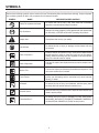
OPERATOR’S MANUAL GASOLINE pressure washer RD80770 Your pressure washer has been engineered and manufactured to our high standard for dependability, ease of operation, and operator safety. When properly cared for, it will give you years of rugged, trouble-free performance. WARNING: To reduce the risk of injury, the user must read and understand the operator’s manual before using this product. Thank you for buying a RIDGID® product. SAVE THIS MANUAL FOR FUTURE REFERENCE TABLE OF CONTENTS nIntroduction....................................................................................................................................................................... 2 n Important Safety Instructions............................................................................................................................................ 3 n Specific Safety Rules......................................................................................................................................................... 4 nSymbols..........................................................................................................................................................................5-6 nFeatures..........................................................................................................................................................................7-8 nAssembly......................................................................................................................................................................9-13 n Operation....................................................................................................................................................................14-18 nMaintenance...............................................................................................................................................................19-21 nTroubleshooting............................................................................................................................................................... 22 nWarranty.....................................................................................................................................................................23-25 n Parts Ordering/Service.......................................................................................................................................Back page INTRODUCTION This tool has many features for making its use more pleasant and enjoyable. Safety, performance, and dependability have been given top priority in the design of this product making it easy to maintain and operate. IMPORTANT SAFETY INSTRUCTIONS checked to determine that it will operate properly and perform its intended function. Check for alignment of moving parts, binding of moving parts, breakage of parts, mounting, and any other conditions that may affect its operation. A guard or other part that is damaged must be properly repaired or replaced by an authorized service center to avoid risk of personal injury. WARNING: Read and understand all instructions. Failure to follow all instructions listed below, may result in electric shock, fire and/or serious personal injury. READ ALL INSTRUCTIONS Never leave tool running unattended. Turn power off. Don’t leave tool until it comes to a complete stop. Know your tool. Read the operator’s manual carefully. Learn the machine’s applications and limitations as well as the specific potential hazards related to this tool. Keep the engine free of grass, leaves, or grease to reduce the chance of a fire hazard. Keep guards in place and in working order. Never operate the tool with any guard or cover removed. Make sure all guards are operating properly before each use. Keep the exhaust pipe free of foreign objects. Follow manufacturer’s recommendations for safe loading, unloading, transport, and storage of machine. Remove adjusting keys and wrenches. Form habit of checking to see that keys and adjusting wrenches are removed from tool before turning it on. Be thoroughly familiar with controls. Know how to stop the product and bleed pressure quickly. To reduce the risk of injury, keep children and visitors away. All visitors should wear safety glasses and be kept a safe distance from work area. Keep tool dry, clean, and free from oil and grease. Always use a clean cloth when cleaning. Never use brake fluids, gasoline, petroleum-based products, or any solvents to clean tool. Keep the area of operation clear of all persons, particularly small children, and pets. Stay alert and exercise control. Watch what you are doing and use common sense. Do not operate tool when you are tired. Do not rush. Do not operate the engine in a confined space where dangerous carbon monoxide fumes can collect. Carbon monoxide, a colorless, odorless, and extremely dangerous gas, can cause unconsciousness or death. Do not operate the product while under the influence of drugs, alcohol, or any medication. Use right tool. Don’t force tool or attachment to do a job it was not designed for. Don’t use it for a purpose not intended. Check the work area before each use. Remove all objects such as rocks, broken glass, nails, wire, or string which can be thrown or become entangled in the machine. Dress properly. Do not wear loose clothing, gloves, neckties, or jewelry. They can get caught and draw you into moving parts. Rubber gloves and nonskid footwear are recommended when working outdoors. Also wear protective hair covering to contain long hair. Do not use tool if switch does not turn it off. Have defective switches replaced by an authorized service center. D o not operate the equipment while barefoot or when wearing sandals or similar lightweight footwear. Wear protective footwear that will protect your feet and improve your footing on slippery surfaces. Before cleaning, repairing, or inspecting, shut off the engine and make certain all moving parts have stopped. Disconnect the spark plug wire, and keep the wire away from the plug to prevent accidental starting. Exercise caution to avoid slipping or falling. Avoid dangerous environment. Don’t use in damp or wet locations or expose to rain. Keep work area well lit. Always wear safety glasses with side shields. Everyday eyeglasses have only impact-resistant lenses; they are not safety glasses. Never use in an explosive atmosphere. Normal sparking of the motor could ignite fumes. Don’t overreach or stand on unstable support. Keep proper footing and balance at all times. Do not operate while smoking or near an open flame. Use only recommended accessories. The use of improper accessories may cause risk of injury. Do not operate around dry brush, twigs, cloth rags, or other flammable materials. Follow the maintenance instructions specified in this manual. WARNING: Risk of injection or injury – Do not direct discharge stream at persons. Check damaged parts. Before further use of the tool, a guard or other part that is damaged should be carefully specific safety rules Never store the machine with fuel in the fuel tank inside a building where ignition sources are present, such as hot water and space heaters, clothes dryers, and the like. Never direct a water stream toward people or pets, or any electrical device. Before starting any cleaning operation, close doors and windows. Clear the area to be cleaned of debris, toys, outdoor furniture, or other objects that could create a hazard. If the fuel tank has to be drained, do this outdoors. To reduce the risk of fire and burn injury, handle fuel with care. It is highly flammable. Never pick up or carry a machine while the engine is running. Do not smoke while handling fuel. Never start the machine if ice has formed in any part of the equipment. Add fuel before starting the engine. Never remove the cap of the fuel tank or add fuel while the engine is running or when the engine is hot. Do not use acids, alkalines, solvents, flammable material, bleaches, or industrial grade solutions in this product. These products can cause physical injuries to the operator and irreversible damage to the machine. Loosen fuel cap slowly to release pressure and to keep fuel from escaping around the cap. Replace all fuel tank and container caps securely. Wipe spilled fuel from the unit. Move 30 feet away from refueling site before starting engine. Always operate the machine on a level surface. If the engine is on an incline, it could seize due to improper lubrication (even at the maximum lubricant level). If fuel is spilled, do not attempt to start the engine but move the machine away from the area of spillage and avoid creating any source of ignition until fuel vapors have dissipated. WARNING: High pressure jets can be dangerous if subject to misuse. The jet must not be directed at persons, animals, electrical devices, or the machine itself. Never attempt to burn off spilled fuel under any circumstances. Never attempt to make any adjustments while the engine (motor) is running (except where specifically recommended by the manufacturer). Before storing, allow the engine to cool. Store fuel in a cool, well-ventilated area, safely away from spark and/or flame-producing equipment. Protective covers must always cover rotating parts when the engine is running. Store fuel in containers specifically designed for this purpose. Keep cooling air intake (recoil starter area) and muffler side of the engine at least 3 feet away from buildings, obstructions, and other burnable objects. Empty fuel tank and restrain the unit from moving before transporting in a vehicle. Keep the engine away from flammables and other hazardous materials. When servicing use only identical replacement parts. Use of any other parts may create a hazard or cause product damage. Keep away from hot parts. The muffler and other engine parts become very hot; use caution. Only use cold water. Do not touch the spark plug and ignition cable when starting and operating the engine. Make sure minimum clearance of 3 feet is maintained from combustible materials. Check fuel hoses and joints for looseness and fuel leakage before each use. Never spray close to the surface to be cleaned as you can damage the surface. Check bolts and nuts for looseness before each use. A loose bolt or nut may cause serious engine problems. Do not use the spring clip for support of human weight, playground equipment, or athletic or overhead lifting of a load. Holds up to 5 lbs. Always refuel outdoors. Never refuel indoors or in a poorly ventilated area. Save these instructions. Refer to them frequently and use them to instruct other users. If you loan someone this tool, loan them these instructions also. SYMBOLS Some of the following symbols may be used on this tool. Please study them and learn their meaning. Proper interpretation of these symbols will allow you to operate the tool better and safer. SYMBOL NAME DESIGNATION/EXPLANATION Read The Operator’s Manual To reduce the risk of injury, user must read and understand operator’s manual before using this product. Eye Protection Always wear safety goggles or safety glasses with side shields and, as necessary, a full face shield when operating this product. Safety Alert Precautions that involve your safety. Hot Surface To reduce the risk of injury or damage, avoid contact with any hot surface. Risk of Injections To reduce the risk of injection or injury, never direct a water stream towards people or pets or place any body part in the stream. Leaking hoses and fittings are also capable of causing injection injury. Do not hold hoses or fittings. Risk of Explosion Fuel and its vapors are explosive and can cause severe burns or death. Risk of Fire Fuel and its vapors are extremely flammable and explosive. Fire can cause severe burns or death. Toxic Fumes Gas products emit carbon monoxide, an odorless, colorless, poison gas. Breathing carbon monoxide can cause nausea, fainting, or death. Kickback To reduce the risk of injury from kickback, hold the spray wand securely with both hands when the machine is on. Electric Shock Failure to use in dry conditions and to observe safe practices can result in electric shock. Chemical Burns To reduce the risk of injury or damage, DO NOT USE ACIDS, ALKALINES, BLEACHES, SOLVENTS, FLAMMABLE MATERIAL, OR INDUSTRIAL GRADE SOLUTIONS in this product. SYMBOLS The following signal words and meanings are intended to explain the levels of risk associated with this product. SYMBOL SIGNAL MEANING DANGER: Indicates an imminently hazardous situation, which, if not avoided, will result in death or serious injury. WARNING: Indicates a potentially hazardous situation, which, if not avoided, could result in death or serious injury. CAUTION: Indicates a potentially hazardous situation, which, if not avoided, may result in minor or moderate injury. CAUTION: (Without Safety Alert Symbol) Indicates a situation that may result in property damage. SERVICE Servicing requires extreme care and knowledge and should be performed only by a qualified service technician. For service we suggest you return the product to the nearest AUTHORIZED SERVICE CENTER for repair. When servicing, use only identical replacement parts. WARNING: To avoid serious personal injury, do not attempt to use this product until you read thoroughly and understand completely the operator’s manual. Save this operator’s manual and review frequently for continuing safe operation and instructing others who may use this product. Call RIDGID® customer service for assistance. WARNING: The operation of any power tool can result in foreign objects being thrown into your eyes, which can result in severe eye damage. Before beginning power tool operation, always wear safety goggles or safety glasses with side shields and a full face shield when needed. We recommend Wide Vision Safety Mask for use over eyeglasses or standard safety glasses with side shields. Always use eye protection which is marked to comply with ANSI Z87.1. FEATURES PRODUCT SPECIFICATIONS Engine Size.....................................................................................................................................................................389cc Fuel Tank Capacity................................................................................................................................................. 3.5 gallons Maximum Pounds Per Square Inch Pressure*.......................................................................................................... 3,800 psi Maximum Gallons Per Minute*.......................................................................................................................................4 gpm Maximum Inlet Water Temperature.................................................................................................................................104˚F *Max. rating determined by PWMA Standard 101 hose storage bag Choke Fuel valve lever throttle lever Recoil starter Nozzles and nozzle holder crane lifting hook WAND Storage holster MOVING handle Spray wand trigger handle fuel tank Trigger with lock out Muffler shield pressure/Flow adjustment handle Honda engine Frame Support Fig. 1 FEATURES KNOW YOUR pressure washer PRESSURE/flow adjustment handle See Figure 1. The safe use of this product requires an understanding of the information on the tool and in this operator’s manual as well as a knowledge of the project you are attempting. Before using this product, familiarize yourself with all operating features and safety rules. Use the pressure/flow adjustment handle to change the pressure/flow levels of the cleaning stream for acceptable pressure/flow for every project. PRESSURE RELIEF VALVE crane lifting hook The pressure relief valve prevents unsafe pressure levels from building up in the pressure washer. It is not uncommon to notice occasional drips from the valve. The crane lifting hook in the center of the unit makes lifting the machine for transportation and/or relocation easy. recoil starter The recoil starter is pulled to start the machine. Fuel tank SPARK ARRESTOR This fuel tank has a maximum 3.5 gallon capacity. This engine is not factory equipped with a spark arrestor. In some areas it is illegal to operate an engine without a spark arrestor. A spark arrestor is available from authorized Honda servicing dealers. Please refer to the engine manual included with this product for more information. FUEL Valve lever The fuel valve lever opens and closes to allow fuel to pass between the fuel tank and the carburetor. The lever must be open to start the engine and should always be closed before storing the machine. THERMAL RELIEF VALVE HONDA GX390 engine To prevent water temperature from reaching harmful levels in the pump, the thermal relief valve will release a small amount of water from a rubber hose. Once the water has reached safe temperature levels, the thermal relief valve will reset itself. This industrial strength Honda engine enables the pressure washer to achieve 3,800 psi (pounds per square inch) at a rate of 4.0 gpm (gallons per minute). Please read the engine manual included with this product. NOTE: This engine comes equipped with an Oil Alert™ system that automatically stops the engine when the lubricant level drops below a safe limit. This system is designed to prevent engine damage caused by not having enough lubricant in the crankcase. trigger handle hose storage bag Pulling the trigger releases a stream of water for high pressure cleaning. The lock out provides protection against unauthorized use or unintentional use. The trigger handle has a grooved gripping surface that provides added control and helps reduce fatigue. trigger with lock out A hose storage bag, located on the back of the machine, provides easy storage and retrieval of hoses. wAND storage holster ON / off switch Store the spray wand and trigger handle in the convenient wand storage holster provided on the side of the machine. The on/off switch must be in the ON position (down) for the engine to run. When the switch is in the OFF position (up), the engine will stop running. ASSEMBLY UNPACKING warning: This product requires assembly. Do not attempt to modify this tool or create accessories not recommended for use with this tool. Any such alteration or modification is misuse and could result in a hazardous condition leading to possible serious personal injury. n Carefully cut the box down the sides then remove the machine and any accessories from the box. Make sure that all items listed in the packing list are included. NOTE: This machine is heavy and requires a minimum of two people to lift. To avoid back injury, lift with your legs and not your back. n Inspect the machine carefully to make sure no breakage or damage occurred during shipping. WARNING: To prevent accidental starting that could cause serious personal injury, always disconnect the engine spark plug wire from the spark plug when assembling parts. n Do not discard packing material until you have carefully inspected and satisfactorily operated the machine. n. Grasp the handle on top of the machine frame. Pull the handle up and back until it locks in place. n If any parts are damaged or missing, please call 1-866-539-1710 for assistance. attaching the wheel assembly See Figure 2. To attach the wheels to the pressure washer base: PACKING LIST Pressure Washer n Locate the axle, flat washers, hitch pins, and wheels. Remove the hitch pin from the axle. 50 ft. High Pressure Hose n Slide the axle through the hole in the center of the wheel then slide a washer over the axle. Spray Wand Trigger Handle n Lift the machine and slide the axle/wheel/washer combination into the wheel mounting hole in the machine base as shown. Wand Storage Holster Quick-Connect Nozzle (5) Nozzle Cleaning Tool n Push the hitch pin into the hole on the end of the axle Injection Hose to secure the wheel assembly. NOTE: The hitch pin should be pushed into the axle until the center of the pin rests on top of the axle. n Repeat with the second wheel. Wheel (2) Flat Washer (2) Axle (2) Hitch Pin (2) Frame Support (2) Hex Bolts & Hex Nuts (4-40 mm, 4-25 mm) 4-Cycle Engine Lubricant (10W30) WASHER Engine Manual Operator’s Manual Warning: If any parts are damaged or missing, do not operate this tool until the missing parts are replaced. Failure to heed this warning could result in serious personal injury. AXLE hitch pin Fig. 2 ASSEMBLY KEY SLOTS installing the frame supports See Figure 3. n Locate the frame supports, hex bolts (2 long and 2 short), and hex nuts. n Raise the end of the pressure washer high enough to access the frame bottom. Position blocks of wood under the machine for support. n Align the hole on the frame support with holes on machine frame. n Insert hex bolts through the hole in the machine frame so that they pass through the frame support. Tighten the bolts to the frame securely using hex nuts. n Repeat on other side. installing the pump oil Cap See Figure 4. Remove and discard the cap securing the plastic bag to the oil pump. Remove the cap from the bag. To install the pump oil cap: Screw the pump oil cap into the hole covering the lubricant reservoir. PUMP OIL CAP CAUTION: Failure to install pump oil cap may result in decreased pump life. installing the wand storage holster See Figure 4. Place key slots (on back of wand storage holster) over the two bolts. Push the holster against the frame. When the bolts are through the key slots, push the holster toward the floor. Tighten the hex nuts. Fig. 4 hex bolts (short) WARNING: Make sure the nozzle and hose connections are secure before starting the machine. A non-secured accessory could become a projectile if not properly installed which could result in serious injury. hex bolts (long) assembling the trigger handle hex NUTs See Figure 5. n Place the threaded end of the spray wand in the connector on the end of the trigger handle. n Turn the connector clockwise until it stops. This secures the spray wand in place. n When not in use, remove the spray wand from the trigger handle by turning the connector counterclockwise. Store the unassembled spray wand in the wand storage holster. frame support Fig. 3 10 ASSEMBLY attaching INJECTION hose trigger handle See Figure 7. Before detergent can be used with this machine, the injection hose must be attached. n Remove the clear injection hose. Uncoil the hose. n Push the open end of the injection hose securely over the fitting. n Place the filtered end of the injection hose in the bottle of detergent. GROOVED GRIPPING SURFACE Injection hose CONNECTOR SPRAY WAND Fig. 5 connecting the high pressure hose to the trigger handle See Figure 6. n Remove the high pressure hose from the storage bag and uncoil the hose. Injection hose fitting n Pull back and hold the quick-connect collar on the high pressure hose. Insert the inlet coupler on the trigger handle into the collar. n Release the collar and push until it locks into place. Pull on the hose to be certain it is properly secured. Fig. 7 high PRESSURE HOSE quick-connect COLLAR inlet coupler Fig. 6 11 ASSEMBLY adding lubricant to the engine warning See Figure 8. NOTE: This machine has been shipped with approximately 2 oz. of lubricant in the engine from testing. You must add lubricant to the engine before starting it the first time. Gasoline and its vapors are highly flammable and explosive. To prevent serious personal injury and property damage, handle gasoline with care. Keep away from ignition sources, handle outdoors only, do not smoke while adding fuel, and wipe up spills immediately. This engine comes with a feature that will shut off the engine when a specific lubricant level is not maintained. The engine will not restart until an appropriate lubricant level is reached. n Place pressure washer on a flat, level surface. adding gasoline to THE FUEL tank n Unscrew the cap / dipstick by turning counterclockwise. See Figure 9. When adding gas to the pressure washer, make sure the unit is sitting on a flat, level surface. If the engine is hot, let the pressure washer cool before adding gas. Always fill the fuel tank outdoors with the machine turned off. n Using 4-stroke engine lubricant (10W30), fill to the upper level of the lubricant filler neck (4-cycle engine lubricant provided). n Replace the cap / dipstick and securely tighten. NOTE: Use unleaded gas only. Do not mix lubricant with gas. n Clean up any spills before starting the engine. NOTE: This engine has a total lubricant capacity of 32 oz. (.95 liters). However, since a small amount of lubricant was put in the machine at the factory, the entire bottle of lubricant may not be needed. n Before removing the fuel cap, clean the area around it. Remove the fuel cap. n Insert a clean funnel into the fuel tank then slowly pour gasoline into the tank. Fill tank to approximately 1/2 in. below the top of the tank neck (this allows for fuel expansion). CAP / DIPSTICK UPPER level n Replace fuel cap and tighten securely. n Clean up any spills before starting the engine. FUEL CAP FUNNEL LOWER Level Fig. 8 Fig. 9 12 ASSEMBLY connecting the garden hose to the pressure washer warning See Figure 10. The water supply must come from a clean water source (e.g. public water main or well) with the following specifications: Make sure the nozzle and hose connections are secure before starting the machine. A non-secured accessory could become a projectile if not properly installed which could result in serious injury. • 8 gpm flow rate (minimum) • 30 psi (minimum) connecting the high pressure hose to the pump NEVER use hot water or standing water from pools, lakes, etc. Use only a reinforced, high-quality garden hose with the following requirements: See Figure 11. n Push the inlet coupler into the collar until it clicks in place. (Use only steel braided, reinforced hose rated to a minimum 4,000 psi.) • 5/8 in. diameter hose (minimum), 3/4 in. diameter hose (recommended) n Pull on the hose to be certain it is properly secured. BEFORE connecting the garden hose to the pressure washer: n Run water through the hose for 30 seconds to clean any debris and air from the hose. n Inspect the filter in the water intake. n If the filter is damaged or dirty, do not use the machine until the filter has been cleaned or replaced. quick-connect collar To connect the garden hose to the machine: n Uncoil the garden hose. NOTE: There must be a minimum of 50 feet of unrestricted hose between the pressure washer intake and the hose faucet or shut off valve (such as a “Y” shut off connector). n With the hose faucet turned completely off, attach the end of the garden hose to the water intake. Hand tighten. water intake Fig. 11 garden hose Fig. 10 13 OPERATION Applications WARNING: You may use this product for the purposes listed below: Do not allow familiarity with tools to make you careless. Remember that a careless fraction of a second is sufficient to inflict severe injury. Remove dirt and mold from decks, cement patios, WARNING: General Instruction Always wear safety goggles or safety glasses with side shields when operating tools. Failure to do so could result in objects being thrown into your eyes resulting in possible serious injury. Do not operate this machine without the water supply connected and turned on. Operating the pressure washer with the water turned off will void your warranty and damage the machine. Never run this pressure washer for more than two (2) minutes without pulling the trigger to allow cool water to enter the pump and the heated (recirculated) water to exit. house siding, etc. Clean cars, boats, motorcycles, outdoor furniture, grills, etc. WARNING: Before attempting to start this product, always do the following: Do not use any attachments or accessories not recommended by the manufacturer of this tool. The use of attachments or accessories not recommended can result in serious personal injury. nConnect all hoses as described in the Assembly section. nCheck all fluid levels. nTurn the garden hose on then squeeze the trigger to relieve air pressure. Hold the trigger until a steady stream of water appears and all “sputtering” from the spray wand has stopped. WARNING: Never direct a water stream toward people or pets, or any electrical device. Failure to heed this warning could result in serious injury. 14 OPERATION ON caution : Do not run the pump without the water supply connected and turned on as this will result in damage to the pump. OFF starting and stopping the pressure washer SWITCH See Figures 12 - 15. NOTE: Before starting the engine, read the engine operator’s manual. To start: nPlace the fuel valve lever in the on position. n If the engine is cold, move the choke lever to the start position. As the engine warms, move the choke to the run position. If the engine is warm, leave the choke lever in the run position. n Move the throttle lever away from the MAX position (pushed to the right) to about one-third of the way towards the MIN position (pushed to the left). n Place the ON / OFF Switch in the ON ( l ) position. nGrasp the recoil starter and pull slowly until resistance is felt. Give the recoil starter a short, brisk pull to start the engine. NOTE: If starting is difficult, release the pressure in the spray wand by pulling the trigger. n Move the throttle lever to the MAX position once the machine is running. Fig. 13 RECOIL STARTER Fig. 14 START RUN Choke Fuel valve lever MAX MIN OFF ON Fig. 15 throttle lever To stop: Recoil starter n Move the throttle lever to the MIN position. Fig. 12 n Place the ON / OFF switch in the OFF ( O ) position. n Turn the fuel valve lever off. 15 OPERATION SLOT WARNING Never direct water stream towards people or pets, or place any part of the body in the stream path as this may cause injection type injuries. Leaking hoses and fittings are also capable of causing injection injuries. WARNING Hold the handle and wand securely with both hands. Expect the trigger handle to move when the trigger is pulled due to reaction forces. Failure to do so could cause loss of control and injury to yourself and others. TRIGGER Lock out Fig. 16 using the trigger See Figure 16. For greater control and safety, keep both hands on the trigger handle at all times. n Pull and hold trigger. n To stop water flow, release the trigger. To engage the lock out: n Push up on the lock out until it clicks into the slot. DO NOT remove the lock out feature from the trigger handle. To disengage the lock out: n Push the lock out down and into its original position. To increase or decrease the water flow (discharge pressure) using the pressure adjustment handle: n Release the trigger. n Turn the pressure adjustment handle on the pump to increase or decrease the water flow (discharge pressure). 16 OPERATION QUICK-CONNECT collar warning Make sure the nozzle and hose connections are secure before starting the machine. A non-secured accessory could become a projectile if not properly installed which could result in serious injury. “CLICK” SELECTing the correct QUICK-CONNECT NOZZLE FOR THE JOB nozzle spray wand See Figure 17. Before starting any cleaning job, determine the best nozzle for the job. Each of the nozzles has a different spray pattern. The nozzle patterns are: 40˚ (for medium pressure), 25˚ (for general purpose or large surfaces), 15˚ (for tough jobs), 0˚ (for spot cleaning or high-to-reach areas), and the Soap Blaster™ nozzle (for long and short range cleaning). NOTE: For a gentle rinse, select the Soap Blaster™ nozzle. Scouring the surface requires a more direct spray of water. Select the 0˚ nozzle for tough jobs. Apply detergent using the Soap Blaster™ nozzle. Fig. 17 warning Never lift or carry this machine using the moving handle. Do not move this machine by pulling on the hoses. MOVING the pressure washer caution: See Figure 18. NEVER change nozzles without locking the lock out on the trigger. n Place ON / OFF Switch in the OFF ( O ) position. n Standing at the back of the machine, grasp the handle firmly with both hands. n Tilt the machine toward you until it balances on the wheels then roll the machine to the desired position. Using the quick-connect collar, changing nozzles is easy. nTurn off the pressure washer and shut off the water supply. Pull trigger to release water pressure. To connect a nozzle to the trigger handle: n Engage the lock out on the trigger handle by pushing up on the lock out until it clicks into the slot. n Push the nozzle into the quick-connect collar until it clicks in place and is secured properly. To disconnect a nozzle from the trigger handle once the cleaning job is complete: nTurn off the pressure washer and shut off the water supply. Pull trigger to release water pressure. n Engage the lock out on the trigger handle by pushing up on the lock out until it clicks into the slot. n Remove the nozzle by placing hand over nozzle then pulling back the quick-connect collar. Place nozzle in the nozzle storage area on the top of the machine. to move the machine Fig. 18 17 OPERATION using the pressure washer See Figure 19. nTurn off the pressure washer and shut off the water supply. Pull trigger to release water pressure. n Engage the lock out on the trigger by pushing up on the lock out until it clicks into the slot. n Select the correct nozzle for the job: • Use lower pressure nozzle (green or white) to wash items such as a car or boat. • Use higher pressure nozzle (red or yellow) for jobs such as stripping paint and degreasing the driveway. When using these nozzles, test a small area first to avoid surface damage. n Start at the top of the area and work down, overlapping strokes. Keep all hoses away from the muffler. For the most effective cleaning, the spray nozzle should be between 8 in. and 24 in. from the surface to be cleaned. If the spray is too close it can damage the cleaning surface. injection hose NOTE: See Washing with Detergent for detergent application. Detergent CONTAINER washing with detergent Use only detergents designed for pressure washers (household detergents, acids, alkalines, bleaches, solvents, flammable material, or industrial grade solutions can damage the pump). Many detergents require mixing prior to use. Prepare cleaning solution as instructed on the solution bottle. ALWAYS test detergents first in an area that is hidden. n Place the injection hose in the bottom of the detergent bottle/container. DO NOT run chemicals through the inlet of the pump; use the chemical injection port only. n Install the black nozzle on the spray wand. n Spray the detergent on a dry surface using long, even, overlapping strokes. To prevent streaking, do not allow detergent to dry on the surface. Keep all hoses away from the muffler. Before shutting off the engine: n Place the injection hose in a bucket of clean water. n Flush for 1 - 2 minutes (spray clear water through the spray wand). n Shut off the engine. NOTE: Shutting OFF ( O ) the engine will not relieve pressure in the system. Pull trigger to release water pressure. See Using the Pressure Washer for rinsing instructions. 18 Fig. 19 maintenance nozzle maintenance WARNING: See Figure 20. Excessive pump pressure (a pulsing sensation felt while squeezing the trigger) may be the result of a clogged or dirty nozzle. When servicing, use only identical replacement parts. Use of any other parts may create a hazard or cause product damage. nTurn off the pressure washer and shut off the water supply. Pull trigger to release water pressure. WARNING: nRemove the nozzle from the spray wand. Always wear safety goggles or safety glasses with side shields during power tool operation or when blowing dust. If operation is dusty, also wear a dust mask. NOTE: Never point the spray wand at your face. nUsing the nozzle cleaning tool provided, free any foreign materials clogging or restricting the nozzle. nUsing a garden hose, flush debris out of nozzle by back flushing (running the water through the nozzle backwards or from the outside to the inside). WARNING: nReconnect the nozzle to the spray wand. Before inspecting, cleaning or servicing the machine, shut off engine, wait for all moving parts to stop, and disconnect spark plug wire and move it away from spark plug. Failure to follow these instructions can result in serious personal injury or property damage. n Turn on the water supply and start the engine. nozzle cleaning tool nozzle NOTE: The Honda GX390 engine has a separate warranty found in the engine manual (included with this product). GENERAL MAINTENANCE Avoid using solvents when cleaning plastic parts. Most plastics are susceptible to damage from various types of commercial solvents and may be damaged by their use. Use clean cloths to remove dirt, dust, lubricant, grease, etc. Fig. 20 WARNING: Do not at any time let brake fluids, gasoline, petroleumbased products, penetrating lubricants, etc., come in contact with plastic parts. Chemicals can damage, weaken or destroy plastic which may result in serious personal injury. Only the parts shown on the parts list are intended to be repaired or replaced by the customer. All other parts should be replaced at an authorized service center. Before running the engine, perform the following preoperation steps: nCheck that all bolts, nuts, etc., are securely tightened. nMake sure the air filter is clean. nCheck both the engine lubricant level and the fuel tank level; refill as needed. nInspect the work area for hazards. nIf there is excessive noise or vibration, stop the unit immediately. 19 maintenance storing the pressure washer pump maintenance See Figures 21 - 22. It is important to store this product in an area that will not experience freezing temperatures. Always empty water from hoses and pump, and empty fuel from the fuel tank. We recommend having the pump lubricant changed every 200 hours to ensure longer life of the machine. This service should be performed by an authorized service center. to store the machine NOTE: Use of a fuel stabilizer and pump saver will give you better performance and increase the life of the machine. After the machine has cooled completely: Discharge Fuel: Drain the fuel tank completely. Stored gas can go stale in 30 days. Engine Lubricant: Drain the lubricant and replace with fresh, clean lubrificant. release pin Spark Plug: nDisconnect spark plug wire and remove the spark plug. Pour about a teaspoon of clean, air-cooled, four-cycle lubricant through the spark plug hole into the combustion chamber. WAND STORAGE HOLSTER nLeaving the spark plug out, pull the starter cord two or three times to coat the inside of the cylinder wall. nInspect the spark plug and clean or replace, as necessary. nReinstall the spark plug, but leave the spark plug wire disconnected. Air Filter: nClean or replace the air filter according to engine manufacturer instructions. (See engine manual.) Fig. 21 Hoses and Pump: Flush the injection hose with clean water for 1-2 minutes. Remove all hoses. Empty the pump by pulling on the recoil starter about 6 times. This should remove most of the liquid from the pump. Spray Wand and Trigger Handle: Unscrew the spray wand from the trigger handle and store in the wand storage holster. Moving Handle: To collapse the moving handle for storage, pull and hold the release pin while pushing the handle down. preparing for use after storage nPull the recoil starter grip three or four times to clean lubricant from the combustion chamber. nRemove spark plug from the cylinder. Wipe lubricant from the spark plug and return it to the cylinder. Fig. 22 nReconnect the spark plug wire. nRefuel the machine as described earlier in the operator’s manual. 20 maintenance periodic maintenance schedule table NOTE: For engine repair, service, and warranty, please see the Honda engine manual, call 1-(770)-497-6400, or visit the Honda website at www.honda-engines.com. Servicing requires extreme care and knowledge and should be performed only by a qualified service technician. For service we suggest you return the product to your nearest authorized service center for repair. When servicing, use only identical replacement parts. periodic maintenance schedule table Maintenance Items Every Every 8 hrs.20 hrs. Every 50 hrs. Replace fuel filter *** Change engine lubricant * or ** X Change pump lubricant * or *** Clean water inlet filter X Every 200 hrs. Every 500 hrs. Every 1,000 hrs. X X * Initial lubricant change should be performed after the first 20 hours of operation. Thereafter, change lubricant every 50 hours of use. Do not pour old lubricant down sewage drains, into garden soil, or into open streams. Your local zoning or environmental regulations will give you more detailed instruction on proper disposal. ** Read the Honda owner’s manual for information. *** Have performed by your nearest service center. 21 TROUBLESHOOTING Problem Engine fails to start Cause 1. Engine switch is in the off position. Solution 1. Move switch to start. 2. Fuel valve lever is OFF.2. Move the lever to ON. 3. No fuel in tank. 3. Fill tank. 4. Spark plug shorted or fouled. 4. Replace spark plug. 5. Spark plug is broken (cracked porcelain or electrodes broken). 5. Replace spark plug. 6. Ignition lead wire shorted, broken, 6. Replace lead wire or attach to spark or disconnected from spark plug. plug. 7. Ignition inoperative. 7. Contact authorized service center. 8. Lubricant level is low. 8. Add lubricant to the engine. Engine hard to start 1. Water in gasoline. 1. Drain entire system and refill with fresh fuel. 2. Engine is under or over choked.2. Adjust choke as necessary. 3. Weak spark at spark plug. 3. Contact authorized service center. 4. Recoil is tight. 4. Release the pressure in the spray wand by pulling the trigger. Engine lacks power 1. Dirty air filter. 1. Clean or replace air filter. 2. Clogged fuel filter.2. Replace fuel filter. Detergent fails to mix with spray 1. Detergent injection hose is not 1. Insert injection hose into detergent properly submerged. storage bucket. 2. High pressure nozzle attached.2. Use low pressure nozzle (black) to apply detergent. 3. Injection hose is clogged/kinked. 3. Remove and replace injection hose. 4. Chemical injector is clogged. 4. Clean or replace injector. Spray wand sputters 1. Air in garden hose. 1. Prime hose. Pull the switch trigger and hold until steady stream of water. 2. Diameter of garden hose is2. Use minimum of 5/8 in. hose. incorrect. 3. Flow rate is insufficient. 3. Call the local utility company. 4. Nozzle is clogged. 4. Clean nozzle as instructed in the Maintenance section. 22 warranty EVAPORATIVE EMISSION CONTROL WARRANTY STATEMENT YOUR WARRANTY RIGHTS AND OBLIGATIONS Your new RIDGID® brand gasoline powered product complies with all applicable U.S. EPA, Environment Canada, and State of California emissions regulations. The evaporative emissions portion of this coverage, as described below, is provided by Techtronics Industries North America, Inc. Separate emissions warranty coverage for other emissions related components is provided by the engine manufacturer, as stated in a separate “Emission Control System Warranty” included with this product. Of course, this product also includes a warranty that is not limited to emissions related components, as described elsewhere in this operator’s manual. CALIFORNIA EVAPORATIVE EMISSION CONTROL WARRANTY STATEMENT The California Air Resources Board and Techtronics Industries North America, Inc. , are pleased to explain the evaporative emission control system’s warranty on your 2007 model year pressure washer. In California, new equipment that uses small off-engines must be designed, built, and equipped to meet the State’s stringent anti-smog standards. Techtronics Industries North America, Inc. must warrant the evaporative emission control system on your pressure washer for the period listed below, provided there has been no abuse, neglect or improper maintenance of your equipment. Your evaporative emission control system may include parts such as: carburetors, fuel tanks, fuel lines, fuel caps, valves, canisters, filters, vapor hoses, clamps, connectors, and other associated components. For engines less than or equal to 80 cc, only the fuel tank is subject to the evaporative emission control warranty requirements of this section. MANUFACTURER’S WARRANTY COVERAGE: This evaporative emission control system is warranted for two years. If any evaporative emission-related part on your equipment is defective, the part will be repaired or replaced by Techtronics Industries North America, Inc. OWNER’S WARRANTY RESPONSIBILITIES: As the pressure washer owner, you are responsible for performance of the required maintenance listed in your owner’s manual. Techtronics Industries North America, Inc. recommends that you retain all receipts covering maintenance on your pressure washer, but Techtronics Industries North America, Inc. cannot deny warranty solely for the lack of receipts. As the pressure washer owner, you should, however, be aware that Techtronics Industries North America, Inc. may deny you warranty coverage if your pressure washer or a part has failed due to abuse, neglect, or improper maintenance or unapproved modifications. You are responsible for presenting your pressure washer to a Techtronics Industries North America, Inc. distribution center or service center as soon as the problem exists. The warranty repairs should be completed in a reasonable amount of time, not to exceed 30 days. If you have a question regarding your warranty coverage, you should contact Techtronics Industries, Inc., attn: Pressure Washer Technical Service at (toll free) 1-866-539-1710. 23 warranty DEFECTS WARRANTY REQUIREMENTS: (4) Repair or replacement of any warranted part under the warranty provisions of this article must be performed at no charge to the owner at a warranty station. (5) Notwithstanding the provisions of subsection (4) above, warranty services or repairs must be provided at distribution centers that are franchised to service the subject engines or equipment. (6) The owner must not be charged for diagnostic labor that leads to the determination that a warranted part is in fact defective, provided that such diagnostic work is performed at a warranty station. (7) Throughout the evaporative emission control system’s warranty period set out in subsection (b)(2), the manufacturer issuing the warranty must maintain a supply of warranted parts sufficient to meet the expected demand for such parts. (8) Manufacturer approved replacement parts must be used in the performance of any warranty maintenance or repairs and must be provided without charge to the owner. Such use will not reduce the warranty obligations of the manufacturer issuing the warranty. (9) The use of any add-on or modified parts will be grounds for disallowing a warranty claim made in accordance with this article. The manufacturer issuing the warranty will not be liable under this Article to warrant failures of warranted parts caused by the use of an add-on or modified part. (10) The manufacturer issuing the warranty shall provide any documents that describe the war ranty procedures or policies within five working days of request by the Air Resources Board. (a) The warranty period begins on the date the engine or equipment is delivered to an ultimate purchaser. (b) General Evaporative Emissions Warranty Coverage. The equipment must be warranted to the ultimate purchaser and any subsequent owner that the evaporative emission control system when installed was: (1) Designed, built, and equipped so as to conform with all applicable regulations; and (2) Free from defects in materials and workmanship that cause the failure of a warranted part for a period of two years. (c) The warranty on evaporative emissions-related parts will be interpreted as follows: (1) Any warranted part that is not scheduled for replacement as required maintenance in the written instructions must be warranted for the warranty period defined in subsection (b)(2). If any such part fails during the period of warranty coverage, it must be repaired or replaced by the manufacturer issuing the warranty. Any such part repaired or replaced under the warranty must be warranted for a time not less than the remaining warranty period. (2) Any warranted part that is scheduled only for regular inspection in the written instructions must be warranted for the warranty period defined in subsection (b)(2). A statement in such written instructions to the effect of “repair or replace as necessary” will not reduce the period of warranty coverage. Any such part repaired or replaced under warranty must be warranted for a time not less than the remaining warranty period. (3) Any warranted part that is scheduled for replacement as required maintenance in the written instructions must be warranted for the period of time prior to the first scheduled replacement point for that part. If the part fails prior to the first scheduled replacement, the part must be repaired or replaced by the manufacturer issuing the warranty. Any such part repaired or replaced under warranty must be warranted for a time not less than the remainder of the period prior to the first scheduled replacement point for the part. EMISSION WARRANTY PARTS LIST: 1) Fuel Line 2) Fuel Line Clamps 3) Fuel Line Fittings Written instructions for the maintenance and use of the 24 WARRANTY RIDGID® PRESSURE WASHER 3 YEAR LIMITED WARRANTY RIDGID, INC. AND TECHTRONIC INDUSTRIES NORTH AMERICA, INC. MAKE NO WARRANTIES, REPRESENTATIONS OR PROMISES AS TO THE QUALITY OR PERFORMANCE OF ITS PRESSURE WASHERS OTHER THAN THOSE SPECIFICALLY STATED IN THIS WARRANTY. Proof of purchase must be presented when requesting warranty service. This product is manufactured by Techtronic Industries North America, Inc. The trademark is licensed from RIDGID, Inc. All warranty communications should be directed to Techtronic Industries North America, Inc., attn: Pressure Washer Technical Service at (toll free) 1-866-539-1710. HOW TO OBTAIN SERVICE To obtain service for this RIDGID® presure washer you must return it, freight prepaid, or take it in to a manufacturerauthorized service center for RIDGID® pressure washers. You may obtain the location of the authorized service center nearest you by calling (toll free) 1-866-539-1710 or by logging on to the RIDGID® website at www.ridgid.com. When requesting warranty service, you must present the original dated sales receipt. The authorized service center will repair any faulty workmanship, and either repair or replace any part covered under the warranty, at our option, at no charge to you. WHAT IS COVERED UNDER THE 3 YEAR LIMITED WARRANTY This RIDGID® pressure washer is warranted to the original purchaser only to be free from defects in material and workmanship subject to certain exceptions and limitations stated below, for a period of three (3) years after date of purchase. Commercial and rental use: For commercial and/or rental use of models up to 3200 PSI, the warranty is limited to 120 days after date of purchase. ADDITIONAL LIMITATIONS Warranties for other RIDGID® products may vary. To the extent permitted by applicable law, all implied warranties, including warranties of MERCHANTABILITY or FITNESS FOR A PARTICULAR PURPOSE, are disclaimed. Any implied warranties, including warranties of merchantability or fitness for a particular purpose, that cannot be disclaimed under state law are limited to three years from the date of purchase. Techtronic Industries North America, Inc., and RIDGID®, Inc., are not responsible for direct, indirect, incidental, or consequential damages. Some states do not allow limitations on how long an implied warranty lasts and/or do not allow the exclusion or limitation of incidental or consequential damages, so the above limitations may not apply to you. This warranty gives you specific legal rights, and you may also have other rights which vary from state to state. WHAT IS NOT COVERED This warranty does not apply to damage from misuse, alterations, abuse, normal wear and tear, lack of maintenance, accidents, or repairs made or attempted by anyone other than an authorized service center for RIDGID® pressure washers. Normal Wear: This warranty does not cover repair when normal use has exhausted the useful life of a part such as a high pressure hose, spray wand, nozzles, trigger handle, supply hoses, quick couplers, gaskets, valves, pistons, pump valve assemblies, o-rings, water and oil seals. Additionally, the warranty on this pressure washer does not cover damage due to freezing, chemical deterioration, rust, corrosion, scale build up, thermal expansion, or failure to maintain adequate water supply as instructed in the Operator’s Manual. This warranty applies to product sold in the U.S.A., Canada, and Mexico only. Please consult RIDGID’s website at www.ridgid.com or call (toll free) 1-866-539-1710 to locate your nearest manufacturer-authorized RIDGID® service facility for warranty and non-warranty service on this RIDGID® pressure washer. This warranty does not cover freight or labor charges associated with the inspection and testing of pressure washers which are found not to be a valid warranty claim. Gasoline Engine - Warranty: The gasoline engine on this pressure washer is separately warranted by the engine manufacturer and is serviced through the engine manufacturer’s authorized service center network. Ridgid, Inc., and Techtronic Industries North America, Inc., disclaim any and all express or implied warranties with respect to the gasoline engine. Techtronics Industries North America, Inc. P.O. Box 35, Hwy. 8 Pickens, SC 29671 25 OPERATOR’S MANUAL GASOLINE pressure washer RD80770 Customer Service Information For parts or service, contact your nearest RIDGID® authorized service center. Be sure to provide all relevant information when you call or visit. For the location of the authorized service center nearest you, please call 1-866-539-1710 or visit us online at www.ridgid.com. The model number of this tool is found on a plate attached to the motor housing. Please record the serial number in the space provided below. When ordering repair parts, always give the following information: Model No. Serial No. 987000-258 12-28-07 (REV:01) 26 RD80770