1
US 20110181242A1
(19) United States
(12) Patent Application Publication (10) Pub. No.: US 2011/0181242 A1
(43) Pub. Date:
Lee
(54)
MULTI-CHEMISTRY BATTERY CHARGING
(52)
Jul. 28, 2011
US. Cl. ...................................................... .. 320/110
SYSTEM AND METHOD OF IDENTIFYING
AND IMPROVED CHARGING TECHNIQUE
FOR PRIMARY AND SECONDARY
DRY-CELL BATTERIES
(76) Inventor:
(57)
ABSTRACT
A microprocessor controlled multi chemistry battery charg
ing system and method for recharging primary and secondary
Wilson Lee, Victoria (AU)
batteries are disclosed. The charger has multiple battery
(21) Appl. No.:
13/121,496
(22) PCT Filed:
Sep. 29, 2009
holder bays With different recess levels to accept up to four
batteries of different siZes and different chemistry types par
ticularly Primary Alkaline, Primary Titanium, Rechargeable
(86)
(30)
PCT No.:
PCT/AU2009/001286
§ 371 (0X1)’
(2), (4) Date:
Mar. 29, 2011
Alkaline Manganese (RAM), NiCd and NiMH batteries. The
microprocessor controlled electronic circuit automatically
identi?es the type of battery to be charged by monitoring and
comparing voltage responses over preset time by supplying
Foreign Application Priority Data
constant charging current. Depending upon the type of bat
tery, the charger controls suitable charging current or current
Sep. 29, 2008
(AU) .............................. .. 2008905047
Publication Classi?cation
(51)
Int. Cl.
H02] 7/04
pulses at different frequencies till battery voltage reaches
preset maximum reference voltage or battery voltage remains
relatively constant beloW preset maximum reference voltage
over preset time period. The charger has built in safety pro
tections, battery tester function, audio visual arrangements to
display status, a variable DC output port and USB ports.
(2006.01)
100
Sysiem
initialization &
Battery insertion
Monitoring
103
(A
Apply Load to test
Voltage7/
101
Battery Condition
& Flashing
indicator
l
___—/
Apply High
I
/i1D5
Current Test
Charge to Battery m
\
N
for up to x minutes
,1107
< Battery Voltage \
Rise
Alkaline Batt Low
,
Current Charging
Routine
‘
achargeable 2D
N DV/MaxWMaxT“
Apply Load to test
Y
MaxVIMaxT'P
Rechargeable Bat!
High Current
Charging Routine
//\<,]1r3
/.|. (P 5,;
Battery Condition W/
\112
Stop Charge,
Reject Battery &
Turn OFF
Indicator
Tum ON indicator
& Maintain Battery
via Trickle Charge
Battery Removed?
m6
NM“
>
}
Patent Application Publication
Jul. 28, 2011 Sheet 1 of6
US 2011/0181242 A1
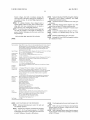
FIGURE 1
100\
System
lnitlalizalion &
Battery inserted?
Battery insertion
Monitoring
103
Apply Load to test
Battery Full
Battery Condition
Voltage?
& Flashing
indicator
104
Apply High
Bad Battery
Current Test
Voltage?
Charge to Battery
for up to x minutes
Y
Battery Voltage
Rise > 1.5V?
Y
110}
Alkaline Bali Low
Rechargeable Bait
Current Charging
Y
Negcj‘hr?ifjmig‘i
Rouline
High Current
'
Charging Routine
N
N
111
Alkaline ZDV/NDV/
Y
‘—__I \—>
M113
Apply Load to test
MaxV/MaxT? >‘Y_°l Battery Condition
Stop Charge,
Reject Battery &
Turn OFF
Test pass?
\112
/l114
‘
k
Indicator
_—__/
/l115
Turn ON Indicator
\_-—_——-—-—e & Maintain Battery e————-————-—-——-Y
via Trickle Charge
Battery Removed? <5
I
Patent Application Publication
Jul. 28, 2011 Sheet 2 0f 6
US 2011/0181242 A1
FIGURE 2
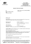
LCD Shows Selected Channel
Number, Battery Charging
Centre Positive & Negative
‘
status & Selected Dc out
Contacts Within Each Slot Are for
Charging 1.2 81 1.5V Batteries.
Voltage Level.
Channel 1, 2, 3 or
4 Select Button
DC Out
Voltage Select
The 2 Round Terminals
Within Each Slot Are for
USB LED
Charging 9V Batteries.
”
Built-in Fan Activates
3"’ & 4*“ Channel LEDs
'
'
When Required to
Power LED
Keep Svstem Cool.
st
“d
1 8: 2 Channel LEDs
DC-OUT LED
2 x High power USB
W
Ports for Charging of
5V Dieital Devices.
)
(
12V Dc Power
‘
/
Input Socket
‘1
m‘
Mg
“WT
E MV-EV-BAV
menu:
6-%-@
Custom mini USB port for future
Variable DC Voltage Output
upgrade — expansion link to an
Socket —- 4.2V, 6V & 8.4V levels
external module that supports
acting as charging power sources
the charging of Lithium-ion
battery packs.
for many personal digital audio &
visual devices.
Patent Application Publication
Jul. 28, 2011 Sheet 3 of6
US 2011/0181242 A1
FIGURE 4
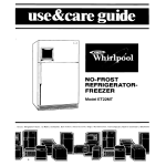
- Variable DC-Out port is ON.
— Graphical illustration of battery cell being
u CAUTION - Care is required when making
charged.
C-Out voltage selection as over-voltage
may lead to damage of equipment being
powered. ALWAYS select voltage ?rst and
then plug in device.
- Battery is being analysed.
\ — Standard charging for
sensitive
batteries.
Select 4.2V —- to power devices accepting
3.0V — 4.5V input.
- Fast charging when applicable.
Select 6V — to power devices accepting 5.0V
— 6.5V input.
f — Battery is charged and ready for use.
Select 8.4V — to power devices accepting
7.0V- 9.0V input.
(I)
w - Sensitive battery has been rezapped
— Sound alert is only active when channel
and ready for use.
a
select is pressed. Alert sequences are as
follows:1 short beep - Channel select
- Battery is bad and or no longer
returned to number 1 position. After 5,
rezappable. Prompt disposal is required
seconds delay with no further key pressed,
charge status of the selected battery is
to avoid eventual battery leakage.
alerted.
- Fan is ON to cool down the internal
circuitry when required. When
FLASHING, fan is not working and for
safety reason, charger only operates in
standard charge mode. When all
batteries are removed from the charger,
fan will be switched off automatically.
No sound — selected channel has no battery.
9
2 short beeps - selected battery is being
charged.
1 long beep — selected battery is charged
and ready for use.
2 long beeps — selected battery is bad.
Patent Application Publication
Jul. 28, 2011 Sheet 4 0f 6
US 2011/0181242 A1
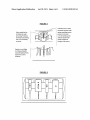
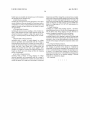
FIGURES
Individual slot has metal
connectors as shown with
Centre metal bar has
insolated side walls
centre metal plate acts as
positive terminal for
preventing 9V battery
terminals from shorting
with 1.2/ 1.5V battery
while the round knobs
terminals.
charging of 9V battery.
Negative metal sliding
bar helps pushing the
connected battery firmly
against the positive
terminals.
1.2/1.5V cylindrical cells
provide suppon: for
Patent Application Publication
Jul. 28, 2011 Sheet 5 0f 6
US 2011/0181242 A1
FIG U R E 7
DC Power In
A
Voltage
USE OUT “
Regulator
Buck
I
.
Converter
_____J
Filter
K
J
v
DC-OUT
‘ ‘I,’
/
\.i‘
\FL/
{/7
Battery 1
I,
[1/
LCD
’
//
’:
X
\
/
‘
Battery 2
\
X/Y‘
LCD D '
rlver
//1~_
'
'
‘
MCU
J\\
.
Battery/3
CONTROLLER \FMi‘ /
—\__
Y
—
"\ //
LEDs
r——*~
VMW/
/
Push
Buttons
____.
Voltage Reference
FAN
Current Sense
Patent Application Publication
Jul. 28, 2011 Sheet 6 0f 6
US 2011/0181242 A1
FIGURE 3
2
.mnOoQWNuomEwM
Jul. 28, 2011
US 2011/0181242 A1
range of short comings that made them unreliable and/or
MULTI-CHEMISTRY BATTERY CHARGING
SYSTEM AND METHOD OF IDENTIFYING
unsafe to use. Clearly there is a need to come up With a
AND IMPROVED CHARGING TECHNIQUE
multi-chemistry battery recharging system that can overcome
FOR PRIMARY AND SECONDARY
DRY-CELL BATTERIES
most if not all of the short-comings knoWn that are reliable
FIELD OF THE INVENTION
for discriminating betWeen primary and secondary batteries.
and safe for consumer use.
[0009]
Several prior art disclosures suggest different means
One method disclosed the measurement and use of internal
[0001] This invention relates to charging of batteries. It
relates to primary batteries Which are generally considered
battery resistances to distinguish betWeen primary alkaline
non-rechargeable and secondary rechargeable batteries. lt
and secondary NiCd batteries as outlined in US. Pat. No.
particularly relates to the multitude of different batteries for a
multitude of different electric and electronic devices.
BACKGROUND
[0002]
As society is becoming increasingly mobile, We see
the rapid adoption of mobile phones, laptop computers, palm
devices, personal stereos, remote controllers and as any par
ent knoWs, a huge array of electronic toys. Batteries are the
poWer source of necessity for these devices Which have
become an everyday part of life Whether at Work, at home and
at play.
[0003] The prior art illustrates a strong lack of options
delivering ef?ciency and effectiveness and fails to provide a
convenient and cost effective solution. Currently, the con
sumer is expected to merely purchase a neW battery every
time a battery goes out.
[0004]
Many people take up rechargeable batteries so that
the batteries can be recharged and reused over and over again.
The disadvantages of rechargeable batteries are that they cost
much more than primary batteries and replacing the Whole
house With a rechargeable system Would be out of the ques
tion for most people. Further, rechargeable batteries lose their
effectiveness and, in particular, their period of time ‘in use’
decreases and they are therefore required to be charged more
frequently over time.
[0005] In addition, rechargeable batteries are rendered
unsuitable for many electronic applications as rechargeable
batteries have a very fast self discharge rate compared to
primary alkaline batteries.
[0006] Further, a recharging battery requires a complicated
battery charger Which adds further cost to the consumer and
can be quite dif?cult or complicated to operate. In addition,
5,600,224. HoWever this method is not reliable as consumer
batteries are becoming complicated in recent time With more
battery types added to the list such as the addition of the neW
breed of advanced formula alkaline batteries With very loW
internal resistances and the environmentally, more friendlier,
NiMH and rechargeable alkaline batteries Which make the
distinguishing line not so apparent. Furthermore as batteries
age, their internal resistances become higher and the values
overlap one another Which make this distinguishing task
using internal resistances even more unreliable.
[0010]
The most commonly seen method employed in
chargers, charge only batteries having a certain predeter
mined feature. These hoWever are not entirely satisfactory
from the combined standpoints of safety, ease of use and more
importantly these do not meet the criteria to be considered as
universal recharging system that accepts most chemistry
types of batteries.
[0011] Also, commonly seen approaches use mechanical or
electronic sWitch selections as a means to distinguish the tWo
battery types and thereafter apply a loW charge current to
primary alkaline batteries and moderate charge current to
rechargeable batteries. These systems rely on the users to
make complicated and often confusing selections that could
lead to Wrong operating settings either through plain human
errors or technical ignorance. The consequences of such
errors Would cause adverse battery leakage, damage to bat
teries and chargers and, in Worst cases, lead to dangerous
battery explosions. Another short coming using this approach
is that the system cannot charge different mix of batteries
simultaneously. This type of chargers usually only can charge
single battery type at a time.
When the battery goes ?at recharging requires an external
[0012]
poWer source, such as a poWer outlet. When the battery is not
charge current safely recharging both types of batteries so
they can co-exist Within a single charging system. This is the
charged effectively, it is cumbersome and impractical to
locate a poWer source When mobile or in transit.
[0007]
There is a complex number and variety of battery
types available on the market that includes rechargeable
nickel cadmium and nickel metal hydride batteries as Well as
primary carbon Zinc, alkaline and rechargeable alkaline bat
teries. Adding further to the complexity and confusion of
rechargeable and non-rechargeable batteries are neW alkaline
Further, in practice there is the use of a common loW
closest system that can overcome many problems encoun
tered previously and is safe to use. HoWever there are short
comings With this technique as Well as it taking at least 15
hours or more to charge up primary alkaline and rechargeable
batteries. Even With the lengthy charge time, this system still
cannot fully charge up many high capacity rechargeable
NiMH batteries.
variants called Titanium and long lasting advanced formula
[0013]
batteries and so forth that truly making recharging batteries a
mine ?eld for many people.
and effective method to automatically detect and distinguish
[0008] For one reason or the other, primary alkaline batter
ies still remain a part of our ZO everyday life. They are readily
available everyWhere and their toxic Wastes continue to
threaten land?lls and Waterways. Many attempts have been
made to come up With systems that can recharge primary
alkaline as Well as rechargeable batteries to help save money
So there is a need to come up With a more ef?cient
primary and secondary dry-cell batteries Without any involve
ment of the error-prone user interaction described above.
There is also a further need for a faster and improved charging
method that can properly recharge most different battery
types Within a single system.
[0014] The present invention attempts to overcome or at
least ameliorate one or more of the problems of the prior art
and the environment. Up until noW, all recharger systems
and to achieve or at least progress toWards achieving one or
available are at their infancy stage and suffer from a Wide
more of the folloWing objects of the invention.
Jul. 28, 2011
US 2011/0181242 A1
[0015]
It is therefore an object of the present invention to
provide a charger that is capable of identifying primary non
nals to all the charging terminals to sense for the presence of
[0016] It is another object of the present invention to pro
vide a charger that is capable of safely recharging the Widest
batteries across all available battery bays.
[0025] Upon a battery being detected that it is to be con
nected to the charger, the system ?rstly measures the initial
voltage of the battery and compares it With a io preset range of
range of different consumer battery types that belong to both
values and decides if the battery is a neW or fully charged
groups of primary and secondary dry-cell batteries simulta
primary alkaline battery. If it is, then the system Would
promptly indicate the battery is fully charged and stop any
further processing of the said battery. 1f the required condition
rechargeable and secondary rechargeable dry-cell batteries.
neously.
[0017]
It is yet another object of the present invention to
provide a charger that can accommodate several different
is not met, then the system Would apply a relatively constant
siZes, namely AAA, AA, C, D, Prismatic or gum-stick, 9V
test current of the order betWeen 300 to 500 mA to the battery
and N-siZed batteries. The same charger can also further be
expanded to include extra facilities to poWer a range of oth
for a preset period and monitors the rate of voltage change of
the said battery. This is the crucial criteria for identifying
erWise unpoWered devices or charge up different battery
packs in many self-poWered devices.
[0018] It is still yet another object of the present invention
primary and secondary batteries.
[0026] Under this high current testing condition, the volt
to provide a charger that is very easy to use and requires little
or no battery knowledge from the user.
[0019]
age responses of most primary cells including a large percent
age of rechargeable alkaline batteries (though called
“rechargeable” alkaline, these have similar voltage rating of
It is also another object of the present invention to
1 .5V as that of primary alkaline and their charging behaviour
provide a charger that can deliver different rates of fast and
considered the same Which cuts off at 1.7V full charged
sloW charging to the batteries With multiple charge termina
voltage level) and some old NiCd batteries (though NiCd is
classi?ed as secondary battery type, it behaves similar to that
of primary alkaline battery Where its full charged voltage can
tion schemes and multiple safety protection capabilities.
[0020]
It is also yet another object of the present invention
to provide a charger that shoWs detailed information of the
battery conditions and charging status that are easily under
stood.
go up to 1.7V and can accept sloW to moderate charge current
similar to alkaline batteries) Would quickly rise and meet a
certain preset voltage level Which distinguishing themselves
as primary alkaline batteries.
SUMMARY OF THE INVENTION
[0021] According to the invention there is provided multi
chemistry battery charging system and method of identifying
and improved charging technique for primary and secondary
dry-cell batteries. The system provides a battery charger con
structed to accept a variety of different siZes and different
chemistry types of single dry-cell batteries. It is microproces
sor controlled and has electronic circuitry that can identify the
[0027] These batteries Would then be charged using an
appropriate loW to moderate charge current suitable for
recharging of primary alkaline batteries until their preset full
charged voltage is reached at a preferred 1.7V level. The
appropriate channels Would then be sWitched off from further
processing and suitable audio and or visual signals generated
to inform the user of the battery ‘fully charged’ status. Those
voltage responses that overshoot the preset abnormal voltage
different primary and secondary batteries inserted into the
range Would render the batteries as faulty and/or no longer
charger and applies the appropriate prefer charge current and
voltage to safely and properly charge up the batteries.
[0022] The said battery charger is built to have multiple
rechargeable. The appropriate channels Would then be
sWitched off from further processing and suitable audio and
battery holder bays that have different recess levels and slid
ing spring mechanisms that can secure different siZed cylin
bad’ status.
drical dry-cell and prismatic siZed batteries betWeen the posi
tive and negative charging terminals of the charger. Each
and NiCD batteries together With a certain percentage of
alkaline and rechargeable alkaline batteries Would have their
voltage responses rise relatively sloWer than that to the con
battery holder bay also has a contact means that can couple
With the tWo terminals of a 9V battery and together With the
or visual signals generated to inform the user of the ‘battery
[0028]
On the other hand, secondary rechargeable NiMH
dition described earlier. These batteries, regardless of their
sliding spring contact Which pushes at the base of the said 9V
battery and secure it in place to receive the charging poWer.
[0023] The electronic circuitry Within the charger is sub
stantially controlled by means of a single or multiple micro
battery types, have in common very loW internal resistances
and are capable of accepting fast and safe pulse or constant
processors capable of controlling and varying the supplies of
batteries’ voltage responses Would rise sloWly to a preset full
charged voltage range of 1 .40 to 1 .46V over time Which varies
depending on the capacity of the batteries under charge. The
the charging current and voltage sources applied to batteries
appropriately. The sWitching circuits create charge current
pulses at different frequencies to achieve the desired effects of
sloW, medium or fast charge rates suitable for recharging of
multi-chemistry battery types Within the same system. The
said circuitry has multiple sub-circuits knoWn as “channels”
layout in a serial or parallel arrangement that function in
unison yet independently.
[0024]
The charger can be designed to accept DC and orAC
poWer and at poWer on, the system Would perform a series of
self tests and initialiZation routines to ensure the Whole sys
tem is functioning correctly and send out appropriate audio
charging current ranges betWeen 300 m to 500 mA.
[0029] Under this fast charging rate, rechargeable NiMH
battery voltage Would then stay relatively constant at the
above voltage range over a preset period of time. When this
condition is met it signals a full charged status for NIMH
batteries and no further processing to the batteries are
required. With the same fast charge condition, loW-intemal
resistance primary alkaline and rechargeable alkaline batter
ies as Well as NiCd’s voltage responses Would rise much
faster than those of NiMH described earlier and overshoot the
NiMH full charged voltage range of 1.40 to 1.45V and con
tinue to rise further.
and or visual signals to inform the user of its status. The
[0030]
circuitry concerned then constantly sends out electrical sig
the appropriate channels to a sloW to moderate charge current
Once this limit is passed, the system Would sWitch
Jul. 28, 2011
US 2011/0181242 A1
suitable for charging alkaline batteries and the charging pro
batteries at home and at Work. It’s safe, it’s easy to use, it saves
cess continues until the full charge 1.7V limit is reached.
money and helps the environment.
[0031]
During the Whole charging process of all battery
types, the controlling microprocessor(s) Would sense and
measure all battery voltage changes in one second increment
steps and monitor for any abnormal charge responses and or
charge termination criteria to occur so that the charging pro
cess can be terminated promptly and all battery types are
appropriately charged. A combination of multiple charge ter
mination and protection schemes are employed to ensure the
highest safety level can be achieved that includes:
BRIEF DESCRIPTION OF THE DRAWINGS
[0043] In order that the invention is more readily under
stood an embodiment Will be described by Way of illustration
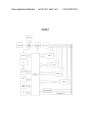
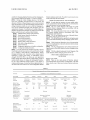
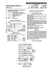
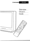
only With reference to the draWings Wherein:
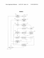
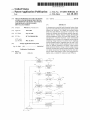
[0044] FIG. 1 is a How diagram of the usage of a multi
chemistry battery charging system in accordance With an
embodiment of the invention;
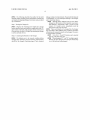
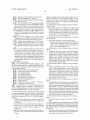
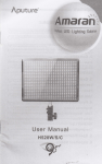
[0045]
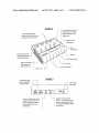
FIG. 2 is an illustrative front vieW of a multi chem
istry battery charging system in accordance With a ?rst
embodiment of the invention;
[0032] Alkaline battery charge-safe protection,
[0033] Faulty battery detection & rejection,
[0046]
FIG. 3 is an illustrative rear vieW of the multi chem
[0034] Overcharge protection,
istry battery charging system of FIG. 2;
[0035]
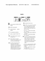
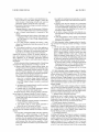
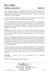
[0047] FIG. 4 is an illustrative operative front display panel
on top of the multi chemistry battery charging system of FIG.
Short circuit protection,
[0036] Wrong polarity Protection,
[0037] Negative delta voltage protection,
[0038]
[0039]
[0040]
[0041]
[0042]
2;
[0048]
Zero delta voltage protection,
Timer Protection,
Temperature protection via built-in cooling fan,
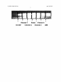
Cooling fan failsafe protection.
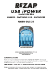
FIGS. 5 and 6 are illustrative vieWs of the mounting
of various siZed batteries in the multi chemistry battery charg
ing system of FIG. 2;
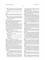
[0049]
FIG. 7 is a diagrammatic vieW of interconnection of
operative parts of the multi chemistry battery charging system
It can be seen that the invention provides a device
Which represents the latest and mo st advanced battery charger
of FIG. 2;
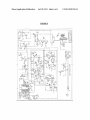
[0050] FIG. 8 is a detailed schematic Circuit Diagram of the
yet. It employs state-of-the-art; multi-chemistry battery
multi chemistry battery charging system of FIG. 2.
charging technology and. Innovative active charge monitor
A PREFERRED EMBODIMENT OF THE
INVENTION
technique to ensure each battery is individually custom
charged. REZAP® PRO is an all-in-one, next generation
battery charger that satis?es all the complex battery needs of
modern family homes. It charges all rechargeable batteries.
Battery Types Guide
Its neW open architecture design ensures it can support a
(non-rechargeable) and secondary (rechargeable). The table
Widest possible range of current and future digital devices. It
beloW shoWs some of their most common features and prop
also alloWs the user to RECYCLE non-rechargeable alkaline
erties:
[0051]
There are tWo main groups of batteries, primary
TABLE 1
Domestic Battery types With some of their common properties.
TYPICAL
FEATURES
Battery
Labelling
Battery Class
NominalVoltage
Available Sizes
Cost Factor
Suffer from Memory
COMMONLY USED DOMESTIC BATTERIES
Carbon
Alkaline
Titanium
RAM
NiCd
NiMH
Lithium
Carbon Zinc,
Heavy Duty,
General purpose
Alkaline
Titanium
Rechargeabke
Alkaline
Manganese
Nickel Cadmium
NiCd
Nickel Metal Hydride
NiMH
Lithium
Li
Primary
Primary
Primary
Secondary
Secondary
Secondary
Primary
1.5V
1.5V
1.5V
1.5V
1.2V
1.2V
1.5V,3V,6V
35
$35
AAA, AA, C, D, 9V, Prismatic (gum-stick)
35%
$3535
353535
35353535
$$$$$
No
No
No
No
No
No
Yes
Effect problem?
Suitable for use
With devices of
Occassional
Moderate
Frequent
Suitable for use
LoW Drain
Moderate to High Drain
High Drain
With devices of
“Drain Rate”
Examples:
Remote controls
Examples:
General light-duty electronic devices, Motorised toys
Examples:
Digital Cameras, Discman, Walkman,
& Torches . . .
Radios and MP3 players . . . (This group of batteries are not
Heavy-duty motorised devices (Also
suitable for use With applications as listed under the “High
support most applications as listed
“Usage-frequency”
Supported By
REZAP ® RBC889
Standard
Drain” column.
Yes
Yes
under Alkaline batteries).
Yes
No
No
Yes
Yes
1
l
1
Up to 25
Up to 600
Up to 500
1
Not Supported
Up to 15
Up to 15
Up to 30
Up to 1000
Up to 1000
Not Supported
Cycle Life
Cycle Life under
REZAP ® RBC889
Jul. 28, 2011
US 2011/0181242 A1
The following describes the method of the multi
leakage or deposit on the terminals. These should be disposed
chemistry battery charging system and method of identifying
and improved charging technique for primary and secondary
[0052]
of immediately to avoid subsequent damage to the charger
dry cell batteries.
and/or electronic devices.
[0055]
Although battery leakage found on some faulty,
damaged or old batteries Will not typically cause imme
Step 1: Turning the Charger On
diate damage to unprotected is skin, it is best to avoid
[0053]
contact, or if contact occurs, immediately Wash the
exposed area With soap and Water.
Plug the 12V sWitching poWer supply into a proper
indoor electrical outlet and connect its output cable to the 12V
input socket at the back of the charger. SWitch on the poWer
from the mains, the blue LED lights up indicating the charger
is active and ready for use.
Step 2: Connecting the Batteries to the Charger
[0054]
The batteries are to be in good condition before
charging them. Batteries With the folloWing characteristics
should not be charged: illustrating signs of rust, chemical
[0056]
Place used batteries to be charged into the charger
slots according to their different siZes as folloWs and ensure
all batteries are connected correctly to the charger. The user is
to note the battery polarities.
[0057] AAA, AA, C, D and 9V batteries can be inserted
into any of the four main slots.
[0058] When charging of “C” and “D” siZe high capacity
batteries, the lid is designed to be left open Which helps
to cool the batteries being charged.
US 2011/0181242 A1
Step 3: Observing the Chargers Status.
LCD Indicators:
[0059] Refer to FIG. 4 for a full list of explanations of the
essential indicators.
Jul. 28, 2011
[0060]
LED INDICATORS:
[0061] Once batteries are ?rmly in contact With the charg
ers battery terminals, the charger’s indicator lights Will be
activated, showing the different status as folloWs:
US 2011/0181242 A1
Ju .28, 2011
Channél 1_
DC-OU‘I'
Power
Channel 2 ‘
.ChanneM
Channel3
_ ' USB
Jul. 28, 2011
US 2011/0181242 A1
[0062] BLUE LIGHT ONiPoWer is ON and the
charger is ready for use.
[0063]
GREEN LIGHT FLASHINGiBattery is being
charged.
[0064] GREEN LIGHT ONiCharging is ?nished and
battery is ready for use.
[0065] GREEN LIGHT OFFiNo battery present or
improper battery connection
[0066] GREEN LIGHT TURNS OFF AFTER FLASH
INGiBattery is faulty, exhausted and or is no longer
rechargeable. Prompt dispose of these batteries to avoid
eventual battery leakage.
[0067] RED LIGHT ONiUSB or DC-OUT ports on
active mode When there are devices connected to these
ports on the charger.
[0068] RED LIGHT OFFiNo Devices connected to the
USB or DC-OUT ports.
US 2011/0181242 A1
Jul. 28, 2011
9
_ STEP 4: INTERACTION WITH LCD CONTROL PANEL.’
Jul. 28, 2011
US 2011/0181242 A1
[0069]
CHANNEL SELECT BUTTONiWhen pressed
die out. These batteries are considered no longer useful
Will move the focus point of the LCD screen from the left
and should also be disposed of straight aWay to avoid
to the right channel in succession and the cycle repeats as
follows:
eventual battery leakage.
63‘ CHANNEL 1I=> CHANNEL 2I=> CHANNEL 3I=> CHAN
NEL 4%
[0087] During the charging of alkaline batteries, the
charging voltage can rise up to 1.8V or higher. This is
quite normal and should not be alarmed. Once the charg
ing process is ?nished, the battery voltage Will stablise
[0070] The selected channel shoWs the charging status and
voltage condition of the battery in it under the STATUS head
and drop doWn to a loWer level.
[0088]
The batteries that should be charged are: Alka
line, RAM (Rechargeable Alkaline Manganese), NiCd
mg.
[0071] DC-OUT SELECT BUTTONiWhen pressed
the variable DC voltage output at the back of the charger
changes from loWest to highest level in succession and
the cycle repeats as follows:
and NiMH batteries. Batteries that should not be charged
are: Carbon Zinc (such as those With no battery type
printed on them or those labelled as SUPER HEAVY
DUTY or GENERAL PURPOSE) or primary Lithium
batteries (such as those used in cameras, 3V or 6V and
labellediLITHIUM) in this charger (Refer to Table l
[0072] The selected DC voltage output is regulated at a set
level to match the required poWer input setting of the appro
priate digital device being poWered or charged.
[0073] DC-OUT CHARGING FUNCTION
[0074] The REZAP® PRO is equipped With a variable volt
age, DC-OUT socket at the back of the charger. This socket
outputs three different preset regulated voltage levels of 4.2V,
6V and 8.4V Which can be selected by the DC-OUT select
button, located on the control panel. Linking via a l-IN,
6-OUT multi-headed DC-OUT cable (described in details on
page 5), alloWs the charger to poWer a range of otherWise
unpoWered devices or charge up different battery packs in
many self-poWered devices.
[007 5] DC-OUT DEFAULT VOLTAGE:
[0076] By default, the DC-OUT setting is initialised at
the loWest level of 4.2V When the charger is ?rst
poWered ON.
[0077] VOLTAGE SELECTION:
[0078] Select 4.2Vito poWer devices accepting
3.0V-4.5V input.
[0079]
Select 6Vito poWer devices accepting 5.0V
6.5V input.
[0080]
Select 8.4Vito poWer devices accepting
7.0V-9.0V input.
[0081]
[0082]
DUAL USB CHARGING FUNCTION
The REZAP® PRO is also equipped With tWo high
poWered USB ports located at the back of the unit. By using
standard USB cables that come With many digital devices at
time of their purchase, the charger can poWer a range of
otherWise unpoWered devices or charge up different battery
packs in many 5-volt, self-poWered devices.
[0083] DYNAMIC BATTERY TESTER FUNCTION
[0084] The REZAP® PRO has a built-in dynamic battery
tester function, Which constantly monitors and measures the
voltage conditions of all batteries being charged. This infor
mation is alWays there in the system and readily available
on-demand and, at a touch of a button, Will be displayed on the
LCD screen.
[0085]
Rechargeable and Alkaline batteries are rated at
1.2V and 1.5V respectively. FULL charge condition for
NiCd and NiMH batteries only shoW a voltage reading
for details of various different battery types and hoW to
recogniZe them). These unsupported battery types Will
be rejected or not properly charged if put into the
charger.
[0089] Charge alkaline cells before they go completely
?at. If the cells are discharged beyond the point of return
(less than 0.9V), chances are that they Will not be revived
properly. Most electronic devices cut off at the 0.9 volt
level; hoWever devices such as torches, radios, clocks,
remote controls or the like do have the tendency to drain
the batteries completely.
[0090] Alkaline cells should be disposed of promptly if
they are rejected by the charger (green light turns off
after ?ashing) or their service life is very short after
recharged.
[0091] After batteries are charged, only batteries that
shoW the same voltage strength should be used together.
For alkaline batteries, use those With voltage strength
above 1.44V together and for rechargeable batteries, use
those With voltage strength above 1.30V together. Mix
ing Weak or partially charged With fully charged batter
ies Will result in your device not functioning properly or
not poWering on at all. Also remember not to mix differ
ent battery types together (eg: Alkaline With recharge
able).
[0092] For best results, charged alkaline cells should be
promptly removed Within a feW hours after charging is
completed. Continuous connection to the metal plates
(Whether the charger is ON or OFF) for a prolonged
period Will shorten battery life. Recharged alkaline cells
should be used as soon as possible as they are not suit
able for long term storage due to their rapid self dis
charge.
[0093] Different brands of alkaline cells may give differ
ent results, depending on the chemical composition used
in making the batteries. Do not be surprised to ?nd that
some top brand alkaline cells may yield feWer cycle lives
than less Well-knoWn brands. Try different brands of
batteries and decide for yourself the brands that Work
best in your applications and in the REZAP® PRO
charger.
[0094]
The charger has four main slots With four corre
betWeen 1.34V to 1.44V Whereas alkaline batteries
sponding green lights. Only put one battery per slot. Do
shoW 1.5V or more.
not try to put one battery on top of another In a single
slot.
[0086] Some exhausted and or faulty alkaline batteries
often shoW a false voltage of up to 1.5V or higher When
measured by means of a volt meter or the built-in tester
function, hoWever When these are put to use they quickly
[0095] 9V alkaline batteries are not charged using “indi
vidual cell” technique due to their internal structure
(multiple cells linked together in series to give a higher
Jul. 28, 2011
US 2011/0181242 A1
11
battery voltage). Any fault or weakness amongst the
cells can result in the battery being poorly recharged or
[0102] Supports Alkaline, RAM (Rechargeable Alkaline
Manganese), NiCd (Nickel Cadmium) and NiMH
(Nickel Metal Hydride) batteries.
not useable at times. Do not hold high expectation on
these batteries.
[0096] 9V alkaline batteries when charged tend to
expand slightly at their two ends. This is normal considering their outer case constructions are not made as
Strong as those of 9V rechargeable banerle?
[0097] Cycle life is based on the battery receiving proper
eare and also depends on the depth of dlseharge- In
general, shallow discharges provrde more cycles than
[0103] Automatic detection of different sizes and types
of batteries.
[0104] Individual Charging feature supports up to four
mixed sizes and types of batteries simultaneously.
[0105] Supports charging of multiple 9V batteries (up to
4X9V batteries)
[0106] Extends 9V Alkaline battery life up to 5 * times.
[0107] Extends 15V Alkaline battery lives up to 10*
deep discharges.
times_
REZAP® PRO RBC 889 SPECIFICATIONS
[0098]
[0108] Recharge RAM batteries up to 25* times.
[0109] Recharge NiCd and NiMH rechargeable batteries
up to hundreds of times.
Microcontroller Digital Works’ state-of-the-art proprietary Multi-Chemistry battery charger’s
high performance 8-bit microprocessor, CMOS, fully static, employing
advanced RISC architecture with integrated analogue-to-digital converters
and multi-channel high speed input/output ports controlling the whole
charging process in real time.
Input Voltages
Output Rating
Supported
DC 12 V, 2A Switching Power Adaptor (AC 100-240 V 50/60 Hz, 0.8A Max)
for SAA, GS & BS Standards or UL, CUL & JIS Standards
DC 12 V, 2A max, 24 Watts max.
1 to 4 x AAA, AA, C, D & prismatic sizes (1.2 or 1.5 V)
Battery Sizes
1 to 4 x 9 V batteries
Supported
Battery types
Supported
Capacities
Alkaline, Titanium, RAM (Rechargeable Alkaline Manganese), NiCd and or
NiMH batteries. (Do not attempt to charge battery type not speci?ed.)
AA size-Up to 3,000 mAh
C & D size-Up to 8,000 mAh
Charging Time
1 to 8 hours for Alkaline Batteries
1 to 16 hours for rechargeable batteries
Note: time variation depends on type, make, size and condition of battery.
Charging
Fully Automatic
Currents
Built-In Input
Output Ports
2 x Standard USB ports for charging of various digital devices that
accept USB power. Output current is regulated at 300 mA per port.
1 x DC-OUT (variable digital outputs of 4.2 V, 6 V and 8.4 V) for charging
and or acts as power source for various digital devices such as digital
Battery Tester
cameras and digital video camcorders. Output current is regulated at
300 mA per port.
1 x Mini custom USB interface port for future upgrades and expansions.
Built-in simulation of voltmeter, which measures the strength of each
Function
battery and displays the voltage level via LCD.
Protection
Schemes
Alkaline battery charge-safe protection,
Faulty battery detection & rejection,
employed
Overcharge protection,
Short circuit protection,
Wrong polarity protection,
Negative Delta Voltage protection,
Zero Delta Voltage protection,
Temperature protection via bullt-in cooling FAN,
Short and Open circuit protections on cooling FAN,
Timer protection.
AS/NZS 3108:1994; AS/NZS 3350.1:2000; AS/NZS 3350.2.29;2001
Safety
Compliance
EN 206041A; EN 60335.1; EN 60335.2.29 & CE (EN50082-1)
EMC; C-Tick (AS/NZS 1044:1995) & FCC Part 15 Class B
UL 1310-Fourth Edition-Class 2 Power Units
CSA Standard C22.2 No. CAN/CSA-223-M9l
CSA Informs-Power Supplies No. 3
Net Weight
[0099]
0.43 Kg.
KEY FEATURES OF THE INVENTION
-
[0100]
Advanced microprocessor control for safe and
user-friendly operation.
[0101] Supports most domestic-sized batteries including
AAA, AA, C, D, 9V and Sony® prismatic 1.2V NIMH
rechargeable (also known as gum-stick) size often used
in Sony® Walkman, Discman or MD players.
[0110]
Overcharging protection prevents damage to bat
teries.
[0111] Bui 1pm advanced LCD function Showing battery
charging status and dynamic voltage read-out of each
battery under processing.
[0112]
Built-in dynamic battery tester function measur
ing the strength of each battery and display its condition
on the LCD screen.
Jul. 28, 2011
US 2011/0181242 A1
12
[0113]
[0114]
[0115]
Built-in sound alert for the visually impaired.
Built-in dual high power USB ports.
Built-in FAN for cooling of the internal charger’s
circuitry when required.
[0116] Built-in variable DC-OUT supporting the charg
ing and or powering of many personal digital devices
such as digital cameras, video camcorders, portable
DVD players, personal media players, PDAs and more.
[0117] Support the charging of many popular portable
wherein switching circuits create charge current pulses at
different frequencies to achieve the desired effects of slow,
medium or fast charge rates suitable for recharging of the
multi-chemistry primary and secondary dry-cell batteries
within the same system.
2. Multi-chemistry battery charging system according to
claim 1 wherein
the said battery charger has multiple battery holder bays
that have different recess levels and sliding spring
handheld game consoles and MP3 devices such as
mechanisms that can secure different siZed cylindrical
Sony® PSP, Nintendo® GBA, NDS and NDS Lite and
dry-cell and prismatic siZed batteries between the posi
tive and negative charging terminals of the charger such
Apple® iPod via standard USB cables came with the
consoles.
[0118] Support the charging of many popular mobile/
cell phones such as Nokia®, Motorola®, Sony Erics
son® and more with the optional mobile connectors.
[0119] Charger can be operated from l2V/24V ln-car
power supplies via the optional ReZap® ln-car cable kit.
[0120] Usage of detachable & universal world voltage
as siZe AAA, AA, C or D siZe batteries.
3. Multi-chemistry battery charging system according to
claim 2 wherein
a. each battery holder bay also has a contact means
i. that can couple with the two terminals of a battery and
together with a sliding spring contact which pushes at
the base of the said battery and secures the battery in
place to receive the charging power.
(1 l0-240V, 50/60 HZ) power supply suitable for travel
lers.
[0121]
Cycle life depends strongly on factors such as
brands, quality and conditions of batteries as well as rate
of discharge, cut-off voltage and depth of discharge of
batteries. Depth of discharge is de?ned as the level to
which battery voltage is taken during discharge. Dis
4. Multi-chemistry battery charging system according to
claim 3
a. wherein the electronic circuitry within the charger is
substantially controlled by means of a single or multiple
microprocessors capable of controlling and varying the
charging to less than the recommended voltage is known
supplies of the charging variable pulsing current and
as over-discharge. The shallower the discharge, the more
voltage sources applied concurrently or non-concur
rently at fast medium or slow charging rates to differ
cycles the battery will provide. This is true for all battery
chemistries.
[0122] SAFETY FEATURES
[0123] REZAP® PRO RBC889 has been designed to meet
the highest safety standards. A combination of hardware and
software controls has been employed to deliver the following
multi protection schemes:
[0124] Alkaline battery charge-safe protection,
[0125] Faulty battery detection & rejection,
[0126] Overcharge protection,
[0127]
Short circuit protection,
[0128] Wrong polarity Protection,
[0129] Negative delta voltage protection,
[0130]
[0131]
[0132]
[0133]
[0134]
Zero delta voltage protection,
Timer Protection,
Temperature protection via built-in cooling fan,
Cooling fan failsafe protection.
It can therefore be seen that the Multi-chemistry
ently identi?ed multi-chemistry primary and secondary
dry-cell batteries appropriately.
5. Multi-chemistry battery charging system according to
claim 1
a. wherein the switching circuits create charge current
pulses at different frequencies to achieve the desired
effects of slow, medium or fast charge rates suitable for
recharging of multi-chemistry battery types within the
same system. including the electronic circuitry using an
initial test current at preferably between 300 to 500 mA
for battery identi?cation of the multi-chemistry primary
and secondary dry-cell batteries.
6. Multi-chemistry battery charging system according to
claim 1
a. wherein said circuitry has multiple sub-circuits known as
“channels” layout providing charging channels in a
serial or parallel arrangement that function in unison yet
battery charging system and method of identifying and
independently to provide adjusted different charging
improved charging technique for primary and secondary dry
currents using switching circuits to create charge current
cell batteries provides usage for a range of batteries.
pulses at different frequencies providing the desired
1. Multi-chemistry battery charging system of identifying
and improving charging technique for primary and secondary
recharging of the multi-chemistry primary and second
dry-ccll battcrics such as Alkalinc or Titanium, and Rcchargc
ableAlkaline Manganese (RAM), NiCd or NiMH, the system
including:
a. a battery charger constructed to accept a variety of dif
ferent siZes and different chemistry types of single dry
cell batteries,
b. a microprocessor for controlling the battery charger and
c. having electronic circuitry that can identify different
primary and secondary batteries inserted into the
charger and
d. applying an inherently appropriate preferred charge cur
rent and voltage to safely and properly charge up the
batteries;
effects of slow, medium or fast charge rates suitable for
ary dry-cell batteries within the same system.
7. Multi-chemistry battery charging system according to
claim 1
a. wherein the charger is designed to accept DC and or AC
power.
8. Multi-chemistry battery charging system of identifying
and improved charging technique for primary and secondary
dry-cell batteries such as Alkaline or Titanium, and Recharge
able Alkaline Manganese (RAM), NiCd or NiMH including
the steps of:
a. Providing a battery charger with microprocessor con
trolled circuitry for pulsed charging of the multi-chem
istry primary and secondary dry-cell batteries.
Jul. 28, 2011
US 2011/0181242 A1
13
b. performing a series of self tests and initialization rou
tines at power up of the battery charger to ensure the
Whole system is functioning correctly and send out
appropriate signals to inform the user of its status;
O . the circuitry of the battery charger constantly sending out
electrical signals to all
charging terminals to sense for the presence of batteries
across all available battery bays in the battery charger;
d. upon a battery being detected as connected to the
charger,
i. ?rstly measuring the initial voltage of the battery and
comparing it With a preset range of values and decid
ing if the battery is a neW or fully charged primary
alkaline battery;
ii. if it is then promptly indicating the battery is fully
charged and stopping any further processing of the said
battery; and
iii. if the required condition is not met, then applying a
relatively constant test current of the order betWeen 300
to 500 mA to the battery for a preset period and moni
toring the rate of voltage change of the said battery.
Wherein the electronic circuitry can identify different pri
mary and secondary batteries inserted into the charger to
alloW application of an inherently appropriate preferred
charge current and voltage to safely and properly charge up
the batteries.
9. Multi-chemistry battery charging method of identifying
and improved charging technique according to claim 8
d. Wherein under relatively constant testing current, the
voltage responses of most primary cells including a large
percentage of rechargeable alkaline batteries and some
old NiCd batteries quickly rises and meets a certain
preset voltage level Which alloWs automatic distinguish
ing of them as primary alkaline batteries; and
i. these batteries Would then be charged using an appro
priate loW to moderate charge current suitable for
recharging of primary alkaline batteries until their
preset full charged voltage is reached at a preferred
1.7V level
ii. and appropriate charging channels Would be sWitched
off from further processing; and
iii. suitable audio or visual signals generated to inform
the user of the battery fully charged status.
10. Multi-chemistry battery charging method of identify
ing and improved charging technique of claim 9 Wherein
e. the voltage responses that overshoot the preset abnormal
voltage range Would render the batteries as faulty or no
longer rechargeable
i. are capable of accepting fast and safe pulse or constant
charging current range of the order betWeen 300 m to
500 mA;
. Whereby under this fast charging rate, rechargeable
NiMH batteries’ voltage responses Would rise sloWly
to a preset full charged voltage range of 1 .40 to 1.46V
over time Which varies depending on the capacity of
the batteries under charge and
iii. the battery voltage Would then stay relatively con
stant at the above voltage range over a preset period of
time and
iv. When this condition is met it signals a full charged
status for NiMH batteries and no further processing to
the batteries are required.
12. Multi-chemistry battery charging method of identify
ing and improved charging technique according to claim 8
Wherein
g. With the same fast charge condition applied relatively
constant test current, loW-intemal-resistance primary
alkaline and rechargeable alkaline batteries as Well as
NiCd’s voltage responses Would rise much faster than
those of NiMH described earlier and overshoot the
NiMH full charged voltage range of 1.40 to 1.46V and
continue to rise further and undertaking application of
an inherently appropriate preferred charge current and
voltage to safely and properly charge up the batteries
i. by once this limit is passed, sWitching the appropriate
charging channels to a sloW to moderate charge cur
rent suitable for charging alkaline batteries and
ii. the charging process continuing until the full charge
1.7V limit is reached.
13. Multi-chemistry battery charging method of identify
ing and improved charging technique according to claim 8
Wherein during the Whole charging process of all battery
types, the controlling microprocessor(s) Would sense and
measure all battery voltage changes in one second increment
steps and monitor for any abnormal charge responses and or
charge termination criteria to occur so the charging process
can be terminated promptly and all battery types are appro
priately charged.
14. Multi-chemistry battery charging method of identify
ing and improved charging technique according to claim 8
Wherein a combination of multiple charge termination and
protection schemes are employed to ensure the highest safety
level can be achieved that includes one or more of:
a. Alkaline battery chargesafe protection,
including the step of a gentle variable loW current Within a
range of 30 mA up to 100 mA being used to charge and
dynamically being monitored to ensure alkaline batteries
i. and the appropriate charging channels Would then be
sWitched off from further processing
being charged Will not heat up and reach unsafe level;
ii. and suitable audio or visual signals generated to
inform the user of the battery bad status.
including the built-in microprocessor running a series of test
11. Multi-chemistry battery charging method of identify
ing and improved charging technique according to claim 8,
Wherein
f. for secondary rechargeable NiMH and NiCD batteries
together With a certain percentage of alkaline and
rechargeable alkaline batteries Would have a voltage
responses, from the applied relatively constant test cur
rent, rise relatively much sloWer and thereby automati
cally determine that these batteries regardless of their
b. Faulty battery detection & rejection,
patterns (Zero voltage for dead battery and over voltage above
1.8V for bad batteries) at the beginning and at the ending of
the charging process on the batteries being charged and
thereby ?ltering out bad and dead batteries;
c. Overcharge protection,
including each battery type being pre-assigned a maximum
voltage level alloWable that signal full charge condition
reached: Alkaline, RAM and NiCd batteries are set at 1.7V
max., NiMH is set at 1.48V max While Lithium Ion/Polymer
single cell battery (3.6V/3.7V rated) is set at 4.1V max. and
battery types all have in common very loW internal resis
Lithium lon/ Polymer double cell battery (7.2V/7.4V rated) is
tances and
set at 8.4V max. and When these limits for the corresponding