1
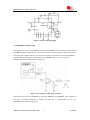
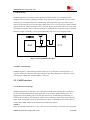
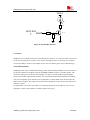
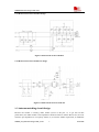
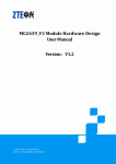
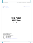
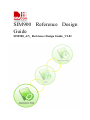
SIM900 Reference Design
Guide
SIM900_AN_ Reference Design Guide_V1.01
SIM900 Reference Design Guide Notes
Document Title:
SIM900 Reference Design Guide
Version:
1.01
Date:
2010-01-27
10Status:
Released
Document Control ID:
SIM900_AN_ Reference Design Guide_V1.01
General Notes
SIMCom offers this information as a service to its customers, to support application and
engineering efforts that use the products designed by SIMCom. The information provided is based
upon requirements specifically provided to SIMCom by the customers. SIMCom has not
undertaken any independent search for additional relevant information, including any information
that may be in the customer’s possession. Furthermore, system validation of this product designed
by SIMCom within a larger electronic system remains the responsibility of the customer or the
customer’s system integrator. All specifications supplied herein are subject to change.
Copyright
This document contains proprietary technical information which is the property of SIMCom
Limited., copying of this document and giving it to others and the using or communication of the
contents thereof, are forbidden without express authority. Offenders are liable to the payment of
damages. All rights reserved in the event of grant of a patent or the registration of a utility model
or design. All specification supplied herein are subject to change without notice at any time.
Copyright © Shanghai SIMCom Wireless Solutions Ltd. 2010
SIM900_AN_Reference Design Guide_V1.01
2
01.27.2010
SIM900 Reference Design Guide Notes
Contents
Version history..................................................................................................................................4
1. Introduction...................................................................................................................................5
1.1 References Document ..........................................................................................................5
2 Application Interface......................................................................................................................2
2.1 Power Supply Design ...........................................................................................................2
2.1.1 VBAT design ..............................................................................................................2
2.1.2 Battery Charge design ................................................................................................3
2.1.3 PWRKEY ON/OFF design.........................................................................................4
2.1.4 Reset design................................................................................................................5
2.1.5 RTC backup design ....................................................................................................5
2.2. UART interface ...................................................................................................................5
2.2.1 UART interface design ...............................................................................................5
2.3 GPIO selection .....................................................................................................................6
2.3.1 STATUS and NETLIGHT ..........................................................................................6
2.3.2 GPIO...........................................................................................................................7
2.4 Audio interfaces ...................................................................................................................7
2.4.1 Referenced circuit of headset design ..........................................................................8
2.4.2 Referenced circuit of hand free design .......................................................................8
2.5 Antenna matching circuit design ..........................................................................................8
2.6 SIM card interface................................................................................................................9
2.7 ESD protection ...................................................................................................................10
2.8 Consideration in PCB layout..............................................................................................10
SIM900_AN_Reference Design Guide_V1.01
3
01.27.2010
SIM900 Reference Design Guide Notes
Version history
Date
Version
Description of change
Author
2010-01-01
1.01
First Release
Zhou
Qiang
SIM900_AN_Reference Design Guide_V1.01
4
01.27.2010
SIM900 Reference Design Guide Notes
1 Introduction
This document describes how to design peripheral interface of SIMCOM module providing in
your application.
1.1 References Document
SN
Document name
Remark
[1]
SIM900_ATC
SIM900 AT command Set
[2]
SIM900_HD
SIM900 Hardware Specification
[3]
SIM900_EVB_UGD
SIM900 EVB User Guide
[4]
SMT MODULE
Design Guide
RF
SMT MODULE RF Design Guide
SIM900_AN_Reference Design Guide_V1.01
5
01.27.2010
SIM900 Reference Design Guide Notes
2 Application Interface
2.1 Power Supply Design
2.1.1 VBAT design
The power supply of SIM900 is from a single voltage source of VBAT which normal operating
range is form 3.4V to 4.5V. The peak working current can rise up to 2A in maximum power
transmiting period, which will cause a voltage drop. So the power supply must be able to provide
sufficient peak current, if not, the voltage may drop lower than 3.4V, and the module will auto
power down. Typically, VBAT can be set to 4V.
SIM900 can be used in a wide range of application, the power supply design is deeply depending
on the power source.
When the input is a 5V/2A adapter, a LDO linear regulator can be used in the design because the
drop out between input and output is not so big. Figure 1 is the recommended circuit with
MIC29302. Please also pay attention to the heat dissipation of the LDO. Usually, pouring a copper
plane on the PCB is an effective way to the heat sink problem of the power IC.
Figure 1: LDO Power Supply
NOTE 1:
The bypass capacitor C102 in Figure 1 is selected strongly depending on the rated current of the
power source and the power IC .If both of the rated current are 2A, a low ESR tantalum capacitor
(220uF or smaller) close to the VBAT pin is enough. Or you should change C102 to a big value
according to the practical application. The rated current should not be less than 800mA (5V
output).
The power IC and the bypass capacitor should be placed near the module, and the VBAT trace
should be routed as wide and short as possible to reduce the PCB copper resistance when layout.
When the input voltage is 12V or more high, a DC to DC converter is the best choice as its high
SIM900_AN_Reference Design Guide_V1.01
2
01.27.2010
SIM900 Reference Design Guide Notes
efficiency.
When the module is powered by a DC-DC converter, then should pay more attention to the
switching noise suppression design, otherwise the RF performance of SIM900 will be interfered
by the switching noise of DC-DC, and cause some RF performance degraded, for example,
modulation spectrum, switching spectrum will exceed the limit. As a solution, a large current
ferrite bead FB101 (0805 size package, rated current > 2A, low DC resistance ) can be added
between the DC-DC output and the VBAT in series. By default, FB101 can be mounted with a
0ohm resistor, and when need, it can be instead with a large current ferrite bead. For a typical
application in automotive, following Figure 2 shows a reference circuit.
Figure 2: DC-DC Power Supply
When the input is from the USB port of a computer, the average current is 500mA according to
the USB specification, so a super capacitor must be added near the module VBAT pins to
compensate the peak current in transmit burst. A low ESR tantalum capacitor is usually used. The
value for the capacitor should be not less than 470uF.
2.1.2 Battery Charge design
SIM900 do not support the battery charge function. When the Li-ion battery is needed in the
application, a charger IC will be implemented. If the battery is only for backup (the AC adaptor is
mostly powered), we suggest you choose a charger IC with power-path management for battery
lifespan. For example: BQ2407x series from Texas Instruments. Following figure 3 is the
reference circuit using BQ24075.
SIM900_AN_Reference Design Guide_V1.01
3
01.27.2010
SIM900 Reference Design Guide Notes
Figure 3: Battery Charge Supply
2.1.3 PWRKEY ON/OFF design
The simplest way to turn on/off SIM900 is driving the PWRKEY to a low level for 1S then release.
PWRKEY pin has been pulled up to 3V inside the module. Following figure is the recommended
connection with a NPN transistor. You can choose a GPIO of your MCU to control the POWER
ON/OFF. Please note that don’t add a capacitor on PWRKEY pin, or it may cause some
unexpected problems when power on/off process.
Figure 4: Turn on/off module using transistor
The other way to power on/off SIM900 is connecting PWRKEY and PWRKEY_OUT together. In
this way, a P-channel MOSFET is needed. The first way is recommended. In this way,
PWRKEY_OUT should be kept open.
SIM900_AN_Reference Design Guide_V1.01
4
01.27.2010
SIM900 Reference Design Guide Notes
2.1.4 Reset design
SIM900 support the reset function, when the MCU find the module is in an abnormal state,
SIM900 can be restarted by pulling the RESET pin to ground for a typical 50uS. Reset is a noise
sensitivity pin, it should be kept away from the high speed signal line (eg. clock) when layout.
This pin is internal pull up to 2.8V through a 100k resistor. So it’s not necessary to add an external
pull up resistor for stable consideration if it is not used. Please pay attention that reset is only used
in emergency situation, such as software break down, module does not response the AT command.
Reset the module continually is not recommended and it may cause some unexpected fault.
SIM900
2.8V
MCU
100K
ARM9
50uS
RESET
GPIO
Figure 5: Reset SIM900 with a MCU
2.1.5 RTC backup design
SIM900 integrates s a RTC backup interface which can be connected to a backup battery or a
capacitor. Please pay attention to the rated voltage of the battery should be 3V.The RTC current
consumption is about 2uA when the VBAT is removed.
2.2. UART interface
2.2.1 UART interface design
SIM900 integrates two UART port, one is Serial Port, and the other is Debug Port. Serial port is
for AT command with the MCU while Debug port is for firmware update and bug trace. It is
suggested to connect Debug port to an external connector for module debug consideration. If
hardware flow control is not used ,DCD、DSR can be left floating. Please refer to the following
figure. DTR can be used to wake up the module from sleep mode and RI can be used to detect a
coming call or SMS. These two should connect to GPIO of the MCU.
NOTE 3:
Please note that the UART level is 2.8V, if the level is not matching, a level shift circuit is needed.
SIM900_AN_Reference Design Guide_V1.01
5
01.27.2010
SIM900 Reference Design Guide Notes
Serial
Port Connection
DBG_TXD
DBG_TXD
TXD
DBG_RXD
DBG_RXD
RXD
GND
GND
GND
Figure 7:
UART
Figure 6:
Debug Port Connection
2.3 GPIO selection
2.3.1 STATUS and NETLIGHT
STATUS pin can be used to monitor the module state during the power on/off process. After
power up, AT command will response till the STATUS change high, and it will change low after
the module log off from the base station in a power down procedure. It can be connected to a
GPIO of the MCU.
NETLIGHT is a net status indicator. It can drive a transistor to control a LED which will blink
slowly or quickly according to different states. Please note that it can’t drive a LED directly.
Both STATUS and NETLIGHT is dedicated in SIM900, they can not be used as a GPIO for the
customer.
SIM900_AN_Reference Design Guide_V1.01
6
01.27.2010
SIM900 Reference Design Guide Notes
VBAT
510R
NETLIGH
T
4.7K
BC847
47K
Figure 8: NETLIGHT indicator
2.3.2 GPIO
SIM900 serves 12 GPIO which can be controlled by the customer. As a GPI, the status can be read
by the AT command and as a GPO, it also can be controlled by the AT command. The customer
can use this GPIO to achieve some simple control. For more detail, please refer to Document[1].
2.4 Audio interfaces
SIM900 provides a pair of differential analogy audio channel, MICP & MICN can be connected to
an electret condenser microphone directly and SPKP & SPKN can drive a 32 Ohm speaker. The
maximum output power is 96mW. If the speaker is 8 Ohm, you should add an audio amplifier
between the module output and the speaker. We recommend National Semiconductor’s LM4890.
Also, the microphone input channel can be configured to a single ended mode. In this mode, the
MICN can be left open. The negative terminal of the microphone can be connected to GND in the
customer’s board.
For adjustment, you can use AT+CMIC to set the input gain level of microphone, AT+CLVL to
change the volume of the speaker. For details, please refer to [2].
SIM900_AN_Reference Design Guide_V1.01
7
01.27.2010
SIM900 Reference Design Guide Notes
2.4.1 Referenced circuit of headset design
Figure 9: Referenced circuit of headset
2.4.2 Referenced circuit of hand free design
Figure 10: Referenced circuit of audio PA
2.5 Antenna matching circuit design
Because the module is working under 50ohm system in RF part, so, to get the best RF
performance, the SMT module’s load impedance should be tuned to 50ohm. But in fact, the most
antenna’s port impedance is not a purely 50ohm, so, to meet the 50ohm requirement, an additional
SIM900_AN_Reference Design Guide_V1.01
8
01.27.2010
SIM900 Reference Design Guide Notes
antenna matching circuit should be needed. Furthermore, to facilitate the antenna debugging and
certification testing of RF performance, we suggested the customer add a RF test connector in
series between the module’s RF port and the antenna matching circuit. The recommended antenna
matching circuit is shown as below:
GND 59
RF_IN 60
GND
61
T-Type
matching circuit
RF Test Port
J1
R4
J2
C6
R3
C5
Antenna Feed Pad
SIM900
Pi-Type
matching circuit
Figure 11: Antenna Matching Circuit
In the Figure10, the components, R4, C5 and C6 make up a pi-type matching circuit structure. If
add the optional component R3, then a T-type matching circuit structure will be made up with
another two components R4 and C5. But usually, a pi-type matching circuit is enough in antenna
tuning process. The component J2 is a RF test Port, used for conduct RF test. The traces in Bold
type must be 50 ohm impedance controlled when layout a design.
For the RF test connector, we suggested the customer use the part vended by Murata, its part
number is MM8430-2610. For detail information about this part, the customer can visit Murata’s
website: http://www.murata.com.
NOTE:For detail of RF Layout information, please to [4], SMT Module RF Design Guide.
2.6 SIM card interface
The SIM interface is powered from an internal regulator in the module. Both 1.8V and 3.0V SIM
Cards are supported. You can select the 8-pin SIM card holder. The reference circuit with 8-pin
SIM card holder illustrates as following figure.We recommend an Electro-Static discharge device
ST (www.st.com ) ESDA6V1W5 or ON SEMI (www.onsemi.com ) SMF05C for ESD protection.
The 22Ω resistor showed in the following figure should be added in series on the IO line between
the module and the SIM card for matching the impedance. The SIM peripheral circuit should close
to the SIM card socket.
The SIM_PRESENCE pin is used for detecting the SIM card. There is a 100k pull down resistor
in SIM900 module. So the R110 should not be bigger than 10K. If you don’t use the SIM card
detection function, you can let the SIM_PRESENCE pin open or connect to the GND.
SIM900_AN_Reference Design Guide_V1.01
9
01.27.2010
SIM900 Reference Design Guide Notes
Figure 12: Reference circuit with 8-pin SIM card holder
2.7 ESD protection
It is suggested that it’s better to do some ESD protection in your application to improve the ESD
character of the module, especially for the signal connecting to external interface, for example,
MIC, SPK,PWRKEY,VBAT,DBG,SIMCARD.
2.8 Consideration in PCB layout
In product’s PCB design, a good PCB layout will help the improvement of the whole product
performance, including reliability, EMC performance, etc. The following are some consideration
for referenced:
1) The power trace should be short and wide, recommended above 80mil.
2) The layout of GROUND is very important. You should keep a full ground on top layer,
and most of traces should be layout on the bottom layer, especially the audio traces,
keep a whole GROUND under the module shield.
3) The audio traces (MIC & SPK) are better to be protected with ground.
4) The ground layer (top and bottom) must be connected with many vias, especially under
the module's shield case.
5) The width of MIC traces should be 8-10mil. The width of SPK traces should be
12-14mil. The audio traces had better use difference connection and keep parallel.
6) The Layer1.Layer2 under SMT module test port should be copper keep out , layer3
should be GND;
7) The Layer2 under SMT module RF pad should be copper keep out , layer3 should be
GND;
8) The Layer1.Layer2 under RF test connector should be copper keep out, layer3 should be
GND
SIM900_AN_Reference Design Guide_V1.01
10
01.27.2010
SIM900 Reference Design Guide Notes
9)
RF trace between SMT module RF pad with the RF test connector, RF trace between RF
test connector with the antenna matching circuit, RF trace between the antenna matching
circuit with the antenna feed PAD all should be controlled to 50 Ohm
10) All layers under the antenna feed pad should be copper keep out.
11) Do not layout RF trace in orthogonal
12) When layout surface Microstrip Transmission Line or offset Stripline Transmission
Line , 3W rule should be followed, that means the distance between reference GND with
RF trace should three times more than the width of RF trace.
SIM900_AN_Reference Design Guide_V1.01
11
01.27.2010
SIM900 Reference Design Guide Notes
Contact us:
Shanghai SIMCom Wireless Solutions Ltd.
Add: Building A,SIM Technology Building,No.633,Jinzhong Road,Changning
District, Shanghai,P. R. China 200335
Tel: +86 21 3235 3300
Fax: +86 21 3235 3301
URL: www.sim.com/wm
SIM900_AN_Reference Design Guide_V1.01
12
01.27.2010