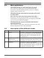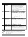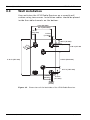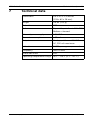
1
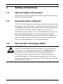
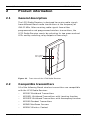
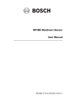
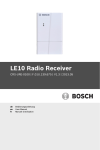
LE10 Radio Receiver
CRS-URE-0100 | F.01U.278.517 | V2.0 | 2012.11
en
User Manual
LE10 Radio Receiver
Table of Contents | en
3
Table of Contents
1
Safety instructions
5
1.1
General safety instructions
5
1.2
Environmental conditions
5
1.3
Electrostatic Discharge (ESD)
5
2
Product information
6
2.1
General description
6
2.2
Compatible transmitters
6
2.3
Main applications
7
2.4
Description of the different modes
7
3
Installation
9
3.1
Unpacking
9
3.2
Connecting the power supply
9
3.2.1
Power supply with the RJ12 power socket
9
3.2.2
Power supply connected to a wired installation
9
3.3
Wall installation
10
4
Connection compartment
11
4.1
Connecting ports
11
4.2
Mode selection
12
4.2.1
Mode indication after power on
12
5
Programming
13
5.1
Enter programming mode
13
5.2
Program a transmitter in modes 1, 2 or 5
13
5.3
Delete a transmitter
14
5.4
Delete all transmitters
14
5.5
Program a door address in modes 3 or 4
15
5.5.1
Programming in modes 6 or 7
15
6
Operation
16
6.1
Standby mode
16
6.1.1
Standby with no transmitter programmed
16
6.1.2
Standby with at least one transmitter programmed
16
Bosch Security Systems
User Manual
F.01U.278.517 | V2.0 | 2012.11
4
en | Table of Contents
LE10 Radio Receiver
6.2
Normal mode (modes 1 and 2)
6.2.1
Activation of a transmitter in normal mode
16
6.3
Dementia (mode 3)
17
6.3.1
Activation of a MIYS37L Wristband Transmitter
17
6.3.2
Detection of a MIYS37E Wristband Transmitter alone
18
6.3.3
16
Detection of a MIYS37L Wristband Transmitter with a MIYS37E
Wristband Transmitter nearby
18
Dementia with Accompany (mode 4)
19
6.4.1
Activation of a MIYS37L Wristband Transmitter
19
6.5
Remote control (mode 5)
19
6.5.1
Activation of a programmed transmitter
19
6.5.2
Activation of a programmed transmitter with a battery-low
6.4
message or with a new battery
20
6.6
Open receiver (modes 6 and 7)
20
6.6.1
Activation of a transmitter in the reception range
20
6.7
Daily messages in modes 1, 2 or 5
20
6.7.1
Daily message with battery-low signal
20
6.7.2
Reset of a battery-low indication with button T1
21
6.8
Extended MIYN46 (mode 8, only with SW 1.10)
21
6.9
Dual channel receiver (mode 9, only with SW 1.10)
22
7
Technical data
23
F.01U.278.517 | V2.0 | 2012.11
User Manual
Bosch Security Systems
LE10 Radio Receiver
Safety instructions | en
1
Safety instructions
1.1
General safety instructions
5
Installation and initial operation should only be carried out by
trained service personnel.
1.2
Environmental conditions
The LE10 Radio Receiver must not be located near a water tap
or any other source of water. The electrical safety of the LE10
Radio Receiver is only guaranteed if the electrical installation is
in accordance with the national regulations and if this
installation works properly. The LE10 Radio Receiver may not
be used in buildings prone to fire and explosion hazards.
The LE10 Radio Receiver may not be used under exposure to
direct sunlight, to heat, to dust or to an excessive humidity
(only use the equipment in a clean environment).
1.3
Electrostatic Discharge (ESD)
WARNING!
The LE10 Radio Receiver contains highly sensitive electronic
components. It should be opened only in an ESD protected
environment with respect to the following precautions.
Discharge yourself from electrostatic loads by touching a
grounded conductive surface before opening the unit. Avoid
touching conductive parts inside the LE10 Radio Receiver if not
absolutely necessary.
Bosch Security Systems
User Manual
F.01U.278.517 | V2.0 | 2012.11
6
en | Product information
LE10 Radio Receiver
2
Product information
2.1
General description
The LE10 Radio Receiver is designed to receive radio signals
from different Bosch radio transmitters at the frequency of
434.01 MHz. After receiving radio signals from either
programmed or not programmed wireless transmitters, the
LE10 Radio Receiver reacts by activating its two green and red
LEDs and by switching relay outputs of two relays.
LED 1 (green)
LED 2 (red)
Figure 2.1
2.2
Front view of the LE10 Radio Receiver
Compatible transmitters
All of the following Bosch wireless transmitters are compatible
with the LE10 Radio Receiver:
–
MIYS37 Wristband Transmitters
–
MIYS37L Wristband Transmitters with Locating function
–
MIYS37E Wristband Transmitters with Accompany function
–
MIYS35 Pendant Transmitters
–
MIYMD ManDown Sensors
–
MIYRAC Wireless Contact
F.01U.278.517 | V2.0 | 2012.11
User Manual
Bosch Security Systems
LE10 Radio Receiver
2.3
Product information | en
7
Main applications
LE10 Radio Receiver as small stand alone call system
After receiving a radio signal from a programmed radio
transmitter, the relay output switches a siren or a lamp to
indicate locally a wireless call.
LE10 Radio Receiver connected to a emergency call system
via relay contact
After receiving a radio signal from a programmed radio
transmitter, the relay will be switched. This relay output is
connected to a wired emergency call system by wire and hereby
a call will be generated or forwarded.
LE10 Radio Receiver as part of a Resident Alert System
monitoring dementia
After receiving a signal from a dementia transmitter, the relay
will be activated to close a monitored door.
2.4
Description of the different modes
Mode Name
Description
1
20 wireless transmitters can be programmed.
Normal
Calls are indicated by the red LED and Relay 1.
A battery-low signal is indicated by the red
LED and Relay 2.
2
Normal, with red LED
The same functions as in mode 1 are available,
deactivated at
except for the battery-low signal which is not
battery-low indication indicated by the red LED, but only by Relay 2.
3
Dementia
The MIYS37L and MIYS37E wireless
transmitters are detected. Relay 1 can be used
to lock a monitored door. Relay 2 can be used
to interrupt a monitoring loop.
Bosch Security Systems
User Manual
F.01U.278.517 | V2.0 | 2012.11
8
en | Product information
LE10 Radio Receiver
Mode Name
Description
4
Dementia with
This mode allows to connect the LE10 Radio
Accompany
Receiver to a wired emergency call system, in
which the Accompany function can be
implemented. It will wait 10 seconds after
receiving a signal from a MIYS37L transmitter.
If it detects a MIYS37E transmitter in this lapse
of time, no alarm is generated. If not, Relay 1 is
activated for 2 seconds.
5
Remote control
20 wireless transmitters can be programmed.
Per sequence, only the same transmitter can
switch on and off the Relay1. A battery-low
signal is indicated by the red LED and Relay 2.
6
Open receiver
No wireless transmitter needs to be
programmed. Any transmitter within reception
range of the LE10 Radio Receiver can activate
the device.
7
Open receiver with
Same functions as in mode 6, but with
reduced range
reduced range. This functionality is designed
to improve reception of transmitters located
closer to the LE10 Radio Receiver.
8
9
Extended MIYN46
Additional MIYN46 transmitters can be
transmitter
programmed. Behavior is similar to normal
programming
mode 1, with certain differences according to
(only with SW 1.10)
the transmitter that is activated.
Dual channel receiver
Only MIYS37 wireless transmitters can be
(only with SW 1.10)
programmed. Calls are indicated by Relay 1 or
Relay 2, according to the slot in which the
MIYS37 wireless transmitter is programmed. A
battery-low signal is indicated by the red LED.
NOTICE!
Factory setting is normal mode 1, in which 20 wireless
transmitters can be programmed. Calls are indicated by the red
LED and Relay 1. A battery-low signal is indicated by the red
LED and Relay 2.
F.01U.278.517 | V2.0 | 2012.11
User Manual
Bosch Security Systems
LE10 Radio Receiver
3
Installation
3.1
Unpacking
Installation | en
9
The LE10 Radio Receiver is carefully packed for transportation.
The components contained in the box are protected, but should
be handled with care. Store the packaging material for further
use (storage or transport). In case of defective or missing
equipment, do not try to install the LE10 Radio Receiver.
Contact immediately your local representative.
1. Take all components out of the box and place the LE10 Radio
Receiver on the working space.
2. Check that the following accessories are delivered: the
fixings (2 screws and 2 screw anchors) and this user manual.
3. Check that the LE10 Radio Receiver and its accessories have
not been damaged during transportation.
3.2
Connecting the power supply
There are two different ways to connect the power supply of
the LE10 Radio Receiver. After connection, the LE10 Radio
Receiver will be in standby mode.
3.2.1
Power supply with the RJ12 power socket
The LE10 Radio Receiver can be powered by a power supply
unit (PSU). The PSU should be plugged in the RJ12 socket on
the rear side of the unit and should be easily accessible at any
time. See Section 4.1 Connecting ports, page 11 for access to
the socket. See Section 7 Technical data, page 23 for
information about the power supply.
3.2.2
Power supply connected to a wired installation
The LE10 Radio Receiver can be powered by connecting a wired
input into poles 1 and 2 of the connection board. See
Section 4.1 Connecting ports, page 11 for information about the
power supply.
Bosch Security Systems
User Manual
F.01U.278.517 | V2.0 | 2012.11
10
en | Installation
3.3
LE10 Radio Receiver
Wall installation
You can fasten the LE10 Radio Receiver on a smooth wall
surface using two screws. Installation cables should be placed
inside the cable channels on the bottom.
3.4 in (80 mm)
2.2 in (53.8 mm)
0.51 in
(13.1 mm)
0.15 in
(3.7 mm)
0.63 in (16 mm)
0.26 in (6.6 mm)
n
.3 i )
Ø 0 5 mm
.
(7
1.06 in (27 mm
5.16 in (131 mm)
2.36 in (59.9 mm)
0.71 in (18.1 mm)
1.62 in
(26 mm)
0.15 in
(3.7 mm)
0.08 in
(2 mm)
Figure 3.1
F.01U.278.517 | V2.0 | 2012.11
Dimensions of the backside of the LE10 Radio Receiver
User Manual
Bosch Security Systems
LE10 Radio Receiver
Connection compartment | en
4
Connection compartment
4.1
Connecting ports
11
To open the device:
–
hold the LE10 Radio Receiver in one hand, facing you, so
that you can see the Bosch logo and the two LEDs.
–
grab the connection compartment housing with the other
hand and slide it towards you.
–
you can now see the components as in the following
illustration:
Relay 2
output
P130
ON
S3
OFF
1 2 3 4 5
6
T1
Relay 1
output
1
P133
RJ12
–
8 - 30 VDC
+
6
–
5
4
3
2
1
+
Relay 1 output
Figure 4.1
LE10 Radio Receiver connection compartment
NOTICE!
The standby conditions of Relay 1 and Relay 2 are as shown in
this illustration.
Bosch Security Systems
User Manual
F.01U.278.517 | V2.0 | 2012.11
12
en | Connection compartment
4.2
LE10 Radio Receiver
Mode selection
Modes 1 to 9 can be selected by operating switches 1 to 5 of
the 5-digits micro switch S3.
CAUTION!
After selecting the mode, disconnect the power supply and
connect it again.
Mode Description
1
2
Switch number
1
2
3
4
5
Normal mode
off
off
off
off
off
Normal mode, with the red LED
on
off
off
off
off
deactivated at battery-low indication
3
Dementia mode
off
on
off
off
off
4
Dementia with Accompany mode
on
on
off
off
off
5
Remote control
off
off
on
off
off
6
Open receiver
on
off
on
off
off
7
Open receiver with reduced range
off
on
on
off
off
8
Extended N46 (only with SW 1.10)
on
on
on
off
off
9
Dual channel receiver (only with SW 1.10)
off
off
off
on
off
NOTICE!
Factory setting is all switches set to off.
4.2.1
Mode indication after power on
–
When the power supply is connected to the LE10 Radio
Receiver, the green LED will light up permanently for 2
seconds. Afterwards, the device will display the current
mode through the green LED, by blinking as many times as
the number of the mode. The green LED will then light up
permanently.
Example: In mode 8, the green LED will blink 8 times.
–
When changing the mode, all programmed transmitters will
be deleted.
F.01U.278.517 | V2.0 | 2012.11
User Manual
Bosch Security Systems
LE10 Radio Receiver
Programming | en
5
Programming
5.1
Enter programming mode
13
To enter programming mode, press simply button T1 for the
desired time. See Section 4.1 Connecting ports, page 11.
NOTICE!
Both relays will not be activated in the programming mode.
5.2
Program a transmitter in modes 1, 2 or 5
NOTICE!
Per programming sequence only one transmitter can be
matched. You can program up to 20 transmitters.
To start programming
–
Press button T1 for min. 1 second and max. 3 seconds.
Device behavior
–
The green LED stays permanently on.
–
The red LED blinks slowly for maximum 30 seconds.
Within these 30 seconds, activate the transmitter that you want
to match, the following behavior should be observed:
–
The green LED and the red LED blink alternating for 6
seconds.
This indication confirms that the transmitter is programmed.
–
If the transmitter is already programmed, then the red LED
blinks fast for 6 seconds after activating the transmitter.
–
If 20 transmitters are already programmed, then the red
LED blinks fast for 10 seconds directly after activating the
button T1 between 1 and 3 seconds.
You can repeat the sequence with another transmitter.
Bosch Security Systems
User Manual
F.01U.278.517 | V2.0 | 2012.11
14
en | Programming
5.3
LE10 Radio Receiver
Delete a transmitter
NOTICE!
Per sequence only one transmitter can be deleted.
To start deleting:
–
Press button T1 for min. 5 seconds and max. 10 seconds.
Device behavior
–
The green LED stays permanently on, then after 5 seconds
blinks fast 5 times.
–
The red LED stays off and then blinks for 30 seconds.
Within these 30 seconds, activate the transmitter that you want
to delete, the following behavior should be observed:
–
The green LED stays permanently on.
–
The red LED stays permanently on for 5 seconds and then
turns off.
This indication confirms that the transmitter is deleted. You can
repeat the sequence with another transmitter.
5.4
Delete all transmitters
To start deleting
–
Press button T1 for minimum 20 seconds and maximum 40
seconds.
Device behavior
–
The green LED stays permanently on, then after 5 seconds,
blinks fast 5 times. After 20 seconds, the green LED will
blink for 20 seconds.
–
At that moment, the red LED lights up permanently for 5
seconds then turns off.
This indication confirms that all transmitters are then deleted.
NOTICE!
If button T1 is pressed longer than 40 seconds, then the LE10
Radio Receiver will jump out of the programming mode.
F.01U.278.517 | V2.0 | 2012.11
User Manual
Bosch Security Systems
LE10 Radio Receiver
5.5
Programming | en
15
Program a door address in modes 3 or 4
You can program a door address stored in a MIYS37L Wristband
Transmitter with Locating function, in modes 3 or 4.
NOTICE!
A door address must be stored beforehand in a MIYS37L
Wristband Transmitter with Locating function.
NOTICE!
Only one door address of a MIYS37L Wristband Transmitter
with Locating function can be matched in the LE10 Radio
Receiver.
To start programming
–
Press button T1 min. 1 second and max. 3 seconds.
Device behavior
–
The green LED stays permanently on.
–
The red LED blinks slow for max. 30 seconds.
–
Activate the S37L Wristband Transmitter, which you desire
to match, before the end of the 30 seconds.
–
Upon activating the transmitter, the green LED and the red
LED blink alternating quick for 6 seconds.
This indication confirms that the door address in the MIYS37L
Wristband Transmitter is matched in the LE10 Radio Receiver.
CAUTION!
When a new door address stored in a MIYS37L Wristband
Transmitter is programmed, it overwrites the current door
address.
5.5.1
Programming in modes 6 or 7
It is neither possible nor necessary to program a transmitter in
modes 6 or 7 (Open Receiver).
Bosch Security Systems
User Manual
F.01U.278.517 | V2.0 | 2012.11
16
en | Operation
LE10 Radio Receiver
6
Operation
6.1
Standby mode
The LE10 Radio Receiver enters standby mode when the power
supply is connected. Both relays are off. See Section 4.2.1 Mode
indication after power on, page 12.
6.1.1
Standby with no transmitter programmed
Device behavior
6.1.2
–
The green LED stays permanently on.
–
The red LED blinks 3 times every 10 seconds.
Standby with at least one transmitter programmed
Device behavior
–
The green LED stays permanently on.
–
The red LED stays permanently off.
6.2
Normal mode (modes 1 and 2)
6.2.1
Activation of a transmitter in normal mode
Device behavior
–
The green LED stays permanently on.
When a matched transmitter is activated:
–
The red LED lights up permanently for 10 seconds.
–
Relay 1 switches on for 10 seconds.
–
Relay 2 stays off.
If the same or another matched transmitter is activated within
10 seconds, the alarm will be retriggered for 10 seconds.
Device behavior when a transmitter has a low battery
–
The green LED stays permanently on.
When the transmitter is activated:
–
The red LED blinks twice for 2 seconds, then lights up
permanently for 8 seconds. It then blinks once every 10
seconds.
–
Relay 1 switches on for 10 seconds.
F.01U.278.517 | V2.0 | 2012.11
User Manual
Bosch Security Systems
LE10 Radio Receiver
–
Operation | en
17
Relay 2 switches on permanently until the battery is
replaced and the transmitter is activated again.
NOTICE!
In normal mode 2, the red LED is deactivated regarding batterylow indication and will not blink every 10 seconds.
Device behavior when the battery is replaced in a transmitter
–
The green LED stays permanently on.
When the transmitter is activated:
–
The red LED stops blinking every 10 seconds, and lights up
permanently for 10 seconds.
–
Relay 1 switches on for 10 seconds.
–
Relay 2 switches off.
6.3
Dementia (mode 3)
6.3.1
Activation of a MIYS37L Wristband Transmitter
Device behavior
–
The green LED stays permanently on.
When a MIYS37L transmitter is activated:
–
The red LED lights up permanently for 7 seconds.
–
Relay 1 switches on for 7 seconds.
–
1 second after Relay 1, Relay 2 switches on for 3 seconds.
The procedure is repeated if a MIYS37L transmitter is activated
again.
Device behavior when a MIYS37L transmitter has a low
battery
–
The green LED stays permanently on.
When the MIYS37L transmitter is activated:
–
The red LED blinks twice for 2 seconds and then lights up
permanently red for 5 seconds.
–
Relay 1 and Relay 2 behave as above.
Bosch Security Systems
User Manual
F.01U.278.517 | V2.0 | 2012.11
18
en | Operation
6.3.2
LE10 Radio Receiver
Detection of a MIYS37E Wristband Transmitter
alone
Device behavior
–
The green LED stays permanently on.
When a MIYS37E transmitter is detected:
–
The red LED lights up permanently for 30 seconds.
–
Relay 1 stays off for 30 seconds.
–
Relay 2 switches on for 25 seconds.
During these 30 seconds, all radio reception is fully blocked.
This allows a person wearing the MIYS37E to cross the
monitored area without generating an accompany signal.
6.3.3
Detection of a MIYS37L Wristband Transmitter
with a MIYS37E Wristband Transmitter nearby
Device behavior
–
The green LED stays permanently on.
When a MIYS37L transmitter and a MIYS37E transmitter are
detected by the monitored area:
–
The red LED lights up permanently.
–
Relay 1 switches on until the MIYS37E transmitter is
detected.
–
1 second after Relay 1, Relay 2 switches on for 3 seconds.
When the MIYS37E transmitter sends its signal (approx. 4
seconds after the MIYS37L):
–
The red LED lights up permanently for 30 seconds.
–
Relay 1 switches off for 30 seconds.
–
Relay 2 stays on for another 25 seconds.
After the detection of the MIYS37E transmitter, all radio
reception is fully blocked during 30 seconds. This allows a
person wearing the MIYS37E transmitter to accompany a
person wearing the MIYS37L transmitter through the monitored
area without generating an accompany signal.
F.01U.278.517 | V2.0 | 2012.11
User Manual
Bosch Security Systems
LE10 Radio Receiver
Operation | en
6.4
Dementia with Accompany (mode 4)
6.4.1
Activation of a MIYS37L Wristband Transmitter
19
Device behavior
–
The green LED stays permanently on.
When a MIYS37L transmitter is activated, a 10-second time slot
starts.
If, during these 10 seconds, a MIYS37E transmitter is detected:
–
There is no change of the LEDs and the relays.
If, during these 10 seconds, no MIYS37E transmitter is
detected:
–
The red LED lights up for 2 seconds.
–
Relay 1 switches on for 2 seconds.
–
Relay 2 stays off.
NOTICE!
In mode 4, there is no battery-low indication.
6.5
Remote control (mode 5)
6.5.1
Activation of a programmed transmitter
Device behavior
–
The green LED stays permanently on.
–
The red LED lights up.
–
Relay 1 switches on.
–
Relay 2 stays off.
When the same transmitter is activated again:
–
The red LED turns off.
–
Relay 1 switches off.
NOTICE!
No other transmitter is able to switch the Relay 1 off, when it
has been already switched on by a transmitter.
Bosch Security Systems
User Manual
F.01U.278.517 | V2.0 | 2012.11
20
en | Operation
6.5.2
LE10 Radio Receiver
Activation of a programmed transmitter with a
battery-low message or with a new battery
The behavior of the device is the same as in
Section 6.2.1 Activation of a transmitter in normal mode, page 16.
6.6
Open receiver (modes 6 and 7)
6.6.1
Activation of a transmitter in the reception range
Device behavior
–
The green LED stays permanently on.
–
The red LED lights up for 10 seconds.
–
Relay 1 switches on for 10 seconds.
–
Relay 2 switches on for 2 seconds.
Activation of any transmitter during these 10 seconds will
retrigger the procedure.
NOTICE!
In these modes 6 and 7, there is no battery-low indication.
6.7
Daily messages in modes 1, 2 or 5
6.7.1
Daily message with battery-low signal
Device behavior
–
The green LED stays permanently on.
Upon receiving a daily message with battery-low signal:
–
The red LED blinks every 10 seconds.
–
Relay 1 stays off.
–
Relay 2 switches on, until the battery is changed.
When the battery is changed, the red LED and Relay 2 switch
off if a daily message or a transmitter activation is detected.
NOTICE!
In Normal mode 2, the red LED is deactivated regarding batterylow indication and will not show any indication.
F.01U.278.517 | V2.0 | 2012.11
User Manual
Bosch Security Systems
LE10 Radio Receiver
6.7.2
Operation | en
21
Reset of a battery-low indication with button T1
Device behavior
–
The green LED stays permanently on.
–
The red LED is already blinking every 10 seconds.
Upon pressing button T1 min. 1 second, there is a reset of the
battery-low indication:
–
The red LED turns off.
–
Relay 2 switches off.
NOTICE!
If you disconnect and reconnect the power supply, the batterylow indication will be reset as well.
6.8
Extended MIYN46 (mode 8, only with SW
1.10)
Programming and deleting of transmitters is done as in Mode 1.
Standby
–
The green LED stays permanently on.
–
The red LED is off.
–
Relay 1 is switched off.
–
Relay 2 is switched off.
When a MIYS37 transmitter, MIYS35 transmitter, MIYRAC
contact, MIYMD ManDown Sensor are activated:
–
The green LED stays permanently on.
–
The red LED turns on for 2 seconds.
–
Relay 1 is switched on for 2 seconds.
–
Relay 2 is switched off.
When a MIYN46 transmitter’s red or blue button is pressed,
or when one of its inputs is activated:
–
The green LED stays permanently on.
–
The red LED and Relay 1 switch on for 6 minutes or until
the green button of the MIYN46 transmitter is pressed.
–
Relay 2 is switched off.
Bosch Security Systems
User Manual
F.01U.278.517 | V2.0 | 2012.11
22
en | Operation
LE10 Radio Receiver
NOTICE!
A MIYN46 transmitter in repeated alarm mode extends the
behavior of the LE10 by approximately 26 minutes. If several
MIYN46 transmitters are programmed, each activated
transmitter stops the sequence and starts its own sequence.
Battery-low indication:
–
Relay 2 switches on for 2 seconds.
–
The red LED flashes for 2 seconds, then blinks 1 second
every 10 seconds.
For all MIYS35 and MIYS37 transmitters, the battery low status
is triggered when the transmitter is activated or with the daily
message. For all MIYN46 transmitters, the battery low status is
triggered only with the daily message.
6.9
Dual channel receiver (mode 9, only with
SW 1.10)
Programming and deleting of transmitters is done as in Mode 1.
Standby
–
The green LED stays permanently on.
–
The red LED is off.
–
Relay 1 is switched off.
–
Relay 2 is switched off.
When a transmitter, that is matched on a odd position (1, 3, 5,
etc.), is activated:
–
Relay 1 switches on for 2 seconds.
–
The red LED turns on for 2 seconds.
When a transmitter, that is matched on a even position (2, 4,
6, etc.), is activated:
–
Relay 2 switches on for 2 seconds.
–
The red LED blinks 1 second on, 1 second off, 1 second on.
Battery low indication (until the battery is exchanged)
–
The red LED flashes during 2 seconds, then flashes 1
second every 10 seconds.
F.01U.278.517 | V2.0 | 2012.11
User Manual
Bosch Security Systems
LE10 Radio Receiver
7
Technical data | en
23
Technical data
Dimensions
5.3 x 3.2 x 1.0 inches
(133 x 82 x 26 mm)
Weight
3.9 oz (110 g)
Material
ABS
Color
Top: white, similar to RAL 9010
Bottom: charcoal
External power supply
8-30 VDC
Current consumption
< 25 mA
Outputs
2 relays, with max 28 V DC or
AC, 250 mA maximum
Indication
2 LEDs, one green, one red
Frequency
434.01 MHz
Protection class
IP21
Operating temperature range
32°F - 113°F (0°C - 45 °C)
Bosch Security Systems
User Manual
F.01U.278.517 | V2.0 | 2012.11
Bosch Security Systems
2400 Geng Road, Suite 200
Palo Alto, CA 94303
U.S.A.
www.bosch-telehealth.com
© Bosch Security Systems, 2012