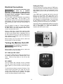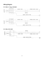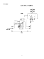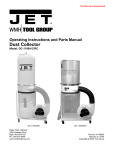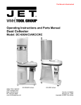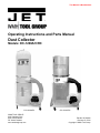
1
This Manual is Bookmarked
Operating Instructions and Parts Manual
Dust Collector
Models: DC-1200A/C/RC
DC-1200A/RC
WMH TOOL GROUP
2420 Vantage Drive
Elgin, Illinois 60123
Ph.: 800-274-6848
www.wmhtoolgroup.com
DC-1200C/RC
Part No. M-708634
Revision G 07/04
Copyright © WMH Tool Group
This manual has been prepared for the owner and operators of the JET DC-1200 Series Dust Collectors. Its
purpose, aside from machine operation, is to promote safety using accepted operating and maintenance
procedures. To obtain maximum life and efficiency from your dust collector and to aid in using it safely, please
read this manual thoroughly and follow the instructions carefully.
Warranty and Service
WMH Tool Group warrants every product it sells. If one of our tools needs service or repair, one of our
Authorized Repair Stations located throughout the United States can provide quick service or information.
In most cases, a WMH Tool Group Repair Station can assist in authorizing repair work, obtaining parts, or
perform routine or major maintenance repair on your JET product.
For the name of an Authorized Repair Station in your area, please call 1-800-274-6848, or visit our web site at
www.wmhtoolgroup.com.
More Information
WMH Tool Group is consistently adding new products to the line. For complete, up-to-date product
information, check with your local WMH Tool Group distributor, or visit our web site at www.wmhtoolgroup.com
WMH Tool Group Warranty
WMH Tool Group makes every effort to assure that its products meet high quality and durability standards and
warrants to the original retail consumer/purchaser of our products that each product be free from defects in
materials and workmanship as follows: 1 YEAR LIMITED WARRANTY ON ALL PRODUCTS UNLESS
SPECIFIED OTHERWISE. This Warranty does not apply to defects due directly or indirectly to misuse, abuse,
negligence or accidents, normal wear-and-tear, repair or alterations outside our facilities, or to a lack of
maintenance.
WMH TOOL GROUP LIMITS ALL IMPLIED WARRANTIES TO THE PERIOD SPECIFIED ABOVE,
BEGINNING FROM THE DATE THE PRODUCT WAS PURCHASED AT RETAIL. EXCEPT AS STATED
HEREIN, ANY IMPLIED WARRANTIES OR MERCHANTABILITY AND FITNESS ARE EXCLUDED. SOME
STATES DO NOT ALLOW LIMITATIONS ON HOW LONG THE IMPLIED WARRANTY LASTS, SO THE
ABOVE LIMITATION MAY NOT APPLY TO YOU. IN NO EVENT SHALL WMH TOOL GROUP BE LIABLE
FOR DEATH, INJURIES TO PERSONS OR PROPERTY, OR FOR INCIDENTAL, CONTINGENT, SPECIAL,
OR CONSEQUENTIAL DAMAGES ARISING FROM THE USE OF OUR PRODUCTS. SOME STATES DO
NOT ALLOW THE EXCLUSION OR LIMITATION OF INCIDENTAL OR CONSEQUENTIAL DAMAGES, SO
THE ABOVE LIMITATION OR EXCLUSION MAY NOT APPLY TO YOU.
To take advantage of this warranty, the product or part must be returned for examination, postage prepaid, to
an Authorized Repair Station designated by our office. Proof of purchase date and an explanation of the
complaint must accompany the merchandise. If our inspection discloses a defect, we will either repair or
replace the product at our discretion, or refund the purchase price if we cannot readily and quickly provide a
repair or replacement. We will return the repaired product or replacement at WMH Tool Group’s expense, but
if it is determined there is no defect, or that the defect resulted from causes not within the scope of WMH Tool
Group’s warranty, then the user must bear the cost of storing and returning the product. This warranty gives
you specific legal rights; you may also have other rights, which vary from state to state.
WMH Tool Group sells through distributors only. Members of the WMH Tool Group reserve the right to effect at
any time, without prior notice, alterations to parts, fittings and accessory equipment, which they may deem
necessary for any reason whatsoever.
2
Table of Contents
Warranty and Service ........................................................................................................................................... 2
Table of Contents.................................................................................................................................................. 3
Warnings ............................................................................................................................................................... 4
Introduction ........................................................................................................................................................... 6
Specifications ........................................................................................................................................................ 6
Dust Collector with Filter Bag ............................................................................................................................ 6
Dust Collector with Canister .............................................................................................................................. 6
Ordering Replacement Parts ................................................................................................................................ 6
Unpacking ............................................................................................................................................................. 7
DC-1200A/RC Dust Collector............................................................................................................................ 7
DC-1200C/RC Dust Collector ........................................................................................................................... 8
Assembly............................................................................................................................................................... 9
Base .................................................................................................................................................................. 9
Motor and Fan Assembly .................................................................................................................................. 9
Connector Housing.......................................................................................................................................... 10
Hose ................................................................................................................................................................ 10
Filter Bag Installation – DC-1200A/RC............................................................................................................ 11
Collector Bag Installation – DC-1200A/RC ..................................................................................................... 11
Collector Bag Installation – DC-1200C/RC ..................................................................................................... 12
Canister Filter Assembly and Installation – DC-1200C/RC............................................................................. 12
Electrical Connections ........................................................................................................................................ 13
Turning the Machine On & Off ............................................................................................................................ 13
DC-1200A and DC-1200C............................................................................................................................... 13
DC-1200RC..................................................................................................................................................... 13
Setting the Timer ............................................................................................................................................. 13
Maintenance........................................................................................................................................................ 14
Cleaning the Filter Bag – DC-1200A/RC......................................................................................................... 14
Removing the Collector Bag – DC-1200A/RC ................................................................................................ 14
Cleaning the Filter – DC-1200C/RC................................................................................................................ 14
Removing the Collector Bag – DC-1200C/RC ................................................................................................ 14
Motor ............................................................................................................................................................... 14
Connecting the Dust Collector to a Machine................................................................................................... 14
Grounding the Dust Collection System ........................................................................................................... 14
Parts List – DC-1200A/RC Dust Collector....................................................................................................... 15
Assembly – DC-1200A/RC Dust Collector ...................................................................................................... 16
Filter Assembly for DC-1200C/RC Models...................................................................................................... 17
Remote Control Breakdown for DC-1200RC .................................................................................................. 18
Wiring Diagram ................................................................................................................................................... 19
DC-1200A-3: 3 Phase 230V/460V .................................................................................................................. 19
DC-1200A-1/DC-1200C .................................................................................................................................. 19
DC-1200RC..................................................................................................................................................... 20
3
Warnings
1. Read and understand the entire owners manual before attempting assembly or operation.
2. Read and understand the warnings posted on the machine and in this manual. Failure to comply with all of
these warnings may cause serious injury.
3. Replace the warning labels if they become obscured or removed.
4. This dust collector is designed and intended for use by properly trained and experienced personnel only. If
you are not familiar with the proper and safe operation of a dust collector, do not use until proper training
and knowledge have been obtained.
5. Do not use this dust collector for other than its intended use. If used for other purposes, WMH Tool Group
disclaims any real or implied warranty and holds itself harmless from any injury that may result from that
use.
6. Always wear approved safety glasses/face shields while using this dust collector. Everyday eyeglasses
only have impact resistant lenses; they are not safety glasses.
7. Before operating this dust collector, remove tie, rings, watches and other jewelry, and roll sleeves up past
the elbows. Remove all loose clothing and confine long hair. Non-slip footwear or anti-skid floor strips are
recommended. Do not wear gloves.
8. Wear ear protectors (plugs or muffs) during extended periods of operation.
9. Some dust created by power sanding, sawing, grinding, drilling and other construction activities contain
chemicals known to cause cancer, birth defects or other reproductive harm. Some examples of these
chemicals are:
•
Lead from lead based paint.
•
Crystalline silica from bricks, cement and other masonry products.
•
Arsenic and chromium from chemically treated lumber.
Your risk of exposure varies, depending on how often you do this type of work. To reduce your exposure
to these chemicals, work in a well-ventilated area and work with approved safety equipment, such as face
or dust masks that are specifically designed to filter out microscopic particles.
10. Do not operate this machine while tired or under the influence of drugs, alcohol or any medication.
11. Make certain the switch is in the OFF position before connecting the machine to the power supply.
12. Make certain the machine is properly grounded.
13. Make all machine adjustments or maintenance with the machine unplugged from the power source.
14. Remove adjusting keys and wrenches. Form a habit of checking to see that keys and adjusting wrenches
are removed from the machine before turning it on.
15. Keep safety guards in place at all times when the machine is in use. If removed for maintenance purposes,
use extreme caution and replace the guards immediately.
16. Check damaged parts. Before further use of the machine, a guard or other part that is damaged should be
carefully checked to determine that it will operate properly and perform its intended function. Check for
alignment of moving parts, binding of moving parts, breakage of parts, mounting and any other conditions
that may affect its operation. A guard or other part that is damaged should be properly repaired or
replaced.
17. Provide for adequate space surrounding work area and non-glare, overhead lighting.
18. Keep the floor around the machine clean and free of scrap material, oil and grease.
19. Keep visitors a safe distance from the work area. Keep children away.
4
blahblahblah
20. Make your workshop child proof with padlocks, master switches or by removing starter keys.
21. Give your work undivided attention. Looking around, carrying on a conversation and “horse-play” are
careless acts that can result in serious injury.
22. Do not use the dust collector for anything except wood dust. Materials such as liquids, metal shavings,
metal dust, screws, glass, plastic or rock can cause sparks and/or damage when coming into contact with
any part of the dust collector.
23. Use recommended accessories; improper accessories may be hazardous.
24. Maintain tools with care. Follow instructions for lubricating and changing accessories.
25. Turn off the machine before cleaning. Use a brush or compressed air to remove chips or debris — do not
use your hands.
26. Do not stand on the machine. Serious injury could occur if the machine tips over.
27. Never leave the machine running unattended. Turn the power off and do not leave the machine until it
comes to a complete stop.
28. Remove loose items and unnecessary work pieces from the area before starting the machine.
Familiarize yourself with the following safety notices used in this manual:
This means that if precautions are not heeded, it may result in minor injury and/or possible
machine damage.
This means that if precautions are not heeded, it may result in serious injury or possibly even
death.
- - SAVE THESE INSTRUCTIONS - -
5
Introduction
This manual is provided by JET covering the safe operation and maintenance procedures for model
DC-1200 Series Dust Collectors. This manual contains instructions on installation, safety precautions, general
operating procedures, maintenance instructions and parts breakdown. This machine has been designed and
constructed to provide years of trouble free operation if used in accordance to instructions set forth in this
manual. If there are any questions or comments, please contact either your local supplier or WMH Tool Group.
Specifications
Dust Collector with Filter Bag
Model ........................................................................................... DC-1200A-1/ A-3................................DC-1200RC
Stock Number ................................................................................. 708634/708635.................................. 708634RC
Blower Wheel Diameter ...................................................................................... 12".............................................. 12”
Sound Rating at 3 feet ...............................................................................80-85 db..................................... 80-85 db
Hose Diameter .............................................................................................. 4" & 6”........................................ 4" & 6”
Air Flow (CFM) ................................................................................................ 1,200.......................................... 1,200
Velocity at 4” (FPM) ...................................................................................... 13,745........................................ 13,745
Static Pressure (inch of water)........................................................................ 11.44.......................................... 11.44
Bag Diameter ...................................................................................................... 20".............................................. 20"
Bag Length....................................................................................................31-1/2"........................................31-1/2"
Collector Bag Capacity (cu. ft.) ........................................................................... 5.6.............................................. 5.6
Overall Dimensions 30 Micron .................................................37"L x 28"W x 79"H....................37"L x 28"W x 79"H
Overall Dimensions 5 Micron ...................................................37"L x 28"W x 96"H....................37"L x 28"W x 96"H
Motor (TEFC) – DC-1200A-1 only ..........................................2 HP, 1Ph 230V only..................2 HP, 1Ph 230V only
Motor (TEFC) – DC-1200A-3 only ................ 2 HP, 3Ph 230/460V, Prewired 230V...................................................
Net Weight (approx.)....................................................................................105 lbs........................................105 lbs.
Dust Collector with Canister
Model ...................................................................................................... DC-1200C............................. DC-1200CRC
Stock Number ............................................................................................708634C.................................. 708635RC
Blower Wheel Diameter ...................................................................................... 12".............................................. 12"
Sound Rating at 3 feet ...............................................................................80-85 db..................................... 80-85 db
Hose Diameter .............................................................................................. 4" & 6” ....................................... 4" & 6”
Air Flow (CFM) ................................................................................................ 1,200.......................................... 1,200
Velocity at 4” (FPM) ...................................................................................... 13,745........................................ 13,745
Static Pressure (inch of water)........................................................................ 11.44.......................................... 11.44
Bag Diameter ...................................................................................................... 20".............................................. 20"
Bag Length................................................................................................ 45” & 28".................................... 45” & 28"
Collector Bag Capacity (cu. ft.) ........................................................................... 5.6.............................................. 5.6
Overall Dimensions 2 Micron ............................................ 37"L x 28"W x 70-7/8"H............. 37"L x 28"W x 70-7/8"H
Motor (TEFC) ..........................................................................2 HP, 1Ph 230V only..................2 HP, 1Ph 230V only
Net Weight (approx.)....................................................................................126 lbs. ......................................126 lbs.
The above specifications were current at the time this manual was published, but because of our policy of
continuous improvement, WHM Tool Group reserves the right to change specifications at any time and without
prior notice, without incurring obligations.
Ordering Replacement Parts
Replacement parts are listed in the back of this manual. To order parts or reach our service department, call
800-274-6848 between 7:00 a.m. and 6:00 p.m. (CST), Monday through Friday. Having the Model Number
and Serial Number of your machine available when you call will allow us to serve you quickly and accurately.
6
Unpacking
DC-1200A/RC Dust Collector
1. Remove all contents from the shipping carton.
2. Report any damage to your distributor.
3. Do not discard any shipping material until after
the dust collector has been assembled and is
running properly.
Contents of the Shipping Carton
1 – Upper Bag Hanger
1 – Base
1 – Housing
1 – Hanger Bracket
1 – Owner's Manual
1 – Hose
1 – Warranty Card
1 – Motor/Fan Assembly
1 – Collector Bag
1 – Filter Bag
2 – Hose Clamps
1 – Retainer Strap
4 – Casters
1 – Inlet Port & Inlet Cap
3 – Support Legs
1 – Bag of Assembly Hardware
(16) M8 x 16 Hex Cap Screws
(22) M8 Flat Washers
0(8) M6 x 12 Pan Head Flange Screws
0(6) M8 Hex Nuts
Bag of Assembly Hardware
Tools Required for Assembly
2 – 13mm Wrenches or Sockets
1 – 14mm Wrench or Socket
1 – #2 Cross Point Screw Driver
Read and understand the entire contents of this manual before attempting set-up or
operation! Failure to comply may cause serious injury.
7
Unpacking
DC-1200C/RC Dust Collector
1. Remove all contents from the shipping carton.
2. Report any damage to your distributor.
3. Do not discard any shipping material until after
the dust collector has been assembled and is
running properly.
Contents of the Shipping Carton
Canister Filter Box
1 – Canister Filter
1 – Handle
1 – Bag of Hardware for Handles
(2) M10 Hex Nuts
(2) M10 Flat Washers
(1) M10 Lock Washer
(4) Knobs
DC-1200C/RC
1 – Base
1 – Housing
1 – Owner's Manual
1 – Warranty Card
1 – Motor/Fan Assembly
5 – Collector Bags
1 – Snap Ring
2 – Ring Clamps
4 – Casters
1 – Inlet Port & Inlet Cap
3 – Support Legs
1 – Hose
1 – Bag of Assembly Hardware
(16) M8 x 16 Hex Cap Screws
(22) M8 Flat Washers
0(8) M6 x 12 Pan Head Flange Bolts
(36) M8 Hex Nuts
Bag of Hardware for Handles
Tools Required for Assembly
2 – 13mm Wrenches or Sockets
1 – 14mm Wrench or Socket
1 – #2 Cross Point Screw Driver
1 – 17mm Wrench
Bag of Assembly Hardware
Read and understand the entire contents of this manual before attempting set-up or
operation! Failure to comply may cause serious injury.
8
Assembly
Base
1. Install four casters to the under side of the base as
pictured in Fig. 2.
2. Thread the hex nut (B, Fig. 1) onto the caster
shaft. Then slide the lock washer (A, Fig. 1) over
the caster shaft. Thread the caster shaft into the
threaded hole on the underside of the base, turn
until snug. Tighten the nut (B, Fig. 1) against the
base with a 14mm wrench. This will give the
caster proper clearance.
Figure 1
Motor and Fan Assembly
3. Place the base with casters on the ground. Attach
the motor and fan assembly (A, Fig. 2) to the base
using four M8 x 16 hex cap screws, four M8 flat
washers (B, Fig. 2), and a 13mm wrench.
The dust collector must not be
connected to the power source during assembly.
Failure to comply may result in serious injury!
Figure 2
4. Attach inlet guard (A, Fig. 3) to fan housing using
eight M6 x 12 pan head screws (B, Fig. 3). Press
the inlet ports (C, Fig. 3) onto the inlet guard until it
snaps into place.
To reduce the risk of injury from
moving parts, always keep inlet port covered with
the caps provided, if they are not connected to a
hose. Failure to comply may result in serious
injury!
Figure 3
9
Connector Housing
5. Attach three support brackets (A, Fig. 4) to the
base using six M8 x 16 hex cap bolts and six M8
flat washers (B, Fig. 4). Hand-tighten only at this
time.
Figure 4
6. Install the housing (A, Fig. 5) to two support
brackets using four M8 x 16 hex cap bolts, eight
M8 flat washers, and four M8 hex nuts (B, Fig.5).
Be sure hose opening faces fan housing. Be sure
hose opening faces fan housing.
7. Before attaching third support bracket place the
hanger bracket (D, Fig.5) between the support
bracket and the housing.
Note: The hanger bracket is used in models
DC-1200A/RC only.
Tighten all nuts and bolts at this time with a 13mm
wrench.
Figure 5
Hose
8. Attach the hose (A, Fig. 6) between the fan
housing and the collector housing with two clamps
(B, Fig. 6). Tighten the clamps to secure the hose.
If you are assembling the DC-1200A/RC Dust
Collector, proceed to the next section. If you are
assembling the DC-1100C/RC Dust Collector, proceed
to Collector Bag Installation – DC-1100C/RC section.
Figure 6
10
Filter Bag Installation – DC-1200A/RC
Referring to Figure 7:
1. Place the hanger (A) on the hanger bracket (B).
2. Slide the filter bag loop (C) over the hanger hook.
3. Thread the retainer strap (D) through the loops on
the filter bag (E) and fasten to the collector
housing (F).
Figure 7
Collector Bag Installation – DC-1200A/RC
Referring to Figure 8:
4. Insert the ring (A) of the collector bag into the
bottom of the housing (B) at an angle. Pull down
on the bag to make sure it “seats” in the housing.
5. Position the plastic window in front so that you can
easily see when the collector bag is full.
After completing the filter bag and collector bag
installation, proceed to Electrical Connections.
Figure 8
11
Collector Bag Installation – DC-1200C/RC
1. Place the ring over the top of the plastic bag and
fold over the bag approximately three inches,
Figure 9.
Figure 9
2. Insert the snap ring (A, Fig. 10) of the collector
bag into the bottom of the housing at an angle.
3. Pull down on the ring to make sure it “seats” in the
housing.
Note: make sure the snap ring “snaps” into place
in the housing, and also that the plastic bag
hangs down approximately 3” so that there are no
air leaks.
Canister Filter Assembly and Installation –
DC-1200C/RC
Figure 10
4. Mount the handle onto the canister filter with two
M10 hex nuts, two M10 flat washers, and a M10
lock washer (Figure 11).
5. Mount the canister filter on top of the collector
housing (A, Fig. 5) and tighten the knobs on the
canister filter (Figure 11).
Figure 11
12
Setting the Timer
Electrical Connections
Once the machine is running, press the TIME button
to activate the timer. Each time the button is pressed
and released, the run time is incremented on the
digital display by one minute and can be set up to 99
minutes.
All electrical connections must
be
done
by
a
qualified
electrician. All adjustments or repairs must be
done with the dust collector disconnected from
the power source, unplugged. Failure to comply
may result in serious injury!
If the TIME button is pressed and held, the time will
scroll up to 99 minutes, then start again at 00.
Release the button when the desired set time is
reached. The dust collector will run for the amount of
time displayed on the digital display. If you scroll past
99 and release the button at 10, for example, the
machine will run for ten minutes, not 110 minutes.
The DC-1200A-1 and DC-1200C/RC dust collectors
are rated at 230V Only. The DC-1200C is not
supplied with a plug. Use a plug and outlet rated at
least 20amps. The circuit for the machine should also
be protected by at least a 20 amp circuit breaker or
fuse.
If the OFF button is pressed while machine is running
with the timer engaged, the machine turns off and the
timer is disengaged, i.e., when the machine is
restarted, the timer must be reset.
The DC-1200A-3 is rated at 3 Phase 230V/460V,
Prewired 230V. If you want to run the DC-1200A-3
on 460V refer to the wiring diagram found on the
inside of the switch box cover.
Keep in mind that a circuit being used by other
machines: tools, lights, heaters, etc. at the same time
will add to the electrical load. A dedicated circuit to
the dust collector will give you the best results since
dust collectors are generally used at the same time
other tools are running.
Before hooking up to the power source, make sure
that the switch is in the off position.
Turning the Machine On & Off
This machine is intended for
indoor use only.
Figure 9
Before hooking up to the power source, make sure
that the switch is in the off position.
DC-1200A and DC-1200C
Turn the DC-1200A and DC-1200C dust collectors on
by pressing the Start button mounted next to the
motor. Press the Stop button to turn off the dust
collector.
DC-1200RC
The DC-1200RC dust collectors can be controlled
from the control panel mounted on the side of the
motor (Figure 9) or from a remote control unit (Figure
10).
To start the dust collector, press the ON button. If the
remote control unit (Figure 10) is used, aim it at the
control panel (Figure 9). The machine will remain
running until the OFF button is pressed. The digital
readout will always display 00 while running.
Figure 10
13
Cleaning the Filter – DC-1200C/RC
Maintenance
Never perform maintenance on
this machine before turning switch off and
removing plug from power source. Failure to
comply may cause serious injury!
Never perform maintenance on
this machine before turning switch off and
removing plug from power source. Failure to
comply may cause serious injury!
Clean both the filter and collector bags frequently to
keep the collector's performance at its optimum.
Cleaning the Filter Bag – DC-1200A/RC
To clean the filter, turn the handle a couple of
rotations so the dust falls into the collector bag.
Wearing a particle mask or
respirator for protection against fine dust
particles during cleaning is highly recommended.
Removing the Collector Bag –
DC-1200C/RC
During first use and after cleaning, the filter bag may
allow some dust to escape. This is normal and will
stop after a short period of time.
Wearing a particle mask or
respirator for protection against fine dust
particles during cleaning is highly recommended.
Clean both the filter and collector bags frequently to
keep the collector's performance at its optimum. To
clean:
1.
2.
3.
4.
5.
1.
Disconnect the machine from the power source
outlet.
2. Remove the collector bag by pushing the ring of
the collector bag upwards at an angle and
pulling the bag and snap ring out.
3. Empty the contents into an appropriate
container.
To replace the collector bag, refer to the Collector
Bag Installation – DC-1200C/RC section.
Disconnect the machine from the power source.
Unhook the filter bag from the hanger and shake
the bag so that the majority of the dust falls into
the collector bag.
Loosen the retaining strap, and remove the filter
bag from the housing.
Turn the bag inside out and clean.
Turn the bag outside in and re-attach to the
housing using the retainer strap to secure.
Motor
Make frequent inspections of the motor fan and blow
out (with low pressure air hose) or vacuum any
accumulation of foreign material in order to maintain
normal motor ventilation.
Removing the Collector Bag –
DC-1200A/RC
1.
2.
Disconnect the machine from the power source.
Remove the collector bag by pushing the ring of
the collector bag upwards and pulling the bag
out at an angle.
3. Empty the contents into an appropriate
container.
4. Turn the bag inside out and clean.
5. Turn the bag outside in and insert into the
housing.
To replace the collector bag, refer to the Collector
Bag Installation – DC1200A/RC section.
Connecting the Dust Collector to a
Machine
Use the proper type hose to connect the dust
collector to the machine being operated. Dryer vent
hose is not acceptable for this purpose. Contact your
nearest JET distributor for the full line of JET Dust
Collector Hoses and Accessories. Customize your
installation and obtain maximum performance with
JET's dust hoods, hoses, clamps, fittings, and blast
gates.
Grounding the Dust Collection System
The dust collection system includes the dust collector
and the hose, or ductwork you use to connect the
tools. The dust collector is grounded though the
ground wire in the cord. The hose or ductwork you
use to connect the tool to the dust collector must also
be grounded. To assist in grounding your system
you can purchase the JET “Dust Collector Grounding
Kit” stock # JW1053 through JET Distributors.
14
Parts List – DC-1200A/RC Dust Collector
Index No. Part No.
Description
Size
Qty
1 ............... 411035W ................. Impeller Housing.....................................................................................................1
2 ............... 411026W ................. Motor Bracket .........................................................................................................1
3 ............... 998621..................... Strain Relief ............................................................................................................1
4 ............... MA411003 ............... Motor.....................................................................2 HP, 1Ph .................................1
................. MA411003-3 ............ Motor.....................................................................2 HP, 3 Ph ................................1
................. DC1100-50W........... Motor Fan Cover (not shown).................................................................................1
................. MF411012 ............... Motor Fan (not shown) ...........................................................................................1
................. CA003030................ Running Capacitor (not shown)............................30µf, 300V ................................1
................. CA020010................ Starting Capacitor (not shown).............................200MFD, 125VAC ....................1
5 ............... 411051..................... Switch Box..............................................................................................................1
6 ............... 411053..................... Switch Plate (DC-1200A/C only) ............................................................................1
7 ............... 994542..................... Switch (DC-1200A/C only) ...................................1 Ph ..........................................1
................. DC1900-23B............ Switch (DC-1200A/C only) ...................................3 Ph ..........................................1
8 ............... IC420002 ................. Power Cord.............................................................................................................1
9 ............... 420051..................... Motor Packing.........................................................................................................1
10 ............. AB411059................ Impeller.................................................................12” ............................................1
11 ............. 411036W ................. Inlet Guard..............................................................................................................1
12 ............. 427028..................... Inlet Port ...............................................................2 @ 4”.......................................1
13 ............. 420203..................... Inlet Cap .................................................................................................................2
14 ............. 430034..................... Inlet Flange Packing ...............................................................................................1
15 ............. 411041W ................. Base........................................................................................................................1
16 ............. 402036..................... Pivoting Caster .......................................................................................................4
17 ............. 420012W ................. Housing ..................................................................................................................1
18 ............. 402004W ................. Support ...................................................................................................................3
19 ............. 523011W ................. Hanger Bracket (DC-1200A/RC only) ....................................................................1
20 ............. 411009..................... Hose .....................................................................5”x65(CM) ................................1
21 ............. 420010..................... Ring Clamp...........................................................5” ..............................................2
22 ............. 402040..................... Hanger (DC-1200A/RC only)................................30 Micron Bag Hanger .............1
................. AB430039................ Hanger (DC-1200A/RC only)................................5 Micron Bag Hanger ...............1
24 ............. 708698..................... Filter Bag (DC-1200A/RC only) ............................30 Micron Bag ..........................1
................. 708702..................... Filter Bag (optional for DC-1200A/RC only) .........5 Micron Bag ............................1
25 ............. AB410012................ Retainer Strap ........................................................................................................1
26 ............. 708699A .................. Collection Bag (DC-1200A/RC only) ......................................................................1
27 ............. 450038..................... Bracket Cap............................................................................................................1
31 ............. ST039304 ................ Tapping Screw......................................................M3.5x12(AB) ............................6
32 ............. KS050525................ Key........................................................................5x5x25......................................1
34 ............. TS-1540061............. Hex Nut.................................................................M8 ..........................................10
35 ............. TS-0561031............. Hex Nut.................................................................3/8”-16UNC ..............................4
36 ............. TS-1490031............. Hex Cap Screw.....................................................M8x20.......................................1
37 ............. TS-1490011............. Hex Cap Screw.....................................................M8x12.......................................4
38 ............. TS-1490021............. Hex Cap Screw.....................................................M8x16.....................................16
39 ............. TS-1490041............. Hex Cap Screw.....................................................M8x25.......................................4
40 ............. TS-1554041............. Pan Head Bolt W/Flange ......................................M6x12.......................................2
41 ............. TS-1550061............. Flat Washer ..........................................................M8 ............................................1
42 ............. TS-1554041............. Pan Head Bolt W/Flange ......................................M6x12.......................................8
43 ............. TS-1550061............. Flat Washer ..........................................................M8 ..........................................34
44 ............. TS-2361081............. Lock Washer.........................................................M8 ............................................8
45 ............. TS-2361101............. Lock Washer.........................................................M10 ..........................................4
46 ............. ST059304 ................ Tapping Screw......................................................M5x12.......................................2
................. DC1200-53 .............. Grounding Label (not shown) .................................................................................1
................. DC1200-54 .............. Direction Label (not shown)....................................................................................1
................. DC1200A-NP........... Name Plate (not shown) .........................................................................................1
................. DC1100-HP ............. Hardware Package (not shown) .............................................................................1
................. DC1200A-CS........... Centrifugal Switch (not shown)...............................................................................1
................. DC1900-53 .............. Warning Label (not shown) ....................................................................................1
15
Assembly – DC-1200A/RC Dust Collector
16
Filter Assembly for DC-1200C/RC Models
Index No. Part No.
Description
Size
Qty
1 ............... 331050..................... Handle ....................................................................................................................1
2 ............... TS-1540071............. Hex Nut.................................................................M10 ..........................................2
3 ............... TS-1550071............. Flat Washer ..........................................................M10 ..........................................2
4 ............... TS-2361101............. Lock Washer.........................................................M10 ..........................................1
5 ............... BR000052................ Rivet......................................................................5-2 ............................................3
6 ............... 331014..................... Bracket ...................................................................................................................1
7 ............... 150623..................... Pad .........................................................................................................................1
8 ............... 331051..................... Soft Grip Handle .....................................................................................................2
9 ............... TS-1540041............. Hex Nut.................................................................M6 ............................................8
10 ............. 708739..................... Filter........................................................................................................................1
11 ............. 331052..................... Shaft .......................................................................................................................1
12 ............. TS-1482041............. Hex Cap Screw.....................................................M6X20 ......................................4
13 ............. TS-2361061............. Lock Washer.........................................................M6 ............................................4
14 ............. TS-1550041............. Flat Washer ..........................................................M6 ............................................4
15 ............. 331012..................... Scraper ...................................................................................................................2
16 ............. 331017..................... Strip ........................................................................................................................2
17 ............. 331015..................... Press Plate .............................................................................................................2
18 ............. TS-1482021............. Hex Cap Screw.....................................................M6x12.......................................4
19 ............. 331037..................... Knob .......................................................................................................................4
20 ............. 331031..................... Pad .........................................................................................................................1
21 ............. 331009..................... Support ...................................................................................................................1
22 ............. ST049200 ................ Tapping Screw......................................................M4X8 ........................................4
23 ............. 331038..................... Snap Ring...............................................................................................................1
24 ............. 709563..................... Plastic Bag..............................................................................................................5
17
Remote Control Breakdown for DC-1200RC
Index No. Part No.
Description
Size
Qty
................. DC1200RC-100 ....... Receiver Assembly (Items 1-12) ............................................................................1
1 ............... DCRC-101 ............... Label .......................................................................................................................1
2 ............... DCRC-102 ............... Counter Screw........................................................................................................3
3 ............... DCRC-103 ............... Switch Plate............................................................................................................1
4 ............... DCRC-104 ............... Seal.........................................................................................................................1
5 ............... DCRC-105 ............... Digital Switch ..........................................................................................................1
6 ............... DCRC-106 ............... Circuit Board...........................................................................................................1
7 ............... DCRC-107 ............... Fuse......................................................................250V, 1A...................................1
8 ............... DCRC-108 ............... Switch Box..............................................................................................................1
9 ............... CA003030................ Running Capacitor................................................30µf, 300V ................................1
10 ............. CA020010................ Starting Capacitor.................................................200MFD, 125VAC ....................1
11 ............. DCRC-111 ............... Tapping Screw......................................................M3.5x10....................................1
12 ............. ST039304 ................ Tapping Screw......................................................M3.5x12....................................6
13 ............. DCRC-113 ............... Remote Control ......................................................................................................1
14 ............. ................................. Battery ..................................................................AAA ..........................................2
18
Wiring Diagram
DC-1200A-3: 3 Phase 230V/460V
DC-1200A-1/DC-1200C
19
DC-1200RC
20