1
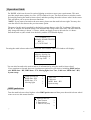
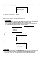
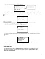
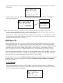
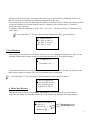
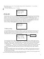
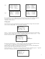
Dr. DMX II
USER'S MANUAL
24 – 004 – 1423
Rev 1.0 October 2004
Web site: www.elationlighting .com
E-mail: [email protected]
_General Information
Introduction
Thank you for purchasing the Dr. DMXII.
The Dr. DMXII features stylish design, versatility and a highly competitive price tag. The multiselector wheel can be used to select the 8 mainly menus. You can also test the DMX packet and
cable, which will catch whether there are errors. The received DMX data can also be displayed
and transmitted, complying with the your settings. If you would like to know more, please read
the user's instruction carefully, and keep it for future reference.
Unpacking
This unit has been thoroughly tested and carefully packed. Please check contents and packing
carefully to be sure that your product is not damaged and all accessories are accounted for. If your
product happens to be damaged or missing parts, please do not use it. Please contact
Elation Professional.
Safety Instructions
To reduce the risk of electric shock or fire when using this unit:
Do not immense in or expose to water.
Turn off the unit, if it will not be used for a long time.
Do not use in the event of a malfunction.
Do not dismantle or modify the unit.
_Specifications
Model No:
Power Input:
Dr..DMXII
DC 9v, 500mA
(An AC ~ DC adaptor included or
built-in chargeable battery)
DMX In:
3 and 5 pins male XLR connectors
DMX Out:
3 and 5 pins female XLR connectors
MIDI In:
5 pins Multi connector
Dimensions:
200_160_55 mm
Weight:
1.2 kg
All rights reserved. No part of this manual may be reproduced in any form or by any
means without written permission.
Customer Support:
Elation® provides a customer support line, to provide set up help and to answer any question should you
encounter problems during your set up or initial operation. You may also visit us on the web at
www.elationlighting.com for any comments or suggestions. For service related issue please contact
Elation®. Service Hours are Monday through Friday 9:00 a.m. to 5:00 p.m. Pacific Standard Time.
Voice:
(323) 582-3322
Fax:
(323) 582-3108
E-mail:
[email protected]
1
_Operation Guide
Dr. DMXII, which can be used in various lighting occasions to meet your requirements. This unit
provides ample menu options in a 20 x 4 LCD window for you. The desired menu or window can be
activated by turning the multi-selector wheel, and then pressing the multi-selector wheel in the center.
This will allow you to access the menu functions.
NOTE: If you want to forward to the next menu, please turn the multi-selector right. You may also
turn the wheel left to browse the previous menu option.
The power for this unit is supplied by the built-in storage battery or the DC 9v adaptor. When using
the DC 9v adaptor, the built-in battery will automatically charge at the same time. The time taken to
fully charge the battery is about 3~5 hours, which can supply power to this unit for 6~8 hours.
Switch the unit on, (the switch is on the back), and the LCD should display:
< ==== Elation ====
Dr.DMX–II DMX TESTER
REV1.1
( C ) NCW 2003 >
Pressing the multi-selector wheel will access the first window. The LCD window will display:
Tester hardware and
software develop by
NCW (Holdings) Ltd .
05–Apr–2003 >
You can also forward to the main window of information by using the multi-selector wheel.
If you continue to forward, there are 8 main menu options for your choice, including DMX packet
test, DMX data––RX, DMX data––TX, Moving light, Save Cue , Cable test, MIDI data––RX,
System setup.
< DMX special test
DMX data––RX
DMX data––TX
_ Moving light
>
>
>
>
_ Save Cue
?
Cable test
MIDI data -- RX
System setup
_ DMX packet test
Turn the multi-selector wheel right to select DMX packet test and then press the multi-selector wheel
center to access this menu function.
< DMX packet test:
1. Data format
2. Data timing
3. Data level (Volt)
>
>
>
_
.
2
If there is no signal input and you have accessed each menu of Data format, Data timing, Data level (Volt)
by the multi-selector wheel, the LCD window will display:
< DMX packet test:
Receive no signal
?
You may move the cursor to the “?” for help.
If there is a input signal, you can do some DMX packet tests.
1. Data format
Turn the multi-selector wheel to select Data format and press it to view the total channels of
the external operator and the states of BREAK when receiving the signals.
The LCD window shows the channel information of the external connected DMX operator.
(For example, here the connected controller is a DMX Operator.)
< Data format:
?
means: the total channels
of the DMX Operator
RX-Chan: 192
Break: --OK-Signal present
To know more, you may enable the help function by using the multi-selector.wheel. Help
information can be given as follows.
< Data format :
Indication of --OK-means: Received
signal is good
To return to the previous menu, place the cursor on “<“ and press the multi-selector wheel.
< DMX-512 tester help
No signal or signal
not complying with
USITT DMX-512( 1990 )
2. Data timing
Turn the multi-selector wheel to select Data timing and press the center to select. You can now
view all the parameters of the received signals, including BREAK, MaB, START CODE,
CHAN TIME, Period Time. The LCD window will display the data timing information.
3
(Here the connected controller is a DMX Operator.)
< Data timing:
?
BK: 135_S MaB: 016_S
StartCode : 000 dec
Chan. Time: 053_s >
All the parameters
can be shown here.
signal is good
Select “>” first and then press the multi-selector this will allow you to shift from the Chan. Time to
Period Time. In this case, the fourth line of the LCD window displays " Period: 036 ms ".
You may select the help function by using the multi-selector. Help information will be given as
follows.
< 2. Data timing :
Break min. 88_s
MaB min. 8_s
Chantime min. 44_s
3. Data level (Volt)
Turn the multi-selector wheel to select Data level (Volt) and press the center to select.
The LCD window will display the signal voltage.
(Here the external connected controller is a DMX Operator.)
< Data level (Volt) ?
--good-->
________________
Level = 4.44 V
You may select the help function by using the multi-selector. Help information will be given as
follows.
< 3. Data level
Reception may still
be possible with
lower level.
To select another menu turn the multi-selector wheel backward to return. Then select the new
entry pressing the center of the multi-selector wheel.
_ DMX data -- RX
Turn the multi-selector wheel to DMX data--RX and then press the center of the multi-selector
wheel to access this menu. There are 3 sub-menu options, including Barchart display, Value
display and Min/max display.
4
< DMX data RX
1. Barchart display
2. Value display
3. Min/ max display
>
>
>
This DMX data--RX function can display the value of the signal input by the means of a Barchart,
Value, or Min/max, complying with the display mode that can be adjusted in the System setup menu.
There are two display modes: Normal and Hold Mode.
In the Normal display mode, when pushing the fader relative to the specific channel of the external
Operator, the channel value in the LCD window will change temporarily, changing with the position
of fader.
In the Hold display mode, pushing the fader corresponding to the specific channel of the external
operator, the channel value in the LCD window may not change temporarily. The display value is
the max. value of all the adjustment of the fader.
1. Barchart display
Turn the multi-selector wheel forward to enter the Barchart display menu. If there is no signal input,
the LCD window will show empty information, for example:
Total channels of
received signal: 000
< RX Channel : 000 ?
> 001 : xxxxx xxxxx
Means: no signal
input from channel
1 to channel 10
011 : xxxxx xxxxx
021 : xxxxx xxxxx
Each line can indicate the values of 10 channels. To display the values of other
channels, turn the multi-selector wheel forward to select “>” , then press the center of the multiselector wheel. At this time you can turn the multi-selector wheel backward or forward.
On the contrary, if there is a signal input, the LCD window will display the values of the received
signals in the bar chart diagram.
< RX Channel : 192 ?
> 001 :
011 :
021 :
To know more details about the bar chart diagram, you may select “?” for help.
Here is the help information that will be given.
Each bar chart indicates the
different value of the faders.
< 1. Barchart display
chan level
x = no signal
– = no data
5
2. Value display
This option can display the value of the signal input by the means of decimal, hexadecimal and percent.
Turn the multi-selector wheel forward to enter the Barchart display option. If there is no signal input,
the LCD window will display:
< RX Channel 1 : 000 ?
Start Channel : 001 >
--- --- --- --- --> --- --- --- --- --The default total of channels is set at 000 and the start channels always automatically preset to be
001. If you would like to change the start channel, turn the multi-selector wheel to select “>” at
the right side of the LCD window. You can scroll to the desired channel No., and then press the
multi-selector wheel again to confirm.
On the contrary, if there is signal input, the LCD window will display the values of the received
signals as in the following diagram. For example:
< RX Channel: 192 ?
Start Channel: 001 >
253 255 255 000 000
> 000 000 000 000 000
For decimal, hexadecimal or percent display mode, you can turn the multi-selector wheel to select
“>” at the left side of the LCD window. And then press the center of the multi-selector to scroll to
the desired mode. The display values of the relative channels will temporarily be changed according
to the new setting.
NOTE: Other main display values of this unit may be converted, to comply with the new display
mode.
To You may activate the help function by the using the multi-selector wheel. Help information will
be be displayed as follows.
< 2. Value display
Display ten number
in decimal, hexadecimal or percent
3. Min / max display
253 255 255 000 000
> 000 000 000 000 000
The values can be displayed in a simple way, using this option, it can be displayed in min. value,
typical value, max. value. The values will comply with the decimal, hexadecimal or percent
display mode depending what mode you have set.
6
Supposed that you have set the percent display mode. If there is no signal input, the LCD window
will display.
< RX Channle : 000
Chan. min typ max
>001 --- --- --- %
>Count at : xxxxx Sec
253 255
255 000
000 the LCD window will display the
On the contrary, if the signal input is being
received
correctly,
> 000 000 000 000 000
following information.
Total channels
< RX Channle : 192
Chan. min typ max
Time counter
>001 000 28 70 %
for reference.
>Count at : 00010 Sec
253 255 255 000 000
> 000 000 000 000 000
Note: The min value display is the min. value of all the adjustments referring to the present
channel; the typ value display is the set value of the present channel; the max display is the max.
value of all the adjustments referring to the present channel.
To browse the value of each channel, turn the multi-selector to select “>” at the third line of LCD
window, then press the multi-selector. At this time you can browse the desired channel by turning
the multi-selector backward or forward.
_ DMX data -- TX
When switching on this unit, the receiving DMX signal can be transmitted automatically, with the
STARTCODE you have set. Suppose that you aren't in this DMX data--TX menu now and there
is no DMX signal input, if you have run the specific saved cue just now , the cue will be transmitted
repeatedly. In this case the new DMX signal will have first priority to be transmitted. However,
when accessing the Cable Test or MIDI data-RX menus, the transmitting signal will be stopped.
While accessing this DMX data--TX menu, the incoming DMX signal will be disabled. You will be
allowed to temporarily set the levels for the intended channels, and also have the ability to transmit
the cue (scene) at a set rate. Remember there are only 15 cues available.
Turn the multi-selector to select DMX data--TX and then press the multi-selector to access this menu
function. There are 4 sub-menu options, including 512 Channel, Single Channel, Cue/Memory,
Run Cues ( Scenes ).
1. 512 Channel
This option can display the levels of 512 channels, and also be used for temporary adjustments,
while the actual channel value can be held. When using the multi-selector to enter this sub-menu,
the LCD window usually will display:
< 1. 512 Channel
?
Mode : Modify mode
Chan : 001
_ Data : 000 = 000 %
>
>
7
To adjust the temporary value of the desired channel, first turn the multi-selector wheel to “>” at
the third line. Then adjust the "Data" at the fourth line. The "Data" displays the value by the means of
decimal and percent.
You may turn the multi-selector to scroll to the next page. The LCD window shows the values of 10
channels as in the following diagram.
Channel 3 Channel 4
Channel 1
Channel 2
_ Channel : > [ 001 -- 010 ]
000 000 000 000 000
000 000 000 000 000
Clear All
>
Channel 1
Channel 10
You can set the values of 10 channels ( 001 -- 010 ).For example, set one channel level. Locate
the cursor to the desired channel, press the multi-selector to select it.Then turning the multi-selector
to adjust the level. When satisfied with your adjustment, press the multi-selector again to confirm the
settings.
You may also adjust the other 502 channels levels. Move the cursor to “>” at the first line of LCD,
press the multi-selector and turn it to the desired channel to make for new settings. Remember
that there are only 10 channels available for your adjustments every time.
If you would like to set these 512 channels to 000, use the Clear All function by pressing the “>”
at the fourth line.
Locate the label “?” or more details. Help information can be given as follows.
< 1. 512 Channel
Modify = Each
channel will hold
its preset value
2. Single Channel
Turn the multi-selector to select the Single Channel option. You can adjust the speed, channel, mode,
and level when using this function. The speed value can be increased from 1 to 10. And there are
5 modes for reference, including Fade Only, Fade Fine, Auto On/ Off, Ramping, Stop.
Fade Only: Changes the channel value using only the fader.
Fade Fine: Based on the initial channel value by the fader at present, pushing the fader can increase the
value one by one. When the incremented value has reached 31, pushing the fader will
change the channel value into the initial value.
Auto On/Off: The channel value will be changed between 000 and 255, complying with the speed.
Ramping: The channel value will steadily increase one by one till it reaches 255, complying with the
speed. Then repeat the sequence 0 to 255.
Stop : The channel value can not be changed and will be on hold.
The LCD window will usually display the following diagram.
< Auto Speed : 01 >
Chan: 001
Mode: Fader Only
Level: 000 = 000 %
?
>
>
>
8
The Speed can will only take effect when the mode is set to Auto On/Off or Ramping. In this case,
the level of the desired channel is adjusted automatically by this unit.
You can adjust the level by the fader when the mode is set to Fader Only or Fader Fine. However, there
is only one channel level varied from the other 511 channel levels. And the other 511 channel
levels can only be the same.
In addition, when the channel is set to be " 001 - 512 ( all ) ", you can set all the 512 channels to the
same values.
Locate the label “?” for more details. Help information will be given as follows.
< 2. Single Channel
512 data is same, or
one data is special
the other is zero
3. Cue/Memory
This option can transmit the received data and save it as cues. Remember that there are only 15 Cues
available. When turn the multi-selector to select this function, the LCD window displays:
< 3. TX data as Cue ?
Cue number: 001 >
To transmit data and save is as the desired cue, turn the multi-selector to select the cue, then press the
multi-selector again to confirm. The cue will automatically be transmitted.
Locate the label “?” for more details. Help information will be given as follows.
< The 512 data of cue
4. Run Cues (Scenes)
come from RX or from
old cue which can be
modified in ‘TX-512’
Turning the multi-selector to select Run Cues (Scenes) , you can transmit cues continually at
a specific rate. When accessing this option, the LCD window will show the following diagram.
< 4. Run Cues (Scenes) ?
Total Cue: 1
End Cue 15 >
Speed rate: 01 >
Default End Cue No.
Default Speed rate
9
The default start cue is cue 1. You can adjust the end cue No. and speed rate ( 1 -10 ) by using
multi-selector wheel.
For more information, press “?” for help.
< 4. Run Cues(Scenes)
_ Moving light
From cue 1 to the
end cue continually
in speed rate
Turn the multi-selector to select Moving light and then press the multi-selector to access this menu
function. There are 2 sub-menu options, including Library setting, and Play mode. You can set the
function of each fixture channel, complying with the present library. The library of this unit is
preset to meet your requirements in general. If you would like to use your own library, please mail
us an attachment of this information for update. For more tests, in the Play Mode you can use the
library settings and adjust the parameters of relative channels for this purpose.
After accessing the Moving light, the LCD window will usually display:
< Moving light :
1. Library setting
2. Play mode
>
>
1. Library setting
To set the lighting function of the desired channel, you can use the multi-selector wheel to access
this option. The LCD window will show the fixture number, name and function of each channel.
Remember that there are only 36 channels and 10 kinds of fixtures in all, which can be set. And
each channel has 29 effect functions to be selected.
Library stored
< 1. Library setting
>
FX No : 01 NAME_1 >
01 Color 02 Cyan
03 Dimmer 04 Effect
You can adjust the fixture number, name and function of each channel by using the multi-selector.
If you would like to save your new settings, press “>” at the first line of the LCD window, the label
will display "Library stored". Pressing the multi-selector again can save the present fixture settings.
To change the fixture name, move the cursor to the “>” and press the multi-selector . The label
“>” will change to “_” , then you can locate the desired characters and press the multi-selector. Label
“_” will appear, then you can enter a new character by turning the multi-selector. Press the multiselector to confirm your setting. Repeat the procedures for the adjustment of any other characters
you desire.
To change the lighting function of the desired channel, e.g. channel 1. First locate the cursor nest to
01 and press the multi-selector. Then turn the multi-selector to the right lighting function and press
the multi-selector to confirm.
You can turn the multi-selector to browse the functions of other channels. The next four pages can be
accessed by turning the multi-selector and will display as follows:
10
fig.1
fig.3
05 Focus fig.2
06 Frost
07 Gobo 08 Gobo rot
09 Inten'ty 10 Iris
11 Lamp 12 Magenta
21 Speed P 22 Speed PT
23 Speed T 24 Strobe
25 Tilt fig.426 Tilt Fine
28 Zoom
27 Yellow
13 Pan
15 Prism
17 Rot spel
19 Special
14 Pan fine
16 Reset
18 Shutter
20 Speed CG
29 --------31 Laser
33 Color
35 Dimmer
30 -------32 Dimmer
34 Cyan
36 Effect
If you would like to set the lighting function of this unit for testing the other lighting equipment,
pay attention to the relative channels parameters of them. What you have set must be
complying with the devices.
2. Play mode
In this function you can test the fixtures by using the previous library settings. Turn on the multiselector and select Play mode . The LCD window will display:
< 2. Play mode
FX No.: 01 NAME_1
Start address: 001
Func: Color > 000
>
>
>
Locate “>” at the second line and turn the multi-selector. Now you can select the set fixture name.
The relative library settings can be available. Complying with the fixture channel, locate “>” at the
third line and turn the multi-selector to set the right start address.
< 2. Play mode
FX No : 01 NAME_1
Start address: 001
Func: Color > 000
>
>
>
Part 2
Part 1
For some tests, first locate the “>” at the “part [1]” to select the desired function. Then locate the
“>” at the “part [2]” to adjust the level by turning the multi-selector wheel.
Suppose that the start address is assigned to 001 and the function is set to Pan. Then change the
level. The fixture arms will rotate horizontally at your desire.
Another option, press “<” this gives you access to the previous menu. Continue to press “<” again for
main menus. Turning the multi-selector can display the other 4 main menus.
_ Save Cue (Scene) ?
Cable test
MIDI data -- RX
System setup
>
>
>
11
_ Save Cue ( Scene )
If there is DMX input signal present, the saved cue can be the received signal. However, if there is no
signal input, activating the Save Cue function will save the previous received or running cue as new
one. You can access the 512 channel of DMX data--TX menu to set the values of the
desired channels or modify the existing cue, and then activating the Save Cue can save the
settings as a new cue.
When accessing this menu, the LCD window will ask you for the cue number to be saved.
< Save Cue (Scene) ?
as Cue no. : 001
confirm
>
>
The default cue no. is preset to be 001. You can change the default cue number to your desired
number. First locate “>” at the second line and turn the multi-selector. To save the received data,
move the cursor to “>” at the third line to confirm. Otherwise, save the received data and the cue
number will increase by 1 for the next saving.
NOTE: After you have located “>” at the second line, turning the multi-selector can allow you to
select the " Clear all Cues ". When you confirm this function, the LCD window will ask you
" Be sure ? Yes > No > " at the fourth line . Press the first label “>” to confirm, all the stored
cues will be cleared. If you do not want to clear the cues, press the second label “>” to quit.
For more information, press “?” for help.
_ Cable test
< Save Cue ( Scenes )
The cue with 512 data
can be stored to
memory or clear cues.
When this function is activated, you can test the cable whether there are errors or not. The cable can be
tested for digital and analog mode. After accessing this menu, this a message should appear:
< Analog cable test >
Connect cable to
both sockets, press
Start ! >
The default test mode is analogy mode. To select the digital mode, turn the multi-selector to “>” at the
first line, pressing the multi-selector will allow you to activate the digital mode. Use the standard
DMX In/Output of this unit for connecting the cable. One head for female plug-in, another head for
male plug-in. Then press “>” at the fourth line to start the test. If the cable works normal, the LCD
window should display:
< Cable Test --Result successful !
- > TEST OK !
12
Otherwise, if the cable does not work normally, the LCD window displays:
< Cable Test --Result:
-> Cable not OK
_ MIDI data -- RX
This option tests the MIDI data to find out whether there are some errors when transmitting.
When the cable isn't connected normally and you have accessed this function, the LCD
window will display:
< MIDI data -- RX
$
However, if there are signal inputs and no errors, the LCD window will display:
< MIDI data -- RX
$ FE FE FE FE FE FE
FE 43 00 45 00 FE
90 43 00 FE FE FE
FE means:
NULL signal
_ System setup
In this menu you can set the system settings. There are three sub-menus for you to choose from,
including DMX setting, Language, Display setting. You can set the DMX display mode,
value display mode, and so on.
Turn the multi-selector to System setup and press it to activate this function. The LCD window should
show the following.
< System setup :
1. DMX setting
>
2. English
>
3. Display setting
>
1. DMX setting
Turn the multi-selector to DMX setting and press it, and the LCD window should display:
< Start code TX : 000
Display: Normal
Input Pin : + 2 : _3
?
Confirm
>
>
>
>
You can now set the start code for 512 DMX signal transmissions. Generally, you don’t need to
adjust it. The default of start code is set to 000. If you would like to change it, make use of the
multi- selector for this purpose.
There are two display modes: Normal and Hold Mode, as mentioned in the DMX data -- RX.
In the Normal display mode, when changing the value referring to the specific channel of the external
13
operator, the channel value of the unit will change instantly, adjusting with the position of the fader.
In the Hold display mode, when changing the value referring to the specific channel of the external
operator, the channel value of the unit may not change temporarily. The display value is
only the max. value of all the adjustments of the fader.
Turn the multi-selector to > at the second line, pressing it will shift the display mode between
Normal mode and Hold mode.
You can also use the multi-selector to shift input pin between +2 -3 and -2 +3. However,
this adjustment will comply with the receiving signals, which can be normal or reverse.
Enable the label > at the fourth line to save all the settings by the multi-selector. Or, return to the
previous menu without saving by enabling the label < .
For more information, press “?” for help.
< 1. DMX setting
Startcode TX : 00-FF
Display Hold mode
Input normal : -2 +3
2. English
This unit supports 5 languages for convenient operation, including English, German, Spanish,
French, and Italian. The default is English. Only by turning the multi-selector to choose the
desired language version, and then pressing the multi-selector to confirm, will your be allowed to
adjust the system language temporarily.
When charging this unit next time, if you want the adjustment to be available still, you must store
the adjustment. To store it, you can scroll to the DMX setting or Display setting sub-menus and select
the “confirm” item. Press the multi-selector to activate the storing function.
Note: After you have chosen your desired language, all the windows and menus of this unit
will follow this adjustment and be the language version interfaces. When switching this
unit again the stored setting will also be valid.
3. Display setting
In this sub-menu you can adjust the contrast level of the LCD window by using the multi-selector. The
default level is 05 and it ranges from 01 to 10.
< Contrast_ level: 06
Back Light: off
Display: percent
?
Confirm
>
>
>
>
To change the state of the backlight, move the cursor to “>” on the second line. Pressing the
multi-selector can turn on the back light, while pressing it again will make the back light go out.
14
NOTE: If you don’t deactivate the backlight, it will automatically go out in 10 seconds so that
it does not consume power.
You can also change the value display in three modes, including decimal, hexadecimal and percent.
To save what you have set, move the cursor to “>” on the fourth line, confirm by pressing the
multi-selector. If you don’t want to save it, move the cursor to “<” to return the previous menu.
For more information, press “?” for help.
< 3. Display setting
Contrast_level : 1-10
Back Light : On./Off
dec, hex or % data
15