1
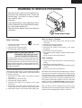
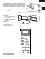
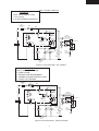
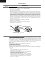
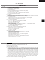
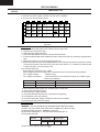
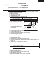
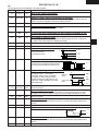
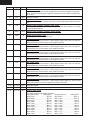
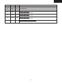
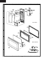
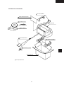
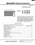
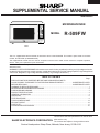
R- 509FW
SUPPLEMENTAL SERVICE MANUAL
S22M183R509FE
MICROWAVE OVEN
MODEL
R-509FW
R-509FW
This is a supplemental Service Manual for Microwave Oven model R-509FW. This model is quite similar to the base
models; R-510FK/FW (S12M182R510FE).
This supplemental manual must be used in conjunction with the base model service manual for complete operation,
service, safety and replacement parts information.
In the interest of user-safety the oven should be restored to its original condition and only parts identical to those specified
should be used.
WARNING TO SERVICE PERSONNEL: Microwave ovens contain circuitry capable of producing very high voltage and current,
contact with following parts may result in a severe, possibly fatal, electrical shock. (High Voltage Capacitor, High Voltage Power
Transformer, Magnetron, High Voltage Rectifier Assembly, High Voltage Harness etc..)
TABLE OF CONTENTS
Page
PRECAUTIONS TO BE OBSERVED BEFORE AND DURING SERVICING TO
AVOID POSSIBLE EXPOSURE TO EXCESSIVE MICROWAVE ENERGY ................... INSIDE FRONT COVER
BEFORE SERVICING ...................................................................................................... INSIDE FRONT COVER
WARNING TO SERVICE PERSONNEL ................................................................................................................ 1
MICROWAVE MEASUREMENT PROCEDURE .....................................................................................................2
FOREWORD AND WARNING ................................................................................................................................3
PRODUCT SPECIFICATIONS ............................................................................................................................... 4
GENERAL INFORMATION ...................................................................................................................................4
OPERATION .........................................................................................................................................................6
TEST PROCEDURE .............................................................................................................................................. 8
TOUCH CONTROL PANEL .................................................................................................................................. 12
CPU UNIT CIRCUIT ............................................................................................................................................. 16
PARTS LIST ........................................................................................................................................................ 17
PACKING AND ACCESSORIES ......................................................................................................................... 21
SHARP ELECTRONICS CORPORATION
This document has been published to be used for after
sales service only.
The contents are subject to change without notice.
Service Headquarters: Sharp Plaza, Mahwah, New Jersey, 07430-2135
R-509FW
PRECAUTIONS TO BE OBSERVED BEFORE AND
DURING SERVICING TO AVOID POSSIBLE
EXPOSURE TO EXCESSIVE MICROWAVE
ENERGY
(a) Do not operate or allow the oven to be operated with the door open.
(b) Make the following safety checks on all ovens to be serviced before activating the magnetron or other
microwave source, and make repairs as necessary: (1) interlock operation, (2) proper door closing, (3)
seal and sealing surfaces (arcing, wear, and other damage), (4) damage to or loosening of hinges and
latches, (5) evidence of dropping or abuse.
(c) Before turning on microwave power for any service test or inspection within the microwave generating
compartments, check the magnetron, wave guide or transmission line, and cavity for proper alignment,
integrity, and connections.
(d) Any defective or misadjusted components in the interlock, monitor, door seal, and microwave generation
and transmission systems shall be repaired, replaced, or adjusted by procedures described in this
manual before the oven is released to the owner.
(e) A microwave leakage check to verify compliance with the Federal Performance Standard should be
performed on each oven prior to release to the owner.
BEFORE SERVICING
Before servicing an operative unit, perform a microwave emission check as per the
Microwave Measurement Procedure outlined in this service manual.
If microwave emissions level is in excess of the specified limit, contact SHARP
ELECTRONICS CORPORATION immediately @1-800-237-4277.
If the unit operates with the door open, service person should 1) tell the user
not to operate the oven and 2) contact SHARP ELECTRONICS CORPORATION and Food and
Drug Administration's Center for Devices and Radiological Health immediately.
Service personnel should inform SHARP ELECTRONICS CORPORATION of any certified unit
found with emissions in excess of 4mW/cm2. The owner of the unit should be instructed
not to use the unit until the oven has been brought into compliance.
R-509FW
WARNING TO SERVICE PERSONNEL
Microwave ovens contain circuitry capable of producing very high voltage and current, contact with
following parts may result in a severe, possibly
fatal, electrical shock.
(Example)
High Voltage Capacitor, High Voltage Power Transformer, Magnetron, High Voltage Rectifier Assembly, High Voltage Harness etc..
Read the Service Manual carefully and follow all
instructions.
Don't Touch !
Danger High Voltage
When the testing is completed,
1. Disconnect the power supply cord, and then remove
outer case.
2. Open the door and block it open.
3. Discharge high voltage capacitor.
4. Reconnect the leads to the primary of the power
transformer.
5. Reinstall the outer case (cabinet).
6. Reconnect the power supply cord after the outer case is
installed.
7. Run the oven and check all functions.
Before Servicing
1. Disconnect the power supply cord
remove outer case.
2. Open the door and block it open.
3. Discharge high voltage capacitor.
, and then
WARNING:RISK OF ELECTRIC SHOCK.
DISCHARGE THE HIGH-VOLTAGE
CAPACITOR BEFORE SERVICING.
After repairing
The high-voltage capacitor remains charged about 60
seconds after the oven has been switched off. Wait for 60
seconds and then short-circuit the connection of the highvoltage capacitor (that is the connecting lead of the highvoltage rectifier) against the chassis with the use of an
insulated screwdriver.
1. Reconnect all leads removed from components during
testing.
2. Reinstall the outer case (cabinet).
3. Reconnect the power supply cord after the outer case is
installed.
4. Run the oven and check all functions.
Whenever troubleshooting is performed the power supply
must be disconnected. It may, in some cases, be necessary
to connect the power supply after the outer case has been
removed, in this event:
1. Disconnect the power supply cord, and then remove
outer case.
2. Open the door and block it open.
3. Discharge high voltage capacitor.
4. Disconnect the leads to the primary of the power
transformer.
5. Ensure that the leads remain isolated from other
components and oven chassis by using insulation tape.
6. After that procedure, reconnect the power supply cord.
Microwave ovens should not be operated empty. To test for
the presence of microwave energy within a cavity, place a
cup of cold water on the oven turntable, close the door and
set the power to HIGH and set the microwave timer for two
(2) minutes. When the two minutes has elapsed (timer at
zero) carefully check that the water is now hot. If the water
remains cold carry out Before Servicing procedure and reexamine the connections to the component being tested.
When all service work is completed and the oven is fully
assembled, the microwave power output should be checked
and a microwave leakage test should be carried out.
1
R-509FW
MICROWAVE MEASUREMENT PROCEDURE
A. Requirements:
1) Microwave leakage limit (Power density limit): The power density of microwave radiation emitted by a microwave oven
should not exceed 1mW/cm2 at any point 5cm or more from the external surface of the oven, measured prior to acquisition
by a purchaser, and thereafter (through the useful life of the oven), 5 mW/cm2 at any point 5cm or more from the external
surface of the oven.
2) Safety interlock switches:
Primary interlock relay switch shall prevent microwave radiation emission in excess of the requirement as above
mentioned. Secondary interlock relay and door sensing switch shall prevent microwave radiation emission in excess of
5 mW/cm2 at any point 5cm or more from the external surface of the oven.
B. Preparation for testing:
Before beginning the actual measurement of leakage, proceed as follows:
1) Make sure that the actual instrument is operating normally as specified in its instruction booklet.
Important:
Survey instruments that comply with the requirement for instrumentation as prescribed by the performance standard for
microwave ovens, 21 CFR 1030.10(c)(3)(i), must be used for testing.
2) Place the oven tray in the oven cavity.
3) Place the load of 275±15 ml (9.8 oz) of tap water initially at 20±5O C (68OF) in the center of the oven cavity.
The water container shall be a low form of 600 ml (20 oz) beaker with an inside diameter of approx. 8.5 cm (3-1/2 in.) and
made of an electrically nonconductive material such as glass or plastic.
The placing of this standard load in the oven is important not only to protect the oven, but also to insure that any leakage
is measured accurately.
4) Set the cooking control on Full Power Cooking Mode.
5) Close the door and select a cook cycle of several minutes. If the water begins to boil before the survey is completed, replace
it with 275 ml of cool water.
C. Leakage test:
Closed-door leakage test (microwave measurement):
1) Grasp the probe of the survey instrument and hold it perpendicular to the gap between the door and the body of the oven.
2) Move the probe slowly, not faster than 1 in./sec. (2.5 cm/sec.) along the gap, watching for the maximum indication on the
meter.
3) Check for leakage at the door screen, sheet metal seams and other accessible positions where the continuity of the metal
has been breached (eg., around the switches, indicator, and vents).
While testing for leakage around the door, pull the door away from the front of the oven as far as is permitted by the closed
latch assembly.
4) Measure carefully at the point of highest leakage and make sure that the highest leakage is no greater than 4mW/cm2,
and that the primary interlock switch/secondary interlock relay does turn the oven OFF before any door movement.
NOTE: After servicing, record data on service invoice and microwave leakage report.
2
R-509FW
SERVICE MANUAL
PRODUCT DESCRIPTION
MICROWAVE OVEN
R-509FW
GENERAL INFORMATION
FOREWORD
This Manual has been prepared to provide Sharp Electronics Corp.
Service Personnel with Operation and Service Information for the SHARP
MICROWAVE OVEN, R-509FW.
It is recommended that service personnel carefully study the entire text
of this manual so that they will be qualified to render satisfactory customer
service.
OPERATION
TROUBLESHOOTING GUIDE AND
TEST PROCEDURE
Check the interlock switches and the door seal carefully. Special attention
should be given to avoid electrical shock and microwave radiation hazard.
TOUCH CONTROL PANEL
WARNING
Never operate the oven until the following points are ensured:
(A) The door is tightly closed.
(B) The door brackets and hinges are not defective.
(C) The door packing is not damaged.
(D) The door is not deformed or warped.
(E) There is no other visible damage with the oven.
WIRING DIAGRAM
Servicing and repair work must be carried out only by trained service
personnel.
PARTS LIST
DANGER
Certain initial parts are intentionally not grounded and present
a risk of electrical shock only during servicing. Service personnel - Do not contact the following parts while the appliance is
energized;
High Voltage Capacitor, Power Transformer, Magnetron, High
Voltage Rectifier Assembly, High Voltage Harness;
If provided, Vent Hood, Fan assembly, Cooling Fan Motor.
All the parts marked “*” on parts list are used at voltages more than
250V.
Removal of the outer wrap gives access to voltage above 250V.
All the parts marked “∆” on parts list may cause undue microwave
exposure, by themselves, or when they are damaged, loosened or
removed.
SHARP ELECTRONICS CORPORATION
SHARP PLAZA, MAHWAH,
NEW JERSEY 07430-2135
3
R-509FW
SPECIFICATION
ITEM
DESCRIPTION
PowerRequirements
120 Volts
13.3 Amperes, 1600 watts
60 Hertz
Single phase, 3 wire grounded
Power Output
1100 watts (IEC 705 TEST PROCEDURE)
Operating frequency of 2450MHz
Case Dimensions
Width 24"
Height 13-3/8"
Depth 19-1/8"
Cooking Cavity Dimensions
Width 17-3/8"
Height 10-1/2"
Depth 18-5/8"
1.8 Cubic Feet
Control Complement
Touch Control System
Clock ( 1:00 - 12:59 )
Timer (0 - 99 min. 99 seconds)
Microwave Power for Variable Cooking
Repetition Rate;
P-HI .................................................. Full power throughout the cooking time
P-90 .................................................................... approx. 90% of Full Power
P-80 .................................................................... approx. 80% of Full Power
P-70 .................................................................... approx. 70% of Full Power
P-60 .................................................................... approx. 60% of Full Power
P-50 .................................................................... approx. 50% of Full Power
P-40 .................................................................... approx. 40% of Full Power
P-30 .................................................................... approx. 30% of Full Power
P-20 .................................................................... approx. 20% of Full Power
P-10 .................................................................... approx. 10% of Full Power
P-0 ...................................................... No power throughout the cooking time
MINUTE PLUS pad, Cook pads, Defrost center pads, Reheat pads, Number
selection pads, Power Level pad, Timer/Clock pad,Stop/Clear pad, START pad,
and Popcorn.
Oven Cavity Light
Yes
Safety Standard
UL Listed
FCC Authorized
Complies with DHHS Rules, CFR, Title 21, Chapter 1, Subchapter J
GENERAL INFORMATION
GROUNDING INSTRUCTIONS
This oven is equipped with a three prong grounding plug. It must be plugged into a wall receptacle that is properly installed
and grounded in accordance with the National Electrical Code and local codes and ordinances.
In the event of an electrical short circuit, grounding reduces the risk of electric shock by providing an escape wire for the electric
current.
WARNING:
Improper use of the grounding plug can result in a risk of electric shock.
Electrical Requirements
The electrical requirements are a 120 volt 60 Hz, AC only,
15 or 20 amp. fused electrical supply. It is recommended that a separate circuit serving only this appliance be provided. When
installing this appliance, observe all applicable codes and ordinances.
A short power-supply cord is provided to reduce risks of becoming entangled in or tripping over a longer cord.
Where a two-pronged wall-receptacle is encountered, it is the personal responsibility and obligation of the customer to contact
4
R-509FW
a qualified electrician and have it replaced with a properly grounded
three-pronged wall receptacle or have a grounding adapter properly
grounded and polarized. If the extension cord must be used, it should be
a 3-wire, 15 amp. or higher rated cord. Do not drape over a countertop
or table where it can be pulled on by children or tripped over accidentally.
Grounded
Receptacle Box
3-Pronged
CAUTION: DO NOT UNDER ANY CIRCUMSTANCES CUT OR RE- Plug
MOVE THE ROUND GROUNDING PRONG FROM THIS
Grounding Pin
PLUG.
3-Pronged Receptacle
OVEN DIAGRAM
1. One touch door open button.
Push to open door.
2. Door latches.
The oven will not operate unless the
door is securely closed.
3. Removable turntable support.
4. Removable turntable.
The turntable will rotate clockwise or
counterclockwise.
5. Oven lamp.
It will light when oven is operating or
door is opened.
6. Oven door with see-through window.
7. Ventilation openings. (Rear)
8. Auto-Touch control panel.
9. Time display: Digital display, 99
minutes 99 seconds.
5
6
7
9
2
11
8
10
1
4
3
10. Wave guide cover.
11. Power supply cord
TOUCH CONTROL PANEL
NOTE:
The directed features are disabled after one minute when the
oven is not in use. These features
are automatically enabled when
the door is opened and closed or
the STOP/ CLEAR pad is pressed.
R-509FW
5
R-509FW
OPERATION
DESCRIPTION OF OPERATING SEQUENCE
The following is a description of component functions during
oven operation.
and is mechanically associated with the door so that it will
function in the following sequence.
(1) When the door opens from the closed position, the
secondary interlock relay (RY2) and primary interlock
switch open their contacts. And contacts of the relay
(RY1) remains closed. Then the monitor switch contacts
close.
(2) When the door is closed from the open position, the
monitor switch contacts open first. Then the contacts of
the primary interlock switch and door sensing switch
close. And contacts of the relay (RY1) open.
If the primary interlock switch and secondary interlock relay
(RY2) fail with the contacts closed when the door is opened,
the closing of the monitor switch contacts will form a short
circuit through the C/T fuse, primary interlock switch, relay
(RY1) and secondary interlock relay (RY2), causing the C/T
fuse to blow.
OFF CONDITION
Closing the door activates the door sensing switch and
primary interlock switch. (In this condition, the monitor switch
contacts are opened.)
When oven is plugged in, 120 volts A.C. is supplied to the
control unit. (Figure O-1).
1. The display will show flashing "88:88".
To set any program or set the clock, you must first touch
the STOP/CLEAR pad. The display will clear, and " : "
will appear.
COOKING CONDITION
Program desired cooking time by touching the NUMBER
pads. Program the power level by touching the POWER
LEVEL pad and then a Number pad.
When the START pad is touched, the following operations
occur:
POWER LEVEL P-0 TO P-90 COOKING
When Variable Cooking Power is programmed, the 120 volts
A.C. is supplied to the power transformer intermittently
through the contacts of relay (RY-2) which is operated by the
control unit within a 32 second time base. Microwave power
operation is as follows:
1. The contacts of relays are closed and components
connected to the relays are turned on as follows.
(For details, refer to Figure O-2)
RELAY
RY-1
RY-2
VARI-MODE
Power 10(P-HI)
(100% power)
Power 9(P-90)
(approx. 90% power)
Power 8(P-80)
(approx. 80% power)
Power 7(P-70)
(approx. 70% power)
Power 6(P-60)
(approx. 60% power)
Power 5(P-50)
(approx. 50% power)
Power 4(P-40)
(approx. 40% power)
Power 3(P-30)
(approx. 30% power)
Power 2(P-20)
(approx. 20% power)
Power 1(P-10)
(approx. 10% power)
Power 0(P-0)
(0% power)
CONNECTED COMPONENTS
oven lamp/turntable motor/fan motor
power transformer
2. 120 volts A.C. is supplied to the primary winding of the
power transformer and is converted to about 3.3 volts
A.C. output on the filament winding, and approximately
2370 volts A.C. on the high voltage winding.
3. The filament winding voltage heats the magnetron filament
and the H.V. winding voltage is sent to a voltage doubler
circuit.
4. The microwave energy produced by the magnetron is
channelled through the waveguide into the cavity feedbox, and then into the cavity where the food is placed to
be cooked.
5. Upon completion of the cooking time, the power
transformer, oven lamp, etc. are turned off, and the
generation of microwave energy is stopped. The oven
will revert to the OFF condition.
6. When the door is opened during a cook cycle, the monitor
switch, door sensing switch, primary interlock switch,
relay (RY1) and secondary interlock relay are activated
with the following results. The circuits to the turntable
motor, the cooling fan motor, and the high voltage
components are de-energized, the oven lamp remains on,
and the digital read-out displays the time still remaining in
the cook cycle when the door was opened.
7. The monitor switch electrically monitors the operation of
the primary interlock switch and secondary interlock relay
Note:
6
ON TIME
32 sec.
OFF TIME
0 sec.
30 sec.
2 sec.
26 sec.
6 sec.
24 sec.
8 sec.
22 sec.
10 sec.
18 sec.
14 sec.
16 sec.
16 sec.
12 sec.
20 sec.
8 sec.
24 sec.
6 sec.
26 sec.
0 sec.
32 sec.
The ON/OFF time ratio does not correspond with the
percentage of microwave power, because approx. 2
seconds are needed for heating of the magnetron
filament.
R-509FW
Note:* Indicates component
SCHEMATIC
NOTE: CONDITION OF OVEN
1. Door Closed
2. CLOCK APPEARS ON DISPLAY
CAVITY
TEMPERATURE
FUSE
C/T
FUSE
ORG
ORG
BRN
ORG
RED
RED
N.O.
COM.
B2
(RY1)
CONTROL UNIT
COM.
ORG
RED
MONITOR
SWITCH N.C.
TURN
TTM TABLE FM FAN
MOTOR
MOTOR
OL OVEN
LAMP
HIGH
VOLTAGE
RECTIFIER
COM.
WHT
WHT
WHT
GRY
WHT
HIGH
VOLTAGE
CAPACITOR
F1
ORG
ORG
OVEN
LAMP
RELAY
WHT
WHT
N.O.
GND
MAGNETRON
F2
BRN
120VAC
60Hz
F3
WHT
WHT
GRN
HUMIDITY
SENSOR
B1
(RY2)
SECONDARY
INTERLOCK
RELAY
POWER
TRANSFORMER
RED
RED
DOOR
SENSING
SWITCH
COM.
N.O.
WHT
WHT
GRY
PRIMARY WHT
INTERLOCK
SWITCH
Figure O-1 Oven Schematic - Off Condition
SCHEMATIC
NOTE: CONDITION OF OVEN
1. DOOR CLOSED
2. COOKING TIME PROGRAMMED
3. VARIABLE COOKING CONTROL "HIGH"
4. "START" PAD TOUCHED
CAVITY
TEMPERATURE
FUSE
C/T
FUSE
ORG
ORG
BRN
ORG
RED
RED
N.O.
COM.
B2
CONTROL UNIT
COM.
RED
HIGH
VOLTAGE
CAPACITOR
F1
ORG
ORG
BRN
ORG
MONITOR
SWITCH N.C.
TURN
TTM TABLE FM FAN
MOTOR
MOTOR
WHT
WHT
OL OVEN
LAMP
MAGNETRON
WHT
WHT
(RY1)
HUMIDITY
SENSOR
F2
OVEN
LAMP
RELAY
WHT
N.O.
GRY
WHT
GND
F3
HIGH
VOLTAGE
RECTIFIER
COM.
WHT
WHT
GRN
120VAC
60Hz
B1
(RY2)
SECONDARY
INTERLOCK
RELAY
POWER
TRANSFORMER
RED
RED
DOOR
SENSING
SWITCH
COM.
N.O.
WHT
WHT
GRY
PRIMARY WHT
INTERLOCK
SWITCH
Figure O-2 Oven Schematic - Cooking Condition
7
R-509FW
TEST PROCEDURES
PROCEDURE
LETTER
G
MONITOR SWITCH TEST
1.
2.
3.
4.
5.
6.
7.
8.
COMPONENT TEST
Disconnect the power supply cord, and then remove outer case.
Open the door and block it open.
Discharge high voltage capacitor.
Before performing this test, make sure that the primary interlock switch and the secondary interlock
relay are operating properly, according to the above Switch Test Procedure. Disconnect the wire lead
from the monitor switch (COM) terminal. Check the monitor switch operation by using the ohmmeter
as follows. When the door is open, the meter should indicate a closed circuit. When the monitor switch
actuator is pushed by a screw driver through the lower latch hole on the front plate of the oven cavity
with the door opened (in this condition the plunger of the monitor switch is pushed in), the meter should
indicate an open circuit. If improper operation is indicated, the switch may be defective. After testing
the monitor switch, reconnect the wire lead to the monitor switch (COM) terminal and check the
continuity of the monitor circuit.
Reconnect all leads removed from components during testing.
Reinstall the outer case (cabinet).
Reconnect the power supply cord after the outer case is installed.
Run the oven and check all functions.
Red
White/ White
Screw Driver
Ohmmeter
Primary
Interlock Switch
I
Monitor Switch
TOUCH CONTROL PANEL ASSEMBLY TEST
The touch control panel consists of circuits including semiconductors such as LSI, ICs, etc. Therefore,
unlike conventional microwave ovens, proper maintenance cannot be performed with only a voltmeter
and ohmmeter. In this service manual, the touch control panel assembly is divided into two units, Control
Unit and Key Unit, and also the Control Unit is divided into two units, LSI Unit and Power Unit, and
troubleshooting by unit replacement is described according to the symptoms indicated.
Before testing,
1) Disconnect the power supply cord, and then remove outer case.
2) Open the door and block it open.
3) Discharge high voltage capacitor.
4) Disconnect the leads to the primary of the power transformer.
5) Ensure that these leads remain isolated from other components and oven chassis by using insulation tape.
1. Key Unit.
NOTE :
1) Check Key unit ribbon connection before replacement.
2) Re-install the outer case (cabinet).
3) Reconnect the power supply cord after the outer case is installed.
4) Run the oven and check all functions.
The following symptoms indicate a defective key unit.
a) When touching the pads, a certain pad produces no signal at all.
b) When touching a number pad, two figures or more are displayed.
c) When touching the pads, sometimes a pad produces no signal.
If the Key unit is defective.
8
R-509FW
TEST PROCEDURES
PROCEDURE
LETTER
COMPONENT TEST
1) Disconnect the power supply cord, and then remove outer case.
2) Open the door and block it open.
3) Discharge high voltage capacitor.
4) Replace the Key unit.
5) Reconnect all leads removed from components during testing.
6) Re-install the outer case (cabinet).
7) Reconnect the power supply cord after the outer case is installed.
8) Run the oven and check all functions.
2. Control Unit
The following symptoms indicate a defective control unit. Before replacing the control unit, perform the
Key unit test (Procedure J) to determine if control unit is faulty.
2-1 In connection with pads.
a) When touching the pads, a certain group of pads do not produce a signal.
b) When touching the pads, no pads produce a signal.
2-2 In connection with indicators
a) At a certain digit, all or some segments do not light up.
b) At a certain digit, brightness is low.
c) Only one indicator does not light.
d) The corresponding segments of all digits do not light up; or they continue to light up.
e) Wrong figure appears.
f) A certain group of indicators do not light up.
g) The figure of all digits flicker.
2-3 Other possible problems caused by defective control unit.
a) Buzzer does not sound or continues to sound.
b) Clock does not operate properly.
c) Cooking is not possible.
When testing is completed,
1) Disconnect the power supply cord, and then remove outer case.
2) Open the door and block it open.
3) Discharge high voltage capacitor.
4) Reconnect all leads removed from components during testing.
5) Re-install the outer case (cabinet).
6) Reconnect the power supply cord after the outer case is installed.
7) Run the oven and check all functions..
J
KEY UNIT TEST
1. Disconnect the power supply cord, and then remove outer case.
2. Open the door and block it open.
3. Discharge high voltage capacitor.
4. If the display fails to clear when the STOP/CLEAR pad is depressed, first verify the flat ribbon cable
is making good contact, verify that the door sensing switch (stop switch) operates properly; that is the
contacts are closed when the door is closed and open when the door is open. If the door sensing switch
(stop switch) is good, disconnect the flat ribbon cable that connects the key unit to the control unit and
make sure the door sensing switch is closed (either close the door or short the door sensing switch
connecter). Use the Key unit matrix indicated on the control panel schematic and place a jumper wire
between the pins that correspond to the STOP/CLEAR pad making momentary contact. If the control
unit responds by clearing with a beep the key unit is faulty and must be replaced. If the control unit does
not respond, it is faulty and must be replaced. If a specific pad does not respond, the above method
may be used (after clearing the control unit) to determine if the control unit or key pad is at fault.
5. Reconnect all leads removed from components during testing.
9
R-509FW
TEST PROCEDURES
PROCEDURE
LETTER
COMPONENT TEST
6. Re-install the outer case (cabinet).
7. Reconnect the power supply cord after the outer case is installed.
8. Run the oven and check all functions.
7
6
5
4
3
2
START
1
5
TIMER
CLOCK
9
COOK
4
8
STOP
CLEAR
3
REHEAT
7
0
POWER
LEVEL
6
10
9
8
POPCORN
1
MINUTE
PLUS
14
13
12
11
DEFROST
2
Key Unit
K
RELAY TEST
1. Disconnect the power supply cord, and then remove outer case.
2. Open the door and block it open.
3. Discharge high voltage capacitor.
4. Disconnect the leads to the primary of the power transformer.
5. Ensure that these leads remain isolated from other components and oven chassis by using insulation
tape.
6. After that procedure, re-connect the power supply cord.
7. Remove the outer case and check voltage between the normal open terminal of the relay RY1 and the
normal open terminal of the relay RY2 on the control unit with an A.C. voltmeter.The meter should
indicate 120 volts, if not check oven circuit.
RY1 and RY2 Relay Test
These relays are operated by D.C. voltage
Check voltage at the relay coil with a D.C. voltmeter during the microwave cooking operation.
DC. voltage indicated ............. Defective relay.
DC. voltage not indicated ........ Check diode which is connected to the relay coil. If diode is good,
control unit is defective.
RELAY SYMBOL
OPERATIONAL VOLTAGE
CONNECTED COMPONENTS
RY1
RY2
Approx. 12.0V D.C.
Approx. 11.0V D.C.
Oven lamp / Turntable motor / Cooling fan motor
Power transformer
8. Disconnect the power supply cord, and then remove outer case.
9. Open the door and block it open.
10. Discharge high voltage capacitor.
11. Reconnect all leads removed from components during testing.
12. Re-install the outer case (cabinet).
13. Reconnect the power supply cord after the outer case is installed.
14. Run the oven and check all functions.
L
DEFROST TEST
WARNING : The oven should be fully assembled before following procedure.
(1) Place one cup of water in the center of the turntable tray in the oven cavity.
(2) Close the door, touch the “ DEFROST “ pad once.
(3) Touch the number pad “ 2 “ and then touch the number pad “ 5 “.
(4) Touch the start pad.
WEIGHT
0.5lb
1ST STAGE
LEVEL TIME
60% 57sec.
(5) The oven is in Defrost cooking condition.
10
2ND STAGE
LEVEL TIME
40%
22sec.
R-509FW
TEST PROCEDURES
PROCEDURE
LETTER
COMPONENT TEST
(6) The oven will operate as follows. (in case of Steak/Chops 0.5lb)
(7) If improper operation is indicated, the control unit is probably defective and should be checked.
M
FOIL PATTERN ON THE PRINTED WIRING BOARD TEST
To protect the electronic circuits, this model is provided with a fine foil pattern added to the primary
on the PWB, this foil pattern acts as a fuse.
1. Foil pattern check and repairs.
1) Disconnect the power supply cord, and then remove outer case.
2) Open the door and block it open.
3) Discharge high voltage capacitor.
4) Follow the troubleshooting guide given below for repair.
STEPS
OCCURRENCE
CAUSE OR CORRECTION
1
Only pattern at "a" is broken.
*Insert jumper wire J1 and solder.
2
Pattern at "a" and "b" are broken.
*Insert the coil RCILF2003YAZZ between "c" and "d".
1
a
RY2
c
R
b
T1
5) Make a visual inspection of the varistor.
Check for burned damage and examine
the transformer with a tester for the
presence of layer short-circuit (check
the primary coil resistance which is
approximately 540 ohms ± 20%). If any
abnormal condition is detected, replace
the defective parts.
d
RM7
(J1)
-V49 A72M RCM
6) Reconnect all leads removed from components during testing.
7) Re-install the outer case (cabinet).
8) Reconnect the power supply cord after the outer case is installed.
9) Run the oven and check all functions.
2. Follow the troubleshooting guide given below, if indicator does not light up after above check and repairs
are finished.
1) Disconnect the power supply cord, and then remove outer case.
2) Open the door and block it open.
3) Discharge high voltage capacitor.
4) Disconnect the leads to the primary of the power transformer.
5) Ensure that these leads remain isolated from other components and oven chassis by using
insulation tape.
6) After that procedure, re-connect the power supply cord.
7) Follow the troubleshooting guide given below for repair.
STEPS
1
2
8)
9)
10)
11)
12)
13)
14)
OCCURRENCE
CAUSE OR CORRECTION
The rated AC voltage is not present between
the normal open terminal of the relay RY1 and
the normal open terminal of the relay RY2
The rated AC voltage is present at primary
side of low voltage transformer.
Check supply voltage and oven power cord.
Low voltage transformer or secondary circuit defective.
Check and repair.
Disconnect the power supply cord, and then remove outer case.
Open the door and block it open.
Discharge high voltage capacitor.
Reconnect all leads removed from components during testing.
Re-install the outer case (cabinet).
Reconnect the power supply cord after the outer case is installed.
Run the oven and check all functions.
11
R-509FW
TOUCH CONTROL PANEL ASSEMBLY
OUTLINE OF TOUCH CONTROL PANEL
This circuit consists of 22 segments and 3 common
electrodes using a Liquid Crystal Display.
The touch control section consists of the following units.
(1) Key Unit
(2) Control Unit (The Control Unit consists of Power Unit
and LSI Unit).
3) Power Source Circuit
This circuit generates voltages necessary in the
control unit from the AC line voltage.
In addition, the synchronizing signal is available in
order to compose a basic standard time in the clock
circuit.
The principal functions of these units and the signals
communicated among them are explained below.
Key Unit
The key unit is composed of a matrix, signals generated in
the LSI are sent to the key unit through P20, P21, P22,
P23, P24, P25, P26 and P27.
When a key pad is touched, a signal is completed through
the key unit and passed back to the LSI through P41,
P45, P47, P70 and AN2 to perform the function that was
requested.
Control Unit
Control unit consists of LSI, reset circuit, indicator circuit,
power source circuit, relay circuit, buzzer circuit,
synchronizing signal circuit and back light circuit.
Symbol
Voltage
VC
-5V
Application
LSI(IC1)
4) Relay Circuit
A circuit to drive the magnetron, fan motor, turntable
motor and light the oven lamp.
5) Buzzer Circuit
The buzzer is responsive to signals from the LSI to
emit audible sounds (key touch sound and completion
sound).
6) Synchronizing Signal Circuit
The power source synchronizing signal is available in
order to compose a basic standard time in the clock
circuit.
It accompanies a very small error because it works on
commercial frequency.
1) Reset Circuit
This circuit generates a signal which resets the LSI to
the initial state when power is supplied.
2) Indicator Circuit
7) Door Sensing Switch
A switch to “tell” the LSI if the door is open or closed.
8) Back Light Circuit
A circuit to drive the back light (Light emitting diodes
LD1- LD4).
12
R-509FW
DESCRIPTION OF LSI
LSI
The I/O signal of the LSI is detailed in the following table.
Pin No.
Signal
I/O
Description
1-2
VL2-VL1
IN
Power source voltage input terminal.
Standard voltage for LCD.
3-6
AN7-AN4
IN
Terminal to change cooking input according to the Model.
By using the A/D converter contained in the LSI, DC voltage in accordance with the
Model in operation is applied to set up its cooking constant.
7
P63
OUT
8
AN2
IN
Input terminal to judge the model.
Connected to GND through the pull-down resistor.
9
AN1
IN
To input signal which communicates the door open/close information to LSI.
Door close “H” level signal (0V). Door open “L” level signal (-5V).
10
AN0
IN
Input terminal to judge the model.
The one of signals P20 - P27 will be input into AN0 through one of G1 - G8 lines on
key matrix.The LSI will judge the model by this signal.
11
P57
OUT
Back light circuit (Light emitting diodes) driving signal.
12-13
P56-P55
OUT
Terminal not used.
14
CNTR0
OUT
Signal to sound buzzer (2.0 kHz).
Terminal not used.
0.1 sec.
H : GND
A
A: key touch sound.
L : -5V
2.0 sec.
B: Completion sound.
H : GND
B
L : -5V
15
P53
OUT
Oven lamp, fan motor and turntable motor driving signal
16.7 msec.
To turn on and off shut off relay (RY1). The
square waveform voltage is delivered to the
RY1 driving circuit and RY2 control circuit.
H : GND
L : -5V
During cooking
16
P52
OUT
Magnetron high-voltage circuit driving signal.
To turn on and off the cook relay (RY2).
OFF
The signals holds “L” level during
Maximum
microwave cooking and “H” level while
output
not cooking. In other cooking modes
OFF
(variable cooking) the signal turns to “H”
level and “L” level in repetition according
70% of maximum
output
to the power level.
H : GND
ON
L : -5V
OFF
24 sec.
ON
H : GND
8 sec.
L : -5V
17-18
P51-P50
OUT
Terminal not used.
19
P47
IN
20
P46
OUT
21
P45
IN
Signal similar to P47.
When either G11 line on key matrix is touched, a corresponding signal will be input
into P45.
22-23
P44-P43
IN
Terminal not used.
24
INT0
IN
Signal synchronized with commercial power source frequency.
This is the basic timing for time processing of LSI.
Signal coming from touch key.
When either G12 line on key matrix is touched, a corresponding signal out of P20 P27 will be input into P47. When no key is touched, the signal is held at “H” level.
Terminal not used.
H : GND
L : -5V
16.7 msec.
25
P41
IN
Signal similar to P47.
When either G10 line on key matrix is touched, a corresponding signal will be input
into P41.
26
P40
IN
Connected to GND through the pull-down resistor R90.
13
R-509FW
Pin No.
27
Signal
RESET
I/O
IN
Description
28
P71
OUT
29
P70
IN
Signal similar to P47.
When either G9 line on key matrix is touched, a corresponding signal will be input into
P70.
30
XIN
IN
Internal clock oscillation frequency input setting.
The internal clock frequency is set by inserting the ceramic filter oscillation circuit with
respect to XOUT terminal.
31
XOUT
OUT
32
VSS
IN
33
P27
OUT
Key strobe signal.
Signal applied to touch-key section. A pulse signal is input to P41, P45, P47 and P70
terminal while one of G8 line keys on key matrix is touched.
34
P26
OUT
Key strobe signal.
Signal applied to touch-key section. A pulse signal is input to P41, P45, P47 and P70
terminal while one of G7 line keys on key matrix is touched.
35
P25
OUT
Key strobe signal.
Signal applied to touch-key section. A pulse signal is input to P41, P45, P47 and P70
terminal while one of G6 line keys on key matrix is touched.
36
P24
OUT
Key strobe signal.
Signal applied to touch-key section. A pulse signal is input to P41, P45, P47 and P70
terminal while one of G5 line keys on key matrix is touched.
37
P23
OUT
Key strobe signal.
Signal applied to touch-key section. A pulse signal is input to P41, P45, P47 and P70
terminal while one of G4 line keys on key matrix is touched.
38
P22
OUT
Key strobe signal.
Signal applied to touch-key section. A pulse signal is input to P41, P45, P47 and P70
terminal while one of G3 line keys on key matrix is touched.
39
P21
OUT
Key strobe signal.
Signal applied to touch-key section. A pulse signal is input to P41, P45, P47 and P70
terminal while one of G2 line keys on key matrix is touched.
40
P20
OUT
Key strobe signal.
Signal applied to touch-key section. A pulse signal is input to AN0, P41, P45, P47 and
P70 terminal while one of G1 line keys on key matrix is touched.
41-48
P17-P10
OUT
Terminal not used.
49-50
P07-P06
OUT
Terminal not used.
51-72
SEG21-SEG0
OUT
Segment data signal.
Connected to LCD.
The relation between signals are as follows:
LSI signal (Pin No.)
LCD segment
............................
SEG 21 (51)
SEG 22
SEG 20 (52) ............................ SEG 21
SEG 19 (53) ............................ SEG 20
SEG 18 (54) ............................ SEG 19
SEG 17 (55) ............................ SEG 18
SEG 16 (56) ............................ SEG 17
SEG 15 (57) ............................ SEG 16
SEG 14 (58) ............................ SEG 15
SEG 13 (59) ............................ SEG 14
SEG 12 (60) ............................ SEG 13
SEG 11 (61) ............................ SEG 12
Auto clear terminal.
Signal is input to reset the LSI to the initial state when power is applied. Temporarily
set “L” level the moment power is applied, at this time the LSI is reset. Thereafter set
at “H” level.
Terminal not used.
Internal clock oscillation frequency control output.
Output to control oscillation input of XIN.
Power source voltage: -5.0V.
VC voltage of power source circuit input.
14
LSI signal (Pin No.)
LCD segment
...........................
SEG 10 (62)
SEG 11
SEG 9 (63) ........................... SEG 10
SEG 8 (64) ............................. SEG 9
SEG 7 (65) ............................. SEG 8
SEG 6 (66) ............................. SEG 7
SEG 5 (67) ............................. SEG 6
SEG 4 (68) ............................. SEG 5
SEG 3 (69) ............................. SEG 4
SEG 2 (70) ............................. SEG 3
SEG 1 (71) ............................. SEG 2
SEG 0 (72) ............................. SEG 1
R-509FW
Pin No.
73/74
VCC/VREF
Signal
I/O
IN
Connected to GND.
Description
75
AVSS
IN
Connected to VC.
76
COM3
OUT
Terminal not used.
77
COM2
OUT
Common data signal.
Connected to LCD signal COM3.
78
COM1
OUT
Common data signal.
Connected to LCD signal COM2.
79
COM0
OUT
Common data signal.
Connected to LCD signal COM1.
80
VL3
IN
Power source voltage input terminal.
Standard voltage for LCD.
15
R-509FW
A
B
C
D
E
F
G
H
LIQUID CRYSTAL DISPLAY
Q20
DTA143EKA
R7 15k
SEG1
SEG2
SEG3
SEG4
SEG5
SEG6
SEG7
SEG8
SEG9
SEG10
SEG11
SEG12
SEG13
SEG14
SEG15
SEG16
SEG17
SEG18
SEG19
SEG20
SEG21
SEG22
COM3
COM2
C0M1
65
6
5
4
3
2
START
1
5
TIMER
CLOCK
9
COOK
4
8
STOP
CLEAR
3
REHEAT
7
0
POWER
LEVEL
6
9
7
NOTE
: IF NOT SPCIFIED, 1/16W ± 5%
10
R69 15k
11
R70 15k
DEFROST
12
R71 15k
POPCORN
1
MINUTE
PLUS
13
R72 15k
2
R60 15k
C60 330p/50v
C61 330p/50v
C62 330p/50v
C63 330p/50v
C64 330p/50v
C65 330p/50v
R74 270k
R75 270k
R76 270k
R77 270k
8
5
5
R68 15k
R61 15k
R80
1M
R41 15k
R78 270k
C40
0.01µ
/25v
CF1
FCR4.0MC5M3
R79 270k
54
R40 4.7k
DOOR
SENSING
SWITCH
41
R90 15k
Q22
DTA123JKA
53
D20
45
24
52
MICRO
VL3
COM0
COM1
COM2
COM3
75 AVSS
VREF
VCC
SEG0
SEG1
70 SEG2
SEG3
SEG4
SEG5
SEG6
SEG7
80
C20
0.1µ/50v
20
4
4
OVEN LAMP
FAN MOTOR 51
TURNTABLE
MOTOR
50
R62 15k
43
15
R63 15k
VR
Q30
DTA143EKA
40
50
55
IC1
R64 15k
BUZZER
10
64
SEG8
SEG9
SEG10
SEG11
SEG12
SEG13
SEG14
SEG15
SEG16
SEG17
SEG18
SEG19
SEG20
SEG21
P06
P07
P10
P11
P12
P13
P14
P15
P16
P17
R65 15k
49
60
R66 15k
48
AN4
25
AN5
5
R67 15k
47
R30
3.3k
46
AN6
VL2
VL1
AN7
AN6
AN5
AN4
P63
AN2
AN1
AN0
P57
P56
P55
CNTR0
P53
P52
P51
P50
P47
P46
P45
P44
P43
INT0
3
3
16
AN7
39
38
37
36
35
34
33
32
31
30
29
28
27
26
25
24
23
22
21
20
19
18
17
16
15
C6 0.01µ/25v
R6 1k
C5 0.01µ/25v
R11 15k
C10
0.1µ/50v
1
Q10
DTA143EKA
P41
P40
RESET
P71
P70
XIN 30
XOUT
VSS
P27
P26
P25 35
P24
P23
P22
P21
P20
44
R10 4.7k R9 4.7k R8 4.7k
INT
GND
2
42
2
VC
R4 4.7k
Q1
2SA1037AK
Q2
2SA1037AK
C11 0.01µ/25v
40
R3 4.7k
GND
NO.
LBS.
CUPS
KGOZ.
COOK DEFROST SENSOR AUTO %
LSI UNIT
R2 82
LED
45
C4 0.1µ/50v
41
1
1
PRESET
6
6
14
R73 15k
KEY UNIT
Figure S-3. CPU Unit Circuit
A
B
C
D
E
F
G
H
R-509FW
PARTS LIST
Note: The parts marked “∆
∆” may cause undue microwave exposure.
The parts marked “*” are used in voltage more than 250V. "§" MARK: PARTS DELIVERY SECTION.
REF. NO.
PART NO.
§
DESCRIPTION
Q'TY CODE
ELECTRIC PARTS
∆
1- 1
1- 2
1- 3
1- 4
1- 5
1- 6
1- 7
1- 8
1- 9
1-10
1-11
1-12
1-13
RC-QZB018MRE0
FH-DZB013MRY0
QSOCLB006MRE0
RLMPTA068WRE0
RMOTEA346WRE0
FFS-BA019/KIT
QSW-MA085WRE0
QFS-TA050WRZZ
QFS-TA014WRE0
RV-MZA293WRE0
RMOTDA211WRE0
RTRN-B065MRE0
FACCDB003MRE0
M
M
M
M
M
M
M
M
M
M
M
M
M
High voltage capacitor
High voltage rectifier assembly
Oven lamp socket
Oven lamp
Fan motor
Monitor switch (V-16G-2C25), C/T fuse (20A 250V AC) & Inst.
Primary interlock switch and door sensing switch (V-5230Q)
C/T fuse 150OC
Cavity temperature fuse 150OC
Magnetron
Turntable motor
Power transformer
Power supply cord
2- 1
2- 2
2- 3
GDAI-B061MRP0
GLEGPB004MRF0
GCABUB089MRP0
M
M
M
Base plate
Foot
Outer case cabinet
CPWBFB063MRU0
QCNCMA275DRE0
FW-VZB194MRE0
RC-KZA087DRE0
VCEA0A1EW108M
VCEA0A1AW227M
VCEAB31VW106M
RH-DZA006PRE0
VHD1SS270A/-1
VHD1SS270A/-1
RH-PXA002DRZZ
VSKRC243M//-3
VRD-B12HF561J
RRLY-A114DRE0
RALM-A019DRZZ
RTRNPA110DRE0
RH-VZA032DRE0
VHEHZ4C3///-1
FPNLCB404/KIT
FUNTKB349/KIT
JBTN-B121MRF0
MSPRTA050WRE0
PSHEPA798WREZ
QCNC-B001MRE0
RLCDSA107DRZZ
XEPSD30P10XS0
M
J
M
J
M
M
J
J
J
J
M
J
J
J
M
J
J
J
M
M
M
M
M
M
M
M
Control unit
2-pin connector (CN-B)
Lead wire harness (WH-1)
Capacitor
0.1 uF
50V
Capacitor
1000 uF
25V
Capacitor
220 uF
10V
Capacitor
10 uF
35V
Diode (1N4002)
Diode (1SS270A)
Diode (1SS270A)
Light emitting diode
Transistor (KRC243M)
Resistor
560 ohm
1/2W
Relay (DU12D1-1PR(M))
Buzzer
Transformer
Varistor (10G471K)
Zener diode (HZ4C3)
Control panel sub assembly
Key unit
Open button
Open button spring
LCD sheet
Rubber connector
Light crystal display
Screw; 3mm x 10mm
LBNDKB007MRP0
LANGTB059MRP0
PHOK-B018MRF0
MLEVPB016MRF0
PDUC-B120MRF0A
NFANPB006MRE0
PDUC-B088MRF0
------------PCOVPB085MRP0
PPACGB014MRF0
PCUSGB037MRP0
PCUSU0464MRE0
M
M
M
M
M
M
M
M
M
M
M
M
H.V. Capacitor band
Chassis support
Latch hook
Switch lever
Magnetron duct
Fan blade
Fan duct
Oven cavity
(Not a replaceable part)
Waveguide cover
Turntable motor packing
Cushion
Cushion
1
1
1
1
1
1
2
1
1
1
1
1
1
AQ
AK
AE
AE
AR
AF
AE
AE
AF
BC
AL
BD
AM
1
4
1
AS
AB
AW
CABINET PARTS
CONTROL PANEL PARTS
3- 1
3- 1A
3- 1B
C1
C2
C3
C21
D1-4
D20-22
D40
LD1-4
Q21
R1
RY1-2
SP1
T1
VRS1
ZD1
3- 2
3- 2-1
3- 2-2
3- 2-3
3- 3
3- 4
3- 5
3- 6
1
1
1
1
1
1
1
4
3
1
4
1
1
2
1
1
1
1
1
1
1
1
1
1
1
3
BA
AB
AG
AA
AB
AA
AD
AA
AA
AB
AA
AN
AP
AE
AA
AY
AN
AF
AA
AG
AD
AG
AB
OVEN PARTS
4- 1
4- 2
4- 3
4- 4
4- 5
4- 6
4- 7
4- 8
4- 9
4-10
4-11
4-12
17
1
1
1
1
1
1
1
1
1
1
1
1
AB
AG
AF
AD
AM
AC
AC
-AH
AA
AB
AC
R-509FW
REF. NO.
PART NO.
§
DESCRIPTION
5 -1
5 -2
5 -3
5 -4
5- 5
5- 6
5- 7
FCOV-B205MRK0
LSTPPB021MRF0
MSPRTA046WRE0
FDORFB049MRT0
PSHEPB016MRE0
HPNL-B090MRE0
GCOVHB039MRF0
M
M
M
M
M
M
M
Door frame assembly
Latch head
Latch spring
Door panel
Sealer film
Door screen
Choke cover
666666666-
1
2
3
4
5
6
7
8
9
FW-VZB125MRE0
FW-VZB192MRE0
TLABBB007MRE0
FROLPB025MRK0
NTNT-A099WRE0
TCAUAB045MRR0
TCAUAB038MRR0
TINSEB306MRK0
QW-QZB016MRE0
M
M
M
M
M
M
M
M
M
Stop switch harness
Main wire harnes
Cavity hole cover
Turntable support
Turntable tray
Monitor caution label
DHHS/Screw caution label
Operation manual
High voltage wire A
777777777-
1
2
3
4
5
6
7
8
9
LX-BZA041WRE0
LX-CZ0052WRE0
XHTSD40P12RV0
XOTSD40P12000
XCBSD30P08000
LX-CZA038WRE0
XHTSD40P08RV0
LX-CZA070WRE0
XOTSE40P12000
M
M
M
M
M
M
M
M
M
Special
Special
Screw :
Screw :
Screw :
Special
Screw :
Special
Special
Q'TY CODE
DOOR PARTS
1
1
1
1
1
1
1
AQ
AD
AB
AX
AD
AM
AG
1
1
1
1
1
1
1
1
1
AU
AU
AA
AN
AT
AA
AB
AD
AC
5
2
1
8
3
2
3
2
4
AA
AA
AA
AA
AA
AA
AA
AB
AA
MISCELLANEOUS
SCREWS,NUTS AND WASHERS
screw
screw
4mm x
4mm x
3mm x
screw
4mm x
screw
screw
12mm
12mm
8mm
8mm
(Torx tamper proof screw)
(Outer case)
HOW TO ORDER REPLACEMENT PARTS
To have your order filled promptly and correctly, please furnish the following information.
1. MODEL NUMBER
2. REF. NO.
3. PART NO.
4. DESCRIPTION
Order Parts from the authorized SHARP parts Distributor for your area.
Defective parts requiring return should be returned as indicated in the Service Policy.
18
R-509FW
2
1
4
3
6
5
OVEN AND CABINET PARTS
A
A
7-8
7-8
7-6
2-3
B
B
7-9
4-7
7-6
6-7
7-5
C
C
1-9
1-5
7-9
4-6
7-3
1-13
1-8
7-6
D
D
4-8
1-6
7-7
4-2
7-4
E
4-9
6-6
1-3
7-2
6-3
1-4
7-2
6-5
7-4
F
1-11
1-12
7-5
1-6
4-11
1-7
2-1
6-4
4-5
7-1
1-7
4-3
4-10
F
E
1-10
7-1
4-4
4-1
1-1
G
G
1-2
7-4
7-4
2-2
2-2
7-4
2-2
H
4-12
H
2-2
1
2
4
3
19
5
6
R-509FW
2
1
4
3
6
5
CONTROL PANEL PARTS
A
A
3-1
3-4
3-2
3-3
3-6
3-5
3-2-1
B
B
3-2-3
C
C
3-2-2
DOOR PARTS
D
D
5-7
5-4
E
E
5-6
5-5
F
F
MISCELLANEOUS
5-2
G
5-3
G
6-1
5-1
6-2
6-9
Actual wire harness may be different from illustration.
H
H
1
2
4
3
20
5
6
R-509FW
PACKING AND ACCESSORIES
TOP PAD ASSEMBLY
DOOR PROTECTION SHEET
6-5 TURNTABLE TRAY
PLASTIC BAG
ON TOP OF THE OVEN
TRAY HOLDER
6-8 OPERATION MANUAL
IN
TO
TH
6-4 TURNTABLE SUPPORT
PACKING CASE
Non-replaceable items
21
EO
N
VE
Y
VIT
CA
BOTTOM PAD ASSEMBLY
R-509FW
COPYRIGHT © 2002 BY SHARP CORPORATION
ALL RIGHTS RESERVED.
No part of this publication may be reproduced, stored in retrieval systems, or transmitted in any form or by any means, electronic, mechanical, photocopying, recording,
or otherwise, without prior written permission
of the publisher.
2002 SHARP CORP. (2M2.20E) Printed in U.S.A
22