1
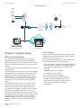
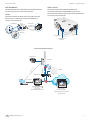
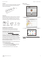
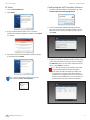
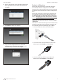
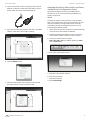
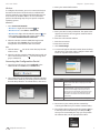
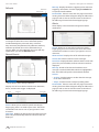
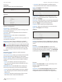
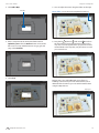
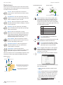
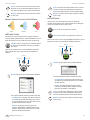
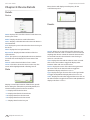
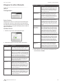
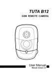
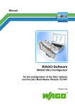
M2M Management System
Release Version: 1.1
mFi™ User Guide
Table of Contents
Table of Contents
Chapter 1: System Setup. . . . . . . . . . . . . . . . . . . . . . . . . . . . . . . . . . . . . . . . . . . . 1
mFi System Overview. . . . . . . . . . . . . . . . . . . . . . . . . . . . . . . . . . . . . . . . . . . . . . . . . . . . . . . . . . . . . 1
mFi Controller. . . . . . . . . . . . . . . . . . . . . . . . . . . . . . . . . . . . . . . . . . . . . . . . . . . . . . . . . . . . . . . . 1
mFi Hardware. . . . . . . . . . . . . . . . . . . . . . . . . . . . . . . . . . . . . . . . . . . . . . . . . . . . . . . . . . . . . . . . 2
Hardware Installation. . . . . . . . . . . . . . . . . . . . . . . . . . . . . . . . . . . . . . . . . . . . . . . . . . . . . . . . . . . . . 3
Software Download and Installation . . . . . . . . . . . . . . . . . . . . . . . . . . . . . . . . . . . . . . . . . . . . . . 3
Mac Users. . . . . . . . . . . . . . . . . . . . . . . . . . . . . . . . . . . . . . . . . . . . . . . . . . . . . . . . . . . . . . . . . . . . 3
PC Users . . . . . . . . . . . . . . . . . . . . . . . . . . . . . . . . . . . . . . . . . . . . . . . . . . . . . . . . . . . . . . . . . . . . . 4
Configuring the mFi Controller Software. . . . . . . . . . . . . . . . . . . . . . . . . . . . . . . . . . . . . . 4
Methods of Adoption . . . . . . . . . . . . . . . . . . . . . . . . . . . . . . . . . . . . . . . . . . . . . . . . . . . . . . . . 5
Accessing the Configuration Portal . . . . . . . . . . . . . . . . . . . . . . . . . . . . . . . . . . . . . . . . . . . 7
Chapter 2: Using the mFi Software. . . . . . . . . . . . . . . . . . . . . . . . . . . . . . . . . . 8
Interface Tabs. . . . . . . . . . . . . . . . . . . . . . . . . . . . . . . . . . . . . . . . . . . . . . . . . . . . . . . . . . . . . . . . . . . . 8
Common Interface Options. . . . . . . . . . . . . . . . . . . . . . . . . . . . . . . . . . . . . . . . . . . . . . . . . . . . . . . 8
mPower Status. . . . . . . . . . . . . . . . . . . . . . . . . . . . . . . . . . . . . . . . . . . . . . . . . . . . . . . . . . . . . . . 8
mPort Status. . . . . . . . . . . . . . . . . . . . . . . . . . . . . . . . . . . . . . . . . . . . . . . . . . . . . . . . . . . . . . . . . 8
Refresh . . . . . . . . . . . . . . . . . . . . . . . . . . . . . . . . . . . . . . . . . . . . . . . . . . . . . . . . . . . . . . . . . . . . . . 9
Recent Events. . . . . . . . . . . . . . . . . . . . . . . . . . . . . . . . . . . . . . . . . . . . . . . . . . . . . . . . . . . . . . . . 9
Alerts. . . . . . . . . . . . . . . . . . . . . . . . . . . . . . . . . . . . . . . . . . . . . . . . . . . . . . . . . . . . . . . . . . . . . . . . 9
Settings. . . . . . . . . . . . . . . . . . . . . . . . . . . . . . . . . . . . . . . . . . . . . . . . . . . . . . . . . . . . . . . . . . . . . 10
Admin. . . . . . . . . . . . . . . . . . . . . . . . . . . . . . . . . . . . . . . . . . . . . . . . . . . . . . . . . . . . . . . . . . . . . . 10
Chapter 3: Map Tab. . . . . . . . . . . . . . . . . . . . . . . . . . . . . . . . . . . . . . . . . . . . . . . . 11
Adding a Map. . . . . . . . . . . . . . . . . . . . . . . . . . . . . . . . . . . . . . . . . . . . . . . . . . . . . . . . . . . . . . . . . . . 11
Device Icons. . . . . . . . . . . . . . . . . . . . . . . . . . . . . . . . . . . . . . . . . . . . . . . . . . . . . . . . . . . . . . . . . . . . . 13
Motion Sensor Detection Field States. . . . . . . . . . . . . . . . . . . . . . . . . . . . . . . . . . . . . . . . 14
mPower Icons. . . . . . . . . . . . . . . . . . . . . . . . . . . . . . . . . . . . . . . . . . . . . . . . . . . . . . . . . . . . . . . . . . . 14
mPort Icons. . . . . . . . . . . . . . . . . . . . . . . . . . . . . . . . . . . . . . . . . . . . . . . . . . . . . . . . . . . . . . . . . . . . . 14
Map Display Options . . . . . . . . . . . . . . . . . . . . . . . . . . . . . . . . . . . . . . . . . . . . . . . . . . . . . . . . . . . . 15
Setting the Map Scale. . . . . . . . . . . . . . . . . . . . . . . . . . . . . . . . . . . . . . . . . . . . . . . . . . . . . . . 15
Chapter 4: Data Tab . . . . . . . . . . . . . . . . . . . . . . . . . . . . . . . . . . . . . . . . . . . . . . . 16
Date Range. . . . . . . . . . . . . . . . . . . . . . . . . . . . . . . . . . . . . . . . . . . . . . . . . . . . . . . . . . . . . . . . . . . . . .16
Views . . . . . . . . . . . . . . . . . . . . . . . . . . . . . . . . . . . . . . . . . . . . . . . . . . . . . . . . . . . . . . . . . . . . . . . . . . . 17
Renaming or Deleting a View. . . . . . . . . . . . . . . . . . . . . . . . . . . . . . . . . . . . . . . . . . . . . . . . 17
Data Panel Mouseover Functionality. . . . . . . . . . . . . . . . . . . . . . . . . . . . . . . . . . . . . . . . . 17
Devices . . . . . . . . . . . . . . . . . . . . . . . . . . . . . . . . . . . . . . . . . . . . . . . . . . . . . . . . . . . . . . . . . . . . . . . . . 18
Ubiquiti Networks, Inc.
i
mFi™ User Guide
Table of Contents
Chapter 5: Events Tab. . . . . . . . . . . . . . . . . . . . . . . . . . . . . . . . . . . . . . . . . . . . . . 19
Filter. . . . . . . . . . . . . . . . . . . . . . . . . . . . . . . . . . . . . . . . . . . . . . . . . . . . . . . . . . . . . . . . . . . . . . . . . . . . 19
Date Range. . . . . . . . . . . . . . . . . . . . . . . . . . . . . . . . . . . . . . . . . . . . . . . . . . . . . . . . . . . . . . . . . . . . . .19
Devices . . . . . . . . . . . . . . . . . . . . . . . . . . . . . . . . . . . . . . . . . . . . . . . . . . . . . . . . . . . . . . . . . . . . . . . . . 20
Events. . . . . . . . . . . . . . . . . . . . . . . . . . . . . . . . . . . . . . . . . . . . . . . . . . . . . . . . . . . . . . . . . . . . . . . . . . . 20
Temporal Distribution. . . . . . . . . . . . . . . . . . . . . . . . . . . . . . . . . . . . . . . . . . . . . . . . . . . . . . . 20
Device Distribution. . . . . . . . . . . . . . . . . . . . . . . . . . . . . . . . . . . . . . . . . . . . . . . . . . . . . . . . . . 20
Chapter 6: Rules Tab. . . . . . . . . . . . . . . . . . . . . . . . . . . . . . . . . . . . . . . . . . . . . . . 21
Rules. . . . . . . . . . . . . . . . . . . . . . . . . . . . . . . . . . . . . . . . . . . . . . . . . . . . . . . . . . . . . . . . . . . . . . . . . . . . 21
Creating Rules. . . . . . . . . . . . . . . . . . . . . . . . . . . . . . . . . . . . . . . . . . . . . . . . . . . . . . . . . . . . . . . . . . . 22
Rule Management. . . . . . . . . . . . . . . . . . . . . . . . . . . . . . . . . . . . . . . . . . . . . . . . . . . . . . . . . . . . . . . 24
Chapter 7: Devices Tab . . . . . . . . . . . . . . . . . . . . . . . . . . . . . . . . . . . . . . . . . . . . 25
Devices . . . . . . . . . . . . . . . . . . . . . . . . . . . . . . . . . . . . . . . . . . . . . . . . . . . . . . . . . . . . . . . . . . . . . . . . . 25
mFi Management . . . . . . . . . . . . . . . . . . . . . . . . . . . . . . . . . . . . . . . . . . . . . . . . . . . . . . . . . . . . . . . 26
Chapter 8: Device Details. . . . . . . . . . . . . . . . . . . . . . . . . . . . . . . . . . . . . . . . . . 27
Details . . . . . . . . . . . . . . . . . . . . . . . . . . . . . . . . . . . . . . . . . . . . . . . . . . . . . . . . . . . . . . . . . . . . . . . . . . 27
Device. . . . . . . . . . . . . . . . . . . . . . . . . . . . . . . . . . . . . . . . . . . . . . . . . . . . . . . . . . . . . . . . . . . . . . 27
Data . . . . . . . . . . . . . . . . . . . . . . . . . . . . . . . . . . . . . . . . . . . . . . . . . . . . . . . . . . . . . . . . . . . . . . . . . . . . 27
Events. . . . . . . . . . . . . . . . . . . . . . . . . . . . . . . . . . . . . . . . . . . . . . . . . . . . . . . . . . . . . . . . . . . . . . . . . . . 27
Serial-Based Device Details. . . . . . . . . . . . . . . . . . . . . . . . . . . . . . . . . . . . . . . . . . . . . . . . . . . . . . 28
Device. . . . . . . . . . . . . . . . . . . . . . . . . . . . . . . . . . . . . . . . . . . . . . . . . . . . . . . . . . . . . . . . . . . . . . 28
Serial Configuration. . . . . . . . . . . . . . . . . . . . . . . . . . . . . . . . . . . . . . . . . . . . . . . . . . . . . . . . . 28
Chapter 9: mPort Details. . . . . . . . . . . . . . . . . . . . . . . . . . . . . . . . . . . . . . . . . . . 29
mPort. . . . . . . . . . . . . . . . . . . . . . . . . . . . . . . . . . . . . . . . . . . . . . . . . . . . . . . . . . . . . . . . . . . . . . . . . . . 29
Configuration. . . . . . . . . . . . . . . . . . . . . . . . . . . . . . . . . . . . . . . . . . . . . . . . . . . . . . . . . . . . . . . 29
Details. . . . . . . . . . . . . . . . . . . . . . . . . . . . . . . . . . . . . . . . . . . . . . . . . . . . . . . . . . . . . . . . . . . . . . 30
mPort Serial . . . . . . . . . . . . . . . . . . . . . . . . . . . . . . . . . . . . . . . . . . . . . . . . . . . . . . . . . . . . . . . . . . . . 30
Configuration. . . . . . . . . . . . . . . . . . . . . . . . . . . . . . . . . . . . . . . . . . . . . . . . . . . . . . . . . . . . . . . 30
Details. . . . . . . . . . . . . . . . . . . . . . . . . . . . . . . . . . . . . . . . . . . . . . . . . . . . . . . . . . . . . . . . . . . . . . 30
Chapter 10: mPower Details. . . . . . . . . . . . . . . . . . . . . . . . . . . . . . . . . . . . . . . 31
Configuration. . . . . . . . . . . . . . . . . . . . . . . . . . . . . . . . . . . . . . . . . . . . . . . . . . . . . . . . . . . . . . . . . . . 31
Associating a Device with an Outlet. . . . . . . . . . . . . . . . . . . . . . . . . . . . . . . . . . . . . . . . . . 31
Reassigning a Device to Another Outlet . . . . . . . . . . . . . . . . . . . . . . . . . . . . . . . . . . . . . 31
Outlet Device Details. . . . . . . . . . . . . . . . . . . . . . . . . . . . . . . . . . . . . . . . . . . . . . . . . . . . . . . . 31
Outlet Device Data. . . . . . . . . . . . . . . . . . . . . . . . . . . . . . . . . . . . . . . . . . . . . . . . . . . . . . . . . . 32
Details . . . . . . . . . . . . . . . . . . . . . . . . . . . . . . . . . . . . . . . . . . . . . . . . . . . . . . . . . . . . . . . . . . . . . . . . . . 32
Overview . . . . . . . . . . . . . . . . . . . . . . . . . . . . . . . . . . . . . . . . . . . . . . . . . . . . . . . . . . . . . . . . . . . 32
Ubiquiti Networks, Inc.
ii
mFi™ User Guide
Table of Contents
Appendix A: Pinouts . . . . . . . . . . . . . . . . . . . . . . . . . . . . . . . . . . . . . . . . . . . . . . 33
mPort-S Serial DB9 . . . . . . . . . . . . . . . . . . . . . . . . . . . . . . . . . . . . . . . . . . . . . . . . . . . . . . . . . . . . . . 33
mPort-S Terminal Block. . . . . . . . . . . . . . . . . . . . . . . . . . . . . . . . . . . . . . . . . . . . . . . . . . . . . . . . . . 33
RS232. . . . . . . . . . . . . . . . . . . . . . . . . . . . . . . . . . . . . . . . . . . . . . . . . . . . . . . . . . . . . . . . . . . . . . . 33
RS422/RS485. . . . . . . . . . . . . . . . . . . . . . . . . . . . . . . . . . . . . . . . . . . . . . . . . . . . . . . . . . . . . . . . 33
Appendix B: Contact Information. . . . . . . . . . . . . . . . . . . . . . . . . . . . . . . . . . 34
Ubiquiti Networks Support. . . . . . . . . . . . . . . . . . . . . . . . . . . . . . . . . . . . . . . . . . . . . . . . . . . . . . 34
Online Resources. . . . . . . . . . . . . . . . . . . . . . . . . . . . . . . . . . . . . . . . . . . . . . . . . . . . . . . . . . . . 34
Ubiquiti Networks, Inc.
iii
mFi™ User Guide
Chapter 1: System Setup
mFi Example Diagram
mFi-MSW
mPort
Fan
Light
mFi-THS
SPEED
CONSOLE
0
1
2
EdgeRouter Lite
mPower
UniFi AP
or
mFi Controller
(On-Site Management Station)
mFi Controller
(Off-Site Cloud/NOC)
Chapter 1: System Setup
mFi System Overview
mFi™ is a M2M management software solution from
Ubiquiti Networks, Inc. that is designed to work with
Ubiquiti’s mFi product line. The software interface design
is based on the popular and easy to use UniFi™ software
interface.
The mFi Example Diagram above illustrates an example of
an mFi network.
The mFi Controller is connected to a router (in the example
the EdgeRouter Lite is used but not required). The router
is connected via Ethernet to the mPort (the mPort can
alternatively be connected wirelessly to a Wi‑Fi Access
Point ). The mPort has a motion sensor (mFi‑MSW) and
temperature sensor (mFi-THS) connected using RJ45
cabling.
The router is connected to a Wi-Fi access point, which
in this example is the UniFi AP (recommended, but not
required). The UniFi AP is connected wirelessly to the
mPower power strip which is controlling a fan and a light.
mFi Controller
The mFi Controller software allows you to monitor and
manage your mPort, mPower, mSensor, and third party
devices from your web browser.
The mFi Controller software can run on a computer that
meets the following minimum requirements:
• Microsoft Windows 7, Windows Vista, Windows XP, Mac
OS X, or Ubuntu Linux version 11.04. 64-Bit Operating
System Recommended (32-Bit only supports 2 GB
Database)
• 2 GB RAM is highly recommended
• Java Runtime Environment 1.6
(1.6.0_26 or above recommended)
The mFi Controller requires a web browser for
configuration with the following requirements:
• Web browser: Mozilla Firefox, Google Chrome, or
Microsoft Internet Explorer 8 (or above)
• FlashPlayer 10
The mFi Controller software allows you to create rules
that trigger actions based on data from your mFi sensors.
Using the example network above, a rule could be created
to turn the light on when motion is detected by the
mFi-MSW. Another rule could power on the fan when a
temperature is detected above a specified level by the
mFi-THS.
Ubiquiti Networks, Inc.
1
mFi™ User Guide
Chapter 1: System Setup
mFi Hardware
mPort Serial The Ubiquiti Networks mFi platform has multiple solutions
for connecting devices to the mFi Controller.
The mPort Serial features RS232/422/485 serial
connectivity through a standard DB9 serial port or a
terminal block connector. It has built-in Wi-Fi and Ethernet
to connect to the IP network.
mPort
The mPort has two mFi RJ45 connectors and a terminal
block connector. It has built-in Wi-Fi and Ethernet to
connect to the IP network.
mFi RJ45 Ports
Ethernet Port
to connect to
PoE and LAN
mFi Terminal
Block Port
Serial DB9 Port
Ethernet Port
Serial Terminal
Block Port
mPort Serial Example Diagram
Router Console
mPort Serial
UniFi AP
SPEED
CONSOLE
0
1
2
2:
EdgeRouter Lite
Telnet 2323
1:
Te
l
ne
t
23
23
or
2: WebShell
mFi Controller
(On-Site Management Station)
or
*
mFi Controller
(Off-Site Cloud/NOC)
* Need port 2323 open if the cloud is
outside a firewall
Ubiquiti Networks, Inc.
2
mFi™ User Guide
Chapter 1: System Setup
mPower Mac Users
mPower is a mFi Power Strip with independent, switchable
AC ports, and energy monitoring. It has built-in Wi-Fi to
connect to the IP network.
1. Click the Install icon.
mSensors
Ubiquiti Networks offers a variety of sensors to connect to
the mPort and your mFi network. These sensors connect
to the mPort using a standard RJ45 cable, except for the
mFi-DS, which connects using a terminal block connector.
Ceiling Mount
Motion Sensor
Wall Mount
Motion Sensor
Temperature
Sensor
mFI-MSC
mFi-MSW
mFi-THS
2. Click Continue and follow the on-screen instructions to
install the software.
Current Sensor Door Sensor
mFi-CS
mFi-DS
Hardware Installation
Follow the directions in the Quick Start Guide that
accompanied your Ubiquiti Networks mFi product.
3. Go to Go > Applications and double-click the mFi icon.
For third party products, refer to any documentation you
may have for the product. You may also want to check our
mFi user forum at forum.ubnt.com.
For pinout information, refer to “Pinouts” on page 33.
Software Download and Installation
The mFi Controller software is installed just once when
you initially create a mFi network. Devices can be added at
any time through the controller interface but you do not
need to go through the software installation process every
time you add another mFi device.
Proceed to “Configuring the mFi Controller Software”
on page 4.
The mFi Controller software can be downloaded from the
Ubiquiti Networks website.
1. Go to downloads.ubnt.com/mfi
2. Mac users should download mFi.dmg and Windows
users should download mFi-installer.exe.
3. Follow the instructions for your computer type.
Ubiquiti Networks, Inc.
3
mFi™ User Guide
Chapter 1: System Setup
PC Users
Configuring the mFi Controller Software
1. Launch mFi-installer.exe.
1. The mFi Controller software startup will begin. Click
Launch a Browser to Manage Network.
2. Click Install.
3. If your computer doesn’t have Java 1.6 or above
installed, you will be prompted to install it. Click Install
to continue.
2. The mFi Configuration Wizard will appear the first
time you launch the mFi Controller software. On the
Welcome screen, select your language and country.
Click Next.
4. Ensure the Start mFi Controller after installation option
is checked and click Finish.
3. Any devices that have already been discovered at this
point. Select the device(s) that you want to configure.
The Refresh button can be used to refresh the list of
devices. Click Next to continue.
Note: The mFi Controller software can also be
launched from Start > All Programs.
Ubiquiti Networks, Inc.
Note: Devices that you have already connected
to your DHCP enabled network will appear
here, unless already managed by another mFi
Controller. Once the mFi Controller software is
installed, you can add devices to mFi at any time.
Devices can be added later. It is not necessary to
install all devices during software installation.
4
mFi™ User Guide
4. Enter an administrator name in the Admin Name field.
Enter a password in the Password and Confirm fields.
Click Next.
Chapter 1: System Setup
Methods of Adoption
Devices that were not found or connected during the
mFi Controller software configuration can be added
afterwards. The mPort and mPort Serial can be connected
via Ethernet or Wi-Fi. The mPower must be configured via
Wi-Fi.
Devices that are not on the same Layer 2 network as the
mFi Controller and devices being added via Wi-Fi must
be added through the Configuration Portal of the device.
Refer to “Adopting the mPort, mPort Serial, or mPower
via the Device’s Configuration Portal” on page 6.
Adopting the mPort or mPort Serial via Layer
2 Ethernet
5. Click Finish to confirm your settings.
If the mPort or mPort Serial that you want to add to an mFi
network is connected to the same layer 2 network as the
mFi Controller, perform the following steps to add it:
1. Connect an Ethernet cable to the Ethernet port.
6. A login screen will appear for the mFi Controller
management interface. Enter the Admin Name and
Password that you created and click Login.
2. Connect the other end of the Ethernet cable to the
Ethernet port labeled POE on the PoE Adapter.
3. Connect an Ethernet cable from your LAN to the
Ethernet port labeled LAN on the PoE Adapter.
Ubiquiti Networks, Inc.
5
mFi™ User Guide
4. Connect the power cord to the power port on the PoE
Adapter. Connect the other end of the power cord to a
power outlet. The Power LED should light up.
Chapter 1: System Setup
Adopting the mPort, mPort Serial, or mPower
via the Device’s Configuration Portal
The Device Configuration Portal is embedded in the
hardware. It can be accessed with a wired Ethernet or
wireless connection.
Wired
To adopt the mPort or mPort Serial by a mFi Controller
that is not located on the same layer 2 network, you must
enter the IP address and login information of the mFi
Controller in the Device Configuration Portal. To do so,
performing the following steps:
5. Go to the mFi Controller interface and click on the MAC
address of the device listed under pending.
1. Make sure that your host machine is connected directly
to the mPort or mPort Serial via Ethernet.
2. Configure the Ethernet adapter on your host system
with a static IP address on the 192.168.1.x subnet.
3. Launch your web browser and type
http://192.168.1.20 in the address field. Press enter
(PC) or return (Mac).
4. Enter your network information:
6. Click the Adopt button.
a. Enter the mFi Controller address.
b. Enter the User Name.
c. Enter the Password.
7. The device will appear in the left panel. Click the x in
the upper right to close the Details window.
Ubiquiti Networks, Inc.
d. Click Save Settings.
6
mFi™ User Guide
Chapter 1: System Setup
Wireless
3. Enter your network information:
To configure the mPower, you must connect wirelessly to
the SSID of the device. The devices have a default SSID
(wireless network name) labeled mFi followed by the last
six characters of the MAC address. To access the SSID,
perform the following steps for your specific computer
operating system:
Windows
1. Go to Connect to Network.
-- Windows 7 Right-click the Network
icon.
-- Windows Vista Go to Start > Connect To.
-- Windows XP Right-click the Wireless Network icon
in the System Tray (lower right corner of the screen).
Click View Available Wireless Networks.
2. Select the wireless network (SSID) that begins with
mFi and then click Connect. Go to Accessing the
Configuration Portal after the Mac instructions.
a. Enter your Wi-Fi security credentials. The options that
appear are based on the encryption method used on
your Wi-Fi network.
b. Enter the mFi Controller address.
c. Enter the User Name.
d. Enter the Password.
e. Click Save Settings.
Mac
1. Click the AirPort
of the screen).
icon in the menu bar (top left side
2. Select the wireless network (SSID) that begins with mFi.
Once connected, the AirPort
icon will change from
gray to solid black.
4. A screen will appear with information about checking
the device for connection status. Verify the Status LED
is blue. It may take a few moments.
Accessing the Configuration Portal
1. Launch your web browser. Type config.mfi in the
address field. Press enter (PC) or return (Mac).
2. The Configuration Portal will appear. Select the wireless
network name (SSID) of your existing wireless network
from the drop-down list. To refresh the list, click rescan.
LED Activity
Description
Flashing Yellow
Connecting to WiFi. After a minute or so, if it fails to
connect it will revert back to captive portal mode
(solid yellow)
Flashing Blue
Attempting to connect to server (once successfully
connected to WiFi, it will stay in this state until
it connects successfully to the server). If after 5
minutes it has not connected, such as if the server
information was wrong, the reset button can be
pressed for 5 seconds to revert back to Captive
Portal mode.
Solid Yellow
Captive Portal mode. mPower needs configured.
5. Reconnect to your existing wireless network by
selecting the SSID from your wireless network utility.
6. The mPower device appears with the mPower icon
in the left panel under the Drag on to Map heading.
Once you’ve customized your map, you can position
the mPower device in the appropriate location.
Ubiquiti Networks, Inc.
7
mFi™ User Guide
Chapter 2: Using the mFi Software
Chapter 2: Using the mFi
Software
The mFi software has a browser-based interface for easy
configuration and management.
Common Interface Options
The common interface options are accessible from all tabs
in the mFi interface.
mPower Status mPort Status
To access the interface, perform the following steps:
1. Launch the mFi application if hasn’t already been
started. Windows users go to Start > All Programs >
Ubiquiti mFi > mFi.
2. A window will open as the application is starting.
Once it is ready to launch, you will be able to click the
Launch a Browser to access mFi button.
mPower Status
3. The login screen will appear. Enter the admin name and
password in the appropriate fields and click Login.
mPower is a power strip with energy monitoring and
management capabilities when used with the mFi
Controller software. Power can be enabled or disabled for
each power outlet on the strip and energy costs can be
monitored. Clicking on a mPower in any of the lists will
display the mPower’s Configuration tab.
• active Drop-down clickable list of all of active mPower
units.
• inactive Drop-down clickable list of all mPower units
that were once active but are not currently active.
Interface Tabs
The mFi software consists of five primary tabs.
Interface tabs
• pending Drop-down clickable list of pending mPower
units. Pending devices have been discovered but
have not yet been assigned to be managed by an mFi
Controller. Select a device from this list, then click the
Adopt button from the device’s Details tab to manage it
from this Controller.
mPort Status
mPorts are points of connection for your sensors,
machines, and/or devices. The mPort supports mFi RJ45
and terminal block connections. The mPort Serial supports
serial-based connections. Clicking on a mPort in any of the
lists will display the mPort’s Configuration tab.
• active Drop-down clickable list of all of the mPorts that
are online.
• inactive Drop-down clickable list of all of the mPorts
that were once active but are not currently active.
This User Guide covers each tab with a chapter. For details
on a specific tab, refer to the appropriate chapter.
• “Map Tab” on page 11
• “Data Tab” on page 16
• “Events Tab” on page 19
• pending Drop-down clickable list of pending mPorts.
Pending devices have been discovered but have not
yet been assigned to be managed by an mFi Controller.
Select a device from this list, then click the Adopt
button from the device’s Details tab to manage it from
this Controller.
• “Rules Tab” on page 21
• “Devices Tab” on page 25
Ubiquiti Networks, Inc.
8
mFi™ User Guide
Chapter 2: Using the mFi Software
Refresh
Refresh Rate
Refresh button
Message Displays the device, triggering value, and event
triggering information. Click the highlighted Details link
to open the Details window.
Events Slider If there is more than one page of events for
viewing, the Events slider will appear. Drag the slider to the
page you wish to view or click the arrows on the side of
the slider to go forward or backward page by page.
Alerts
Alerts displays a list of network management related
notifications.
Choose an option from the Refresh Rate pull-down menu
to change how often the screen is refreshed. Options
include Manually, Every 5 Seconds, Every 15 Seconds,
Every 30 Seconds, Every Minute, Every 2 Minutes, and Every
5 Minutes. By default, the screen is refreshed every 2
minutes. When you select Manually, the screen will only
update when you click the Refresh button.
Recent Events
Search Allows you to search for specific text. Simply
begin typing, there is no need to press enter. The results
are filtered in real-time as soon as you type two or more
characters.
Show Archived Displays a list of all archived messages.
Archive All Archives all of the current messages.
Date/Time Displays the date and time that the event took
place. The year/month/day and hour:minute:seconds are
displayed.
Message Details of the alert are listed here. Some
messages contain clickable links which are highlighted in
blue. These links will open the device details window.
Actions • Archive Click this button to archive the alert message
to the left of the button.
• Adopt Click this button to adopt a pending mPort.
Recent Events, Alerts, Settings and Admin
Displays a list of recent device related events. Date/time,
device, and the event trigger are displayed.
Search
Details link
Events slider
Events Slider If there is more than one page of events for
viewing, the Events slider will appear. Drag the slider to the
page you wish to view or click the arrows on the side of
the slider to go forward or backward page by page.
Search Allows you to search for specific text. Simply
begin typing, there is no need to press enter. The results
are filtered in real-time as soon as you type two or more
characters.
Date/Time Displays the date and time that the event took
place. The year/month/day and hour:minute:seconds are
displayed.
Ubiquiti Networks, Inc.
9
mFi™ User Guide
Settings
Settings contains System and Admin Settings.
Chapter 2: Using the mFi Software
• Password Enter the password associated with the
username that will be used to send email notifications.
Apply Click Apply to save changes.
Admin Settings
System
Admin Name Displays the current admin name used
to login. To change the admin name, simply enter a new
name and click Apply.
Password A new password can be entered in this field. Be
sure to enter the password again in the Confirm field and
then click Apply to save your new password.
Confirm Used to confirm your new password.
System Configuration
Language Selects the language for use in the interface.
System Name mFi System name.
Apply Click Apply to save changes.
Country Select the country the product is being used in
from the drop-down list.
Admin
Time Zone Select the appropriate time zone from the
drop-down list.
Temperature Unit Select Celsius or Fahrenheit for
temperature data.
Currency Symbol (eg $) Enter the currency symbol to be
used with the energy price. Energy Price Enter a price per kWh to be used with
mPower devices to calculate an estimate of power costs.
Note: The energy price is just a rough estimate. Many
utilities have time-of-use billing, meaning the price
varies through the day and/or prices that vary based
on the overall amount of energy used in a month.
Use an average number from a previous utility bill .
Services
Server Information
Version The software version is displayed here. If there is
an update, mFi will automatically download it and display
it here.
Backup
Download Click Backup Database to download a
backup of the data. You will have the option to select the
time period of the data that you backup. Click Download
to backup the mFi database for the selected time period.
Automatic Upgrade Option to enable automatic
firmware upgrades.
Network Discovery Allows you to Make mFi discoverable
via UPnP (Universal Plug and Play) over the network.
Remote Logging Option to Enable Remote Syslog. When
enabled, you need to enter the server address and port
number.
• Server The address of the Remote Syslog Server.
• Port The port used for the Remote Syslog Server. The
default port is 514.
Mail/SMTP Server The Mail/SMTP Server settings are
necessary to allow mFI to send out email notifications.
• Server Enter the SMTP (outgoing) mail server address.
• Port Enter the port used for communication with the
SMTP server.
Restore
Browse Click Choose File to locate a previously saved
backup configuration file to restore.
Support Info
Download Click Download Support Info to download
a file to your computer with information about your
configuration that can be emailed to our support team.
• Username Enter the email username of the account
that will be used to send email notifications.
Ubiquiti Networks, Inc.
10
mFi™ User Guide
Chapter 3: Map Tab
Chapter 3: Map Tab
Adding a Map
The mFi Controller software allows you to upload custom
map images of your location for a visual representation of
your mFi device layout. When you initially launch mFi, a
default sample map is displayed.
To add a custom map, you must first create the image.
You can add an image you’ve created or photo that
you’ve taken as a map image background. You can use
an illustration, image editing, or blueprint application to
create a map or take a photo of your location. Map files
can be in .jpg, .gif, or .png file formats.
Once you’ve created the map, you can upload it to the mFi
software by performing the following steps:
1. Click Configure Maps.
Configure Maps button
You can have multiple maps with device locations placed
and stored separately for each map. This allows you to
manage/monitor everything connected in your mFi
network whether it is in a different room, floor, or building.
Ubiquiti Networks, Inc.
11
mFi™ User Guide
Chapter 3: Map Tab
2. Click Add a Map.
5. You can adjust the zoom using the slider on the right.
Add a Map
3. Enter a map name in the Description field and click
Upload my own. Click the Browse button to locate the
file to use as a map (valid file formats are .jpg, .gif, and
.png). Click Continue.
4. Click Close.
Zoom Slider Use to zoom the map detail in and out.
6. Drag Device , mPower , and mPort
icons from
the list on the left to the appropriate location on the
map. The icons will appear where you place them and
remain linked to the map that you place them on until
you remove them.
Repeat steps 1-6 to add additional rooms, floors, or
buildings connected to your mFi network. After you’ve
added all of the locations, you can switch between them
using the Map Selector.
Map Selector
Ubiquiti Networks, Inc.
12
mFi™ User Guide
Chapter 3: Map Tab
Device Icons
Serial Based Device
Sensor Outlet
Device icons are placed on the map to show the location
of your devices. Click and hold the icon to drag the Device
to another location on the map.
Current This icon represents an electrical
current sensor. Current sensors measure values
in amps.
Power icon
Turns on/off power. Green when powered.
Shell icon
Door/Window This icon represents a door or
window sensor. These sensors indicate whether
a door or window is open or closed.
Generic This icon represents a generic device
that doesn’t fall into another category. It returns
an on or off value.
Humidity This icon represents a humidity
sensor. Humidity sensors provide a percentage
value measurement.
Motion This icon represents a motion
detection sensor. A visual representation of the
motion detection field is displayed and can be
edited on the map. When motion is detected,
this field changes colors on the map.
Sensor Outlet This icon represents a power
outlet on an mPower device. It returns an on or
off value and displays watts used.
Serial-Based Device This icon represents a
serial-based device such as a switch that is
connected via a serial port.
Temperature This icon represents a
temperature sensor. Temperature values can be
displayed in degrees Celsius or Fahrenheit.
Click on the Device icon to reveal additional options. Click
a blank area of the map to hide the additional options.
Chart Displays a chart of color coded values
representing low, average, and high values or
event frequency based on the type of device.
The time frame of the chart can be changed by
clicking the letters in the upper right corner. See
the chart below for values:
H
Displays data for the last hour.
D
Displays data for the last 24 hours.
W
Displays data for the last week.
M
Displays data for the last month.
Y
Displays data for the last year.
Chart Time Frame Selections
Note: This option is not available for
serial-based devices.
Shell Opens up a command line interface shell
(only available for serial-based devices).
Note: If your mFi Controller is outside
of a firewall, be sure that TCP port 2323
(inbound) is open on your firewall.
Power Toggles power off or on. Icon is green
when powered on. (available only on Sensor
Outlet icons and Generic device icons with
output 5v, 12v, or 24v).
Details Brings up the Device Details window.
Motion Sensor
Lock icon
Details icon
Remove icon
Adjustable Motion Detection Field allows
you to define the visual representation of
the motion sensor detection field.
Note: This doesn’t adjust the field of
motion detection on the sensor.
Chart icon
The Device Details window includes the Details,
Data, and Events tabs.
• Details Displays the Name, Model, mPort,
and Port.
• Data Displays data from the last H|D|W|M|Y.
• Events Displays a searchable list of events.
Event details such as the time, date, sensor,
sensor type, the value, and the rule that
triggered the event are displayed here.
Refer to “Device Details” on page 27 for
additional information.
Ubiquiti Networks, Inc.
13
mFi™ User Guide
Chapter 3: Map Tab
Lock Locks the selected sensor to the current
location on the map and disables the Remove
icon functionality for this sensor while locked.
Lock Locks the selected mPower to the current
location on the map and disables the Remove
icon functionality for this mPower while locked.
Remove Remove the sensor from the location
on the map.
Remove Remove the mPower from the location
on the map.
Motion Sensor Detection Field States
mPort Icons
mPort icons can be placed on the map to show the
location of the mPort. Click and hold the icon to drag the
mPort to another location on the map.
mPort This icon represents a mPort.
Motion
No Motion
Alert
mPower Icons
mPower icons can be placed on the map to show the
location of the mPower device. Click and hold the icon to
drag the mPower icon to another location on the map.
mPower This icon represents a mPower device.
It can be a mPower Mini, mPower, or mPower
Pro outlet.
mPort-Serial This icon represents a mPort-S.
Click on the mPort icon to reveal additional options. Click a
blank area of the map to hide the additional options.
Lock icon
Details icon
Remove icon
Click on the mPower icon to reveal additional options.
Click a blank area of the map to hide the additional
options.
Lock icon
Details icon
Remove icon
Details Brings up the mPort Details window.
Details Brings up the mPower Details window.
The mPort Details window contains two tabs.
• Configuration Displays the devices that are
currently connected and allows you to add or
change devices.
• Details Displays the Name, Last Contact,
Last Alert, Last Event, MAC Address, Model,
Firmware, IP Address, and Uptime.
The mPower Details window contains two tabs.
• Configuration Displays the devices that are
currently connected and allows you to add
or change devices. You can also click to view
details and detach the device.
Lock Locks the selected mPort to the current
location on the map and disables the Remove
icon functionality for this mPort while locked.
Remove Remove the mPort from the location
on the map.
• Details Displays the Name, Type, Last
Contact, MAC Address, Model, Firmware, IP
Address, and Uptime. There are also Locate,
Restart, and Remove buttons.
Ubiquiti Networks, Inc.
14
mFi™ User Guide
Chapter 3: Map Tab
Map Display Options
Show: Select to show values, labels, details and topology.
The following are the options available:
• Values Displays real-time values of Device data. Buttons
display the current state of the device.
2. Click and hold to draw a line in the area that you want
to use to set the scale of the map. If you need to redraw
the line, just click and hold again to draw a new line.
Once you’re happy with the line, click Next.
• Labels Displays the name of the Device or mPort.
• Details Displays details for the Device or mPort.
• Topology Displays which sensors are connected to
which mPorts.
Map: If multiple maps have been uploaded, you can
select which map you want to view using this option.
Configure Maps Use this option to add maps, edit the
name of an existing map, or remove a map from the list.
Zoom Slider Use to zoom the map detail in and out.
3. Enter the distance that the line represents in the
Distance: field. The distance is specified in meters by
default but you can switch to feet using the drop-down
selection menu on the right. Click Confirm.
Set Map Scale Use this option to define the scale of the
map. You will draw a line and define the distance that the
line represents.
Setting the Map Scale
1. Click the Set Map Scale
Ubiquiti Networks, Inc.
button.
15
mFi™ User Guide
Chapter 4: Data Tab
Chapter 4: Data Tab
Date Range
The Data tab allows you to view device data. You can set a
date range for data results, create customized views, and
compare data.
On the left side of the screen there are three selection
panels: Date Range, Views, and Devices. On the right side of
the screen, data is displayed based on the selections made
in the selection panels.
• From Click in the From date field and a calendar will
appear that will allow you to select a beginning date.
Click the time field and either manually enter a time or
use the arrows to select an hour.
• To Click in the To date field and a calendar will appear
that will allow you to select an ending date. Click the
time field and either manually enter a time or use the
arrows to select an hour.
Quick Links Quick links display the data values for the
selected time period:
Selection Panels
Data Panels
-- Last Hour Displays data for the last hour.
-- Day Displays data for the last day.
-- Week Displays data for the last week.
-- Month Displays data for the last month.
Ubiquiti Networks, Inc.
16
mFi™ User Guide
Chapter 4: Data Tab
Views
Data Panel Mouseover Functionality
Custom views can be created, saved, and selected for
viewing here.
Use the mouse to hover over the data timeline and view
specific details.
Create View Click to create a new view. Drag and drop
devices from the selection panel on the left side of the
screen to the data panel on the right side of the screen to
display data from multiple devices in one view. Sizing and
positioning are determined by where you drop the device
data in the view. You can drag and drop similar devices
into the same data grid to compare values.
Save As... Click to save a new view. You will be prompted
to enter a name for the new view. Enter the name and
click Save. Click Cancel if you don’t wish to save the view.
Discard Click if you do not wish to save the new view.
Click and highlight specific areas of the timeline to zoom
in on a specific section of the timeline. A magnifying
glass icon will appear and the timeframe you select will
be highlighted with a beige color. After making your
selection, all of the devices in the view will zoom to the
timeframe you specify. Use the Quick Links under the Data
Range selection if you need to zoom back out.
Selecting the zoom area
Renaming or Deleting a View
To rename or delete a view, click the view name to select
the view. The edit and delete icons will appear to the right
of the view name.
Config Click the Config icon and the Rename View
window will open. Change the name and click
Save. Click Cancel if you don’t wish to rename the
view.
Remove Click the Remove icon next to the view
name. There is no confirmation, so be sure you
want to delete the view.
Ubiquiti Networks, Inc.
Detailed data from the zoom selection
17
mFi™ User Guide
Device names can be clicked on in the data panel to open
the Device Details window.
Chapter 4: Data Tab
Devices
Displays a list of the available devices categorized by type.
Click on a specific device to view the data for the device in
the data panel. When creating custom views, devices are
dragged from this selection panel to the data panel.
For information on the Device Details window, go to
“Device Details” on page 27.
If you wish to remove a device from the view, click the
remove icon to the far right of the device name. If you
wish to save the modified view, click Save. If you wish to
save it as a new view, click Save As... If you want to revert
to the previous view setting, click Discard.
Different data sets can be selected for Outlets in the Data
Panel from the upper right corner. Select the type of data
to display from the drop-down menu.
• Power Displays a chart of the power being used by the
device (in Watts) during the selected time frame.
• Output Displays a chart showing the on and off state
during the selected time frame.
• Power Factor Displays a chart of efficiency during the
selected time frame. A value of 1 is very good.
• Total Energy Displays a chart of the accumulation of
energy during the selected time frame.
• Voltage Displays a chart of the voltage during the
selected time frame. Device is off when 0 volts.
• Current Displays a chart of the amps flowing through
the device during the selected time frame.
Ubiquiti Networks, Inc.
18
mFi™ User Guide
Chapter 5: Events Tab
Chapter 5: Events Tab
Date Range
The Events tab displays event information that can be
filtered by search strings, date ranges, or devices. It also
displays distribution information in visual charts.
Filter
Filter Allows you to filter data using specific search
criteria. Any text that is entered is used as real‑time search
criteria and anything that doesn’t match the entered
characters will be removed from the view. Click Clear or
delete the search string to return to a normal view.
• From Click in the From date field and a calendar will
appear that will allow you to select a beginning date.
Click the time field and either manually enter a time or
use the arrows to select an hour.
• To Click in the To date field and a calendar will appear
that will allow you to select an ending date. Click the
time field and either manually enter a time or use the
arrows to select an hour.
Quick Links Quick links display the data values for the
selected time period:
-- Last Hour Displays data for the last hour.
-- Day Displays data for the last day.
-- Week Displays data for the last week.
-- Month Displays data for the last month.
Ubiquiti Networks, Inc.
19
mFi™ User Guide
Chapter 5: Events Tab
Devices
Device Distribution
Allows you to control which devices are included in the
event data that is displayed. Select or deselect individual
devices or entire device categories.
Device Distribution displays a pie chart representation of
events generated by specific devices during a specific
timeframe.
If specific timeframes are selected on the Temporal
Distribution graph, the timeframe will also be applied to
the Device Distribution graph.
The Device Distribution graph also updates when event
data is filtered using the Filters, Date Range, and Devices
selections or if a Quick Link is selected.
Events
Show/Hide Distribution Toggles between showing or
hiding the distribution graphs.
Temporal Distribution
Placing the mouse over an event will display the current
location of the device on the map, a 24 hour snapshot of
values, when the event occurred, the alarmed value, and
the last reported value.
Temporal Distribution displays a bar graph representation
of events generated during a specific timeframe. By
default, 2 hour increments during a 24 hour period are
displayed.
Click on any bar to display the specific events generated
during the selected timeframe. The Device Distribution
graph will also update to reflect the device distribution
during this timeframe. Click on the area outside of the
graph to return to the overview.
Event data can be filtered by using the Filters, Date Range,
and Devices selections. Clicking on a Quick Link will change
the timeframe reference of the graphs to the Last Hour,
Day, Week, or Month.
Ubiquiti Networks, Inc.
Time Displays the date and time that an event occurred.
Click on the Time header to toggle the display order
between oldest and most recent events.
Device Displays the name of the device that generated
the event. Click on the Device header to toggle the
alphabetical display order from a-z to z-a.
Type Displays the type of event. Click on the Type header
to toggle the alphabetical display order from a-z to z-a.
Value Displays the value that triggered the event. Click on
the Value header to toggle the numerical and alphabetical
display order from 0-9 to 9-0 and a-z to z-a.
Rule Displays the name of the rule that triggered the
event. Click on the Rule Name header to toggle the
alphabetical display order from a-z to z-a.
20
mFi™ User Guide
Chapter 6: Rules Tab
Chapter 6: Rules Tab
Rules
The Rules tab is where you can define conditions that
trigger actions and what actions occur once conditions are
met.
Rules
Rule Editor
Click on a rule to display the conditions and actions in the
Rule Editor or click Add a Rule to define a new rule.
Add a Rule Click to create a rule.
Ubiquiti Networks, Inc.
21
mFi™ User Guide
Creating Rules
Rules trigger actions when a specified condition or
conditions occur. For example, a rule might be created to
turn on a light when a door is opened. The door opening
is the condition and the action that is triggered is the light
turning on. Note that if the light is manually turned off
while the door is open, the rule will not trigger again until
the door has been closed and re-opened.
Chapter 6: Rules Tab
• Schedule The Schedule can be used for two things:
-- Scheduling an Action If a schedule is the only
condition of a rule, then the action will take place at
the scheduled start time. If an output is turned on, it
will turn off when the schedule period ends.
Note: If a scheduled time is used as a condition
and an output timer with a shorter duration is
used on the action, then the output will shut off
after the time of the output timer has expired.
-- Setting Activity Times If a rule contains conditions
with a scheduled time (or multiple) and one or more
sensor conditions or condition sets, then the rule is
only active during the scheduled time(s). For example,
if you were to create a schedule called “Active”,
and create a rule with the Active schedule, motion
sensors, and All Conditions selected, then the rule is
only triggered if motion is detected during the hours
defined in the Active schedule.
1. Enter the name for the rule in the field with the text
Please enter new rule name.
2. Click Add Condition.
3. Select a Sensor, Schedule, or Condition Set.
• Sensor Select this if you want an action to occur when
a sensor detects or is in a specific state.
a. Click the + symbol next to Schedule.
b. Enter a name for the schedule.
c. Click to highlight times for each day on the schedule.
d. Click Save.
• Condition Set A condition set can contain sensor
states, scheduled times, or other condition sets.
The use of Conditions sets and the Any Condition/All
Conditions selector allows for arbitrarily complex logic
conditions to be created (similar to nested and/or logic).
a. Select a device from the drop-down list.
b. Once a device is selected, applicable states for the
device are made available. For example, a condition
for a temperature sensor could be defined when the
temperature is above or is below a certain temperature.
Select a state.
c. Click Add.
Ubiquiti Networks, Inc.
22
mFi™ User Guide
Chapter 6: Rules Tab
4. (Optional) To add additional conditions, click Add
Condition.
a. Choose a device from the drop-down list.
5. Select whether Any Condition or All Conditions must
be met to trigger the action.
c. Select whether you want the device On or Off.
-- Any Condition Action is triggered if any of the
defined conditions occur.
-- All Conditions All conditions listed in the rule must
occur before the action is triggered.
6. Click Add Action.
b. Click Add.
d. Click the gear icon if you want to define how long the
device should stay on. A field will appear allowing you
to enter a number. Select Seconds, Minutes, or Hours
from the drop-down.
• Notification Allows you send an email notification,
event, or system alert when rule conditions are met.
7. Choose an Action:
• Script A script is a block of text that is sent out to
the serial port of the corresponding mPort Serial. This
option allows you to run a script.
a. Choose a device from the drop-down list.
b. Choose a script from the drop-down list or click the
New Script button. If you select New Script, the New
Script window will appear. Enter a name for the script,
the script details, and click Save.
c. Click Add.
• Output Allows you to set the state of a device.
Note: In order for email notifications to
work properly, Mail/SMTP server settings
must be configured on the Settings > System
page. Refer to “Services” on page 10 for
additional details. a. Select Notification and click Add.
b. Select Send Email, Generate Event or both options:
• Send Email Click to send an email notification
when rule conditions are met. Enter emails in the
Add Email(s) field and separate additional emails
with a space. Enter the amount of time to wait
before an action triggers another email by entering
a time in minutes in the Hold additional email alerts
for this event for __ minute(s) field.
Note: To send text messages, enter the address
of the Mail-to-SMS Gateway.
For example, for AT&T wireless, you would enter
[email protected]. A list of
gateways can be found on Wikipedia at
en.wikipedia.org/wiki/List_of_SMS_gateways
• Generate Event Click to generate an event when
rule conditions are met. A system alert can also be
generated by clicking on the Create System Alert
button. Enter the amount of time to wait before an
action triggers another event by entering a time
in minutes in the Don’t create an event again for __
minute(s) field.
8. You can add additional actions by clicking the Add
Action button. Once you’ve finished creating your rule,
click Save.
Ubiquiti Networks, Inc.
23
mFi™ User Guide
Chapter 6: Rules Tab
Rule Management
Rules that have been saved can be viewed by highlighting
the rule in the Rules panel. You can modify the rule by
making changes and saving the rule again. There are also
links to Delete Rule and Make a copy of this rule.
Existing rules can be enabled or disabled by clicking on
the On/Off button to the right of the rule name.
Ubiquiti Networks, Inc.
24
mFi™ User Guide
Chapter 7: Devices Tab
The Devices tab displays a list and details of the connected
devices and mPorts.
Devices
Chapter 7: Devices Tab
Model Displays the model information.
Device (port) Displays the name or MAC address of the
mPort the device is associated with and the port it is
connected to is displayed in parenthesis.
Value Displays the last reported value from the device.
Reported At Displays the time of the last reported value.
Actions Use the Locate button to display the device on
the map. Click Remove to remove an unattached device
from the system. Click Turn on or Turn Off for available
devices to change the state of the device.
Add Device Click to add a device. If you have multiple
mPorts, you will select the appropriate mPort.
Search Allows you to search for specific characters. Any
text that is entered is used as real‑time search criteria and
anything that doesn’t contain the entered characters will
be removed from the view. Delete the search string to
return to a normal view.
Connected Device Displays the name of the device. Click
on the name of the device to display the Device Details
window. For additional information on the Device Details
window, refer to “Device Details” on page 27.
mPort Status Displays the status of the mPort the device
is associated with.
Ubiquiti Networks, Inc.
25
mFi™ User Guide
Chapter 7: Devices Tab
mFi Management
Search Allows you to search for specific characters. Any
text that is entered is used as real‑time search criteria and
anything that doesn’t contain the entered characters will
be removed from the view. Delete the search string to
return to a normal view.
Name/MAC Address Displays the name or MAC address
of the mPort. Click on the name or MAC address of the
mPort to display the mPort Details window. For additional
information on the mPort Details window, refer to “mPort
Details” on page 29.
Status Indicates if the mPort is active.
Model Displays the model of the mPort.
Devices Displays the number of devices configured with
the mPort.
Channel Displays the wireless channel being used by the
mPort.
Uptime Displays the total uptime of the mPort.
Last Seen Displays the amount of time it had been since
the mPort was last seen when the page was loaded. To
refresh the values, reload the web page or navigate to
another tab and then back again.
Actions Use the Locate button to display the mPort on
the map. Click Restart to restart a mPort from the list. Click
Upgrade to upgrade to new firmware.
Ubiquiti Networks, Inc.
26
mFi™ User Guide
Chapter 8: Device Details
Chapter 8: Device Details
Binary devices will display event frequency for the
selected time period.
Details
Device
Events
Name Displays the name of the device To edit the name,
click the pencil icon.
Model Displays the device model information.
mPort Displays a clickable link to the mPort the device is
associated with.
Port Displays the port number that the device is using on
the mPort.
Value Displays the last reported value.
Reported At Displays the date and time of the last
reported value.
Active This option is only displayed on devices that have
an on/off state. It will display the current state of the
device.
Detach Used to detach the device from a mPort.
Locate Click this to locate the device on the map. The
sensor will be highlighted with a flashing beacon.
Data
Search Allows you to search for specific characters. Any
text that is entered is used as real‑time search criteria and
anything that doesn’t contain the entered characters will
be removed from the view. Delete the search string to
return to a normal view.
Time Displays the date and time that an event occurred.
Click on the Time header to toggle the display order
between oldest and most recent events.
Device Displays the name of the device that generated
the event. Click on the Device header to toggle the
alphabetical display order from a-z to z-a.
Type Displays the type of event. Click on the Type header
to toggle the alphabetical display order from a-z to z-a.
Value Displays the value that triggered the event. Click on
the Value header to toggle the numerical and alphabetical
display order from a-z to z-a.
Displays a visual representation of data for the specific
device during the selected time period. By default, D is
selected showing data from the last 24 hours.
• H Displays data for the last hour.
• D Displays data from the last 24 hours.
• W Displays data from the last week.
• M Displays data from the last month.
• Y Displays data from the last year.
Ubiquiti Networks, Inc.
27
mFi™ User Guide
Chapter 8: Device Details
Rule Displays the name of the rule that triggered the
event. Click on the Rule Name header to toggle the
alphabetical display order from a-z to z-a.
Serial-Based Device Details
Web Shell Opens up a command line interface shell.
Device
Name Displays the name of the device. To edit the name,
click the pencil icon.
Model Displays the device model information.
mPort Displays a clickable link to the mPort the
serial‑based device is associated with.
IP Address Displays the IP address used to communicate
with the device.
Port Displays the port used for Telnetting to the device.
Protocol Displays the protocol that is used to
communicate with the device.
Connected Host Displays the IP address of the Telnet
client connected to the mPort Serial. If the device is
connected via WebShell, it will display the IP address of
the mFi Controller. The Disconnect button will disconnect
the client.
Serial Configuration
Mode Displays the mode, RS232 or RS485.
Port DB9 or Terminal Block. When RS485 mode is
selected, the option to enable 120Ω Term is available. 120
Ohm termination enables a built-in 120 Ohm termination
resistor between the TX and RX lines.
Termination Displays termination method.
Speed Speed can be between 300 and 115200
Parity None, odd, or even.
Antenna Displays internal or external antenna.
Configure Use this button to change Serial Configuration
settings.
Detach Used to detach the device from a mPort.
Locate Click this to locate the device on the map. The
sensor will be highlighted with a flashing beacon.
Ubiquiti Networks, Inc.
28
mFi™ User Guide
Chapter 9: mPort Details
Chapter 9: mPort Details
Device Type
Description
Output 24v
Switch an external 24V relay. Outputs 24V on
the Output (O) pin, when the port is on, and 0v
otherwise. This type of machine displays an on/
off button in the mFi Controller interface, and
can be selected as an output when creating a
rule from the Rules tab.
Ubiquiti mFi-CS
Current Sensor
The Current Sensor measures the root-meansquare (RMS) voltage being received on the
A+ and A- pins and converts it to a current
measurement (using a conversion factor of 1V =
100 amps). It is optimized for linear loads (nonlinear loads will have reduced accuracy).
Ubiquiti mFi-DS
Door Sensor
The Door Sensor uses an open/closed magnetic
contact sensor interface that outputs 24V on
the Output (O) pin. A closed door sensor sends
the voltage back to the door sensor to be read
by the Input (I) pin. An open door sensor does
not return the voltage indicating that the door
is open.
Ubiquiti mFi-MSC
Ceiling Mount
Motion Sensor
The Ceiling Mount Motion Sensor is powered by
12V it receives from the mPort. It also receives
24V from the Output (O) pin, which the motion
sensor sends back to the Input (I) pin if motion
is not detected. When motion is detected, the
motion sensor opens the circuit so that the
mPort does not receive the voltage back. This
indicates to the mPort that motion is detected.
Ubiquiti mFi-MSW
The Wall Mount Motion Sensor is powered by
12V it receives from the mPort. It also receives
24V from the Output (O) pin, which the motion
sensor sends back to the Input (I) pin if motion
is not detected. When motion is detected, the
motion sensor opens the circuit so that the
mPort does not receive the voltage back. This
indicates to the mPort that motion is detected.
Ubiquiti mFi-THS
Temperature
Sensor
The Temperature Sensor is powered by 12V
it receives from the mPort. The temperature
sensor outputs a voltage that is read by the
mPort’s A+ and A- pins. The received voltage is
multiplied by thirty minus ten (V x 30 - 10) and
the result is the temperature in Celsius degrees.
mPort
Configuration
Select Devices
Ubiquiti devices that are connected to the mFi RJ45 port
are detected as present. There will be a message stating
unconfigured sensor (detected). Ubiquiti devices connected
via terminal block or any other third party devices will not
appear as detected
Add New Device
1. Click the + sign next to the appropriate port.
2. Select device type from the drop-down selection list.
Device Type
Description
Input Analog
Used to read raw voltages, without converting
them. Reports analog value between -2 and +2
volts, as measured on the A- and A+ inputs
Input Digital
Reports a read on/off (closed/open) state from
a device such as an external mechanical switch.
Reports “on” if a voltage is received on the Input
(I) pin, and “off” otherwise. +24V is provided on
the Output (O) pin, and +12V is provided on the
Power (P) pin, which can be used by an external
device to switch back to the Input (I) pin.
RTD
RTD (Resistance Temperature Detector)
reports industrial temperature measurements
using 2-wire PT‑100. Measures temperature
between -50 and +250° C.
Output 5v
Signal an external device that requires a 5V
signal, such as an AC switch. Outputs 5V on
the Output (O) pin, when the port is on, and 0v
otherwise. This type of machine displays an on/
off button in the mFi Controller interface, and
can be selected as an output when creating a
rule from the Rules tab.
Output 12v
Switch an external 12V relay. Outputs 12V on
the Output (O) pin, when the port is on, and 0v
otherwise. This type of machine displays an on/
off button in the mFi Controller interface, and
can be selected as an output when creating a
rule from the Rules tab.
Ubiquiti Networks, Inc.
3. Enter a device name in the Please enter device name
here field and click Save.
29
mFi™ User Guide
Details
Chapter 9: mPort Details
Add a New Serial Device
Please enter device name here Enter the device name in
this field.
UART Mode Select RS232 or RS485.
Baud Rate Select the baud rate from the drop-down list.
Parity Select odd or even parity or select none.
Antenna Select internal or external antenna.
Add New Device After making your selections, click this
button to create the new device. Overview
Details
Name Displays the MAC address or name of the mPort.
Click on the pencil icon to the right of the name to edit the
name.
Last Contact Displays the last time and date of contact
upon page load.
Last Alert Displays the last alert message and time and
date of the last alert.
Last Event Displays the most recent event.
MAC Address Displays the MAC address of the mPort.
Model Displays the model information of the mPort.
Firmware Displays the version of firmware installed on
the mPort.
IP Address Displays the IP address of the mPort.
Uptime Displays the total time the mPort has been
running uninterrupted.
Locate Click to view the location of the mPort on the
map.
Restart Click to restart the mPort.
Overview
Name Displays the MAC address or name of the mPort
Serial. Click on the pencil icon to the right of the name to
edit the name.
Last Contact Displays the last time and date of contact
upon page load.
Last Alert Displays the last alert message and time and
date of the last alert.
Last Event Displays the most recent event.
Upgrade Click to upgrade device firmware.
MAC Address Displays the MAC address of the mPort
Serial.
Remove If you no longer wish to manage this mPort, click
the Remove button.
Model Displays the model information of the mPort
Serial.
mPort Serial
Firmware Displays the version of firmware installed on
the mPort Serial.
Configuration
IP Address Displays the IP address of the mPort Serial.
Uptime Displays the total time the mPort Serial has been
running uninterrupted.
Locate Click to view the location of the mPort Serial on
the map.
Restart Click to restart the mPort Serial.
Upgrade Click to upgrade device firmware.
Remove If you no longer wish to manage this mPort
Serial, click the Remove button.
Serial Device Name
Devices need to be added via Add a New Serial Device.
Once your device is added, you can select it from the
drop‑down.
Ubiquiti Networks, Inc.
30
mFi™ User Guide
Chapter 10: mPower Details
Configuration
Outlet x When the outlet number heading is black the
outlet hasn’t been associated with a machine and the
text will state Select a machine. Once the outlet has been
associated with a machine, the outlet number heading is
green and the name of the machine will be displayed.
Associating a Device with an Outlet
To associate a device with an outlet, click the + icon to
the right of the outlet. The Add a Machine field will have a
cursor ready for you to type in the name of the device you
want to associate with the outlet. Type in the name and hit
enter (or return).
Chapter 10: mPower Details
To confirm that you want to reassign the device to the
new outlet, you need to click Move Device. Otherwise,
click Cancel to revert to the original device assignment.
Device Details and Data
Once the machine is added, click the Details
view/edit details.
button to
Outlet Device Details
Device
Reassigning a Device to Another Outlet
If you want to switch a device to another outlet, you can
reassign the device by selecting it from the drop-down list
of devices under the outlet number heading of the new
outlet the device will be plugging into. This allows the
device data and rules to be preserved with the device on
the new outlet.
Name Displays the name of the device. Click on the pencil
icon to the right of the name to edit the name.
Model Displays model information.
Power Strip Clickable link with the mPower device name
that links back to the mPower Configuration window.
Outlet Displays the number of the outlet the device is
connected to.
Reported Value Displays the last reported value.
Output Displays the current powered on or powered off
state of the device.
30 Day Statistics
Monthly Power Price per kilowatt hour. This value is
entered manually in the Energy Price field under System >
Settings.
Monthly Cost Estimated cost based on calculations of
hours running and energy cost.
Detach Click to detach the device from the mPower.
Locate Click to view the location of the device on the
map.
Ubiquiti Networks, Inc.
31
mFi™ User Guide
Chapter 10: mPower Details
Outlet Device Data
Displays a visual representation of data for the specific
device during the selected time period. By default, D is
selected showing data from the last 24 hours.
• H Displays data for the last hour.
• D Displays data from the last 24 hours.
• W Displays data from the last week.
• M Displays data from the last month.
• Y Displays data from the last year.
The chart can be display cost (default) or energy.
Details
Overview
Name Displays the MAC address or name of the mPort.
Click on the pencil icon to the right of the name to edit the
name.
Type Displays the number of power outlets.
Last Contact Displays the last time and date of contact
upon page load.
MAC Address Displays the MAC address of the mPower.
Model Displays the model information of the mPower.
Firmware Displays the version of firmware installed on
the mPower.
IP Address Displays the IP address of the mPower.
Uptime Displays the total time the mPower has been
running uninterrupted.
Locate Click to view the location of the mPower on the
map.
Restart Click to restart the mPower.
Upgrade Click to upgrade the device firmware.
Remove If you no longer wish to manage this mPower,
click the Remove button.
Ubiquiti Networks, Inc.
32
mFi™ User Guide
Appendix A: Pinouts
Appendix A: Pinouts
The table below lists the pinouts for RS232, RS422, and
RS485.
mPort-S Serial DB9
Function
Pins 2, 3, 5, 6, and 9 are used for serial DB9 communication
and grounding.
RXD-
TXD- Ground
RX
TX
R+
T-
Ground
Pinout
R-
T+
RS232
✓
RS422
✓
✓
✓
✓
*
RS485
✓
✓
✓
✓
*
✓
G
✓
Note: RX-/TX- and RX+/TX+ can be jumpered
for 2-wire RS485 networks.
SERIAL DB9
RXD+
TXD+
Pin
1
2
3
4
5
Function
-
RXD-
TXD-
-
Gnd
Pin
6
7
8
9
Function
RXD+
-
-
TXD+
mPort-S Terminal Block
The Terminal Block port is labeled for RS485 pinout.
RS232
R+ and T+ are not used with RS232 connections.
R- R+ T- T+ G
RX
TX
Ground
RS422/RS485
R- R+ T- T+ G
RX-
RX+
TX-
Ubiquiti Networks, Inc.
TX+
33
mFi™ User Guide
Appendix B: Contact Information
Appendix B: Contact
Information
Ubiquiti Networks Support
Ubiquiti Support Engineers are located in the U.S. and
Europe and are dedicated to helping customers resolve
software, hardware compatibility, or field issues as quickly
as possible. We strive to respond to support inquiries
within a 24 hour period.
Email: [email protected]
Phone: 408-942-1153 (9 a.m. - 5 p.m. PST)
Online Resources
Wiki Page: wiki.ubnt.com
Support Forum: forum.ubnt.com
Downloads: downloads.ubnt.com
2580 Orchard Parkway
San Jose, CA 95131
www.ubnt.com
© 2012 Ubiquiti Networks, Inc. All rights reserved. All rights reserved.
mFi™ and Ubiquiti Networks™ are trademarks of Ubiquiti Networks, Inc.
RR102512
Ubiquiti Networks, Inc.
34