1
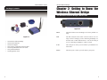
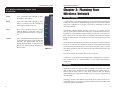
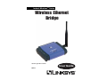
Instant WirelessTM Series
Wireless Ethernet
Bridge
Use this guide to install:
WET11
User Guide
COPYRIGHT & TRADEMARKS
Copyright © 2002 Linksys, All Rights Reserved. Instant Wireless is a trademark of
Linksys. Linksys is a registered trademark of Linksys. Microsoft, Windows, and the
Windows logo are registered trademarks of Microsoft Corporation. All other trademarks
and brand names are the property of their respective proprietors.
LIMITED WARRANTY
Linksys guarantees that every Wireless Ethernet Bridge will be free from physical defects
in material and workmanship for one year from the date of purchase, when used within
the limits set forth in the Specifications section of this User Guide. If the product proves
defective during this warranty period, call Linksys Technical Support in order to obtain a
Return Authorization Number. BE SURE TO HAVE YOUR PROOF OF PURCHASE AND A
BARCODE FROM THE PRODUCT’S PACKAGING ON HAND WHEN CALLING. RETURN
REQUESTS CANNOT BE PROCESSED WITHOUT PROOF OF PURCHASE. When returning a product, mark the Return Authorization Number clearly on the outside of the package and include a copy of your original proof of purchase. All customers located outside of the United States of America and Canada shall be held responsible for shipping
and handling charges.
IN NO EVENT SHALL LINKSYS’S LIABILITY EXCEED THE PRICE PAID FOR THE PRODUCT FROM DIRECT, INDIRECT, SPECIAL, INCIDENTAL, OR CONSEQUENTIAL DAMAGES RESULTING FROM THE USE OF THE PRODUCT, ITS ACCOMPANYING SOFTWARE, OR ITS DOCUMENTATION. LINKSYS DOES NOT OFFER REFUNDS FOR ANY
PRODUCT. Linksys makes no warranty or representation, expressed, implied, or statutory, with respect to its products or the contents or use of this documentation and all
accompanying software, and specifically disclaims its quality, performance, merchantability, or fitness for any particular purpose. Linksys reserves the right to revise or
update its products, software, or documentation without obligation to notify any individual or entity. Please direct all inquiries to:
Linksys P.O. Box 18558, Irvine, CA 92623.
FCC STATEMENT
This Wireless Ethernet Bridge has been tested and complies with the specifications for a
Class B digital device, pursuant to Part 15 of the FCC Rules. These limits are designed to
provide reasonable protection against harmful interference in a residential installation. This
equipment generates, uses, and can radiate radio frequency energy and, if not installed
and used according to the instructions, may cause harmful interference to radio communications. However, there is no guarantee that interference will not occur in a particular installation. If this equipment does cause harmful interference to radio or television reception,
which is found by turning the equipment off and on, the user is encouraged to try to correct the interference by one or more of the following measures:
•
•
•
•
Reorient or relocate the receiving antenna
Increase the separation between the equipment or devices
Connect the equipment to an outlet other than the receiver’s
Consult a dealer or an experienced radio/TV technician for assistance
FCC Radiation Exposure Statement
This equipment complies with FCC radiation exposure limits set forth for an uncontrolled
environment. This equipment should be installed and operated with minimum distance
20cm between the radiator and your body.
UG-WET11-072302C JL
Instant WirelessTM Series
Table of Contents
Chapter 1: Introduction
The Linksys Wireless Ethernet Bridge
Features
Package Contents
1
1
1
2
Chapter 2: Getting to Know the Wireless Ethernet
Bridge
3
The Wireless Ethernet Bridge’s Back Panel
3
The Wireless Ethernet Bridge’s Front Panel LEDs
4
Chapter 3: Planning Your Wireless Network
Network Topology
Roaming
Ad-Hoc versus Infrastructure Mode
5
5
5
6
Chapter 4: Connecting the Wireless Ethernet
Bridge
8
Wireless Ethernet Bridge
Chapter
1: Introduction
r
The Linksys Wireless Ethernet Bridge
Tailor-made for the home or small office network, the Wireless Ethernet Bridge
extends wireless connectivity to any Ethernet-ready network device, such as a
printer, scanner, desktop or notebook PC. The Wireless Ethernet Bridge simply
and efficiently transmits data between your wired Ethernet and wireless networks.
The Wireless Ethernet Bridge gives you the freedom to place any standard network resource virtually anywhere in your office.
Based on signal strength, it dynamically shifts between 11, 5.5, 2, and 1Mbps
network speeds for maximum availability and reliability of connection. So
you’ve got the flexibility and performance you need from your wireless network.
Features
Chapter 5: Setting Up the Wireless Ethernet
Bridge
9
•
•
•
•
•
Chapter 6: Using the Wireless Ethernet
Web-Based Utility
Overview
Starting the Web-Based Utility
Configuring the Wireless Ethernet Bridge
17
17
17
19
Appendix A: Troubleshooting
Common Problems and Solutions
Frequently Asked Questions
28
28
29
•
Appendix B: Glossary
33
Appendix C: Specifications
Environmental
38
39
•
•
•
•
Appendix D: Warranty Information
40
•
Appendix E: Contact Information
41
•
•
An All-in-One Wireless Solution for Any Ethernet-Ready Network Device
Interoperable with 802.11b (DSSS) 2.4GHz-Compliant Equipment
No Additional Drivers Are Needed
Up to 11 Mbps High-Speed Transfer Rate
Dynamically Shifts between 11, 5.5, 2, and 1Mbps for Maximum
Adaptability
Assurance of Constant Connection via Direct Sequence Spread Spectrum
(DSSS)
Conveniently Eliminates Cables and Network Wires Used by Network
Devices
Equipped with One Standard 10Base-T Interface for Connection with Any
Ethernet-Ready Networked Resource
Supports up to 50 Remote Clients
Capable of up to 128-Bit WEP Encryption
Setup Wizard for Easy Installation
Free Technical Support—24 Hours a Day, 7 Days a Week, Toll-Free US
Calls
1-Year Limited Warranty
1
Instant WirelessTM Series
Wireless Ethernet Bridge
Chapter 2: Getting to Know the
Wireless Ethernet Bridge
Package Contents
The Wireless Ethernet Bridge’s Back Panel
Figure 2-1
Figure 1-1
•
•
•
•
•
•
•
2
One Wireless Ethernet Bridge
One External Antenna
One Power Adapter
One Category 5 Ethernet Network Cable
One Setup CD-ROM with User Guide
One Quick Installation
One Registration Card
Reset
The Reset button resets the Bridge to its factory default settings.
X-II
The X-II selection switch offers a choice between two settings. Use the X setting if you are connecting the Bridge to a
network card or other Ethernet device. Use the II setting if
you are connecting the Bridge to a hub or switch.
LAN
The LAN port is where you will connect your Ethernet network cable.
Power
The Power port is where you will connect your power.
3
Instant WirelessTM Series
Wireless Ethernet Bridge
Chapter 3: Planning Your
Wireless Network
The Wireless Ethernet Bridge’s Front
Panel LEDs
PWR
Green. The PWR LED will light up when
the Bridge is powered on.
Network
Network Topology
Topology
DIAG
Green. The DIAG LED will light up when
there is a connection error. Re-establish the
connection to eliminate the error.
A wireless LAN is exactly like a regular LAN, except that each network device
in the LAN uses a Wireless Ethernet Bridge to connect to the network without
using wires. Computers in a wireless LAN must be configured to share the
same radio channel.
LAN
Green. The LAN LED will be lit steadily
when the Bridge is connected to the LAN.
The LED will blink when there is LAN traffic.
WLAN
Green. The WLAN LED indicates the status
of the link to the wireless local area network
(WLAN). The WLAN LED will be lit
steadily when the Bridge is connected to the
WLAN. The LED will blink when there is
WLAN traffic.
The Wireless Ethernet Bridge provides LAN access for wireless network
devices. An integrated wireless and wired LAN is called an Infrastructure configuration. A group of Wireless Ethernet Bridge users and an access point compose a Basic Service Set (BSS). Each PC equipped with an Wireless Ethernet
Bridge in a BSS can talk to any computer in a wired LAN infrastructure via the
Bridge.
Figure 2-2
An infrastructure configuration extends the accessibility of a Wireless Ethernet
Bridge to a wired LAN, and doubles the effective wireless transmission range
for two Wireless Ethernet Bridge PCs. Since the access point is able to forward
data within its BSS, the effective transmission range in an infrastructure LAN
is doubled.
The use of a unique ID in a Basic Service Set is essential.
The Wireless LAN infrastructure configuration is appropriate for enterprisescale wireless access to a central database, or as a wireless application for
mobile users.
Roaming
Infrastructure mode also supports roaming capabilities for mobile users. More
than one BSS can be configured as an Extended Service Set (ESS). This continuous network allows users to roam freely within an ESS. All Wireless
Ethernet Bridge PCs within one Extended Service Set must be configured with
the same SSID.
Selecting a feasible radio channel and optimum access point position is recommended. Proper access point positioning combined with a clear radio signal
will greatly enhance performance.
4
5
Instant WirelessTM Series
Ad-Hoc versus Infrastructure Mode
Unlike wired networks, wireless networks have two different modes in which
they may be set up: Infrastructure and Ad-Hoc. Choosing between these two
modes depends on whether or not the wireless network needs to share data or
peripherals with a wired network or not.
If the computers on the wireless network need to be accessible by a wired network or need to share a peripheral, such as a printer, with the wired network
computers, the wireless network should be set up in the Infrastructure mode.
The basis of Infrastructure mode centers around an access point, which serves
as the main point of communications in a wireless network (see Figure 3-1).
Access points transmit data to PCs equipped with wireless network card, which
can roam within a certain radial range of the access point. Multiple access
points can be arranged to work in succession to extend the roaming range, and
can be set up to communicate with your Ethernet hardware as well.
Wireless Ethernet Bridge
If the wireless network is relatively
small and needs to share resources
only with the other computers on the
wireless network, then the Ad-Hoc
mode can be used. Ad-Hoc mode
allows computers equipped with
wireless transmitters and receivers to
communicate directly with each
other, eliminating the need for an
access point. The drawback of this
mode is that in Ad-Hoc mode, wireless-equipped computers are not able
to communicate with computers on a
Figure 3-2
wired network. And, of course, communication between the wireless-equipped computers is limited by the distance and
interference directly between them.
Figure 3-2 shows a typical scenario of four Wireless Ethernet Bridges in ad-hoc
mode. Figure 3-3 shows a typical wireless bridging scenario using two Wireless
Ethernet Bridges. Each wireless network is connected to a Wireless Ethernet
Bridge through a switch. A separate notebook computer is equipped with a
wireless PC card and can communicate with both wireless networks as long as
it has the same SSID and channel as both wireless networks.
Figure 3-3
Figure 3-1
6
7
Instant WirelessTM Series
Wireless Ethernet Bridge
Chapter 4: Connecting the
Wireless Ethernet Bridge
Chapter 5: Setting Up the
Wireless Ethernet Bridge
1. Plug the included Ethernet network cable into the LAN port on the back
panel of the Bridge.
Now that you’ve connected the Wireless Ethernet Bridge to your wired network, you are ready to set it up. The Setup Wizard will guide you through all
the steps necessary.
1. Insert the Setup Wizard CD-ROM into your PC’s CD-ROM drive. The
Setup Utility should run automatically, and the screen in Figure 5-1 should
appear. If it does not, click the Start button and choose Run. In the field
that appears, enter D:\setup.exe (where “D” is the letter of your CD-ROM
drive).
Figure 4-1
2. The X-II selection switch offers a choice between two settings. Slide the
X-II selection switch to the X position if you are connecting the Bridge to a
network card or other Ethernet device. Slide the X-II selection switch to the
II position if you are connecting the Bridge to a hub or switch.
3. Plug the other end of the Ethernet network cable into the RJ-45 port on the
PC you wish to use to configure the Bridge.
4. Plug the supplied power cable into the Power port on the back panel of the
Bridge. Then plug the other end into an electrical outlet.
5. Proceed to the next section, “Chapter 5: Setting Up the Wireless Ethernet
Bridge.”
6. After configuration, unplug the Ethernet network cable from the PC, and
plug it into the RJ-45 port on the Ethernet-ready network device you wish
to add to the wireless network.
The hardware installation is complete.
8
Figure 5-1
Click the Setup button to continue using the Setup Wizard. Click the User
Guide button to open the pdf version of this User Guide. Click the Linksys
Web button to access the Linksys website using an active Internet connection. Click the Exit button to exit the Setup Wizard.
9
Instant WirelessTM Series
2. The screen shown in Figure 5-2 shows the two ways to configure the Bridge
using this Setup Wizard. Optimally, you should perform this setup through
a PC on your wired network. You can also set up the Bridge through one of
the PCs on your wireless network. Click the Next button to continue or the
Exit button to exit the Setup Wizard.
Wireless Ethernet Bridge
4. For security purposes, you will be asked for your user name and password
in order to access the Bridge. In lowercase letters, enter admin in the
Password field (later you can change the password through the Web-Based
Utility). Click the Yes button to continue or the No button to return to the
previous screen.
Figure 5-4
Figure 5-2
3. The screen shown in Figure 5-3 displays a list of Wireless Ethernet Bridges
on your network, along with the status information for each Bridge. (If you
have only one Bridge on your network, it will be the only one displayed.)
Select the Bridge you are currently installing by clicking its name in the
Selection box. Write down the IP address of the Wireless Ethernet Bridge,
so you can use it to access the Web-Based Utility later. Click the Yes button to continue or the Exit button to exit the Setup Wizard.
5. The screen shown in Figure 5-5 shows a choice of two wireless modes.
Click the Infrastructure Mode radio button if you want your wireless
computers to network with computers on your wired network using a wireless access point. Click the Ad-Hoc Mode radio button if you want multiple wireless computers to network directly with each other. Do not use the
Ad-Hoc mode if you want to network your wireless computers with computers on your wired network. Click the Next button to continue or the
Back button to return to the previous screen.
Figure 5-5
Figure 5-3
10
11
Instant WirelessTM Series
6. The Basic Settings screen will now appear. Enter your wireless network’s
SSID, and select the Channel at which the network broadcasts its wireless
signal. Enter a unique Bridge Name for the Bridge. Then click the Next
button to continue or the Back button to return to the previous screen.
•
SSID - The SSID is the unique name shared among all points in a wireless
network. The SSID must be identical for all points in the wireless network.
It is case-sensitive and must not exceed 32 characters (use any of the characters on the keyboard). Make sure this setting is the same for all points in
your wireless network.
•
Channel - Select the appropriate channel from the list provided to correspond with your network settings, between 1 and 11 (in North America). All
points in your wireless network must use the same channel in order to function correctly.
•
Bridge Name - You may assign any name to the Bridge. Unique, memorable names are helpful, especially if you are using multiple bridges on the
same network.
Wireless Ethernet Bridge
7. The IP Settings screen will appear next, shown in Figure 5-7. If your network has a DHCP server, click the radio button next to Automatically
obtain an IP address (DHCP). Click the Next button to continue or the
Back button to return to the previous screen. Then proceed to step 8.
If your network does not have a DHCP server, click the radio button beside
Set IP configuration manually to select this option. Enter an IP Address,
IP Mask, and Gateway appropriate to your network. You must specify an IP
address on this screen. If you are unsure about the IP Mask and Gateway, it
is better to leave these two fields blank. Click the Next button to continue or
the Back button to return to the previous screen. Then proceed to step 8.
•
IP Address - This IP address must be unique to your network. Because this
is a private IP address, there is no need to purchase a separate IP address
from your Internet Service Provider (ISP).
•
IP Mask - The Bridge’s IP Mask (also known as Subnet Mask) must be the
same as your Ethernet (wired) network.
•
Gateway - Enter the IP address of your network’s Gateway here.
Figure 5-6
Figure 5-7
12
13
Instant WirelessTM Series
8. The Security Settings screen, shown in Figure 5-8, appears next. Set the
Wired Equivalent Privacy (WEP) encryption for your wireless network by
selecting a WEP configuration method.
•
WEP (Disabled/64-bit WEP/128-bit WEP) - In order to utilize WEP
encryption, select 64-bit or 128-bit WEP from the drop-down menu. If you
do not want to use WEP encryption, choose Disabled (default). The
Bridge’s WEP encryption is unique to Linksys and may conflict with other
manufacturers’ WEP encryption.
Wireless Ethernet Bridge
9b. Leave the Passphrase field blank, and click the Next button to continue or
the Back button to return to the previous screen.
If you selected 64-bit WEP, you will see Figure 5-9 (you will see a similar
screen if you choose 128-bit WEP). Enter a WEP key. If you are using 64bit WEP encryption, then the key must consist of exactly 10 hexadecimal
characters in length. If you are using 128-bit WEP encryption, then the key
must consist of exactly 26 hexadecimal characters in length. Valid hexadecimal characters are “0”-“9” and “A”-“F”. Then click the Next button,
and proceed to step 10.
If you select 64-bit or 128-bit WEP, you can create a WEP key automatically or manually. Go to step 9a to generate a WEP key automatically. Go
to step 9b to create a WEP key manually.
Figure 5-9
Figure 5-8
10. The screen shown in Figure 5-10 allows you to review your settings. If these
settings are correct, click the Yes button to save these settings. If any of
these settings are wrong, click the Back button to make changes. Click the
Exit button to exit the Setup Wizard.
9a. Enter a passphrase.
•
Passphrase - This is the code used when logging a wireless device onto the
wireless network. The passphrase is case-sensitive and should not be longer
than 16 alphanumeric characters. Based upon the passphrase created by
you, WEP key settings are automatically generated. This passphrase is only
compatible with other Linksys wireless products.
Click the Next button to continue or the Back button to return to the previous screen. Then on the WEP Key Settings screen, you will see the automatically generated WEP key. Click the Next button, and proceed to step 10.
Figure 5-10
14
15
Instant WirelessTM Series
11. The configuration using the Setup Wizard is complete. To configure any
other Bridges on your network, run this Setup Wizard again. To exit the
Setup Wizard, click the Exit button.
Wireless Ethernet Bridge
Chapter 6: Using the Wireless
Ethernet Bridge Web-Based
Utility
Overview
The Bridge is designed to function properly after configuration using the Setup
Wizard. However, if you would like to change these settings or make more
advanced configuration changes, use your web browser and the Wireless
Ethernet Bridge Web-Based Utility. This chapter explains how to use the
Utility.
Starting the Web-Based Utility
Figure 5-11
Important: To activate the new settings, reset the Bridge. Turn off
the Bridge, and wait a few seconds. Then power on the Bridge.
1. Open your web browser, and enter the IP address of the Wireless Ethernet
Bridge (see Figure 5-3). Press the Enter key, and the screen shown in
Figure 6-1 will appear. In lowercase letters, enter admin in the Password
field (the default password is admin). Click the OK button. You can set a
new password on the Admin screen later.
The Wireless Ethernet Bridge is now successfully set up for your network.
After you have reset the Bridge, unplug the Ethernet network cable from the
PC, and plug it into the RJ-45 port of the Ethernet-ready network device you
wish to add to the wireless network.
For more advanced configuration, keep the Bridge plugged into the PC,
and proceed to “Chapter 6: Using the Wireless Ethernet Bridge WebBased Utility.”
Figure 6-1
16
17
Instant WirelessTM Series
2. The INFO screen of the Bridge’s Utility will appear.
Wireless Ethernet Bridge
Configuring the Wireless Ethernet Bridge
The Utility provides five screens for configuring the Bridge’s settings.
The Utility is comprised of five screens that allows you to configure different
settings.
•
•
•
•
•
Info screen - Displays the Bridge’s current settings.
Wireless screen - Use this tab to configure the wireless settings.
IP Addr screen - Enables you to configure the IP address settings.
Admin screen - Use this tab to change the password, reboot the Bridge, or
reset all settings to factory defaults.
Help screen - Provides explanations of various configuration settings, as
well as contact information for Linksys.
INFO
The INFO screen displays the Bridge’s current status and settings.
Figure 6-2
Figure 6-3
18
19
Instant WirelessTM Series
•
SSID - Displays the wireless network’s current SSID. If it displays “nonspec,” then the Bridge is not connected to any wireless network.
•
Channel - Displays the Bridge’s current channel number.
•
BSSID - Displays the wireless network’s current BSSID. For infrastructure
mode, the BSSID is the MAC address of the access point to which the
Bridge is connected.
•
Transmission Rate - Displays the transmission rate of the current connection.
•
Link Quality (%) - When the Bridge is connected to a wired LAN, the percentage of connection integrity is displayed. (This is not available when
using an ad-hoc or peer-to-peer connection.)
•
MAC Address - Displays the Bridge’s MAC address.
•
IP Address - Displays the Bridge’s IP address.
•
Firmware Revision - Displays the version number of the Bridge’s
firmware.
Wireless Ethernet Bridge
WIRELESS
The Wireless screen allows you to configure your wireless settings. Any new
settings will not take effect until the Bridge is rebooted. (To reboot the Bridge,
click the Admin tab, and click the Reboot button.)
The “Results of the most recent scan” section displays information about all
devices detected by the Bridge.
•
SSID - Displays the current SSID of a network device.
•
MAC Address - Displays the wireless MAC address of a network device.
•
Channel - Displays the current channel number of a network device.
•
Signal Strength (%) - Displays the total available amount of signal measured above the noise. (This is not available when using an ad-hoc or peerto-peer connection.)
•
Mode - Displays the operating mode of a network device.
Note: You may have to refresh this page to see any new settings.
Figure 6-4
20
21
Instant WirelessTM Series
•
Operating mode - Select the LAN mode, either Ad-hoc or Infrastructure.
•
SSID - Displays the current Service Set Identification. The default SSID is
linksys.
•
Channel - Enables you to select a transmission channel. It is valid only
when the Bridge is operating in Ad-hoc mode. All points on the network
must be set to the same channel.
•
Transmission rate - Displays a list of transfer rates (Megabits per second):
1, 2, 5.5, 11, or Automatic. The default setting, Automatic, allows the
Bridge to automatically adjust the transfer speed for optimal performance
and the longest operating range.
•
Access point density (for infrastructure mode only) - Enables you to specify how many access points are near the Bridge. Use this setting to reduce
channel overlap and interference.
•
WEP keys 1-4 - Enables you to create an encryption scheme for wireless
LAN transmissions. Manually enter a set of values for each key. 128-bit
encryption requires more system resources than 64-bit encryption. Use 64bit encryption for better performance.
If you are using 64-bit WEP encryption, then each key must consist of
exactly 10 hexadecimal characters in length.
If you are using 128-bit WEP encryption, then each key must consist of
exactly 26 hexadecimal characters in length.
Valid hexadecimal characters are “0”-“9” and “A”-“F”. A WEP key field
that is left blank is a key of all zeroes.
•
WEP key to use - Sets which WEP key (1-4) to use when sending data.
Make sure the receiver is using the same key.
•
Deny unencrypted data - When this box is checked, the Bridge ignores
unencrypted data transmissions.
•
When the Bridge is connected in an infrastructure network environment, a
list of nearby access points is displayed at the bottom of the INFO screen.
Shared key authentication - Two authentication modes are available.
When the box is checked, shared key authentication is enabled. You must set
a WEP key to exchange data. When the box is unchecked, there is public
access to this Bridge.
•
WEP enabled - Allows you to enable or disable Wired Equivalent Privacy
(WEP) for encryption. You must check this box to enable WEP encryption.
Click the Apply button to save your changes, or click the Cancel button to cancel your changes.
•
WEP key length - Once WEP enabled is checked, choose 64-bit or 128-bit
WEP encryption here. Some access points do not support 128-bit encryption.
•
Passphrase - This is the code used when logging a wireless device onto the
wireless network. The passphrase is case-sensitive and should not be longer
than 16 alphanumeric characters. WEP key settings are based upon the
passphrase created by you. This passphrase is compatible with Linksys
wireless products only.
Low: 1-2 nearby access points
Medium: 3-4 nearby access points
High: 5 or more nearby access points
22
Wireless Ethernet Bridge
Note: You may have to refresh this page to see any new settings.
23
Instant WirelessTM Series
Wireless Ethernet Bridge
IP ADDR
•
IP Gateway - Sets the IP address of your network’s Gateway.
The IP Addr screen is used to configure the IP address used by the web and
TFTP servers running on the Bridge. For static mode, the IP address settings
are given on-screen. For DHCP mode, the settings on the IP Addr screen will
be overridden by a DHCP server on your network. Any new settings will not
take effect until the Bridge is rebooted. (To reboot the Bridge, click the Admin
tab, and click the Reboot button.)
•
Device Name - Sets the Bridge’s name. The default name is Linksys
WET11.
•
Allow Firmware Upgrade - When the box is checked, the Bridge accepts
firmware upgrades.
Click the Apply button to save your changes, or click the Cancel button to cancel your changes.
Note: You may have to refresh this page to see any new settings.
Figure 6-5
24
•
IP Address Mode - Enables you to select the IP address mode: Static or
DHCP (Dynamic Host Configuration Protocol). DHCP mode enables the
DHCP server on your network to override the current IP address settings.
•
IP Address - Sets the Bridge’s IP address.
•
IP Subnet - Sets the Bridge’s Subnet Mask address.
25
Instant WirelessTM Series
Wireless Ethernet Bridge
ADMIN
HELP
The Admin screen allows you to change the password, reboot the Bridge, or
reset all settings to their factory defaults. If you have changed any settings, it is
necessary to reboot the Bridge for the new settings to take effect (click the
Reboot button). Any changes in these three settings: password, device name,
and enabling uploads, however, are effective immediately.
The HELP screen offers additional explanations about the terms used on each
screen of the Utility, plus contact information for additional assistance.
Figure 6-6
•
Change password - Set or change the network password required to access
the utility. The default password is admin.
•
Reboot WET11 - After you have made changes through any of the screens,
click this button to enable the new settings.
•
Reset to factory defaults - Resets all configuration settings to their default
values.
Figure 6-7
Note: You may have to refresh this page to see any new settings.
26
27
Instant WirelessTM Series
Appendix A: Troubleshooting
Wireless Ethernet Bridge
5. The Web-Based Utility won’t open.
Make sure that you have a LAN card (also known as a network adapter)
installed on the PC so you can use the Web-Based Utility.
Common Problems and Solutions
This section provides possible solutions to problems regarding the installation and
operation of the Wireless Ethernet Bridge. If you can’t find an answer here, check
the Linksys website at www.linksys.com.
1. I can’t connect to the access point.
Open the Web-Based Utility. Click the Wireless tab and perform the following steps:
• Verify that the operating mode is set to Infrastructure mode.
• Make sure that the SSID is the same as the SSID of the access point.
• Make sure that all of the WEP settings are the same as the WEP settings
of the access point.
2. I don’t know how to change the Bridge’s IP address.
You have two ways to change the Bridge’s IP address.
• Open the Web-Based Utility. Click the IP Addr tab, and change the IP
address there.
• If you encounter problems, power the Bridge off and on again, or push the
Reset button. Then try to change the IP address again.
3. The Bridge-enabled PC won’t communicate with a wireless-enabled PC or
printer.
Perform the following steps:
• Check that the wireless-enabled PC or printer is on the same wireless network as the PC using the Bridge.
• Make sure that the SSID and operating mode are the same for all devices
connected to the same wireless network.
• If the wireless LAN settings are okay, make sure that all the devices are
on the same IP network.
4. The Web-Based Utility doesn’t detect the Bridge.
Make sure that the Ethernet cable is properly connected and that the LAN
LED is lit. If the LED is not lit, change the position of the X-II selection
switch on the Bridge’s rear panel. Use the X setting if you are connecting
the Bridge to a network card or other Ethernet device. Use the II setting if
you are connecting the Bridge to a hub or switch.
28
6. The Web-Based Utility does not recognize my password.
The password is case-sensitive. Make sure you are using the correct case(s)
when entering the password.
If you forget your password, you can push the Bridge’s Reset button. This
will reset the password to the default setting; however, all other Bridge settings will be reset to the factory defaults as well. To use the default settings,
leave the User Name field blank, and enter admin in the Password field.
Frequently Asked Questions
Can I run an application from a remote computer over the wireless network?
This will depend on whether or not the application is designed to be used over
a network. Consult the application’s user guide to determine if it supports operation over a network.
Can I play multiplayer games with other users of the wireless network?
Yes, as long as the game supports multiple players over a LAN. Refer to the
game’s user guide for more information.
What is the IEEE 802.11b standard?
It is one of the IEEE standards for wireless networks. The 802.11b standard
allows wireless networking hardware from different manufacturers to communicate, provided that the hardware complies with the 802.11b standard. The
802.11b standard states a maximum data transfer rate of 11Mbps and an operating frequency of 2.4GHz.
What IEEE 802.11b features are supported?
The product supports the following IEEE 802.11 functions:
•
CSMA/CA plus Acknowledge protocol
•
Multi-Channel Roaming
•
Automatic Rate Selection
•
RTS/CTS feature
•
Fragmentation
•
Power Management
29
Instant WirelessTM Series
What is ad-hoc mode?
When a wireless network is set to ad-hoc mode, the wireless-equipped computers are configured to communicate directly with each other. The ad-hoc
wireless network will not communicate with any wired network.
What is infrastructure mode?
When a wireless network is set to infrastructure mode, the wireless network is
configured to communicate with a wired network through a wireless access
point.
What is roaming?
Roaming is the ability of a portable computer user to communicate continuously while moving freely throughout an area greater than that covered by a single wireless network access point. Before using the roaming function, the
workstation must make sure that it is the same channel number as the wireless
network access point of the dedicated coverage area.
To achieve true seamless connectivity, the wireless LAN must incorporate a
number of different functions. Each node and wireless network access point,
for example, must always acknowledge receipt of each message. Each node
must maintain contact with the wireless network even when not actually transmitting data. Achieving these functions simultaneously requires a dynamic RF
networking technology that links wireless network access points and nodes. In
such a system, the user’s end node undertakes a search for the best possible
access to the system. First, it evaluates such factors as signal strength and quality, as well as the message load currently being carried by each wireless network access point and the distance of each wireless network access point to the
wired backbone. Based on that information, the node next selects the right
wireless network access point and registers its address. Communications
between end node and host computer can then be transmitted up and down the
backbone.
As the user moves on, the end node’s RF transmitter regularly checks the system to determine whether it is in touch with the original wireless network
access point or whether it should seek a new one. When a node no longer
receives acknowledgment from its original wireless network access point, it
undertakes a new search. Upon finding a new wireless network access point, it
then re-registers, and the communication process continues.
30
Wireless Ethernet Bridge
What is ISM band?
The FCC and their counterparts outside of the U.S. have set aside bandwidth
for unlicensed use in the ISM (Industrial, Scientific and Medical) band.
Spectrum in the vicinity of 2.4 GHz, in particular, is being made available
worldwide. This presents a truly revolutionary opportunity to place convenient
high speed wireless capabilities in the hands of users around the globe.
What is Spread Spectrum?
Spread Spectrum technology is a wideband radio frequency technique developed by the military for use in reliable, secure, mission-critical communications systems. It is designed to trade off bandwidth efficiency for reliability,
integrity, and security. In other words, more bandwidth is consumed than in the
case of narrowband transmission, but the trade-off produces a signal that is, in
effect, louder and thus easier to detect, provided that the receiver knows the
parameters of the spread-spectrum signal being broadcast. If a receiver is not
tuned to the right frequency, a spread-spectrum signal looks like background
noise. There are two main alternatives, Direct Sequence Spread Spectrum
(DSSS) and Frequency Hopping Spread Spectrum (FHSS).
What is DSSS? What is FHSS? And what are their differences?
Frequency Hopping Spread Spectrum (FHSS) uses a narrowband carrier that
changes frequency in a pattern that is known to both transmitter and receiver.
Properly synchronized, the net effect is to maintain a single logical channel. To
an unintended receiver, FHSS appears to be short-duration impulse noise.
Direct Sequence Spread Spectrum (DSSS) generates a redundant bit pattern for
each bit to be transmitted. This bit pattern is called a chip (or chipping code).
The longer the chip, the greater the probability that the original data can be
recovered. Even if one or more bits in the chip are damaged during transmission, statistical techniques embedded in the radio can recover the original data
without the need for retransmission. To an unintended receiver, DSSS appears
as low power wideband noise and is rejected (ignored) by most narrowband
receivers.
Would the information be intercepted while transmitting on air?
Instant Wireless products feature two-fold protection in security. On the hardware side, as with Direct Sequence Spread Spectrum technology, it has the
inherent security feature of scrambling. On the software side, Instant Wireless
products offer the encryption function (WEP) to enhance security and access
control. Users can set it up depending upon their needs.
31
Instant WirelessTM Series
Can Instant Wireless products support file and printer sharing?
Instant Wireless products perform the same function as LAN products.
Therefore, Instant Wireless products can work with NetWare, Windows
NT/2000, or other LAN operating systems to support printer or file sharing.
What is WEP?
WEP is Wired Equivalent Privacy, a data privacy mechanism based on a 40/64
bit shared key algorithm, as described in the IEEE 802.11 standard.
Wireless Ethernet Bridge
Appendix B: Glossary
Ad-hoc Network - An ad-hoc network is a group of computers, each with a
wireless adapter, connected as an independent 802.11 wireless LAN. Ad-hoc
wireless computers operate on a peer-to-peer basis, communicating directly
with each other without the use of an access point. Ad-hoc mode is also
referred to as an Independent Basic Service Set (IBSS) or as peer-to-peer
mode, and is useful at a departmental scale or SOHO operation.
Default Gateway - The router used to forward all traffic that is not addressed
to a station within the local subnet.
DHCP (Dynamic Host Configuration Protocol) - A protocol that lets network
administrators centrally manage and automate the assignment of Internet
Protocol (IP) addresses in an organization's network. Using the Internet's set of
protocol (TCP/IP), each machine that can connect to the Internet needs a
unique IP address. When an organization sets up its computer users with a connection to the Internet, an IP address must be assigned to each machine.
Without DHCP, the IP address must be entered manually at each computer and,
if computers move to another location in another part of the network, a new IP
address must be entered. DHCP lets a network administrator supervise and distribute IP addresses from a central point and automatically sends a new IP
address when a computer is plugged into a different place in the network.
DHCP uses the concept of a “lease” or amount of time that a given IP address
will be valid for a computer. The lease time can vary depending on how long a
user is likely to require the Internet connection at a particular location. It’s especially useful in education and other environments where users change frequently. Using very short leases, DHCP can dynamically reconfigure networks
in which there are more computers than there are available IP addresses.
DHCP supports static addresses for computers containing Web servers that
need a permanent IP address.
DNS - The Domain Name System (DNS) is the way that Internet domain
names are located and translated into Internet Protocol (IP) addresses. A
domain name is a meaningful and easy-to-remember “handle” for an Internet
address.
32
33
Instant WirelessTM Series
DSSS (Direct-Sequence Spread Spectrum) - DSSS generates a redundant bit
pattern for all transmitted data. This bit pattern is called a chip (or chipping
code). Even if one or more bits in the chip are damaged during transmission,
statistical techniques embedded in the receiver can recover the original data
without the need for retransmission. To an unintended receiver, DSSS appears
as low power wideband noise and is rejected (ignored) by most narrowband
receivers. However, to an intended receiver (i.e. another wireless LAN endpoint), the DSSS signal is recognized as the only valid signal, and interference
is inherently rejected (ignored).
Dynamic IP Address - An IP address that is automatically assigned to a client
station in a TCP/IP network, typically by a DHCP server. Network devices that
serve multiple users, such as servers and printers, are usually assigned static IP
addresses.
ESS (Extended Service Set) - A set of more than two or more BSSs (multiple
access points) forming a single network.
FHSS (Frequency Hopping Spread Spectrum) - FHSS continuously changes
(hops) the carrier frequency of a conventional carrier several times per second
according to a pseudo-random set of channels. Because a fixed frequency is not
used, and only the transmitter and receiver know the hop patterns, interception
of FHSS is extremely difficult.
Firmware - Code that is written onto read-only memory (ROM) or programmable read-only memory (PROM). Once firmware has been written onto the
ROM or PROM, it is retained even when the device is turned off.
IEEE - The Institute of Electrical and Electronics Engineers. The IEEE
describes itself as “the world's largest technical professional society—promoting the development and application of electrotechnology and allied sciences
for the benefit of humanity, the advancement of the profession, and the wellbeing of our members.”
The IEEE fosters the development of standards that often become national and
international standards. The organization publishes a number of journals, has
many local chapters, and has several large societies in special areas, such as the
IEEE Computer Society.
34
Wireless Ethernet Bridge
IEEE 802.11b - One of the IEEE standards for wireless networks. The 802.11b
standard allows wireless networking hardware from different manufacturers to
communicate, provided that the hardware complies with the 802.11b standard.
The 802.11b standard states a maximum data transfer rate of 11Mbps and an
operating frequency of 2.4GHz.
Infrastructure Network - An infrastructure network is a group of computers
or other devices, each with a wireless adapter, connected as an 802.11 wireless
LAN. In infrastructure mode, the wireless devices communicate with each
other and to a wired network by first going through an access point. An infrastructure wireless network connected to a wired network is referred to as a
Basic Service Set (BSS). A set of two or more BSS in a single network is
referred to as an Extended Service Set (ESS). Infrastructure mode is useful at
a corporation scale, or when it is necessary to connect the wired and wireless
networks.
IP Address - In the most widely installed level of the Internet Protocol (IP)
today, an IP address is a 32-binary digit number that identifies each sender or
receiver of information that is sent in packets across the Internet. When you
request an HTML page or send e-mail, the Internet Protocol part of TCP/IP
includes your IP address in the message (actually, in each of the packets if more
than one is required) and sends it to the IP address that is obtained by looking
up the domain name in the Uniform Resource Locator you requested or in the
e-mail address you're sending a note to. At the other end, the recipient can see
the IP address of the Web page requester or the e-mail sender and can respond
by sending another message using the IP address it received.
IPCONFIG - A utility that provides for querying, defining and managing IP
addresses within a network. A commonly used utility, under Windows NT and
2000, for configuring networks with static IP addresses.
ISP - An ISP (Internet service provider) is a company that provides individuals
and companies access to the Internet and other related services such as website
building and virtual hosting.
LAN - A local area network (LAN) is a group of computers and associated
devices that share a common communications line and typically share the
resources of a single processor or server within a small geographic area (for
example, within an office building).
35
Instant WirelessTM Series
MAC Address - The MAC (Media Access Control) address is a unique number assigned by the manufacturer to any Ethernet networking device, such as a
network adapter, that allows the network to identify it at the hardware level.
Wireless Ethernet Bridge
Network Mask - Also known as the “Subnet Mask.”
TCP (Transmission Control Protocol) - A method (protocol) used along with
the IP (Internet Protocol) to send data in the form of message units (datagram)
between network devices over a LAN or WAN. While IP takes care of handling
the actual delivery of the data (routing), TCP takes care of keeping track of the
individual units of data (called packets) that a message is divided into for efficient delivery over the network. TCP is known as a "connection oriented" protocol due to requiring the receiver of a packet to return an acknowledgment of
receipt to the sender of the packet resulting in transmission control.
PCMCIA - The PCMCIA (Personal Computer Memory Card International
Association) is an industry group organized in 1989 to promote standards for a
credit card-size memory or I/O device that would fit into a personal computer,
usually a notebook or laptop computer.
TCP/IP (Transmission Control Protocol/Internet Protocol) - The basic communication language or set of protocols for communications over a network
(developed specifically for the Internet). TCP/IP defines a suite or group of
protocols and not only TCP and IP.
Ping (Packet INternet Groper) - An Internet utility used to determine whether
a particular IP address is online. It is used to test and debug a network by sending out a packet and waiting for a response.
UDP (User Datagram Protocol) - A method (protocol) used along with the IP
(Internet Protocol) to send data in the form of message units (datagram)
between network devices over a LAN or WAN. While IP takes care of handling
the actual delivery of the data (routing), UDP takes care of keeping track of the
individual units of data (called packets) that a message is divided into for efficient delivery over the network. UDP is known as a “connection-less” protocol
due to NOT requiring the receiver of a packet to return an acknowledgment of
receipt to the sender of the packet (as opposed to TCP).
mIRC - mIRC runs under Windows and provides a graphical interface for logging onto IRC servers and listing, joining, and leaving channels.
RJ-45 - A connector similar to a telephone connector that holds up to eight
wires, used for connecting Ethernet devices.
Roaming - In an infrastructure mode wireless network, this refers to the ability to move out of one access point's range and into another and transparently
reassociate and reauthenticate to the new access point. This reassociation and
reauthentication should occur without user intervention and ideally without
interruption to network connectivity. A typical scenario would be a location
with multiple access points, where users can physically relocate from one area
to another and easily maintain connectivity.
SOHO (Small Office/Home Office) - Refers to any small office or home
office environment.
Static IP Address - A permanent IP address that is assigned to a node in a
TCP/IP network.
WEP (Wired Equivalent Privacy) - A data privacy mechanism based on a 64bit shared key algorithm, as described in the IEEE 802.11 standard.
WINIPCFG - Configuration utility based on the Win32 API for querying,
defining, and managing IP addresses within a network. A commonly used utility, under Windows 95, 98, and Millennium, for configuring networks with
static IP addresses.
WLAN - A group of computers and associated devices that communicate with
each other wirelessly. If set to infrastructure mode, the WLAN can communicate with a wired network through a wireless network access point.
Subnet Mask - The method used for splitting IP networks into a series of subgroups, or subnets. The mask is a binary pattern that is matched up with the IP
address to turn part of the host ID address field into a field for subnets.
36
37
Instant WirelessTM Series
Appendix C: Specifications
38
Wireless Ethernet Bridge
Environmental
Dimensions
4.94" x 3.70" x 1.22"
(125.5 mm x 94 mm x 31 mm)
IEEE 802.11b, IEEE 802.3
Unit Weight
7.1 oz. (0.2 kg)
Channels
11 Channels (US, Canada)
13 Channels (Europe)
Power
5V DC
Certifications
FCC Class B, CE Mark
Ports
One RJ-45 (10BaseT)
One Reverse SMA Antenna
Operating Temp.
32°F to 122°F (0°C to 50°C)
Transmit
19 dBm
Storage Temp.
-13°F to 158°F (-25°C to 70°C)
Receive Sensitivity
-83 dBm (typical)
Operating Humidity 10% to 90%, Non-Condensing
Modulation
DSS, BPSK, QPSK, CCK
Storage Humidity
LEDs
Power, LAN, WLAN, Diag
Network Protocol
TCP/IP
Model Number
WET11
Standard
10% to 90%, Non-Condensing
39
Instant WirelessTM Series
Wireless Ethernet Bridge
Appendix D: Warranty Information
Appendix E: Contact Information
BE SURE TO HAVE YOUR PROOF OF PURCHASE AND A BARCODE
FROM THE PRODUCT’S PACKAGING ON HAND WHEN CALLING.
RETURN REQUESTS CANNOT BE PROCESSED WITHOUT PROOF OF
PURCHASE.
For help with the installation or operation of this product, contact Linksys
Technical Support at one of the phone numbers or Internet addresses below.
IN NO EVENT SHALL LINKSYS’S LIABILITY EXCEED THE PRICE
PAID FOR THE PRODUCT FROM DIRECT, INDIRECT, SPECIAL, INCIDENTAL, OR CONSEQUENTIAL DAMAGES RESULTING FROM THE
USE OF THE PRODUCT, ITS ACCOMPANYING SOFTWARE, OR ITS
DOCUMENTATION. LINKSYS DOES NOT OFFER REFUNDS FOR ANY
PRODUCT.
Sales Information
Technical Support
RMA Issues
Fax
Email
Web
FTP Site
800-546-5797 (LINKSYS)
800-326-7114
949-271-5461
949-265-6655
[email protected]
http://www.linksys.com
ftp.linksys.com
LINKSYS OFFERS CROSS SHIPMENTS, A FASTER PROCESS FOR PROCESSING AND RECEIVING YOUR REPLACEMENT. LINKSYS PAYS
FOR UPS GROUND ONLY. ALL CUSTOMERS LOCATED OUTSIDE OF
THE UNITED STATES OF AMERICA AND CANADA SHALL BE HELD
RESPONSIBLE FOR SHIPPING AND HANDLING CHARGES. PLEASE
CALL LINKSYS FOR MORE DETAILS.
40
41
http://www.linksys.com
© Copyright 2002 Linksys, All Rights Reserved.