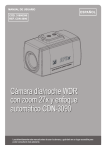
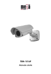
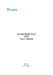
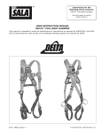
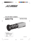
1
Installation and Operating Manual
1/4” Day/Night Camera, Outdoor Housing, 22x Zoom
VKC-1416B-/PP
Contents
1. Safety Instructions............................................................................................................................................................................................................................ 3
2. Introduction...................................................................................................................................................................................................................................... 3
2.1 General Description................................................................................................................................................................................................................. 3
2.2 Parts Supplied......................................................................................................................................................................................................................... 3
3. Camera Installation........................................................................................................................................................................................................................... 4
3.1 Package Contents.................................................................................................................................................................................................................... 4
3.2 Operation Requirements.......................................................................................................................................................................................................... 4
3.3 Parts Name.............................................................................................................................................................................................................................. 5
3.4 Installation............................................................................................................................................................................................................................... 5
3.4.1 Installation 1 (Cable through the Wall with the Mount Base) . ...................................................................................................................................... 6
3.4.2 Instillation 2 (Using the Conduit Knockout punched with Mount Base).......................................................................................................................... 7
4. Connection........................................................................................................................................................................................................................................ 8
4.1 Colour Lead Wire & Colour Display Label.................................................................................................................................................................................. 8
4.2 External Day/Night Control & Zoom Preset Control................................................................................................................................................................... 9
4.3 Motoion Detection & Face Detection Control............................................................................................................................................................................ 9
4.4 RS-485 Connection ................................................................................................................................................................................................................ 9
4.5 Power Connection.................................................................................................................................................................................................................. 10
4.6 External A/D Key Control........................................................................................................................................................................................................ 10
5. Settings in the OSD Menu............................................................................................................................................................................................................... 11
5.1 OSD Main Screen.................................................................................................................................................................................................................. 11
5.2 Main Menu............................................................................................................................................................................................................................ 11
5.2.1 FOCUS...................................................................................................................................................................................................................... 11
5.2.2 WB (White Balance)................................................................................................................................................................................................... 11
5.2.3 AE (Auto Exposure).................................................................................................................................................................................................... 12
5.2.4 BLC/WDR.......................................................................................................................................................................................................................12
5.2.5 ALARM/MD/FD.......................................................................................................................................................................................................... 12
5.2.6 PRIVACY.................................................................................................................................................................................................................... 13
5.2.7 SPECIAL.................................................................................................................................................................................................................... 13
5.2.8 EFFECT..................................................................................................................................................................................................................... 13
5.2.9 CAM SET................................................................................................................................................................................................................... 14
6. Troubleshooting.............................................................................................................................................................................................................................. 14
7. Maintenance................................................................................................................................................................................................................................... 14
8. Specifications................................................................................................................................................................................................................................. 15
9. Dimensional Drawings...................................................................................................................................................................................................................... 16
Betriebsanleitung
Installation and Operating Instructions
Mode d’emploi
⇒
www.videor.com
www.eneo-security.com
Instrukcja instalacji i obsługi
1. Safety Instructions
•
Read these safety instructions and the operation manual first before you install and commission the camera.
•
Keep the manual in a safe place for later reference.
•
P rotect your camera from contamination with water and humidity to prevent it from permanent damage. Never switch the camera on when it gets wet. Have it checked at an authorized service center in this case.
•
Never operate the camera outside of the specifications as this may prevent the camera functioning.
•
Do not operate the cameras beyond their specified temperature, humidity or power ratings. Operate the camera only at a temperature range of -10°C to +50°C and at a humidity of max. 90%.
•
To disconnect the power cord of the unit, pull it out by the plug. Never pull the cord itself.
•
Pay attention when laying the connection cable and observe that the cable is not subject to heavy loads, kinks, or damage and no moisture can get in.
•
The warranty becomes void if repairs are undertaken by unauthorized persons. Do not open the camera housing.
•
Never point the camera towards the sun with the aperture open. This can destroy the sensor.
•
Installation, maintenance and repair have to be carried out only by authorized service centers.
Before opening the cover disconnect the unit from mains input.
•
The fitter is responsible for the system of protection being followed in accordance with the technical data, e.g. by sealing of the cable outlet with silicone.
•
Contact your local dealer in case of malfunction.
•
Only use original parts and original accessories from Videor E. Hartig GmbH.
•
Do not use strong or abrasive detergents when cleaning the dome. Use a dry cloth to clean the dome surface. In case the dirt is hard to remove, use a mild detergent and wipe gently.
•
During assembly, care must be taken to ensure that existing seals are correctly inserted and are not displaced as a result of assembly.
You must not continue to use damaged seals.
NOTE:This is a class A digital device. This digital device can cause harmful interference in a residential area; in this case the user may be required to take
appropriate corrective action at his/her own expense.
2. Introduction
2.1 General Description
The 22x AutoFocus Zoom WDR Day & Night Camera provides especially for closed circuit television (CCTV) and security surveillance application.
CAUTION: Use at the 12VDC adapter must provide the power consumption of above 500mA.
•
High Resolution Colour/B&W Camera
•
Integral 22x AF zoom lens / 16x digital zoom
•
Digital Signal Processing (DSP)
•
Enhanced dynamic range (WDR/EDR)
•
Digital image stabilization (DIS)
•
Digital noise reduction (DNR)
•
Programmable backlight compensation (BLC)
•
High speed shutter control (ESC+MES)
•
Adjustable low speed shutter control (DSS)
•
On-screen menu control
•
RS-232/RS-485 serial and voltage control interface
•
All-in-one: camera / lens / housing IP66
2.2 Parts Supplied
•
1/4” Colour camera VKC-1416B/IR
•
Screw set
•
Manual
3. Camera Installation
Installation of the camera must be performed by qualified service personnel in accordance with all local national electrical and mechanical codes must perform installation of the camera.
Perform the following steps to install the camera
3.1 Package Contents
•
Camera VKC-1416B/PP
•
Instruction Manual
•
Mounting Kit
3.2 Operation Requirements
RS-485
Multiplexer
J-Box
Camera 1
Camera 2
Video
RS-485
DVR / VCR
Keyboard
Monitor
RS-485
Typical System Configuration
Video
Camera 3 ...
3.3 Parts Name
Carefully remove the contents from the box, and verify that nothing was damaged in shipment.
1
4
3
5
6
2
1
Sunshield
2
AF camera module
3
Mount base
4
Bimetal
5
Heater
6
Connection cable
7
Cable label
7
3.4 Installation
There are two ways of installing the camera.
2. Using the conduit knockout punched with the mount base.
1. Cable through the wall with mount base.
3.4.1 Installation 1 (Cable through the Wall with the Mount Base)
A. Drill the mounting location, using the template sheet (or the bottom of the mount base) as a template.
B. Insert the plastic anchors into the hole which has just drilled.
C. Connect BNC cable and communication lines.
D. Fit the screw holes of the mount base into the plastic anchors.
E. Screw up the M6 torx screws (T-20).
F. Adjust the camera suitably using the pan & tilt function, and fix the camera using the socket set screw, hexagon wrench.
Seal around the stand base tightly using the silicon rubber.
Wall
Mount base
Set screw
M5.0, L=5.0mm
Plastic anchors (4x)
Torx screws (T-20)
M6.0 x 35.0 (4x)
Socket set screw
M5.0, L=5.0mm
Hexagon wrench
3.4.2 Instillation 2 (Using the Conduit Knockout punched with Mount Base)
A. Drill the mounting location, using the template sheet (or the bottom of the mount base) as a template
B. Insert the plastic anchors into the hole which has just drilled.
C. Connect BNC cable and communication lines.
D. Fit the screw holes of the mount base into the plastic anchors.
E. Remove the conduit knockout punched for the cable entry.
F. Screw up the M6 torx screws (T-20).
G. Adjust the camera suitably using the pan & tilt function, and fix the camera using the socket set screw, hexagon wrench.
Wall
Mount base
Cable
Socket set screw
M5.0, L=5.0mm
Plastic anchors (4x)
Torx screws (T-20)
M6.0 x 35.0 (4x)
A conduit knockout punched for
the cable entry
Hexagon wrench
4. Connection
CAUTION: Do not connect the power cable until all other connections have been completed. if you complete the whole connection of cameras, then you
have to cut the extra cable.
Video (BNC)
Monitor
DVR / VCR
(blue)
(green)
RS-485 connection
(black/white)
(gray)
Day & night control
(violet)
(black)
M/D control
(orange)
(black)
A/D key control
4.1 Colour Lead Wire & Colour Display Label
Connection cable description
Colour
Red
White
Pink
Sky-blue
Black
Gray
Black/white
Blue
Green
Orange
Violet
Description
12VDC (+) / 24VAC
12VDC (–) / 24VAC
RS-232 TXD
RS-232 RXD
GND
EXT-IN
EXT-OUT
RS-485 (–)
RS-485 (+)
A/D KEY
MD-OUT
4.2 External Day/Night Control & Zoom Preset Control
Is connect to an external sensor to receive day/night detection signals.
External sensor switch ON/OFF
GND (black)
Day/Night
EXT-IN
EXT-OUT
EXT-IN (gray)
EXT-OUT
(black/white)
Day: open
Night: closed
Colour mode: 0V output
B/W mode: 5V output
Zoom Preset
EXT
Zoom Preset
NOTE: To validate the sensor inputs, select Function menu B/W mode the EXT.
4.3 Motion Detection & Face Detection Control
GND (black)
M/D or F/D
M/D+EXT or
F/D+EXT
Normal mode: 0V output
Alarm mode: 3V output
Normal mode: 0V output
Alarm mode: 3V output
MD or F/D-OUT
(violet)
4.4 RS-485 Connection
Connecting to the RS-485: The camera can be controlled remotely by an external device or control system, such as a control keyboard, using RS-485 half-duplex.
Connect market Rx+, Rx- to Tx+, Tx- of the RS-485 control system.
RS-485
RS-485 (+)
(green)
RS-485 (–)
(blue)
4.5 Power Connection.
POWER
White
(24VAC / 12VDC)
Red
(24VAC / 12VDC)
CAUTION: Use certified/Listed Class 2 power supply transformer only.
4.6 External A/D Key Control
External Controller Circuit Schematic
A/D KEY
A/D KEY Control Circuit
Remote Controller
GND (black)
A/D KEY (orange)
GND (black)
A/D KEY (white)
Remote Controller (# 92192)
10
5. Settings in the OSD Menu
5.1 OSD Main Screen
1
1) Camera title
AF 22X
MF
2
2) Status of the focus mode
3) Status of the zoom position
4) Camera ID
001X
3
CAM 001
4
5.2 Main Menu
<MAIN MENU>
FOCUS— ————————————
WB— —————————————
AE———————————————
BLC/WDR— ———————————
ALARM/MD/FD— —————————
PRIVACY— ———————————
SPECIAL— ———————————
EFFECT—————————————
CAM SET
END <EXIT>
1
2
3
4
5
6
7
8
5.2.1 FOCUS
<FOCUS MENU>
MODE
DISTANCE
D-ZOOM
D-ZOOM END
ZOOM PRESET
SET PRESET
TOUR CONFIG
END
MODE
Select auto, manual, pushauto mode.
DISTANCE
Select minimum distance in focus between camera and object. (0.1 / 1.0 / 1.5 / 2.5 / 6m)
D-ZOOM
Digital Zoom on/off
D-ZOOM END Select maximum Digital Zoom magnification. (x2, x3, x4, x6, x8, x12, x16)
ZOOM PRESET Select zoom preset number. Default is x1. (1~10)
SET PRESET
Set the zoom position of zoom preset.
TOUR CONFIG Select zoom tour mode. (10 zoom preset to 1 tour mode)
NOTE 1: When „ZOOM PRESET” is selected, you can adjust the preset zoom location using the „tele”
and „wide” buttons.
NOTE 2: When after the zoom location has been selected press the „menu” button to store the location.
5.2.2 WB (White Balance)
<WB MENU>
MODE
R GAIN
B GAIN
FRAME ADJ
END
MODE
Select white balance mode.
(AWB / WAWB / INDOOR / OUTDOOR / MANUAL / CRS)
Auto white balance mode (2500~9500K)
Wide range auto white balance mode (1800~10500K)
Indoor white balance mode
Outdoor white balance mode
Manual mode. You can change R and B Gain manually.
Colour rolling suppress mode
AWB
WAWB
INDOOR
OUTDOOR
MANUAL
CRS
R GAIN
Adjust R gain value. (0~255)
B GAIN
Adjust B gain value. (0~255)
FRAME ADJ
Since the colour rolling path differs depending on the fluorescent lamp used, adjust the colour rolling frame for each fluorescent lamp. So press Menu key to adjust frame and after about 10 seconds, the adjust mode will be finished automatically and „ENT” turns to „END”.
11
5.2.3 AE (Auto Exposure)
<AE MENU>
MODE
SHUTTER
GAIN
MODE
Select Exposure mode. (INDOOR / OUTDOOR / SHUT PRI / MANUAL)
Indoor white balance mode
Outdoor white balance mode
Shutter priority exposure mode
Manual exposure mode
INDOOR
OUTDOOR
SHUT PRI
MANUAL
SHUTTER
DSS
MAX DSS
FLICKERLESS
BRIGHTNESS
END
Select shutter speed. (1/60 (50)~1/100K)
Can be changed while in SHUT PRI and Manual mode.
GAIN
Gain control (MIN, LOW, MID, HIGH)
DSS
Digital slow shutter on/off
MAX DSS
Select maximum slow shutter value. (x2~x128)
FLICKERLESS Flickerless on/off
BRIGHTNESS Adjust brightness level. (10~50)
5.2.4 BLC/WDR
<BLC/WDR MENU>
BLCMODE
AREA
LEVEL
WDR
MODE
LEVEL
BLC
MODE Select backlight compensation mode. (OFF / AUTO / MANUAL)
AREA Select BLC area position. (1~9)
LEVEL Select BLC level.(HIGH / MID / LOW)
WDR
MODE Wide dynamic range on/off
LEVEL Adjust WDR level. (10~50)
END
5.2.5 ALARM/MD/FD
<ALARM/MD/FD MENU>
MODE
AREA SEL
---
MODE
Select alarm and MD/FD mode. (OFF / MD / EXT / FD / MD+EXT / FD+EXT)
AREA SEL
Select MD area number. (1~4)
Select MD/FD enable/disable.
DEFAULT
Set MD area as default.
ADJ TOP/LEFT Adjust the location of the MD area with boundary top and left.
DEFAULT
ADJ BOT/RIGHT Adjust the location of the MD area with boundary bottom and right.
ADJ TOP/LEFT
SENSITIVITY
ADJ BOT/RIGHT
DWELL TIME
Dwell time setup of zoom preset. (10, 20, ...,180sec)
SENSITIVITY
PRESET SEL
DWELL TIME
Select zoom preset number. (0FF, 1~10) (When the MD/FD and/or Alarm is/are occurred.)
PRESET SEL
END
Adjust sensitivity of MD/FD area. (MD: 1~10 / FD: 1~64)
NOTE: The result of face detection can be inaccuracy.
12
5.2.6 PRIVACY
MASK SEL
<PRIVACY MENU>
MASK SEL
---
Select mask area number. (1~16)
Select mask enable/disable.
DEFAULT
Set mask area as default.
ADJ TOP/LEFT Adjust the location of the mask area with boundary top and left.
DEFAULT
ADJ BOT/RIGHT Adjust the location of the mask area with boundary bottom and right.
ADJ TOP/LEFT
COLOR
ADJ BOT/RIGHT
MOSAIC
Mosaic display on/off
COLOR
MOSAIC TYPE
Mosaic roughness setting. (1 ~ 4)
MOSAIC
MOSAIC TYPE
Select mask colour. (1~8)
NOTE: The mosaic when the colour is transparent, is possible.
END
5.2.7 SPECIAL
<SPECIAL MENU>
SYNC
PHASE
D/N MODE
D/N DELAY
HI-RES
2DNR
3DNR
WHITE DET
LEVEL
SYNC
Select internal or line lock mode. (DC power is internal sync only)
PHASE
Adjust sync phase in line lock mode.
D/N MODE
Select D/N, Color, BW, EXT mode.
D/N DELAY
Adjust the working time of the filter when D/N operated. (5,10,20 sec)
HI-RES
Select high resolution mode. (LOW/MID/HIGH)
2DNR
Select 2D noise reduction level. (OFF/01~07)
3DNR
Select 3D noise reduction level. (OFF/01~31)
WHITE DET Press the Menu key to execute the White Pixel Detection function and then the Iris will be closed automatically. When detection is completed, the operation automatically returns to the normal state.
LEVEL
Adjust the threshold level from 1 to 15. (Default is 4)
END
5.2.8 EFFECT
<EFFECT MENU>
SHARPNESS
NEGATIVE
D-FLIP
SHARPNESS Adjust sharpness of outline. (0~15)
NEGATIVE
Select the negative or positive mode.
D-FLIP
Select rotate or flip mode. (OFF / H FLIP / V FLIP / ROTATE)
FREEZE
Select the real or still mode.
FREEZE
END
13
5.2.9 CAM SET
<CAM SET MENU>
CAM ID
BAUD RATE
PROTOCOL
CAM ID
Select the camera ID (1~255)
BAUD RATE
Select serial communication speed. (2400 / 4800 / 9600 / 19200bps)
PROTOCOL
Select operating protocol. (FASTRAX / PELCO-P / PELCO-D / COMMAND)
DISP MODE
Select display mode. (ON/OFF/PUSH ON)
DISP ITEM
Select display item. (1~2)
DISP ITEM
1
2
Camera Title and ID display
Camera Title and ID, Zoom lens position display
TITLE
TITLE
Select camera title menu. (A~Z, 0~9)
DISP MODE
ALARM TEXT
SAVE
ABCDEFGHIJ
K L M N O P Q R S T
U V W X YA 0 12 3
456789 ( ) :
! < > , ’
;.<>SE
END
ALARM TEXT If the alarm is occurred, the ALARM TEXT established at this menu will be displayed.
SAVE
Save preset parameters of CAM SET MENU.
NOTE 1: You can choose BPS menu appropriate for keyboard protocol.
NOTE 2: Although you change BAUD RATE or PROTOCOL menu, the terms of change is not applied
unless you select SAVE menu.
NOTE 3: Does not do power source down while saving.
6. Troubleshooting
If problems occur, verify the installation of the Network Camera with the instructions in this manual and with other operating equipment. Isolate the problem to the
specific piece of equipment in the system and refer to the equipment manual for further information.
Problem
Possible Solution
Nothing appears on the screen.
The image on the screen is dim.
The camera is not working properly and the surface of the camera case is hot.
The contrast on the screen is too weak.
Are the power cord and line connection between the camera and monitor made properly?
Is the lens dirty ? If so, clean the lens with a soft, clean cloth.
Is the camera connected to the proper power?
Adjust the contrast feature of the monitor.
Is the camera exposed to strong light ? If so, change the camera position.
7. Maintenance
Preventive maintenance allows detection and correction of minor that faults before they become serious and cause equipment failure. Every three-month, perform the
following maintenance.
1. Inspect all connection cables for deterioration or other damage.
2. Clean components with a clean damp cloth.
3. Verify that all the mounting hardware is secure.
14
8. Specifications
Type
Art. No.
System
Video standard
Sensor size
Imager
Active picture elements
Synchronization
Signal-to-noise ratio
Gamma correction
Horizontal resolution
Sensitivity (at 50% video signal)
Exposure modes
Automatic electronic shutter (ESC)
Manual electronic shutter (MES)
Low speed shutter
Automatic gain control (AGC)
Digital noise reduction (DNR)
Flickerless function
Mirror function
White balance
Backlight compensation
Wide Dynamic Range (WDR)
Aperture correction (APC)
Brightness
Sharpness correction
IR cut filter
Video outputs
Lens type
Lens
Focal length
PTZ support
Digital zoom
Horizontal angle of view
Iris control
Focus control
MOD (Minimum Object Distance)
Illumination
Menu languages
OSD function control
Text display
Activity detection
Motion detector
Privacy zones masking
Serial interfaces
Serial interfaces protocols
External adjustments
External connections
Mounting
Temperature range (operation)
Housing material
Housing
Integrated wall mount
Hidden cable management
Sunshield
Window heater
Vandalism resistant
VKC-1416B/PP
74229
Day & night
CCIR/PAL
1/4”
1/4” Sony ExView HAD CCD
795(H) x 596(V) pixels
Internal
50dB (AGC OFF)
0.45
580 TVL (colour), 600 TVL (B&W)
0.33 Lux (colour); 0.17Lux (B&W) at F1.2 (measured)
Automatic or manual mode: Iris, Shutter and AGC. Automatic mode: Iris priority, Shutter priority
1/50 ~1/100,000sec.
1/50 ~1/100,000sec.
yes, OFF, Automatic: 2 ~128 fps.
30dB max., ON/OFF switchable
yes, 2D & 3D
yes
H/V flip, 180° rotation
Indoor, AWB, manual, outdoor, WAWB, automatic (AWB) selectable for indoor and outdor, or manual. Wide range auto mode (WAWB, 1800~10500K)
BLC, adjustable zones, ON/OFF switchable, ON/OFF switchable with adjustable field size
yes, ON/OFF switchable
Horizontal, vertical
Adjustment range: 10 ~50
Adjustment range: 0 ~15
Switchable
Composite (CVBS)
Zoom
F1.6 / 3.9 ~85.8mm
3.9 mm - 85.8 mm
no
1x ~16x
50° - 2.46°
DC
Automatic (manual override and programmable: 0.1m/1.0m/1.5m/2.5m/6.0m)
Wide angle (x1 to x4): 10cm Tele end (x5 to x22): 1.0m. Adjustable to 0.1m, 1.0mm, 1.5m, 2.5m and 6m
no
English
Day & night, AGC, BLC, AWB, MOD, effect (freeze, pos./neg., flickerless), digital zoom, digital noise reduction
(DNR), WDR, shutter mode, white pixel correction
Title, camera ID and status
yes
4 zones, ON/OFF switchable. Face detection
16 zones masking, ON/OFF switchable
RS-232, RS-485
Pelco D, Pelco P, Fastrax IIE
Menu, Menu: ON/OFF Focus: Near/Far Zoom: T/W
Voltage input, alarm input, alarm output, video (BNC), RS-485, AD key, external day&night switching
Wall mount
-10°C ~ +50°C
Aluminium
Indoor
yes
yes
yes
yes
no
15
Protection rating
Alarm inputs
Alarm outputs
Supply voltage
Power consumption
Dimensions
Weight
Certificates
IP66
–
–
12VDC, 24VAC
9W
See drawing
1.4 kg
CE, IK10
Optional Accessories
The optional accessories currently available can be found on our Homepage: www.videor.com
9. Dimensional Drawings
308
86
261
120
120
158
71.7
84
208
120
Dimensions: mm
eneo® is a registered trademark of Videor E. Hartig GmbH
Exclusive distribution through specialised trade channels only.
Videor E. Hartig GmbH
Carl-Zeiss-Straße 8 · 63322 Rödermark/Germany
Tel. +49 (0) 6074 / 888-0 · Fax +49 (0) 6074 / 888-100
Technical changes reserved.
www.videor.com
© Copyright by Videor E. Hartig GmbH 03/2011
16