1
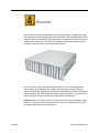
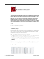
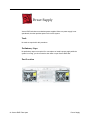
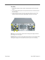
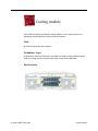
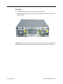
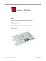
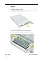
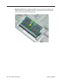
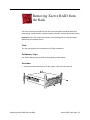
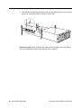
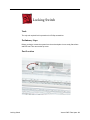
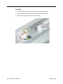
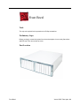
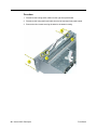
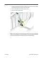
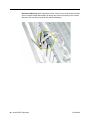
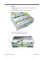
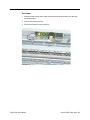
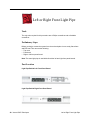
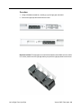
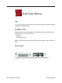
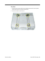
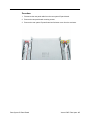
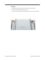
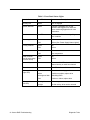
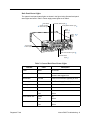
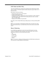
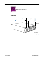
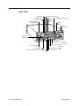
Service Source Xserve RAID 17 March 2003 © 2003 Apple Computer, Inc. All rights reserved. Service Source Basics Xserve RAID © 2003 Apple Computer, Inc. All rights reserved. Overview Xserve RAID is a storage system that provides high-performance, scalable data access and management. It was designed to work with Xserve but is also compatible with desktop computers back to the Power Mac G4 (Digital Audio), as long as the computer has system software OS X (version 10.2.3 or later). A host adapter card must be installed in these computers to allow connection to the Xserve RAID system. Xserve RAID offers dual independent RAID controllers, up to 14 hot-pluggable hard drives, and two hot-pluggable power supplies. Also featured are several connection options, including dual 2-gigabit fibre channel ports, dual Ethernet ports (for managing the system remotely), and dual uninterruptible power supply (UPS) ports. The system is 5.25 inches (3U) high and can be mounted in a rack with four mounting posts. Important: Due to the weight of the unit, two people are necessary for unpacking, lifting, mounting, or replacing the Xserve RAID system in a rack. Do not attempt to lift or move the system without help from another person. Overview Xserve RAID Basics - 1 Features Key features of Xserve RAID include: • 3U enclosure (5.25 inches high) • rack optimized • dual independent RAID controllers, each with a minimum of 128 megabytes (MB) of RAM cache • up to 14 hot-swappable ATA-100 Apple Drive Modules, each with a minimum of 180 gigabyte (GB) capacity • dual hot-swappable power supplies • dual AC power connections • dual hot-swappable cooling modules • dual 2-gigabit (Gb) copper fibre channel ports, supporting point-to-point and fabric (switched) connections • dual Ethernet ports for remote management of the system • dual ports for uninterruptible power supply (UPS) management • Mac OS X compatibility (version 10.2 or later) • Apple Fibre Channel PCI card (sold separately) with dual fibre channel connectors for host system • optional dual battery backup for controller cache • optional service parts kit • optional drive modules Rack Mount Xserve RAID is designed to be mounted in a rack; however, rack mounting is optional. Because of the weight of the system, lifting or transferring Xserve RAID from a rack requires two people. For information on mounting Xserve RAID in a rack, see the Xserve RAID Setup Guide. 2 - Xserve RAID Basics Features Quick-Swap Modules Several modules can be easily replaced in Xserve RAID without removing the system from its rack. Most of these modules are both redundant and hot-swappable. The following table is a quick reference to these modules: Table 1: Quick-Swap Modules Module Hot-swappable? Redundant? ATA Drives Yes Depends on RAID config Power Supplies Yes Yes Cooling modules Yes Yes Battery Modules Yes Yes Controller Modules No: System must be shut down first No: Upper controller manages left seven drives; lower controller manages right seven drives Identifier Light/Button The identifier light on the Xserve RAID front panel turns on when internal sensors or a systems administrator detects a problem with the unit. The light can also be turned on by pressing the identifier button. This indicator will help you locate which Xserve RAID in a rack needs servicing. Note: A duplicate identifier light/button is on the unit’s back panel. Hot-Pluggable ATA Drives Xserve includes fourteen hard drive bays at the front of the server, each of which supports a hot-pluggable ATA/100 drive module available only from Apple. You can replace or install hard drives while the server is running; you do not need to shut down or open the server first. A status light on the front of each drive indicates when it is safe to remove the drive without losing data. For more information, see “Hard Drive” in the Take Apart chapter. RAID Controller Modules Xserve RAID includes two controller modules, each with a minimum of 128 MB RAM. The top controller manages the seven drive modules on the system’s left side (viewed from the front of the system); the bottom controller manages the seven drive modules on the right. Each controller module consists of the controller card, processor, and memory. Features Xserve RAID Basics - 3 Power Supplies Xserve RAID includes two redundant power supplies, each with an AC power connection. When one power supply is not operational, the other provides power for the entire system. You can replace or install a power supply while the system is running. If one power supply is removed from the system, it must be reinstalled or replaced with a working one as soon as possible to prevent the drive modules from overheating. Cooling modules Xserve RAID includes two redundant cooling modules. If one cooling module is not operational, the other provides cooling for the entire system. You can replace or install a cooling module while the system is running. If one cooling module is removed from the system, it must be reinstalled or replaced with a working one as soon as possible to avoid an over-temperature condition, which causes the system to shut down. Backup Batteries Xserve RAID may include up to two optional, redundant backup batteries, which protect data in the controllers’ cache in the event of a power interruption. The Xserve RAID power supplies charge the battery modules when they are installed in the system. The batteries can be replaced or installed while the system is running. To check a battery’s charge when the module is out of the system, press the button on the underside of the module. All four green LEDs light when the battery module is fully charged. You can also use the monitoring or admin software to determine the battery’s charge. See “Remote Monitoring” in the Troubleshooting chapter. For proper operation of the battery, check the status lights on the front of the module. See “Status Lights” in the Troubleshooting chapter. Host Adapter Card The Apple Fibre Channel card is a 7-inch PCI card designed for use with Xserve RAID systems. The card is installed in a host system so that it can connect, using one or two fibre channel cables, to the controller cards in Xserve RAID. The host card provides fibre channel communication in both directions simultaneously at up to 2 gigabits per second (Gb/sec). If the card is used in an Xserve, it must be installed in the top PCI slot of the dual-slot riser card. If host adapter cards are installed in each of two host systems, they can both connect to the same Xserve RAID: one host to the top controller card (for access to the left seven drives) and the other host to the bottom controller card (for access to the right seven drives). 4 - Xserve RAID Basics Features Ports The standard configuration of Xserve RAID includes the following ports on the back panel: two 2-gigabit copper fibre channel ports, two gigabit Ethernet ports, and two ports for uninterruptible power supply (UPS) management. System administrators or service providers can connect a laptop computer or terminal to the Ethernet ports and then use command-line tools to change settings on the server. Note: For a diagram of the ports location, see “Back Panel” in the Views chapter. Diagnostics Two types of diagnostics are available for Xserve RAID: • status lights • remote monitoring For more information, see “Diagnostic Tools” in the Troubleshooting chapter. Features Xserve RAID Basics - 5 Service Source Take Apart Xserve RAID © 2003 Apple Computer, Inc. All rights reserved. General Information Tools No tools are required for removing or installing the following parts: hard drive, power supply, cooling module, controller module, and backup battery. Other parts require only a Phillips screwdriver. If the system is locked, you will also need the Allen wrench key that came with the system. Before Opening Xserve RAID Unlocking Xserve RAID If the system is in the locked position (the yellow security LED on the front panel is on), use the Allen key that came with the system to unlock it. Shutting Down You must shut down the system before replacing or installing all parts except the hard drives, power supplies, cooling modules, and backup batteries. Before shutting down, be sure to alert users that the system will be unavailable for a period of time. Warning: After shutting down the system, you must wait a few minutes before servicing it to allow internal components to cool. Electrostatic Discharge (ESD) Precautions Follow these steps to avoid damage from ESD before working inside Xserve RAID. 1. Shut down the system. 2. Unplug all external cables except the power cords. 3. Touch the Xserve RAID metal case to discharge static electricity. 4. Unplug the power cords. 5. With the help of another person, remove the system from the rack, and place it on a flat surface, preferably covered by an ESD mat. 6. Put on an ESD wrist strap. 7. To avoid static electricity building back up in your body, do not walk around the room until after you have finished working and closed the system. General Information Xserve RAID Take Apart - 1 Hard Drive Module Xserve RAID includes fourteen hard drive bays at the front of the system. Drives come as modules attached to carriers; they are removed from or installed in the system as a unit. Note: Blank drive carriers, which may fill some of the hard drive bays, follow the same take-apart procedure as hard drives. If you are replacing a blank carrier with a drive module, instruct the system’s administrator to keep the blank for possible future use. Blank carriers must be installed in all empty bays to maintain proper airflow through the system. Tools No tools are required for this procedure. Preliminary Steps Before you begin, make sure the drives are in the unlocked position. No other preliminary steps are required. You can replace or install hard drives while Xserve RAID is running; you do not need to shut down or open the unit first. Note: There are two LED indicators on the front of each drive. • The right LED shows drive status: a green light indicates the drive is good; a yellow or red light indicates the drive should be replaced or removed and reinserted. • The left LED shows drive activity: when the light is blinking, the system is reading from or writing to the drive. To avoid losing data, never remove a drive when the lower LED is blinking. WARNING: Drives must be in the unlocked position before you attempt to remove a drive. If the drives are locked, pulling on the drive to remove it could damage the drive handle. Part Location 2 - Xserve RAID Take Apart Hard Drive Module Procedure 1. Make sure the drive being replaced is not in use by any application and that removing it will not disrupt the RAID scheme in use. 2. Press the handle on the front of the drive module so that the handle pops out. 3. Wait for the right LED on the drive to go out. Then grasp the drive handle, and pull the drive module out of the system. Important:To maintain proper airflow, do not leave a drive bay empty. If you permanently remove a drive, replace it with a blank drive module. Hard Drive Module Xserve RAID Take Apart - 3 Power Supply Xserve RAID includes two redundant power supplies. When one power supply is not operational, the other provides power for the entire system. Tools No tools are required for this procedure. Preliminary Steps No preliminary steps are required. You can replace or install a power supply while the system is running; you do not need to shut down or open Xserve RAID first. Part Location 4 - Xserve RAID Take Apart Power Supply Procedure 1. For the power supply you want to replace, unplug the power cord from the power source. 2. Lift the clip that holds the power cord in place and remove the cord from the back of the power supply. 3. Grasp the handle at the top of the power supply and pull down to unlock it. Then holding the handle, pull the power supply straight out the back of the system. Warning: Do not reach inside the system when removing a power supply or when the power supply is out of the system. Important: When you remove a power supply from the system, be sure to replace it with a working power supply as soon as possible to prevent the system from overheating. Power Supply Xserve RAID Take Apart - 5 Cooling module Xserve RAID includes two redundant cooling modules. If one cooling module is not operational, the other provides cooling for the entire system. Tools No tools are required for this procedure. Preliminary Steps No preliminary steps are required. You can replace or install a cooling module while the system is running; you do not need to shut down or open Xserve RAID first. Part Location 6 - Xserve RAID Take Apart Cooling module Procedure 1. Press apart the two latches on the back of the cooling module. 2. Holding the cooling module by the latches, pull it straight out the back of the Xserve RAID enclosure. Important: When you remove a cooling module from the system, be sure to replace it with a working cooling module as soon as possible to prevent the system from overheating. Cooling module Xserve RAID Take Apart - 7 Controller Module Xserve RAID includes two controller modules. The top controller manages the seven drive modules on the system’s left side (viewed from the front of the system); the bottom controller manages the seven drive modules on the right. The controller module consists of the controller card, processor, and memory. This procedure explains how to remove the controller module from the enclosure and how to open the module’s case to access the controller card. Tools No tools are required for this procedure. Preliminary Steps You must shut down the system, using the admin or monitoring software, before removing or installing a controller module. Part Location 8 - Xserve RAID Take Apart Controller Module Procedure 1. Press apart the two latches on the back of the controller module. 2. Holding the controller module by the latches, pull it straight back out of the enclosure. 3. If you are removing the controller card from the case, remove the two screws on the front of the case, and slide out the bottom half of the case. Note: The controller card is attached to the bottom of the controller module case. Do not attempt to separate the card from the bottom case. Replacement Note: If you are replacing the controller card with a new card, you must transfer the processor and memory modules to the replacement card. Controller Module Xserve RAID Take Apart - 9 Processor The processor sits on the controller card inside the controller module case. Tools The only tools required for this procedure are a Phillips screwdriver and needlenose pliers. Preliminary Steps Before you begin, remove the controller module from the enclosure. Part Location 10 - Xserve RAID Take Apart Processor Procedure 1. Remove the two screws on the front of the controller module case. 2. Slide out the bottom half of the case. Note: The controller card is attached to the bottom of the controller module case. Do not attempt to separate the card from the bottom case. 3. Place the controller card on a flat sturdy surface. Using needlenose pliers, compress the two plastic pegs holding the processor in place. Then, holding the processor by the edges, pull it straight up to disconnect it from the controller card. Important: After you replace the processor, be sure to replace the Ethernet label on the controller module with the Ethernet label included with the new processor. Processor Xserve RAID Take Apart - 11 Memory (DIMMs) The memory DIMM sits on the controller card inside the controller module case. Tools The only tool required for this procedure is a Phillips screwdriver. Preliminary Steps Before you begin, remove the controller module from the enclosure. Part Location 12 - Xserve RAID Take Apart Memory (DIMMs) Procedure 1. Remove the two screws on the front of the controller module case. 2. Slide out the bottom half of the case. Note: The controller card is attached to the bottom of the controller module case. Do not attempt to separate the card from the bottom case. 3. Release the two latches that hold the memory DIMM in place. 4. Holding the DIMM by the edges, disconnect it from the controller card. Memory (DIMMs) Xserve RAID Take Apart - 13 Replacement Note: When installing the DIMM, be sure to insert it at an angle into the DIMM connector. Once the DIMM is connected, rotate it down flush with the controller card until you feel the latches snap into place. 14 - Xserve RAID Take Apart Memory (DIMMs) Battery Module Xserve RAID may include up to two optional, redundant backup battery modules, which protect data in the controllers’ cache in the event of a power interruption. The battery module consists of a battery cell, battery recharger board, battery light pipe, and battery cable. This procedure explains how to remove the battery module from the enclosure. Tools No tools are required for this procedure. Preliminary Steps No preliminary steps are required. You can replace or install a battery module while the system is running; you do not need to shut down or open Xserve RAID first. Part Location Battery Module Xserve RAID Take Apart - 15 Procedure 1. Squeeze together the two latches on the back of the battery module, and holding it by the handle, pull it straight back. 2. Remove the battery module from the Xserve RAID enclosure. Note: When first installed, a new battery module will take several hours to charge completely. The system must be turned on to charge the battery. Important:To maintain proper airflow, do not leave a battery bay empty. If you permanently remove a battery module, replace it with a blank battery cover. 16 - Xserve RAID Take Apart Battery Module Removing Xserve RAID from the Rack You must remove Xserve RAID from its rack to access all parts except the hard drive, power supply, cooling module, controller module, processor, memory, and backup battery. Important: Due to the weight of the system, do not attempt to lift or move the system without help from another person. Tools The only tool required for this procedure is a Phillips screwdriver. Preliminary Steps See “Before Opening Xserve RAID” at the beginning of this chapter. Procedure 1. Remove the two screws that secure the system to the front rail of the rack. Removing Xserve RAID from the Rack Xserve RAID Take Apart - 17 2. With one person supporting each side of the unit, slide the system out of the rack and place it on a sturdy, flat surface covered by an ESD mat. Replacement Note: When reinstalling the system, be sure to slide it all the way into the rack until it engages the small posts at the rear of the L-brackets. 18 - Xserve RAID Take Apart Removing Xserve RAID from the Rack Top Cover You must remove the top cover to access all parts except the hard drive, power supply, cooling module, controller module, processor, memory, and backup battery. Tools The only tool required for this procedure is a Phillips screwdriver. Preliminary Steps Before you begin, remove the system from the rack and place it on a sturdy, flat surface and ESD mat. Part Location Top Cover Xserve RAID Take Apart - 19 Procedure 1. Remove the eight mounting screws on each side of the top cover. 2. Slide the top cover a short distance toward the back of the unit. 3. Lift the top cover off the enclosure. 20 - Xserve RAID Take Apart Top Cover Locking Switch Tools The only tool required for this procedure is a Phillips screwdriver. Preliminary Steps Before you begin, remove the system from the rack and place it on a sturdy, flat surface and ESD mat. Then remove the top cover. Part Location Locking Switch Xserve RAID Take Apart - 21 Procedure 1. Disconnect the locking switch cable from the right front panel board. 2. Remove the two screws that mount the locking switch to the chassis. 3. Remove the locking switch from the bottom housing. 22 - Xserve RAID Take Apart Locking Switch Front Bezel Tools The only tool required for this procedure is a Phillips screwdriver. Preliminary Steps Before you begin, remove the system from the rack and place it on a sturdy, flat surface and ESD mat. Then remove the top cover. Part Location Front Bezel Xserve RAID Take Apart - 23 Procedure 1. Disconnect the locking switch cable from the right front panel board. 2. Disconnect the front panel board cable from the left and right front panel boards. 3. Remove the four screws securing the bezel to the bottom housing. 24 - Xserve RAID Take Apart Front Bezel 4. Carefully pull the bezel a short distance straight back off the bottom housing, making sure the bezel clears the barrel of the locking mechanism. 5. Disconnect the cable from the center front panel board. 6. Remove the bezel from the housing. Note: If you are replacing the front bezel with a new bezel, you must transfer the following parts from the original bezel to the replacement bezel: left and right front panel boards and light pipes, front panel buttons, and center front panel board and light pipes. Front Bezel Xserve RAID Take Apart - 25 Replacement Warning: When replacing the bezel, make sure you route the two branches of the front panel board cable straight up through the center front opening in the chassis. Otherwise, the front bezel may pinch the cable and damage it. 26 - Xserve RAID Take Apart Front Bezel Midplane Board Tools The only tool required for this procedure is a Phillips screwdriver. Preliminary Steps Before you begin, remove the system from the rack and place it on a sturdy, flat surface and ESD mat. Then remove the following: • All hard drives • Both power supplies • Both cooling modules • Both controller modules • Both backup batteries, if installed • Top cover • Front bezel Part Location Midplane Board Xserve RAID Take Apart - 27 Procedure 1. Disconnect the front panel board cable and back panel board cables from the midplane board. 2. Grasp the front half of the chassis and rotate 90 degrees up. 3. Remove the six midplane board mounting screws. 4. Remove the midplane from the bottom housing. 28 - Xserve RAID Take Apart Midplane Board Replacement Note: When repositioning the front half of the chassis back into place, make sure the small hole in the center of the chassis fits over the peg in the chassis floor. Midplane Board Xserve RAID Take Apart - 29 Center Front Panel Board Tools The only tool required for this procedure is a Phillips screwdriver. Preliminary Steps Before you begin, remove the system from the rack and place it on a sturdy, flat surface and ESD mat. Then remove the following: • Top cover • Front bezel Part Location 30 - Xserve RAID Take Apart Center Front Panel Board Procedure 1. Remove the two mounting screws on the center front panel board. 2. Remove the board from the bezel. Center Front Panel Board Xserve RAID Take Apart - 31 Center Front Light Pipe Tools The only tools required for this procedure are a Phillips screwdriver and a small flat-blade screwdriver. Preliminary Steps Before you begin, remove the system from the rack and place it on a sturdy, flat surface and ESD mat. Then remove the following: • Top cover • Front bezel • Center front panel board Part Location 32 - Xserve RAID Take Apart Center Front Light Pipe Procedure 1. Using a flat-blade screwdriver, carefully pry up the top center light pipe and shield and remove them from the bezel. 2. Remove the bottom light pipe and shield from the bezel. Center Front Light Pipe Xserve RAID Take Apart - 33 Left Front Panel Board Tools The only tool required for this procedure is a Phillips screwdriver. Preliminary Steps Before you begin, remove the system from the rack and place it on a sturdy, flat surface and ESD mat. Then remove the top cover. Part Location 34 - Xserve RAID Take Apart Left Front Panel Board Procedure 1. Disconnect the front panel board cable from the left front panel board. 2. Remove the mounting screw. 3. Remove the board from the enclosure. Left Front Panel Board Xserve RAID Take Apart - 35 Right Front Panel Board Tools The only tool required for this procedure is a Phillips screwdriver. Preliminary Steps Before you begin, remove the system from the rack and place it on a sturdy, flat surface and ESD mat. Then remove the top cover. Part Location 36 - Xserve RAID Take Apart Right Front Panel Board Procedure 1. Disconnect the locking switch cable and the front panel board cable from the right front panel board. 2. Remove the mounting screw. 3. Remove the board from the enclosure. Right Front Panel Board Xserve RAID Take Apart - 37 Left or Right Front Light Pipe Tools The only tools required for this procedure are a Phillips screwdriver and a flat-blade screwdriver. Preliminary Steps Before you begin, remove the system from the rack and place it on a sturdy, flat surface and ESD mat. Then remove the following: • Top cover • Front bezel • Right or left front panel board Note: The same light pipe is used behind both the left and right front panel boards. Part Location Light Pipe Behind Left Front Panel Board Light Pipe Behind Right Front Panel Board 38 - Xserve RAID Take Apart Left or Right Front Light Pipe Procedure 1. Using a flat-blade screwdriver, carefully pry up the light pipe and shield. 2. Remove the light pipe and shield from the bezel. Replacement Note: The light pipes come with a black plastic shield. Make sure the shield is in correct position over the light pipe before you place the light pipe back into the bezel. Left or Right Front Light Pipe Xserve RAID Take Apart - 39 Front Panel Buttons Tools The only tools required for this procedure are a Phillips screwdriver and either a flat-blade screwdriver or needlenose pliers. Preliminary Steps Before you begin, remove the system from the rack and place it on a sturdy, flat surface and ESD mat. Then remove the following: • Top cover • Front bezel • Left front panel board Note: The front panel button kit comes with both the system identifier button and the mute button. Part Location 40 - Xserve RAID Take Apart Front Panel Buttons Procedure 1. Using needlenose pliers or a flat-blade screwdriver, carefully lift out the button shield from the bezel. 2. Pry up the buttons and remove them from the bezel. Replacement Note: When replacing the buttons, be sure to orient them as illustrated below. Front Panel Buttons Xserve RAID Take Apart - 41 Front Panel Cable Tools The only tool required for this procedure is a Phillips screwdriver. Preliminary Steps Before you begin, remove the system from the rack and place it on a sturdy, flat surface and ESD mat. Then remove the following: • Top cover • Front bezel Part Location 42 - Xserve RAID Take Apart Front Panel Cable Procedure 1. Disconnect the front panel cable from the midplane board. 2. Remove any tape holding the cable to the chassis. 3. Route the cable out through the center opening in the chassis and remove the cable from the enclosure. Front Panel Cable Xserve RAID Take Apart - 43 Rear Panel Cable Tools The only tool required for this procedure is a Phillips screwdriver. Preliminary Steps Before you begin, remove the system from the rack and place it on a sturdy, flat surface and ESD mat. Then remove the top cover. Part Location 44 - Xserve RAID Take Apart Rear Panel Cable Procedure 1. Disconnect the rear panel cable from the midplane board and from the rear power button panel board or rear system ID panel board. 2. Remove the cable from the enclosure. Rear Panel Cable Xserve RAID Take Apart - 45 Rear System ID Panel Board The rear system ID panel board includes the system ID and mute buttons. Tools The only tool required for this procedure is a small Phillips screwdriver. Preliminary Steps Before you begin, remove the system from the rack and place it on a sturdy, flat surface and ESD mat. Then remove the top cover. Part Location 46 - Xserve RAID Take Apart Rear System ID Panel Board Procedure 1. Disconnect the rear panel cable from the rear system ID panel board. 2. Remove the two panel board mounting screws. 3. Remove the rear system ID panel board and its button cover from the enclosure. Rear System ID Panel Board Xserve RAID Take Apart - 47 Rear Power Button Panel Board The rear power button panel board includes the on/off power button and light. Tools The only tool required for this procedure is a small Phillips screwdriver. Preliminary Steps Before you begin, remove the system from the rack and place it on a sturdy, flat surface and ESD mat. Then remove the top cover. Part Location 48 - Xserve RAID Take Apart Rear Power Button Panel Board Procedure 1. Disconnect the rear panel cable from the rear power button panel board. 2. Remove the two panel board mounting screws. 3. Remove the rear power button panel board and its button cover from the enclosure. Rear Power Button Panel Board Xserve RAID Take Apart - 49 Service Source Troubleshooting Xserve RAID © 2003 Apple Computer, Inc. All rights reserved. Diagnostic Tools Xserve RAID includes built-in sensors that detect and report on hard drives, internal temperature, cooling module status or failure, and power status or failure. You can monitor the system’s operation via these sensors and two diagnostic tools: indicator lights on the front and back of the system and remote monitoring software. Status Lights Status lights are located on the front and back panels of Xserve RAID. In addition, there are status lights on the host adapter card. Front Panel Status Lights The system’s front panel status lights are shown in the figure and table below. Mute Button System Identifier Button and Light Drive Module Lock and Status Light Power Supply Status Light Cooling System Status Light Temperature Status Light Controller Status Light Host Activity Lights Drive Module Activity and Status Lights Fibre Channel Link Lights Diagnostic Tools Xserve RAID Troubleshooting - 1 Table 1: Front Panel Status Lights Indicator LED Color Description Security lock Yellow Lock is engaged System identifier Yellow Indicates a hardware error or that someone has toggled it on; check the server monitoring application for more information Mute button No LED Press to turn off the alarm signalling an error condition Power supplies Green OK Red Failure (See “Power Supply Status Lights”) Green OK Red Failure Green OK Red Over temperature RAID controller (one for each group of seven drives) Green OK Red Failure Host activity Blue Two rows of 23 LEDs show level of fibre channel activity on each host channel Fibre channel link Green Two LEDs indicate a link is established Drive module (right LED) Green Powered and running; good Yellow Prefailure condition; replace drive Yellow/green flash Rebuilding RAID Red Problem or failure; replace drive Blinking blue Disk activity; do not remove drive No light No disk activity; drive can be removed Cooling modules Temperature Drive module (left LED) 2 - Xserve RAID Troubleshooting Diagnostic Tools Back Panel Status Lights The system’s back panel status lights are shown in the figure below. General back panel status lights are listed in Table 3. Power supply status lights are in Table 4. Mute Button Controller Status Light System Identifier Button and Light Cooling Module Status Light Power Button and Light Battery Status Lights Power Supply Status Lights Fibre Channel Status Lights Ethernet Status Lights Table 2: General Back Panel Status Lights Indicator Color Power White On and OK System identifier Yellow Indicates a hardware error or that someone has toggled it on Mute button No LED Press to turn off alarm signalling an error Power supplies See “Power Supply Status Lights” Cooling modules Green OK Controllers Green OK Ethernet link Green OK Red Failure Green OK Red Failure Green Charged and OK Red Failure Fibre channel link Batteries Diagnostic Tools Description Xserve RAID Troubleshooting - 3 Table 3: Power Supply Status Lights Power Supply Conditions Green LED Yellow LED Red LED No AC power to either power supply Off Off Off Power supply failure or no AC power to this power supply Off Off On AC power present; standby ouputs on Blinking Off Off Power supply DC outputs on and OK On Off Off Current limit On Off Blinking Predictive failure On Blinking/on Off Host Adapter Card Status Lights The host adapter card’s status lights are shown in the figure and table below. Status Lights SFP Ports Table 4: Host Adapter Card Status Lights LED Color/Status Description No light Link established Blinking green Activity on the channel Yellow No link or there is an error condition 4 - Xserve RAID Troubleshooting Diagnostic Tools RAID Admin and Disk Utility There are two applications for configuring and monitoring Xserve RAID systems: RAID Admin, included on a CD with the system, and Disk Utility, which is part of Mac OS X or Mac OS X Server. RAID Admin is used for the following: • Monitoring the status of one or more systems • Creating or deleting RAID arrays • Adjusting system settings, including system name and password, network address for each RAID controller, fibre channel communication speed, drive cache, controller cache, and LUN masking • Setting up email notification for system alerts Disk Utility is used to modify RAID arrays by adding striping or mirroring to existing RAID arrays. Note: For more information on RAID Admin and Disk Utility, see the document “Using RAID Admin and Disk Utility” on the RAID Admin CD that comes with the Xserve RAID system. Remote Monitoring Use the RAID Admin application to monitor the Xserve RAID system from a host computer. The application allows monitoring in the following areas, each of which is represented by a tab at the top of the RAID Admin window: • Info • Components • Drive & Arrays • Fibre Channel • Network Note: For information on adding and deleting systems to the RAID Admin monitoring list, see the document “Using RAID Admin and Disk Utility.” Diagnostic Tools Xserve RAID Troubleshooting - 5 Info Info reports system name, lock status, controller details, and whether there is a problem or power failure. Components Components shows the operating information about the power supplies, RAID controllers, cooling modules, and cache backup batteries. Clicking the button for a component displays its details. 6 - Xserve RAID Troubleshooting Diagnostic Tools Drive & Arrays Drives & Arrays shows details of each array, the drives in use, and the drives available. Choosing an array from the Array menu displays its details. Fibre Channel Fibre Channel shows information about each RAID controller and the type of fibre channel connection in use. Network Network displays the IP address and related network details for each RAID controller. Diagnostic Tools Xserve RAID Troubleshooting - 7 Block Diagram Midplane ATA 100 ATA 100 Control 10/100 Enet Serial ATA 100 EMU 2 ATA 100 RAID Controller 2 2Gb FC ATA 100 (7) ATA 100 Battery V Charge Off Battery 2 Drive Module 14 Power Control ATA 100 Drive Module 13 Drive Module 12 Drive Module 11 Front Button Board Host Activity Display 5V 12V 3.3V 5V sb Power Supply 2 Drive Module 10 Drive Module 9 5V, Fantac Blowers 1&2 Fan Control ATA 100 Drive Module 8 12C EMU 2 5V 12V 3.3V 5V sb Power Supply 1 Power Control ATA 100 ATA 100 10/100 Enet Serial Control ATA 100 EMU 1 ATA 100 2Gb FC RAID Controller 1 Battery 1 Rear Button Board 8 - Xserve RAID Troubleshooting ATA 100 (7) ATA 100 Battery V Charge Off ATA 100 ATA 100 Drive Module 7 Drive Module 6 Drive Module 5 Drive Module 4 Drive Module 3 Drive Module 2 Drive Module 1 Block Diagram Light Show (2 x 25 LEDs) 12C EMU 1 Service Source Views Xserve RAID © 2003 Apple Computer, Inc. All rights reserved. External Views Front Panel Mute Button System Identifier Button and Light Drive Module Lock and Status Llight Power Supply Status Light Cooling System Status Light Temperature Status Light Controller Status Light Host Activity Lights Drive Module Activity and Status Lights Drive Modules Fibre Channel Link Lights External Views Xserve RAID Views - 1 Back Panel Mute Button System Identifier Button and Light Optional Battery Module Bay (2) Controller Status Light RAID Controller Reset Button Cooling Module Status Light Power Button and Light Battery Status Lights Power Supply Status Lights Fibre Channel Port and Status Light (2) Power Supply (2) Power Socket (2) RAID Controller Module and Status Light (2) 2 - Xserve RAID Views Ethernet Port and Status Light (2) UPS Interface Port (2) Cooling Module (2) External Views