1
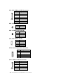
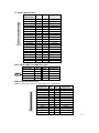
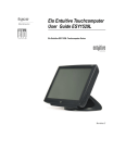
Elo Entuitive Touchcomputer
User Guide
15" LCD Desktop Touchcomputer
ESY1525L/ESY1527L Touchcomputer Series
Revision E
P/N 008594
Elo TouchSystems, Inc.
1-800-ELOTOUCH
www.elotouch.com
Copyright © 2005 Elo TouchSystems Inc. All Rights Reserved.
No part of this publication may be reproduced, transmitted, transcribed, stored in a retrieval system,
or translated into any language or computer language, in any form or by any means, including, but not
limited to, electronic, magnetic, optical, chemical, manual, or otherwise without prior written
permission of Elo TouchSystems.
Disclaimer
The information in this document is subject to change without notice. Elo TouchSystems makes no
representations or warranties with respect to the contents hereof, and specifically disclaims any
implied warranties of merchantability or fitness for a particular purpose. Elo TouchSystems reserves
the right to revise this publication and to make changes from time to time in the content hereof
without obligation of Elo TouchSystems to notify any person of such revisions or changes.
Trademark Acknowledgments
IntelliTouch, SecureTouch, AccuTouch, Entuitive, and MonitorMouse are trademarks of Elo
TouchSystems, Inc.
Other product names mentioned herein may be trademarks or registered trademarks of their
respective companies. Elo TouchSystems claims no interest in trademarks other than its own.
iii
Table of Contents
Chapter 1
Introduction
Chapter 3
Safety/Servicing the Touchcomputer
1
Precautions . . . . . . . . . . . . . . . . . . . . 1
About the Product . . . . . . . . . . . . . . . . . 1
Operating System . . . . . . . . . . . . . . . 2
Windows XP Pro and 2000 Pro . . . . . . . 2
Windows CE .Net Ver4.2 . . . . . . . . . . 2
Customer Display . . . . . . . . . . . . . . . 2
Magnetic Stripe Reader (MSR) . . . . . . . 2
Touchscreen . . . . . . . . . . . . . . . . 2
Drivers . . . . . . . . . . . . . . . . . . . 2
External Connections and Upgrades . . . . 3
External Connections . . . . . . . . . . . . . 3
Wireless Network Capabilities . . . . . . . 3
CD/DVD Drives . . . . . . . . . . . . . . . 3
Wired Network Connections . . . . . . . . 3
Hard Drive for CE.Net Ver4.2 . . . . . . . 3
Mouse . . . . . . . . . . . . . . . . . . . . 3
Keyboard . . . . . . . . . . . . . . . . . . 4
Upgrades and Changes . . . . . . . . . . . . 4
Accessory Kit. . . . . . . . . . . . . . . . . . 4
Models . . . . . . . . . . . . . . . . . . . . . 6
Chapter 4
Chapter 2
Touchcomputer Setup
13
9
Technical Description
15
Block Diagram . . . . . . . . . . . . . . . . .
Computer Specifications . . . . . . . . . . . .
Processor . . . . . . . . . . . . . . . . . .
Memory . . . . . . . . . . . . . . . . . . .
Green Function . . . . . . . . . . . . . . .
Audio Function . . . . . . . . . . . . . . . .
Operating System . . . . . . . . . . . . . .
Ports . . . . . . . . . . . . . . . . . . . . .
Real Time Clock . . . . . . . . . . . . . . .
Windows CE.Net Ver4.2 Board Support Package
Panel Connectors . . . . . . . . . . . . . .
Display . . . . . . . . . . . . . . . . . . . . .
Touchscreen Assembly . . . . . . . . . . . . .
External 12 VDC Power Supply. . . . . . . . .
Stand . . . . . . . . . . . . . . . . . . . . . .
Customer Display . . . . . . . . . . . . . . . .
Optical Parameters . . . . . . . . . . . . .
USB MSR . . . . . . . . . . . . . . . . . . . .
Specifications . . . . . . . . . . . . . . . .
15
22
22
22
22
22
22
22
23
23
23
24
25
25
25
26
26
26
27
Chapter 5
Initial Turn On and Software Registration . . . . . 9
Touchcomputer Operating System Setup . . . 9
License Agreement . . . . . . . . . . . . . 9
Product Key . . . . . . . . . . . . . . . . . 9
Network Settings . . . . . . . . . . . . . . 9
Performing Final Tasks . . . . . . . . . . . 9
Computer Reboots . . . . . . . . . . . . 10
Testing Pre-installed Devices . . . . . . . 10
Customer Display Testing . . . . . . . . . 10
Keyboard Card Reader Testing . . . . . . 10
USB Card Reader Testing . . . . . . . . 10
Controls . . . . . . . . . . . . . . . . . . . 10
Power. . . . . . . . . . . . . . . . . . . . . 11
Power and OSD Lock Out . . . . . . . . . . 12
Technical Assistance . . . . . . . . . . . . . 12
Using the Touchcomputer. . . . . . . . . 12
Using the Web . . . . . . . . . . . . . . 12
Using the Phone . . . . . . . . . . . . . 12
Touchcomputer Component Layout
29
Touchcomputer Assembly . . . . . . . . . . 30
Touchcomputer Exploded View . . . . . . . . 31
Chapter 6
33
Components
External 12 VDC Power Supply. . . . .
Memory and Hard Drive Options . . . .
Windows 2000 Pro and Windows XP
Windows CE.Net Ver4.2 . . . . . .
Cables . . . . . . . . . . . . . . . . .
External Cables . . . . . . . . . . .
Chapter 7
Environmental Requirements
. . .
. . .
Pro .
. . .
. . .
. . .
.
.
.
.
.
.
33
33
33
33
34
34
35
Temperature Ranges . . . . . . . . . . . . . . 35
Humidity. . . . . . . . . . . . . . . . . . . . . 35
1
Altitude . . . . . . . . . . . . . . . . . . . . . 35
Warranty
37
Index
39
2
C
H A P T E R
INTRODUCTION
CHAPTER1
Congratulations on your purchase of an Elo TouchSystems Entuitive
Touchcomputer. This manual is to help you operate and maintain the
Touchcomputer.
Precautions
Follow all warnings, precautions and maintenance as recommended in this
user’s manual to maximize the life of your unit. See Appendix B for more
information on touchmonitor safety.
About the Product
Your LCD Desktop Touchcomputer is a 15" XGA TFT color display with the
following features:
The Touchcomputer consists of a 15 inch LCD monitor and a computer in a
package approximately the size of a monitor. The Touchcomputer is capable of
running Windows CE.Net Ver4.2, Windows 2000 Pro and Windows XP Pro
depending on how the Touchcomputer is configured and the options the user
selects. The Touchcomputer consists of an LCD main display with a touchscreen,
a backlight inverter, a touch controller, speakers, and a mother board. The
Touchcomputer also includes an external 12 VDC power Supply, a stand, a
chassis and case, and internal and external cables. The Touchcomputer provides
an optional Magnetic Stripe Reader and an optional Customer Display. The
Touchcomputer does not come with a keyboard or a Mouse, but it does provide
external ports to add them. The Touchcomputer has on screen touch to use as a
1-1
mouse and an on screen keyboard to take the place of an external keyboard. The
Touchcomputer provides the following options.
Operating System
A selection of operating systems can be made between Windows CE.Net Ver4.2,
Windows XP Pro or Windows 2000 Pro.
Windows XP Pro and 2000 Pro
When Windows XP Pro and Windows 2000 Pro are selected, the Touchcomputer
will have a 20 GB or greater hard drive and 256 MB of SDRAM. The
Touchcomputer will boot from the hard drive, which contains the operating
system. No compact Flash will be provided.
Windows CE.Net Ver4.2
When Windows CE.Net Ver4.2 is selected as the operating system, the
Touchcomputer will boot from the onboard 64MB of compact flash. The
Touchcomputer will include 256MB of SDRAM. No hard drive will be provided.
Customer Display
An optional serial customer display can be selected. No applications software is
provided for the Customer Display. A test program is provided to verify the
Customer Display is operating properly.
Magnetic Stripe Reader (MSR)
A USB HID (not available in Windows CE.Net Ver4.2) or USB Keyboard
Emulation MSR can be selected. No applications software is provided for the
MSR. A test program is provided to verify the MSR is operating properly.
Touchscreen
AccuTouch or IntelliTouch touchscreens may be selected with a USB interface.
No applications software is provided for the touchscreen. A test program is
provided to verify the touchscreen is operating properly.
Drivers
Drivers and test programs will be provided with each system to operate all
options selected.
1-2
Elo Entuitive Touchmonitor User Guide
External Connections and Upgrades
The following drawing shows the Touchcomputer External connector panel. This
panel of connectors is used by the user to make external connections to the
Touchcomputer. No external connections, other than power, are needed for the
Touchcomputer to operate.
External Connections
Using these external connections, the following capabilities can be provided to
the Touchcomputer by the user:
Wireless Network Capabilities
Wireless network capabilities can be provided via a wireless card added to the
PCMCIA slot.
CD/DVD Drives
CD/DVD drives can be added using the external USB inputs.
Wired Network Connections
Wired network connections including internet can be made using the Ethernet
input.
Hard Drive for CE Version
A hard drive for the CE version of the Touchcomputer can be added using the
USB inputs or HD can be added internally.
Mouse
A mouse can be added using the mouse port.
1-3
Keyboard
• A keyboard can be added using the keyboard port.
Upgrades and Changes
A laptop type hard drive (2.5") can be added internally to the CE version of the
Touchcomputer.
• SDRAM can be increased from the standard 256 M to 512 M
• Compact Flash can be added (through the compact flash door in the back
of the Touchcomputer) to the Touchcomputer on Windows XP Pro and
Windows 2000 Pro Touchcomputers.
• Customer Displays and Magnetic Stripe Readers can added to any
Touchcomputer.
• Operating System changes between Windows XP Pro and Windows 2000 Pro
can be made by loading the proper operating system on the internal hard drive.
• Operating system changes between either Windows 2000 Pro and Windows
XP Pro to Windows CE.Net Ver4.2 can be made by adding Compact Flash
with the appropriate image and booting from the compact flash.
• Operating system changes from Windows CE.Net Ver4.2 to either Windows
XP Pro or Windows 2000 Pro can be made by adding an internal or external
hard drive with the new operating system loaded.
Accessory Kit
An accessory kit will be provided with each monitor. The accessory kit provides
the following:
• Touch Tool CD-The touchtool CD contains the drivers and manual for
EloTouch touchscreen products. The touch drivers will come loaded with the
Touchcomputer. These drivers are provided if the operating system needs to
be reloaded.
• Touchcomputer CD-The Touchcomputer CD contains the drivers for devices
used with the Touchcomputer, a copy of the Touchcomputer Users Guide,
test programs to test the Touchcomputer, a copy of the My-T-Touch software,
a copy of the Windows CE.Net Ver4.2 image. These are only needed if the
operating system needs to be reloaded. A Board support Package (BSP) for
Windows CE.Net Ver4.2 is included for creating customers own image. See
the BSP notes and directions on the CD. See section 4.2.8 for a description
of the BSP.
• Quick Install Guide-Shows pictorially how to operate the Touchcomputer.
1-4
Elo Entuitive Touchmonitor User Guide
• US Power Cable
• European Power Cable
• Power Brick
• Applicable Operating System CD
• Windows 2000 Pro
• Windows XP Pro
• No CD is provided for Windows CE.Net Ver4.2 (but the image is on the
Touchcomputer CD.)
• No serial or USB cables are provided
1-5
Models
The Touchcomputer is available in the following models. A key at the end of the model list
explains the options.
E08919-000
F00839-000
C63175-000
E73369-000
E36798-000
A78783-000
E71602-000
ESY1525L-7UWA-1-CE
ESY1525L-7UWA-1-CE-C1
ESY1525L-8UWA-1-CE
ESY1525L-8UWA-1-CE-M3
ESY1525L-8UWA-1-CE-C1
ESY1525L-8UWA-1-CE-M3C1
ESY1527L-8UJA-1-CE
C32392-000
A82367-000
D37281-000
D58125-000
D61906-000
C94408-000
E21843-000
F41051-000
ESY1525L-7UWA-1-XP
ESY1525L-7UWA-1-XP-C1
ESY1525L-8UWA-1-XP
ESY1525L-8UWA-1-XP-M2
ESY1525L-8UWA-1-XP-M3
ESY1525L-8UWA-1-XP-M2C1
ESY1525L-8UWA-1-XP-M3C1
ESY1527L-8UJA-1-XP
F95046-000
A88088-000
ESY1525L-7UWA-1-2K
ESY1525L-7UWA-1-2K-C1
C04515-000
ESY1525L-8UWA-1-2K
F84197-000
C48832-000
A84590-000
F83851-000
ESY1525L-8UWA-1-2K-M2
ESY1525L-8UWA-1-2K-M3
ESY1525L-8UWA-1-2K-M2C1
ESY1525L-8UWA-1-2K-M3C1
1-6 Elo En tu iti v e To u c h mo n ito r U s er G u id e
Key
PIP Description Key
ESY = Elo System
15 = 15 Inch Display
25 = Desktop cabinetry (In grey plastics only)
L = LCD
7 = AccuTouch
8 = IntelliTouch
S = Serial controller
U = USB controller
W = Worldwide agencies
A = Revision number
1 = Antiglare glass
Mx = MSR unit
x = 2 = MSR USB HID
x = 3 = MSR USB Keyboard Emulation
Cx = Customer Display
x = 1 = Serial Customer Display
CE = Windows CE.Net 4.2 Pro+
Xp = Windows Xp Pro
2K = Windows 2000 Pro
1-7
1-8
Elo Entuitive Touchmonitor User Guide
C
H A P T E R
Touchcomputer SETUP
CHAPTER2
Initial Turn On and Software Registration
Touchcomputer Operating System Setup
The initial setup of the Windows operating system takes approximately 5-10
minutes. Additional time may be needed depending on computers hardware
configuration and connected devices. To setup the Windows OS for you
computer, turn on your computer and follow the instructions on the screen. The
Touchcomputer should be connected to a network providing an internet
connection. It is possible to register Windows over the telephone.
License Agreement
• Click “I accept this agreement”
• Click “Next”
Product Key
• Type in the 25 character product code located on the back of the unit.
• Click “Next”
Network Settings
• Wait for windows to configure network settings.
Performing Final Tasks
• Wait for windows to configure network settings.
2-9
Computer Reboots
• Wait for computer to reboot and finally boot up to the desktop.
Testing Pre-installed Devices
Touchcomputer come pre installed with several different hardware options. To
test these options, click on the following icons on the Windows toolbar on the
bottom right of the computer. You may also use the desktop icons.
Customer Display Testing
• Click on the “CD” icon.
• The customer display should change, now displaying the text “Elo
TouchSystems Customer Display”.
Keyboard Card Reader Testing
• Click on the “KCR” icon.
• Click on scan button
• Scan a credit card ensure data scanned correctly by seeing applicable
information on all three tracks from the credit card.
USB Card Reader Testing
• Click on the “UCR” icon
• Click on scan button
• Scan a credit card ensure data scanned correctly by seeing applicable
information on all three tracks from the credit card.
Controls
There are two controls to operate the Touchcomputer. There is a brightness
control and a volume control. To increase the brightness, press switch 3. To
decrease brightness, press switch 4. To increase the volume, press switch 1.
To decrease volume, press switch 2.
2-10
Elo Entuitive Touchmonitor User Guide
Touchcomputer Controls
Switch 1
Switch 2
Switch 3
Switch 4
Switch 5
Power
To turn power off, press and hold switch 5. To turn on press and hold switch 5
then shut down. To do a hard shutdown, press and hold switch 5. To turn power
on, press the power button once.
2-11
Power and OSD Lock Out
Normally the 5 switches on the side of the monitor depicted in the figure in the
controls section control power, brightness and volume. The power switch can be
made not to operate by activating the power lockout function. The brightness
and volume adjustment can be made not to operate by activing the OSD lockout
function. The OSD lockout function can be a activate by simultaneously
pressing Switch 1 and Switch 2. The power lockout function can be activated
by simultaneously pressing Switch 1 and Switch 3. When the switches are
pressed, OSD lock or power lock will appear. The power lockout state can be
set by releasing Switch 1 and Switch 3 in the desired state of power lock or
power unlock.
The OSD lockout state can be set by releasing Switch 1 and 2 in the desired
state of OSD lock or OSD unlock.
Technical Assistance
There are three methods to obtain contact information for technical assistance
on the Touchcomputer.
• Touchcomputer itself
• the Web
• telephone
These methods are described below.
Using the Touchcomputer
You can access the support information by going to the System Properties and
clicking on the “Support Information” button. You can get to get to System
Properties by either of the following methods:
• Right click “My Computer” and choose “Properties”
• Click on the “Start Button” and select “control panel”and double click on the
“System” icon.
Using the Web
www.elotouch.com/support/default.asp
Using the Phone
Call toll-free 1-800-557-1458
2-12
Elo Entuitive Touchmonitor User Guide
C
H A P T E R
SAFETY/SERVICING THE Touchcomputer
CHAPTER3
When servicing the computer perform the following:
• Perform an orderly shutdown using the operating system menu.
• Shut down the Touchcomputer and remove all external cables.
• When opening the Touchcomputer, periodically touch any metal parts of the
Touchcomputer, such as metal portions of the case or connector shells on the
monitor.
• Handle components and cards with care. Do not touch components on the
cards. When adding memory, hold it by the edges, not contacts.
3-13
3-14
Elo Entuitive Touchmonitor User Guide
C
H A P T E R
TECHNICAL DESCRIPTION
CHAPTER4
Block Diagram
The block diagram of the Touchcomputer is shown below:
Elo Touchcomputer Block Diagram
CN7
Speakers
LCD
Inveter
J11
+12
VDC
Dual USB
Port(500 ma)
USB2
Dual USB
Port(500 ma)
CN13
Serial Port
CN14
Serial Port
J16
OSD
Switch
panel
CN10
USB1
Optional
Hard Drive
CN11
J7
Optional
Compact Flash
J17
PS2
keyboard
PS2
keyboard
J12
PCMCIA
J15
Ethemet
Port
CN5
Mother board
CN1
CN9
Serial
Port
USB
Port
Optional
MSR
CN3
Internal
+5 VDC
@1 amp
CN2
Internal
Serial
Port
Optional
Customer
Display
Optional
AccuTouch or
IntelliTouch
Touchscreen
CN4
CN6
+5/+12vdc
USB
Port
Optional AccuTouch
or IntelliTouch USB
Controller
4-15
Mother Board Block Diagram
MEMORY
PC133/SDR
VIA EDEN
ESP 600 MHZ
PROCESSOR
FSB
BOOT ROM
VIA VT8606 TWISTER
NORTHBRIDGE
GRAPHICS CORE AND
MEMORY CONTROLLER
REALTEK
RTL8100C FAST
ETHERNET
CONTROLLER
PCI
VIA VT82C686B
SOUTHBRIDGE
PERIPHERAL
CONTROLLER
FAST
ETHERNET
SOUND
KEYBOARD
MOUSE
HARD DRIVE
2 SERIAL PORTS
4 USB PORTS
LCD
DISPLAY
4-16
Elo Entuitive Touchmonitor User Guide
WINDBOND
W83977F
I/O
CONTROLLER
2 SERIAL PORTS
TI PCI1410
PC CARD
CONTROLLER
PCMCIA
Connectors on Mother Board
The connectors on mother board allows you to connect external devices such as keyboard, floppy disk
drives, hard disk drives, printers, etc. The following table lists the connectors on mother board and their
respective functions.
Connector Locations on Mother Board
Connectors on Mother Board
CN1, CN2: COM4 and COM3 Connectors
CN3: +5V Connector
CN4: +5V AND +12V Connector
CN6, CN9: USB Pin Header
CN10: Panel Inverter Power Connector
CN11: OSD Panel Board Connector
CN13, CN147: COM1 and COM2 Serial Ports
FDD1: Floppy Drive Connector
USB1, USB2: USB Connectors
J4: IrDA Connector
J6: Reset Button and IDE LED
J7: Primary IDE Connectors
J9: System Fan Power Connector
J11: 24-bit LVDS Connector (DF13-20)
J13: VGA CRT Connector
J14: System Fan Power Connector
J16: PS/2 Keyboard Connector
J17: PS/2 Mouse Connector
4-17
CN1, CN2: COM4 and COM3 Connectors
Pin #
Signal Name
1
DCD
2
RXD
3
CTS
4
GND
5
TXD
6
RTS
7
DSR
8
DTR
CN3: +5V Connector
Pin # Signal Name
1
+5V
2
Ground
CN4: +5V AND +12V Connector
Pin # Signal Name
1
+5V
2
Ground
3
+12V
CN6, CN9: USB Pin Header
Pin # Signal Name
1
Ground
2
USB3
USB+
4
Vcc
CN10: Panel Inverter Power Connector
Pin #
1
2
3
4
5
Signal Name
+12V
Ground
Bright Adj
Ground
BKLT ON
CN11: OSD Panel Board Connector
Pin #
Signal Name
1
Vol+
2
Vol3
Bright+
4
Bright5
Ground
6
Power On/Off
4-18
Elo Entuitive Touchmonitor User Guide
J7: Primary IDE Connectors
Pin #
Pin #
Signal Name
1
3
5
7
9
11
13
15
17
19
21
23
25
27
29
31
33
35
37
39
41
43
2
4
6
8
10
12
14
16
18
20
22
24
26
28
30
32
34
36
38
40
42
44
Ground
Host data 8
Host data 9
Host data 10
Host data 11
Host data 12
Host data 13
Host data 14
Host data 15
Key
Ground
Ground
Ground
Host ALE
Ground
No connect
No connect
ASDRAMess 2
Chip select 1
Ground
Vcc
N.C.
Signal Name
Reset IDE
Host data 7
Host data 6
Host data 5
Host data 4
Host data 3
Host data 2
Host data 1
Host data 0
Ground
DRQ0
Host IOW
Host IOR
IOCHRDY
DACK0
IRQ14
ASDRAMess 1
ASDRAMess 0
Chip select 0
Activity
Vcc
Ground
CN13, CN147: COM1 and COM2 Serial Ports
Signal Name
DCD
RXD
TXD
DTR
GND
Pin #
1
2
3
4
5
Pin #
6
7
8
9
10
Signal Name
DSR
RTS
CTS
RI
NC
FDD1: Floppy Drive Connector
FDD1is a slim 26-pin connector and will support up to 2.88MB FDD.
Signal Name
Pin #
Pin #
Signal Name
VCC
VCC
VCC
NC
NC
DINST
NC
GND
GND
GND
NC
GND
GND
1
3
5
7
9
11
13
15
17
19
21
23
25
2
4
6
8
10
12
14
16
18
20
22
24
26
INDEX
DRV_SEL
DSK_CH
NC
MOTOR
DIR
STEP
WDATA
WGATE
TRACK
WPROT
RDATA
SIDE
4-19
USB1, USB2: USB Connectors
Pin #
Signal Name
1
Vcc
2
USB3
USB+
4
Ground
J9: System Fan Power Connector
J9 is a 3-pin header for an optional fan. The fan must be a 12V fan.
Pin #
Signal Name
1
Ground
2
+12V
3
Rotation detection
J11: 24-bit LVDS Connector (DF13-20)
Signal Name
TX0Ground
TX15V/3.3V
TX3TX2Ground
TXC5V/3.3V
+12V
Pin #
2
4
6
8
10
12
14
16
18
20
Pin #
1
3
5
7
9
11
13
15
17
19
Signal Name
TX0+
Ground
TX1+
Ground
TX3+
TX2+
Ground
TXC+
ENABKL
+12V
J13: VGA CRT Connector
J13 is an 8-pin header for an optional external VGA CRT female connector.
Signal Name
Red
Green
Blue
N.C.
Ground
Ground
Ground
Ground
Pin
1
3
5
7
9
11
13
15
Pin
2
4
6
8
10
12
14
16
Signal Name
Vcc
Ground
N.C.
N.C.
H-Sync
V-Sync
N.C.
N.C.
J14: System Fan Power Connector
J14 is a 3-pin header for the optional system fan. The fan must be a 12V fan.
Pin #
Signal Name
1
Ground
2
+12V
3
Rotation detection
4-20
Elo Entuitive Touchmonitor User Guide
J16: PS/2 Keyboard Connector
6
5
4
3
1
2
Pin
1
2
3
4
5
6
Signal Name
Keyboard data
N.C.
GND
5V
Keyboard clock
N.C.
J17: PS/2 Mouse Connector
Pin
Signal Name
6
5
1
Mouse data
2
N.C.
4
3
3
GND
2
1
4
5V
5
Mouse clock
6
N.C.
4-21
Computer Specifications
Processor
• VIA Eden 600MHz low power CPU or equivalent
Memory
• RAM- 256 MB expandable to 512 MB
Green Function
• APM 1.2 compliant
Audio Function
• Stereo one watt capability per channel
Operating System
• Support for WinCE.Net Ver4.2
• Support for Windows 2000 Pro
• Support for Windows Xp Pro
Ports
• Four RS-232 Serial Ports. Two internal ports(CN2 and CN1) and 2 external
ports (CN13 and CN14).
• Connectors-External ports shall use standard DB9 connectors.
• Six USB self powered version 1.1 Ports. All ports have the capability to
provide 0.5 amps at 5 VDC each. Two ports are internal (CN6 and CN9) and
four external (USB1 and USB2).
• The external USB ports shall use two standard dual USB connectors.
• One Ethernet 100/10Base-T Port (J15)
• One PCMCIA version 2.1 Slot (J12)
• PS2 Keyboard (J16)
• PS2 Mouse (J17)
4-22
Elo Entuitive Touchmonitor User Guide
• One Compact Flash Socket (CN5)
• One hard drive socket located on the bottom of the board (J7)
Real Time Clock
• Battery backed up real time clock that features a multi-century calendar.
• Lithium battery with socket.
• On Screen Display
• Volume Control
• Backlight Brightness
Windows CE.Net Ver4.2 Board Support Package
A board support package is available to assist users with custom software
development. The board support package contains the following items:
• Installation instructions
• A platform image that can be added to the Wince platform directory.
• A .cec file or equivalent to add the platform features to the platform builder
catalog.
• A boot loader to support Ethernet debug and download.
• All testing shall be done with the final image from Elo.
Panel Connectors
The following connectors are available from the outside of the Touchcomputer
• Four USB ports
• Ethernet
• 2 serial port
• PS2 Keyboard (No keyboard provided)
• PS2 Mouse (No mouse provided)
• Board input Power
• PCMCIA Slot with eject button
• Compact Flash
4-23
Display
The LCD display consists of an LCD, inverter, and OSD switch module. The
performance of the LCD display will be:
Display Size
Native Resolution
Display Color
Number
Display Type
Typical Contrast
Ratio
Typical/Min
Brightness
Typical Display
Speed
Typical Vertical
Viewing Angle
Typical Horizontal
Viewing Angle
Chromaticity
4-24
15.0 diagonal
1024 x 768 pixels
16.2 million Colors, 6 Bit+FRC
a-Si TFT active – matrix
500:1
LCD
350 cd/m²
AccuTouch287 cd/m²
IntelliTouch322 cd/m²
Rising Time 9 ms / Falling Time16 ms
60 deg (looking down) / 45 deg (looking
up) @CR 10
70 deg (looking down) / 55 deg (looking
up) @CR 5
60 deg (looking from Left) / 60 deg (Looking from Right)CR 10
75 deg (looking down) / 75 deg (looking
up) @CR 5
Chromaticity coordinates will fall within
the values in the table
Elo Entuitive Touchmonitor User Guide
TABLE 1. Chromaticity
Symbol
Chromaticity of
White
Chromaticity of
Red
Chromaticity of
Green
Chromaticity of
Blue
Wx
Wy
Rx
Ry
Gx
Gy
Bx
By
Values
Minimum
0.282
0.288
0.613
0.314
0.274
0.536
0.111
0.055
Typical
0.312
0.318
0.6437
0.344
0.304
0.566
0.141
0.085
Maximum
0.342
0.348
0.673
0.374
0.334
0.596
0.171
0.115
Touchscreen Assembly
The touchscreen assembly consists of a touchscreen and a controller.
AccuTouch or IntelliTouch touchscreens will be provided as options and use
one of the USB ports on the mother board .
External 12 VDC Power Supply
The Touchcomputer shall be powered by 12 VDC from a universal type power
supply brick with the following characteristics:
• Input voltage 85 to 263 vac
• Input frequency 47 to 63 hz
• Output voltage 12 vdc
• Output line and load regulation +/- 2%
• Output current 5Amps
Stand
The stand supports the LCD display and provides adjustment for the angle of
the display with respect to the viewer.
4-25
Customer Display
The Customer Display is a twenty character two line vacuum fluorescent
display (VFD). It consists of a VFD and VFD controller. There is a serial
version controller and a USB controller. The actual VFD is common to the
serial and USB versions. CE will only use the serial as no CE USB driver is
available.
Optical Parameters
Characters per row
Number of rows
Character configuration
Character Height
Character width
Character configuration
Character color
MTBF
20
2
5x7 dot matrix
9.5 mm
6.2 mm
ASCII
Blue green
300,000 hours
USB MSR
The USB card reader is a USB port powered MSR which conforms to
ISO/ANSI standards. The USB MSR is available in HID and Keyboard
emulation versions. The reader shall read all three stripes on a standard credit
card or drivers license. The reader shall conform to the USB Human Interface
Device class specification Version 1.1 The reader communicates over a USB
revision 1.1 port. A green LED provides the operator with continuous status of
the reader operations.
4-26
Elo Entuitive Touchmonitor User Guide
Specifications
Reference Standards
Conform to applicable
standards
Power Input
Message Format
Card Speed
MTBF
Operating Current
Suspend current
Length
Width
International Standards Organization, American
National Standards Institute, California Drivers
License, American Association of Motor Vehicle
Administrators
From USB port
ACCII
3 to 50 IPS
Electronics 125,000 hrs; Head 1,000,000 passes
30 ma max
300 ua max
100 mm
32.5 mm max
4-27
4-28
Elo Entuitive Touchmonitor User Guide
C
H A P T E R
Touchcomputer COMPONENT LAYOUT
CHAPTER5
The figures below show the complete Touchcomputer identifying the major
components discussed in Chapter 1.
5-29
Touchcomputer Assembly
5-30
Elo Entuitive Touchmonitor User Guide
Touchcomputer Exploded View
CHAPTER5
5-31
5-32
Elo Entuitive Touchmonitor User Guide
C
H A P T E R
COMPONENTS
CHAPTER6
External 12 VDC Power Supply
The Touchcomputer is powered by 12 VDC from a universal type power supply
brick. The power supply shall provide the following capability:
• Input voltage 85 to 263 vac
• Input frequency 47 to 63 hz
• Output voltage 12 vdc
• Output line and load regulation +/- 2%
Memory and Hard Drive Options
Windows 2000 Pro and Windows XP Pro
• Hard Drive Provided, 20GB or higher
• 256 MB provided
• No compact flash provided
Windows CE.Net Ver4.2
• No hard drive provided
• 64 MB or higher compact flash provided
6-33
Cables
External Cables
The following cables will be included:
• US power cable for the external power supply
• European power cable for the external power supply
• Power cable from the 12 VDC external supply to the Touchcomputer.
All cables are 6 feet long.
6-34
Elo Entuitive Touchmonitor User Guide
C
H A P T E R
ENVIRONMENTAL REQUIREMENTS
CHAPTER7
Temperature Ranges
Operating Temperature (Independent of altitude)
Non-Operating Temperature (Independent of altitude)
0° to 40°
-30° to 60°
Humidity
Operating (non-condensing)
Non-Operating (38.7°C max. wet bulb temperature)
20% to 80%
5% to 95%
Altitude
Operating 0 to + 12,000 feet
[3,658m].
Non-Operating 0 to + 40,000 feet
[12,192m].
Equivalent to 14.7 to 10.1 psia.
Equivalent to 14.7 to 4.4 psia.
7-35
7-36
Elo Entuitive Touchmonitor User Guide
REGULATORY INFORMATION
CHAPTER0
I. Electrical Safety Information:
A) Compliance is required with respect to the voltage, frequency, and current
requirements indicated on the manufacturer’s label. Connection to a different
power source than those specified herein will likely result in improper operation,
damage to the equipment or pose a fire hazard if the limitations are not followed.
B) There are no operator serviceable parts inside this equipment. There are hazardous voltages generated by this equipment which constitute a safety hazard. Service
should be provided only by a qualified service technician.
C) This equipment is provided with a detachable power cord which has an integral
safety ground wire intended for connection to a grounded safety outlet.
1) Do not substitute the cord with other than the provided approved type.
Under no circumstances use an adapter plug to connect to a 2-wire outlet as
this will defeat the continuity of the grounding wire.
2) The equipment requires the use of the ground wire as a part of the safety
certification, modification or misuse can provide a shock hazard that can
result in serious injury or death.
3) Contact a qualified electrician or the manufacturer if there are questions
about the installation prior to connecting the equipment to mains power.
II. Emissions and Immunity Information
A) Notice to Users in the United States: This equipment has been tested and found
to comply with the limits for a Class B digital device, pursuant to Part 15 of FCC
Rules. These limits are designed to provide reasonable protection against harmful
interference in a residential installation. This equipment generates, uses, and can
radiate radio frequency energy, and if not installed and used in accordance with the
instructions, may cause harmful interference to radio communications.
B) Notice to Users in Canada: This equipment complies with the Class B limits for
radio noise emissions from digital apparatus as established by the Radio Interference Regulations of Industrie Canada.
C) Notice to Users in the European Union: Use only the provided power cords and
interconnecting cabling provided with the equipment. Substitution of provided
cords and cabling may compromise electrical safety or CE Mark Certification for
emissions or immunity as required by the following standards:
37
This Information Technology Equipment (ITE) is required to have a CE Mark
on the manufacturer’s label which means that the equipment has been tested
to the following Directives and Standards:
This equipment has been tested to the requirements for the CE Mark as
required by EMC Directive 89/336/EEC indicated in European Standard EN
55 022 Class B and the Low Voltage Directive 73/23/EEC as indicated in
European Standard EN 60 950.
D) General Information to all Users: This equipment generates, uses and can radiate radio frequency energy. If not installed and used according to this manual the
equipment may cause interference with radio and television communications.
There is, however, no guarantee that interference will not occur in any particular
installation due to site-specific factors.
1) In order to meet emission and immunity requirements, the user must
observe the following:
a) Use only the provided I/O cables to connect this digital device with
any computer.
b) To ensure compliance, use only the provided manufacturer’s approved
line cord.
c) The user is cautioned that changes or modifications to the equipment
not expressly approved by the party responsible for compliance could
void the user’s authority to operate the equipment.
2) If this equipment appears to cause interference with radio or television
reception, or any other device:
a) Verify as an emission source by turning the equipment off and on.
b) If you determine that this equipment is causing the interference, try to
correct the interference by using one or more of the following measures:
i) Move the digital device away from the affected receiver.
ii) Reposition (turn) the digital device with respect to the affected
receiver.
iii) Reorient the affected receiver’s antenna.
iv) Plug the digital device into a different AC outlet so the digital
device and the receiver are on different branch circuits.
v) Disconnect and remove any I/O cables that the digital device
does not use. (Unterminated I/O cables are a potential source of
high RF emission levels.)
vi) Plug the digital device into only a grounded outlet receptacle.
Do not use AC adapter plugs. (Removing or cutting the line cord
ground may increase RF emission levels and may also present a
lethal shock hazard to the user.)
If you need additional help, consult your dealer, manufacturer, or an experienced radio or television technician.
38
Elo Entuitive Touchmonitor User Guide
"The application of this monitor is restricted to special controlled luminous environments.
The screen surface trend to reflect annoying light of lamps and sunlight. To avoid these
reflections the monitor should not be positioned in front of a window or directed to
luminaries. The monitor is in compliance with Reflection Class III according to ISO
13406-2"
"Die Anwendung dieses Bildschirms ist auf speziel kontrollierte
Umgebungsbeleuchtungen eingeschränkt. Die Bildschirmoberfläche neigt zu störenden
Spielungen von Lampen und Sonnenlicht. Um diese Refelxionen zu vermeiden sollte der
Monitor nicht auf Fenster und Beleuchtungseinrichtungen ausgerichtet sein. Der Monitor
erfüllt nur die Relexionsklasse III nach ISO 13406-2"
CAUTION:
Danger of explosion if battery is incorrectly replaced. Replace only with the same or equivalent type recommended by
the manufacturer. Dispose of used batteries according to the manufacturer's instructions.
VORSICHT:
Explosionsgetahr bei unsachgemäßen Austausch der Batterie. Ersatz nur durch denselben oder einem vom Hersteller
empfohlenem ähnljchen Typ. Entsorgung gebrauchter Batterien nach Angaben des Herstellers.
39
40
Elo Entuitive Touchmonitor User Guide
WARRANTY
CHAPTER0
Except as otherwise stated herein or in an order acknowledgment delivered to
Buyer, Seller warrants to Buyer that the Product shall be free of defects in
materials and workmanship. The warranty for the touchcomputer and
components of the product is 1 year.
Seller makes no warranty regarding the model life of components. Seller’s
suppliers may at any time and from time to time make changes in the
components delivered as Products or components.
Buyer shall notify Seller in writing promptly (and in no case later than thirty
(30) days after discovery) of the failure of any Product to conform to the
warranty set forth above; shall describe in commercially reasonable detail in
such notice the symptoms associated with such failure; and shall provide to
Seller the opportunity to inspect such Products as installed, if possible. The
notice must be received by Seller during the Warranty Period for such product,
unless otherwise directed in writing by the Seller. Within thirty (30) days after
submitting such notice, Buyer shall package the allegedly defective Product in
its original shipping carton(s) or a functional equivalent and shall ship to Seller
at Buyer’s expense and risk.
Within a reasonable time after receipt of the allegedly defective Product and
verification by Seller that the Product fails to meet the warranty set forth above,
Seller shall correct such failure by, at Seller’s options, either (i) modifying or
repairing the Product or (ii) replacing the Product. Such modification, repair, or
replacement and the return shipment of the Product with minimum insurance to
Buyer shall be at Seller’s expense. Buyer shall bear the risk of loss or damage in
transit, and may insure the Product. Buyer shall reimburse Seller for
transportation cost incurred for Product returned but not found by Seller to be
defective. Modification or repair, of Products may, at Seller’s option, take place
either at Seller’s facilities or at Buyer’s premises. If Seller is unable to modify,
repair, or replace a Product to conform to the warranty set forth above, then
Seller shall, at Seller’s option, either refund to Buyer or credit to Buyer’s
account the purchase price of the Product less depreciation calculated on a
straight-line basis over Seller’s stated Warranty Period.
41
THESE REMEDIES SHALL BE THE BUYER’S EXCLUSIVE REMEDIES
FOR BREACH OF WARRANTY. EXCEPT FOR THE EXPRESS
WARRANTY SET FORTH ABOVE, SELLER GRANTS NO OTHER
WARRANTIES, EXPRESS OR IMPLIED BY STATUTE OR OTHERWISE,
REGARDING THE PRODUCTS, THEIR FITNESS FOR ANY PURPOSE,
THEIR QUALITY, THEIR MERCHANTABILITY, THEIR
NONINFRINGEMENT, OR OTHERWISE. NO EMPLOYEE OF SELLER
OR ANY OTHER PARTY IS AUTHORIZED TO MAKE ANY WARRANTY
FOR THE GOODS OTHER THAN THE WARRANTY SET FORTH
HEREIN. SELLER’S LIABILITY UNDER THE WARRANTY SHALL BE
LIMITED TO A REFUND OF THE PURCHASE PRICE OF THE PRODUCT.
IN NO EVENT SHALL SELLER BE LIABLE FOR THE COST OF
PROCUREMENT OR INSTALLATION OF SUBSTITUTE GOODS BY
BUYER OR FOR ANY SPECIAL, CONSEQUENTIAL, INDIRECT, OR
INCIDENTAL DAMAGES.
Buyer assumes the risk and agrees to indemnify Seller against and hold Seller
harmless from all liability relating to (i) assessing the suitability for Buyer’s
intended use of the Products and of any system design or drawing and (ii)
determining the compliance of Buyer’s use of the Products with applicable
laws, regulations, codes, and standards. Buyer retains and accepts full
responsibility for all warranty and other claims relating to or arising from
Buyer’s products, which include or incorporate Products or components
manufactured or supplied by Seller. Buyer is solely responsible for any and all
representations and warranties regarding the Products made or authorized by
Buyer. Buyer will indemnify Seller and hold Seller harmless from any liability,
claims, loss, cost, or expenses (including reasonable attorney’s fees) attributable
to Buyer’s products or representations or warranties concerning same.
Image retention or sticking is a characteristic of all LCD displays which
causes an image left on the LCD monitor for a long time to be retained by the
LCD after the image is removed. To reduce the effect of sticking power saving
mode and screen savers should be used when possible.
42
Elo Entuitive Touchmonitor User Guide
INDEX
A
About the Product, 1
Accessory Kit, 4
Altitude, 35
Audio Function, 22
B
Block Diagram, 15
C
Cables, 28
CD/DVD Drives, 3
Chromaticity, 18
Computer Reboots, 10
Computer Specifications, 22
Controls, 10
Customer Display, 2, 26
Customer Display Testing, 10
D
Display, 24
Display Color Number, 24
Display Size, 24
Display Type, 24
Drivers, 2
E
External 12 VDC Power Supply, 25, 33
External Cables, 34
External Connections, 3
External Connections and Upgrades, 3
G
Green Function, 22
H
Hard Drive for CE.Net Ver4.2, 3
Horizontal Viewing Angle, 24
Humidity, 35
I
Initial Turn On and Software Registration, 9
K
Keyboard, 4
Keyboard Card Reader Testing, 10
L
License Agreement, 9
M
Magnetic Stripe Reader (MSR), 2
Memory, 22
Memory and Hard Drive Options, 33
Models, 6
Mouse, 3
N
Native Resolution, 24
Network Settings, 9
O
Operating System, 2
Operating System, computer specifications, 22
Optical Parameters, 26
P
Panel Connectors, 23
Performing Final Tasks , 9
Ports, 22
Power, 11
Power and OSD Lock Out, 12
Precautions, 1
Processor, 22
Product Key, 9
R
Real Time Clock, 23
S
Touchcomputer CD, 4
Touchcomputer Setup, 9
Touchcomputer Assembly, 30
Touchcomputer Exploded View, 31
Touchcomputer Operating System Setup, 9
Specifications, USB MSR, 27
Stand, Touchcomputer, 25
T
Technical Assistance, 12
Temperature Ranges, 35
Index-43
Testing Pre-installed Devices, 10
Touch Tool CD, 4
Touchscreen, 2
Touchscreen Assembly, 25
Typical Contrast Ratio, 24
Typical Display Speed, 24
Typical/Min Brightness, 24
U
Upgrades and Changes, 4
USB Card Reader Testing, 10
USB MSR, 26
Using the Phone, Technical Assistance, 12
Using the Touchcomputer, Technical Assistance, 12
Using the Web, Technical Assistance, 12
V
Vertical Viewing Angle, 18
W
Warranty, 37
Windows 2000 Pro and Windows XP Pro, 33
Windows CE.Net Ver4.2, 2
Windows CE.Net Ver4.2 Board Support Package, 23
Windows CE.Net Ver4.2, 33
Windows XP Pro and 2000 Pro, 2
Wired Network Connections, 3
Wireless Network Capabilities, 3
Index-44
Check out Elo's Web site!
www.elotouch.com
Get the latest...
• Product information
• Specifications
• News on upcoming events
• Press releases
• Software drivers
Getting in Touch with Elo
To find out more about Elo’s extensive range of touch solutions, visit our Web site at www.elotouch.com
or simply call the office nearest you:
(800) ELO-TOUCH (800-356-8682)
Tel 650-361-4700
Fax 650-361-4747
[email protected]
Germany
Elo TouchSystems GmbH & Co. KG
Haidgraben 6
D-85521 Ottobrunn
Germany
Belgium
Elo TouchSystems
Diestsesteenweg 692
B-3010 Kessel-Lo
Belgium
Tel +49(89)60822-0
Fax +49(89)60822-150
[email protected]
Tel +32(16) 35-2100
Fax +32(16) 35-2101
[email protected]
Japan
Touch Panel Systems K.K
Sun Homada Bldg. 2F
1-19-20 Shin-Yokohama,
Kanagawa 222-0033
Japan
Tel +81(45)478-2161
Fax +81(45)478-2180
www.tps.co.jp
2004 Elo TouchSystems, Inc. Printed in USA
USA & Headquarters
Elo TouchSystems, Inc.
301 Constitution Drive,
Menlo Park, CA 94025.