1
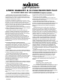
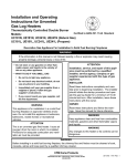
INSTALLER/CONSUMER
SAFETY INFORMATION
DO NOT INSTALL AN APPLIANCE IN THIS FIREBOX, UNLESS THIS FIREBOX MEETS
THE MINIMUM DIMENSIONS
REQUIRED FOR THE INSTALLATION.
WARNING: If the information in
this manual is not followed
exactly, a fire or explosion may
result causing property damage, personal injury or loss of
life.
™
Ventless Fireboxes
Models: UVSRC36
UVSRC42
FOR USE ONLY WITH A LISTED,
GAS-FIRED, UNVENTED, DECORATIVE ROOM HEATER NOT TO
EXCEED 40,000 BTU/H.
DO NOT BUILD A WOOD FIRE.
DUE TO HIGH TEMPERATURES,
THE APPLIANCE SHOULD BE
LOCATED OUT OF TRAFFIC
AND AWAY FROM FURNITURE
AND DRAPERIES.
Do not attempt to modify or alter
the construction of the appliance
or its components. Any modification or alteration of construction
may void the warranty of these
units.
Do not store or use gasoline or
other flammable vapors and
liquids in the vicinity of this or any
other appliance. Improper service
or maintenance can cause injury
or property damage. Refer to this
manual. For assistance or additional information, consult a
qualified installer, service agency
or the gas supplier.
Carefully review the instructions
supplied with the decorative type
unvented room heater for the
minimum fireplace size requirement.
2068
Homeowner's Installation
and Operating Manual
DE S I GN
These Ventless Fireboxes are design certified
to ANSI 21.91.2001, and are for use with any
ANSI Z21.11.2a Unvented Room Heaters.
CE
RTIFI E D
CFM Specialty Home Products
410 Admiral Blvd. • Mississauga, Ontario, Canada L5T 2N6 • 905-670-7777
www.majesticproducts.com • www.vermontcastings.com
INSTALLER: DO NOT DISCARD THIS MANUAL - Leave in fireplace for homeowner.
20002068 2/04 Rev. 10
UVSRC Series Fireboxes
Description
The UVSRC models are ventless fireboxes designed for installation with any ventless gas log set certified to
ANSI Z21.11.2a standards. Each model comes with a choice of optional hoods. Hood types may be used
depending on the combustible mantel clearance above and in front of the firebox. (See the Accessories on Page
12 for details.)
Available Models:
UVSRC36 - Radiant Circulating Model
UVSRC42 - Radiant Circulating Model
For Your Safety
Do not place clothing or other flammable material on or near the appliance.
Children and adults should be alerted to the hazards of high surface temperatures and should stay away to
avoid burns or clothing ignition.
Young children should be carefully supervised when they are in the same room as the appliance.
Table of Contents
Description and Available Models .................... 2
Specifications and Framing ............................... 3
General Information .......................................... 4
Clearances ........................................................ 5
Installation ......................................................... 6
Maintenance .................................................... 10
Replacement Parts .......................................... 11
Accessories ..................................................... 12
2
20002068
UVSRC Series Firebox
UVSRC36 Series Firebox Specifications
Rough
Opening
Depth
24"
47"
19³⁄₄"
22¹⁄₂"
⁵⁄₈"
¹⁄₂"
18¹⁄₂"
22"
33³⁄₄"
Rough
Opening
Height
47"
66¹⁄₄"
33¹⁄₄"
Rough Opening Width 41"
⁵⁄₈" Recessed
Nailing Flange
¹⁄₂"
7¹⁄₂"
38"
38¹⁄₂"
7¹⁄₂"
36"
Outside Air
23"
Gas Line
Access
14"
Gas Line
Access
9⁵⁄₈"
3"
Electrical
Access
9⁵⁄₈"
7¹⁄₂"
6³⁄₄"
10⁵⁄₈"
10⁵⁄₈"
40"
FP605a
Fig. 1 UVSRC36 Series Firebox specifications and framing dimensions.
UVSRC42 Series Firebox Specifications
Rough
Opening
Depth
26¹⁄₄"
50"
¹⁄₂"
22¹⁄₂"
⁵⁄₈"
22"
36"
Rough
Opening
Height
50"
70¹⁄₂"
⁵⁄₈" Recessed
Nailing Flange
Rough Opening Width 47"
¹⁄₂"
7¹⁄₂"
Outside
Air
38"
38¹⁄₂"
7¹⁄₂"
42"
23"
Gas Line
Access
14"
Gas Line
Access
Electrical
Access
9⁵⁄₈"
3"
6³⁄₄"
10⁵⁄₈"
9⁵⁄₈"
7¹⁄₂"
10⁵⁄₈"
46"
FP605b
Fig. 2 UVSRC42 Series Firebox specifications and framing dimensions.
20002068
3
UVSRC Series Fireboxes
General Information
DO NOT BURN WOOD OR OTHER
MATERIALS IN THESE FIREBOXES.
General Information
The installation must conform with local codes or, in the
absence of local codes, with the National Fuel Gas
Code, ANSI Z223.1 (latest edition) and with the National Electrical Code, ANSI/NFPA70 (latest edition).
NOTE: Installation and repair should be done by a
qualified service person. The firebox should be inspected before use and at least annually by a qualified
service person. More frequent cleaning may be required due to excessive lint from carpeting, bedding
material, etc. It is imperative that control compartment,
burners, and circulating air passageways of the firebox
be kept clean.
Any safety screen or guard removed for servicing a
firebox must be replaced prior to operating the firebox.
Provide adequate combustion and ventilation air.
The flow of combustion and ventilation air MUST NOT
be obstructed.
Provide adequate clearance around air openings into
the combustion chamber and adequate accessibility
clearance for servicing and proper operation. NEVER
obstruct the front opening of the firebox.
These models MAY NOT be installed in OEM mobile
homes.
These models MAY BE installed in a bedroom
provided the logset installed in the unit is certified
and rated at 10,000 BTU's or less.
These models MAY NOT be installed in a bathroom.
Glass doors are NOT to be used on these fireboxes.
Installation Precautions
This CFM Specialty Home Products firebox and its
components have been tested and will operate safely
when installed in accordance with this installation
Manual. Read all instructions before starting installation, then follow these instructions carefully during
installation to maximize firebox benefit and safety.
4
Report to your dealer any parts damaged in shipment.
This firebox is a highly engineered system. Unless you
use CFM Corporation components which have been
designed for the system, you may create a possible fire
hazard.
CFM Specialty Home Products warranty will be
voided by, and CFM Specialty Home Products
disclaims any responsibility for, the following
actions:
• Installation of any damaged firebox.
• Modification of the firebox or any of the
component parts thereof.
• Installation other than as instructed by CFM
Specialty Home Products
• Installation and/or use of any component part
or accessory not manufactured or approved
by CFM Specialty Home Products in combination or assembly with a Majestic Fireplaces
firebox, notwithstanding any independent
testing laboratory or other third party approval of such component part or accessory.
Any such action may create a possible fire hazard.
Consult your local building codes.
Proposition 65 Warning: Fuels used in gas,
woodburning or oil fired appliances, and the products
of combustion of such fuels, contain chemicals known
to the State of California to cause cancer, birth
defects and other reproductive harm.
California Health & Safety Code Sec. 25249.6
Fireplace Screen
The fireplace screen must be in place when the firebox
is operating, and unless other provisions for combustion
air are made, the screen must have openings for the
introduction for combustion air.
WARNING: Be sure to read complete
Vent-Free Gas Log Heater and Vent-Free
Fireplace Installation and Operating
Instructions before installing this product.
20002068
UVSRC Series Firebox
3a
UVSRC w/2" Hood
Dim. UVSRC36
A
36"
B
17"
C
12"
D
14"
E
8³⁄₄"
F
1¹⁄₂" max.
UVSRC w/ 4" Hood
3b
Ceiling
Ceiling
42"
42"
A
A
UVSRC42
42"
20"
16¹⁄₂"
15"
11"
1¹⁄₂" max.
11" Min.
11" Min.
Combustible Perpendicular Wall
Front View
Combustible Perpendicular Wall
Front View
Drywall
Drywall
8"
8"
Mantel
Shelf
Mantel
Shelf
¹⁄₂"
¹⁄₂"
F
F
B
D
E
C
Standoff
Standoff
2" Hood
Seal with noncombustible
material
Side View
4" Hood (Includes Glass Hood)
Seal with noncombustible material
Side View
FP604a
Fig. 3 Clearances to combustibles.
Finished Wall
Combustible Mantel
Trim Leg
Clearances
Combustible
Mantel Trim Leg
Sidewall Clearances:
The clearance from the side of the firebox to any
combustible wall extending in front of the unit should
not be less than 11". (Fig. 3)
Back Wall Clearances:
Firebox
2"
6"
3¹⁄₄"
3¹⁄₄"
8"
Noncombustible
Facing Material
The firebox may be placed against a combustible back
wall.
Hood
Ceiling Clearances:
The ceiling height should not be less than 42" from the
top of the fireplace opening. (Fig. 3)
Mantel Clearances:
A 4" hood is furnished with each model firebox. This
hood MUST BE INSTALLED before using the firebox, if
a mantel falls within the dimensions and locations
shown in Figure 3. Refer to Accessories on Page 13.
If a combustible mantel or breast plate is installed, it
must meet the clearance requirements detailed in
Figure 3. If using a mantel with trim leg, maintain
clearances detailed in Figure 4.
20002068
Front Edge of Grate
3"
FP604b
Fig. 4 Clearances to combustibles.
NOTE: When installing an ANSI Z21.11.2a ventless
appliance, the finishing material used for the mantel
must be rated at 250°F or greater.
Grate Clearance:
The minimum clearance between the front legs of the
grate and front edge of the fireplace is 3”. (Fig. 4)
5
UVSRC Series Fireboxes
Installation
Planning
In planning the installation for the firebox it is necessary
to determine where the unit is to be installed and
whether optional accessories are desired. Gas supply
piping should also be planned.
Top
Standoff
These models MAY NOT be installed in OEM mobile
homes.
Nail SideNailing
Flanges
These models MAY BE installed in a bedroom
provided the logset installed in the unit is certified
and rated at 10,000 BTU's or less.
These models MAY NOT be installed in a bathroom.
Glass doors are NOT to be used on these fireboxes.
The firebox can be mounted on any of the following
surfaces:
• A flat hard combustible surface.
• A raised platform of combustible or non-combustible material.
• A concrete block or other solid object placed
beneath each of the four corners of the appliance.
If the firebox is installed directly on carpeting, tile or
other combustible material other than wood flooring, it
should be installed on a metal or wood panel extending
the full width and depth of the unit.
At this point, you should have decided what components to include in your installation, and where the
firebox is to be located. If this has not been done, stop
and consult your dealer for assistance with this planning.
Framing
Firebox framing can be built before or after the firebox
is set in place. Framing should be positioned to accommodate wall covering and firebox facing material. The
firebox framing should be constructed of 2 x 4 or
heavier lumber. The framing headers may rest on the
top of the firebox standoffs. Refer to Figures 1 & 2 for
firebox framing dimensions.
Anchor Firebox Into Position
To prevent shifting of the firebox and to maintain
sealing (described later), anchor the firebox.
FP606a
Fig. 5 Fasten firebox in position using the nailing flanges.
Installing Outside Air Kit
An outside air kit may be installed in all UVSRC Series
fireboxes. If desired, or if local codes mandate the use
of an air kit, then an AKU1 is required to complete the
installation (from air kit to the outdoors). If the outside
air kit is to be used, the AKU1 MUST be installed
BEFORE the fireplace is enclosed. Refer to the AKU1
instructions for field installation.
Connect the Gas Line
Gas access holes are provided on both sides of the
firebox.
Check gas valve type. Use only the gas type indicated
on the gas log rating plate. If the gas listed on the plate
is not your type of gas supply, DO NOT INSTALL.
Contact your Dealer for proper model.
Always use an external regulator for all LP fireboxes to
reduce the supply tank pressure to a maximum of 14"
w.c. This is in addition to the regulator fitted to the ventfree heater.
WARNING: CONNECTION DIRECTLY TO
AN UNREGULATED LP TANK CAN
CAUSE AN EXPLOSION.
For final connection of the gas log heater to the gas line
see Section 5 and Figure 6.
Use the four fastening tabs provided with the firebox
and nails or other suitable fasteners to secure the
firebox to vertical framing members. (Fig. 5)
6
20002068
UVSRC Series Firebox
Electrical Connection
1/2" Gas Supply
1/2" x 3/8" Shut-Off Valve
The UVSRC36/42 with optional fan requires 120VAC
electrical hook-up.
3/8" Nipple
3/8" Union
3/8"
Nipple
FP598
Fig. 6 Typical gas supply line.
Install Gas Log Heater
1. Connect a shutoff valve, union and any required
approved fittings (See NOTE below) between the valve
and the gas line.
Access to the gas line on the UVSRC Series firebox is
made through the left or right side of the firebox.
CAUTION: All wiring should be done by a qualified
electrician and shall be in compliance with all local,
city and state building codes. Before making the
electrical connection, make sure that the main
power supply is disconnected. The firebox, when
installed, must be electrically grounded in accordance with local codes or, in the absence of local
codes, with the National Electrical Code ANSI/NFPA
70 (latest edition).
EB1 Receptacle Hook-Up
Wiring should be installed by a certified
electrician.
Turn off circuit breaker before wiring
models.
From the inside of the firebox, locate the knockout on
the firebrick - be sure you are on the appropriate or gas
line side of the firebox. Using a flat bladed screwdriver
or small chisel and hammer, carefully tap around the
knockout until it loosens and falls out.
Once the firebox is secured, complete wiring the fan kit.
Remove knockout in the center of the back of the EB1
and install listed cable clamps. Feed electrical wire
through cable clamp leaving approximately 6" of wire
exposed through the EB1. Secure the cable clamp to
the wire.
2. Install the Vent-Free Gas Log Heater exactly as
described in the instructions for the heater. If, for any
reason, you do not have these instructions, contact
your dealer or manufacturer for another copy.
Attach white wire from power source to one wire of
receptacle and secure with a nut. Attach black wire from
power source to the other wire of the receptacle and
secure with a nut. Be sure nuts are tightened securely.
NOTE: The gas line connection to the log set can be
made with 3/8" copper tubing approved for propane or
natural gas, 1/2" rigid pipe, or an approved flex connector. Because some municipalities have additional local
codes, it is always best to consult your local authority.
Secure the EB1 assembly to the inside of the electrical
box cover plate using 2 screws. Attach the cover to the
face of the EB1 while being careful to position the
excess wire completely within the EB1. Attach the
coverplate to the firebox. (Fig. 7)
U.S. INSTALLATIONS — Follow local codes and the
National Fuel Gas Code ANSI Z223.1.
Always check for gas leaks with a mild
soap and water solution. Do not use an
open flame for leak testing.
When using copper or flex connector, use only approved fittings. Always provide a union so that the
gas line can easily be disconnected for burner or fan
servicing. See gas specifications for pressure details
and ratings.
Inside
Electrical Box
Front o
f Unit
(Left Sid
e)
Outside
Unit
t of
Fron
FP580
Fig. 7 Junction box (EB-1) hook-up.
20002068
7
UVSRC Series Fireboxes
Fan
Hard Flat
Surface
Black
White
Ground
FP579
Fig. 8 Wiring diagram.
Install Fan Kit Assembly
Refer to the Fan Kit (Model FK12) installation instructions for field installation. (Fig. 8)
WHEN INSTALLED, THE FIREBOX MUST BE
ELCTRICALLY CONNECTED AND GROUNDED (See
Figure 14) IN ACCORDANCE WITH LOCAL CODES,
OR IN THE ABSENCE OF LOCAL CODES:
U.S. INSTALLATIONS — Follow local codes and the
National Electrical Code ANSI/NFPA No. 70.
Insulation
Platform
Cold Climate Insulation
In cold climates, insulation of the enclosure around the
firebox is suggested to avoid problems with cold air.
FP607a
Fig. 9 Insulation between firebox and platform.
Insulating the enclosure around the firebox is
recommended, but not a requirement.
The following steps are suggested to minimize cold air
problems.
Insulation
Insulate the base of the firebox with a noncombustible
insulation. This step is particularly important for outside
wall installations over concrete slab floor construction. If
a platform is used to raise the firebox, the insulation
should be placed on top of the platform before the
firebox is set. (Fig. 9)
Plywood
Support
Refer to Page 5, Figure 3 for minimum clearances to
combustibles.
Inspect joints of the firebox as well as the points of
sealing between the firebox and the finishing materials.
Any cracks should be sealed with noncombustible
caulking or insulation. Refer to Figures 9 and 10 for
details of sealing between the firebox and finishing
materials.
When a firebox is installed in a chase or on an outside
wall, the enclosure should be insulated like any other
outside wall of the home. Plywood or hardboard may be
placed on the standoffs and insulation placed on this
surface. (Fig. 10) Noncombustible insulation, such as
vermiculite, Pearlite, Zonalite or unfaced fiberglass
insulation, may be used between the exterior of the
firebox and chase drywall up to 1" from the top of the
firebox.
8
FP608a
Fig. 10 Additional insulating methods.
20002068
UVSRC Series Firebox
Finishing
Refer to Page 5, Figure 3 for allowable finishing materials and clearances to combustibles.
All joints, top, bottom and sides, where the wall or
decorative facing material meets the firebox surround
must be completely sealed with a noncombustible
material. (Figs. 11-14)
NOTE: Do not install combustible materials on any
of the black fireplace surround.
Finished Wall
2 x 4 Finished Header
Must be sealed with
noncombustible
material
Standoff
Noncombustible
Decorative Facing
Surround
Hearth Extension
FP610a
A hearth extension may be used but is not required for
these fireboxes.
Fig. 13 Appliance surround flush with finished wall.
A raised hearth extension may be used as shown in
Figure 15.
Finished Wall
Noncombustible
Caulking/Insulation
Noncombustible
Decorative
Facing
2x4
Framing
2 x 4 Finished
Header
Covered Wall
Must be sealed with
noncombustible material
Standoff
Surround
Standoff
FE107
Finishing Material
Fig. 11 Sealing spaces between appliance and finishing
materials.
Finished Wall
See mantel drawing for
shelf-to-surround
dimension
Mantel Shelf
Stud
Hearth
Brick
Hearth
Extension
2x4
Seal with noncombustible
material ONLY
FP611a
Fig. 14 Facing on firebox flush with finished wall.
Standoff
Surround
Fireplace
Front
Top View
Side View
Noncombustible
Hearth Extension
¹⁄₂"
Combustible
Platform
2 x 4 Stud
Finished Wall
Fireplace Front
Surround
May be sealed with
noncombustible material
FP612b
FP568a
Fig. 15 Side view of firebox with raised hearth extension.
Fig. 12 Surround flush with finished wall.
20002068
9
UVSRC Series Fireboxes
Install Hood
A hood is furnished with the firebox. Optional hoods
listed on Page 12 may be installed as shown in Figures
16 and 17. Failure to do so may create a fire hazard.
WARNING: When the black surround is covered by a
brick surface, (Figure 16), use an extended hood. The
hood should extend out to the brick surface (Figures 16
and 17) and be attached to the firebox. The maximum
brick to noncombustible surface that may extend out
past the black surround surface is 4¹⁄₄".
4¹⁄₄" Max.
Brick Surface
Extended Hood
FP612a
Fig. 16 Side view of firebox with extended hood.
Maintenance
Top of Fireplace
Surround
Keep the control compartment, logs and burner area
surrounding the logs clean by carefully vacuuming or
brushing at least twice a year or as necessary.
THE LOGS CAN GET VERY HOT — HANDLE ONLY
WHEN COOL.
Always turn off the gas to the pilot before cleaning. For
relighting, refer to the lighting instructions located on
the Rating Plate of the gas log set.
Never obstruct the flow of combustion and ventilation
air. Keep the front of the appliance clear of all obstacles
and materials.
Leave at least a 36" clearance from the front of the
firebox to any room furnishings.
Slot
Screw
(Fastens to side rail
from inside hood)
Use
Bottom
Slot
Screw
FP613a
Fig. 17 Hood location.
10
20002068
UVSRC Series Firebox
1b
1a
6
8
2
3
4
5
7
2068
CFM Specialty Home Products reserves the right to make changes in design, materials, specifications, prices and discontinue colors and products at any time, without
notice.
UVSRC36/42
Ref. Description
1a. Right Screen Assembly (Screens and Rod)
1b. Left Screen Assembly (Screens and Rod)
2. Brick - Left Side
3. Brick - Back
4. Brick - Ash Lip
5. Brick - Right Side
6. EB1 Junction Box
7. O.S.A. Assy
8. Hood - 4", Black
20002068
UVSRC36
20002084
20002081
20002008
20002006
20002017
20002007
EB1
20003076
UV36BH4
UVSRC42
20002084
20002081
20002021
20002019
20001857
20002020
EB1
20003076
UV42BH4
11
UVSRC Series Fireboxes
Accessories
The following accessories for these appliances are available from your local Majestic Fireplaces distributor. Each
accessory comes with a separate installation instruction for mounting to the particular firebox. Be sure to
read each instruction thoroughly before installing.
See your Majestic Fireplaces distributor or dealer for other finishing options such as marble and mantels — available
in a wide selection of styles.
Accessory
Description
Model Number
Fan Kit
Provides forced air flow
FK12
Variable
Speed Control
Provides speed adjustment of fans
SCVS
Completes connection from air kit to out-of-doors
AKU1
Outside Air
Termination
Black Finish
Polished Brass
Finish
UV36BH2
UV42BH2
UV36PH2
UV42BH2
2" Hood
For mantel 8" wide by 10" high
4" Hood
For mantel 8" wide by 10" high
4" Hood
Glass Hood for mantel 8" wide by 10" high
UV36GH4
UV42GH4
4" Hood
Extended hood for brick facings
and mantel 8" wide by 10" high
UV36BH4E
UV42BH4E
UV36PH4
UV42PH4
UV36PH4E
UV42PH4E
CAUTION: This firebox is a highly engineered system, and, as such, must be operated only with CFM Specialty Home Products approved components. If you use an unapproved component to make any modifications, you may create a possible fire hazard and will void the CFM Specialty Home Products warranty. In
addition, such action may void the coverage provided by the owner’s insurance.
Contact CFM Specialty Home Products for questions
concerning prices and policies covering replacement parts.
Parts may be ordered through your Majestic Fireplaces
distributor or dealer.
You will need the following information when ordering
replacement parts:
1. The firebox model number.
2. The firebox serial number.
3. A description of the part.
Should you need additional information beyond what your
dealer can furnish, contact:
CFM Specialty Home Product
410 Admiral Blvd.
Mississauga, Ontario
Canada L5T 2N6
Attn: Customer Service
12
FIREBOX
Model and serial numbers are listed on the
rating plate (located on right side of combustion
chamber).
Record your model and serial numbers here for
future reference:
Model #
____________________________
Serial #
____________________________
VENT-FREE LOG HEATER
Record your model and serial numbers here for
future reference:
Model #
____________________________
Serial #
____________________________
20002068
UVSRC Series Firebox
™
LIMITED WARRANTY & 30 YEAR PROTECTION PLAN
For MAJESTIC FIREPLACES® PRE-ENGINEERED Fireplace Systems
CFM Specialty Home Products warrants its MAJESTIC
FIREPLACES® Pre-Engineered Fireplace (“Fireplace”) and the
CFM Specialty Home Products supplied firegrate, glass doors,
outside air system, fan motor, and liners to be free from defects
in material or workmanship, as follows:
A. Fireplace and Chimney Components: (exclusive of CFM
Specialty Home Products-supplied firegrate, glass doors, outside
air system, fan motor, and liners all of which are covered by
separate warranties under paragraphs B through D below): At its
option for a period of thirty (30) years from the date the Fireplace
is installed, CFM Specialty Home Products will;
(1) For a period of five (5) years from the date the Fireplace is
installed, CFM Specialty Home Products, at its option, will repair
or replace any defective part without charge.
(2) Thereafter, through the 10th year after the date the
Fireplace is installed, if replacement parts are available, CFM
Specialty Home Products will provide a replacement for any
defective part without charge for the part itself. The consumer
must pay for everything else other than the part.
(3) Thereafter, through the 30th year after the date the
Fireplace is installed, if replacement parts are available,CFM
Specialty Home Products will provide a replacement for any
defective part at a cost to the consumer of CFM Specialty Home
Products then current list price, FOB CFM Specialty Home
Products factory.
B. Firegrate, Glass Doors, Outside Air System:
For a period of 90 days from the date the Fireplace is installed
CFM Specialty Home Products, at its option, will provide a
replacement for any defective part, without charge for the part
itself, FOB CFM Specialty Home Products factory, (The consumer must pay for everything else other than the part,).
C. Fan Motor:
(1) For a period of one (1) year from the date the Fireplace is
installed, CFM Specialty Home Products, at its option, will repair
or replace any defective part without charge.
(2) Thereafter, through the 30th year after the date the
Fireplace is installed CFM Specialty Home Products, at its
option, if replacement parts are available, will provide a replacement for any defective part at a cost to the consumer of CFM
Specialty Home Products then current list price, FOB CFM
Specialty Home Products factory.
D. Liners (Refractory or Metal):
(1) For a period of two (2) years from the date the Fireplace is
installed, CFM Specialty Home Products, at its option, will repair
or replace any defective part without charge.
(2) Thereafter, through the 30th year after the date the
Fireplace is installed CFM Specialty Home Products, if replacement parts are available, will provide a replacement for any
defective part at a cost to the consumer of CFM Specialty Home
Products then current list price, FOB CFM Specialty Home
Products factory.
This warranty is subject to the following conditions and limitations:
(1) This warranty is extended only to a Fireplace installed in
the continental United States, the state of Alaska and Canada;
only if and so long as the Fireplace is installed according to the
installation instructions furnished with the Fireplace, and
operated at all times under normal conditions, use and service
20002068
according to the operative instructions furnished with the
Fireplace, and only if and so long as the Fireplace is not
removed from its original installation.
(2) This warranty is non-transferrable, and is made to the
original owner, provided that the purchase was made through an
authorized supplier of the Company.
(3) The sole and exclusive remedies for breach of any
warranties hereunder shall be for the repair, replacement or
provision of a replacement part at CFM Specialty Home Products
then current list price, FOB CFM Specialty Home Products
factory, for any defective part as specified in paragraphs A
through D.
(4)CFM Specialty Home Products shall not be liable for
damage from any smoking of a MAJESTIC FIREPLACES PreEngineered Fireplace System related to environmental geographic conditions (such as, for example, nearby structures or
roof peaks, trees, hills, or mountains), inadequate ventilation, or
negative air pressure in the place where the Fireplace system is
installed, related to any mechanical system (such as, for
example, furnaces, fans, air conditioners, clothes dryers, etc.)
(5) Except as otherwise expressly specified in paragraphs A
through D, NONE OF THESE WARRANTIES COVER, AND
CFM SPECIALTY HOME PRODUCTS SHALL NOT BE RESPONSIBLE FOR, ANY CONSTRUCTION, INSTALLATION,
LABOR, TRANSPORTATION OR OTHER COSTS OR EXPENSES ARISING FROM A DEFECTIVE PART, ITS REPAIR OR
REPLACEMENT OR OTHERWISE, NOR SHALL CFM SPECIALTY HOME PRODUCTS IN ANY EVENT BE RESPONSIBLE
FOR ANY INDIRECT, INCIDENTAL OR CONSEQUENTIAL
DAMAGES EXCEPT TO THE EXTENT REQUIRED BY LAW.
Some states do not allow the exclusion or limitation of incidental
or consequential damages, so this exclusion or limitation may not
apply to you.
NO IMPLIED WARRANTIES, INCLUDING THE IMPLIED
WARRANTIES OF MERCHANTABILITY AND FITNESS FOR A
PARTICULAR PURPOSE, SHALL REMAIN IN EFFECT AFTER
THE EXPIRATION OF THE WARRANTIES SET FORTH IN
PARAGRAPHS A THROUGH D. Some states do not allow
limitations on how long an implied warranty lasts, so this
limitation may not apply to you.
In order to obtain performance of any of the above warranty
obligations write to CFM Specialty Home Products at this
address:
CFM Specialty Home Products
410 Admiral Blvd.
Mississauga, Ontario, Canada L5T 2N6
Attention: Director of Warranty Services
Since local building requirements may vary greatly throughout
the country, users of CFM Specialty Home Products products
should determine in advance whether there are any building
code restrictions on the use of a specific product. CFM SPECIALTY HOME PRODUCTS MAKES NO REPRESENTATION
OR WARRANTY REGARDING, AND SHALL NOT BE RESPONSIBLE FOR, ANY BUILDING CODE COMPLIANCE.
The foregoing warranties give you specific legal rights and you
may also have other rights which vary from state to state.
13
CFM Specialty Home Products
410 Admiral Blvd. • Mississauga, Ontario, Canada L5T 2N6 • 905-670-7777
www.majesticproducts.com • www.vermontcastings.com
© CFM Specialty Home Products