1
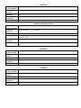
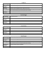
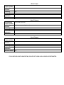
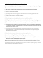
www.altfuelconv.com website
[email protected] email
1100 King Rd P.O Box 351330
Toledo,Ohio,43635-1330
Green Conversion Kit for Small Engines AF2
The AltFuel Green Conversion Kit is engineered for use on only engines that are in excellent
running order. Due to the characteristics of propane vapor fuel engines that may run ok on
gasoline but have underlying problems will not run as well on propane. Engines that have lowered
compression due to wear will run near full power on gasoline but will not be able to make full
power on propane vapor due to compression loss.
AltFuel does not recommend the conversion of engines used in a commercial setting that have
over 500 hours unless the engines have been excellently maintained and have near factory
compression.
The AltFuel Green Conversion kit will not fix problems that already exist in an engine.
The AF2 Regulator System is designed to easily convert all overhead cam (OHC) and overhead
valve (OHV) engines by utilizing an Intake Adapter placed behind the carburetor to deliver
propane vapor fuel. The correct Intake Adapter for the engine being converted will need to be
selected from our easy to use list.
Do not use MAPP gas or MAPP gas cylinders (tall slender tanks) on the AltFuel Green Conversion Kit.
***PATENT PENDING***
Thank you for purchasing the AltFuel Green Conversion Kit
The AltFuel Conversion Kit Model 2 consists of 3 to 4 key components, depending on the engine:
1) Regulator system with 1 regulator assembly, 3 zip ties, 1 AltFuel “No Gas” sticker, and 1 set of Model 2 instructions
2) ¼” certified rubber LP fuel line (custom length dependent on application)
3) Aluminum adaptor plate (dependent on engine model)
4) 1 restrictor plug is needed for 23-45 hp only
General Notifications
Any engines you intend on converting to propane fuel should be run on gasoline before
the installation of the AltFuel conversion system to ensure the engine is running correctly.
NOTE: Please check engine with applicable tachometer to make sure the engine is set at
the factory recommended speed settings.
If the engine is not running correctly please resolve the problems before installation of
the AltFuel Conversion System.
NOTE: If you are not sure how to adjust valves, adjust governors, or anything else
pertaining to basic engine knowledge, please contact your local industry certified
technician for assistance.
Prior to Installation
For best engine life and performance, we recommend you check your oil and replace it with a highgrade synthetic blend of motor oil applicable to your engine before installing the AltFuel Green
Conversion Kit. Any engine that you intend on converting to propane fuel should be in good running
condition before attempting to install this kit.
Check compression. Compression must be above 120psi. If compression is below 120psi the
performance of the engine on propane vapor will be less than optimal. Engines with significantly
lower than factory compression will have less than optimal performance on propane vapor fuel.
Inspect valves and adjust to manufacture specifications.
On all Kawasaki engines adjust valves .002 over factory settings on all twin cylinder engines per
Kawasaki Technical Manual or refer to Kawasaki technician
For best engine life we recommend running high synthetic oil.
All spark plugs must be changed to platinum/iridium spark plugs.
The stock spark plugs used in gasoline utility engines rely on the carbon in gas to help arc the plug.
Since there is no carbon in propane fuel, the spark plug is the only conductor of the electrical
current, causing the standard plug to burn out sooner. We therefore suggest frequent maintenance
of the spark plugs used in engines which have the AltFuel Conversion Kit.
Inspect spark plug gap and adjust to .035-.040 gap. Clean or replace the spark plug to ensure proper
easy starts.
Check air filter. Air filter must be new or clean and free of dirt and debris. Replace if needed.
Note: Some engines and applications may need to be modified in order to achieve optimum
performance.
Specialty Tools Needed
1 – Siphon
1 – Gas tank to contain siphoned gasoline
1 – Socket set
1 – Tachometer
1 – Compression test kit
1 – Teflon tape
1 – Flat head screwdriver and hex head screw drivers
1 – Test cylinder: For 1-13hp engine conversion any propane cylinder will work. For 13-20hp
conversion a 20lb vapor aluminum/steel propane cylinder (Buffer cylinder) or larger will be needed
to test the application. For 20-45hp conversions a 33lb vapor cylinder is needed.
Dual Fuel Options
If you happen to run out of propane, you have the option to run your engine on gasoline. Simply
fill the fuel tank, turn the gasoline on/off valve on, and start. DO NOT RUN PROPANE AND
GASOLINE AT THE SAME TIME! To return to propane fuel, siphon all gasoline from the fuel tank
and run the engine so all gasoline is consumed. WE ONLY RECOMMEND RETURNING TO
GASOLINE IN AN EMERGENCY.
Warnings
The AltFuel Green Conversion kit is engineered for use on only engines that are in excellent running
order. Due to the characteristics of propane vapor fuel engines that may run ok on gasoline but
have underlying problems will not run as well on propane. Engines that have lowered compression
due to wear will run near full power on gasoline but won’t be able to make full power on propane
vapor due to the compression loss.
AltFuel does not recommend the conversion of engines used in a commercial setting that have over
500 hours unless the engines have been excellently maintained and have near factory compression.
The AltFuel Green Conversion kit will not fix problems that already exist in an engine.
If your engine is already consuming oil, or more than 1 ounce per hour run time, it needs to be
replaced or repaired. While LPG extends oil change time it still must be checked regularly and
before each use.
AltFuel cannot guarantee the performance or end result of an improperly installed kit.
The AltFuel Green Conversion Kit runs on vapor propane and can only be fueled by a vapor service
cylinder. Use of a liquid service cylinder will permanently damage the Regulator system.
If your engine is 10 Hp or higher, the regulator system must be mounted vertically. If your engine is
less than 10 Hp the regulator system must be mounted vertically.
If your engine is less than 10 horsepower it must be mounted horizontally.
AltFuel cannot guarantee the performance or end result of an improperly installed kit.
Installation Instructions
Makita/Dolmar/Robin 4-Stroke Backpack Blower
Note: Due to changes in O.E.M configurations and application/engine configurations the Intake
adapter or Orifices may need to be slightly altered for best fit and performance.
1.
2.
3.
4.
5.
6.
7.
8.
9.
10.
11.
12.
13.
14.
15.
Close gasoline on/off valve if available or empty gas tank of gasoline.
Start engine and run until all gasoline is consumed from the carburetor.
Disconnect spark plug(s).
Remove intake tube or pivot up out the way.
Remove the intake/choke assembly in order to access carburetor.
Make sure that the O-ring is in place on the carburetor flange.
Carefully thread provided orifice into the AltFuel Intake Adapter. Thread orifice in until nonthreaded section of orifice touches the surface of Intake Adapter. Do not over tighten.
Apply Teflon tape or pipe sealant to threaded fitting on the end of the AltFuel Fuel Supply Line
and carefully thread into orifice on Intake Adapter.
Place AltFuel Intake Adapter with Fuel Supply Line attached in front of carburetor with orifice
facing up.
Apply black silicone sealant to surface of intake/coke assembly touching the Intake Adapter.
Using the original screws reinstall the intake/choke assembly over the Intake Adapter.
Place intake tube back on intake/choke assembly.
Tighten clamps.
Start and run. Adjust idle screw in to achieve a higher idle rpm.
Mount Regulator System to the blower frame.
Installation Instructions
Honda GX25/GX35 1-2Hp
Note: Due to changes in O.E.M configurations and application/engine configurations the Intake
adapter or Orifices may need to be slightly altered for best fit and performance.
1.
2.
3.
4.
5.
6.
7.
8.
9.
10.
11.
12.
13.
14.
15.
16.
17.
18.
19.
20.
21.
22.
Close gasoline on/off valve if available or empty gas tank of gasoline.
Start engine and run until all gasoline is consumed from the carburetor.
Disconnect spark plug(s).
Remove air filter cover, air filter, and air filter assembly in order to access carburetor.
Remove engine cover.
Remove carburetor.
Remove intake assembly.
Replace studs in intake assembly with longer studs supplied with AltFuel stud kit.
Reassemble intake assembly.
Install carburetor back on studs, making sure throttle cable and gaskets are in place.
Make sure that the O-ring is in place on the carburetor flange.
Carefully thread provided orifice into the AltFuel Intake Adapter. Thread orifice in until
non-threaded section of orifice touches the surface of Intake Adapter. Do not over tighten.
Thread 90 degree fitting into orifice.
Apply Teflon tape or pipe sealant to threaded fitting on the end of the AltFuel Fuel Supply Line
and carefully thread into 90 degree fitting on Intake Adapter.
Place AltFuel Intake Adapter with Fuel Supply Line attached in front of carburetor with orifice
facing up.
Apply black silicone sealant to surface of intake assembly touching the Intake Adapter.
Fuel Supply Line should be mounted down and to left.
Reinstall air filter assembly, air filter, and air filter cover.
Install Regulator System below balancing point on handle, or in desired position.
Attach Fuel Supply Line to regulator System.
Attach propane source.
Start and run. Adjust idle screw in to achieve a higher idle rpm.
Engines 3-45Hp
If you have one of the following engines listed below please see page 11 Specialty Engines.
Kohler 16211-ZL8-000 or 4185306-S or 1205301
Briggs 130000 Series Utility Engine (Tillers, Go-Carts, Pump, etc.)
Tecumseh 16211-ZL8-000 (5HP-11HP engines for generators, log splitters, etc.)
Kawasaki (V-Twin Engines) AF1-792295 FX751V, FX801V, FX850V, FX921V
Note: Due to changes in O.E.M configurations and application/engine configurations the Intake
adapter or Orifices may need to be slightly altered for best fit and performance.
1.
2.
3.
4.
5.
6.
7.
Close gasoline on/off valve if available or empty gas tank of gasoline.
Start engine and run until all gasoline is consumed from the carburetor.
Disconnect spark plug(s).
Disconnect battery.
Remove air filter cover, air filter, and air filter assembly in order to access carburetor.
Remove carburetor and insulator plate.
Carefully thread provided orifice into the AltFuel Intake Adapter. Thread orifice in until nonthreaded section of orifice touches the surface of Intake Adapter. Do not over tighten. Attach 90degree elbow to orifice(s) on Intake Adapter if needed.
8.
Apply Teflon tape or pipe sealant to threaded fitting on the end of the AltFuel Fuel Supply Line
and carefully thread into orifice(s) or 90-degree elbow on Intake Adapter.
9. Note: Be sure not to stretch Governor spring. Governor spring must be replaced if stretched.
10. Install Intake Adapter between the carburetor and engine. Be sure to keep all gaskets in place and
ensure that all gaskets not damaged. The orifice side of the Intake adapter may be on the top or
bottom depending on your personal preference and/or setup of your engine/application.
11. Reassemble the carburetor system with the AltFuel Intake Adapter plate in place. Be careful to
put all gaskets back in the correct positions. (If a gasket is damaged or misplaced, it is very
important to replace it. If your gaskets are old or dirty it is recommend replace them.) Ensure all
parts are secured properly before moving to the next step.
Note: On engines with dual barrel carburetors the gaskets used behind the carburetor must seal
the area between the two holes to prevent cross-vacuum
NOTE: Follow 12a and 13a for residential use, and for commercial use follow 12b and 13b.
12a. Mount Regulator System away from direct heat or spark sources. Secure the AltFuel Green
Conversion Kit regulator system to your equipment in the desired position where the conversion
system is out of harm’s way. Make sure that the conversion kit is in a desirable position for starting and stopping purposes.
Note: If your engine is 10 horsepower or higher, the conversion kit must be mounted vertically*
12b. Remove 1# bottle adapter fitting on Regulator System and replace with 1/4MNPT by 3/8 Flare
fitting.
13a. Connect Fuel Supply Line to Regulator System.
13b. Caution: Do not install cylinder attachment line to output port of second stage regulator.
14.
Attach Cylinder Attachment line to propane cylinder.
15.
Check that all Fuel Supply Lines and Cylinder Attachment Lines are away from heat sources
and pinch points.
Restrictor Plug Installation for engines 23-45hp Single or V-twin with canister air filter assembly
1.
2.
3.
4.
5.
6.
7.
8.
9.
10.
11.
Remove mushroom cap on canister air filter assembly.
Install restrictor plug in canister opening.
Reinstall mushroom cover and tighten clamp.
Start engine and warm up for 1-2 minutes (Please see page 16 for starting
instructions)
Move the throttle to fastest position.
Check engine speed with applicable tachometer.
If engine speed is 3600 rpm no load speed can be increased for more power under load.
To increase engine speed adjust throttle cable in order to provide more tension on engine speed
controls.
The stop for throttle cable can be adjusted for increased travel.
If 3950 rpm is achieved, no further adjustment is required.
If 3950 rpm is not obtained the tabs holding the governor spring can be bent to increase
tension.
Note: Never exceed 4000 rpm for no load commercial use equipment
Note: Never exceed 3600 rpm for no load non-commercial use equipment
Note: If you are not sure on how to adjust valves, adjust governors and or anything else pertaining to
basic engine Knowledge Please contact your local Industry certified technician for help.
Note: Concerning engine speeds versus horsepower. In most situations the governor high idle no load
speed is set at the factory recommended level of 3600rpm. In some cases no load speed is set to 3800
+/- 50rpm. The primary reasons for this are:
1. Propane fuel requires higher engine speeds to achieve the same level of performance under
heavy commercial use.
2. Customer or user may believe they have lost power or wheel speed under heavy commercial
use.
3. BTU output of propane is lower than regular gasoline fuel and engine speed can compensate for
that reduction.
4. If you are not sure on how to adjust valves, adjust governors, or anything else pertaining to basic
engine knowledge, please contact your local industry certified technician for help.
Mounting of AF-2 Regulation System
The following template is a drawing of the mounting plate of AF-2.
Step 1:
Step 2:
Step 3:
Step 4:
Step 5:
Cut out the template
Place paper template on a desired location
Trace template onto desired location
Drill 2 holes in the desired location
Mount the AF-2 Conversion system
Additional parts needed:
2 ¼ 28 screws to desired length
Drill
¼ 28 drill bit
Sharpie marker
If your engine is 10hp or higher, the regulation system must be mounted vertically.
If your engine is less than 10hp the regulation system must be mounted horizontally.
TEMPLATE
Cylinder Bracketing Installation
Zero Turn Mowers
Recommended
Propane Cylinders
Tank Fitting
and Lines
Bracketing
Installation on
Application
Materials needed
33.5LB and 45.5LB vapor service horizontal cylinder, or 33.5LB and 43.5LB in vertical position
with vapor service valve installed
Left hand ACME
33LB horizontal cylinder bracket. Part AF1-33LB
Option 1: Remove gasoline tank and extend bases to accommodate 33LB bracket.
Option 2: Mount horizontally to rear of Roll-Over Protective Structure. Be sure to mount in an
area that allows you to lower and raise the ROPS.
Option 3: Mount vertically to rear or side of Roll-Over Protective Structure.
AF1-33LB bracket use (4)- ¼ inch plate steel by 36 inch wide by 8 inch tall. 3/8 x 3” bolts and lock washers and nuts. Or use (4)- 3/8” UP bolts 3” x 3” to secure AF1-33LB to plate. Use a 16” outside to outside pattern. Use (4) -3/8” x 1” bolts, lock washers and nuts. Also secure the tank guide pin to bottom of tank bracket for proper location of tank valve with 3/8” bolts supplied. This bracketing will allow the tank to be secured to roll bar applications. For fender mounts a piece of
¼” plate steel by 20” long by 10” wide will secure it to the frame or fender of the unit.
Commercial Walk Behind Mowers
Recommended
Propane Cylinders
Tank Fitting
and Lines
Bracketing
Installation on
Application
Materials needed
20LB Aluminum/Steel Cylinder or 14LB Cylinder
Right Hand ACME
20LB Vertical Cylinder Bracket. Part AF1-20LB
Remove gasoline tank and bolt to the base plate of removed gasoline tank.
(4)- 3/8” x 3” bolts and lock washers and nuts. Or use (4)- 3/8” U bolts 3” x 3”. May need ¼”
plate steel
Push Mowers
Recommended
Propane Cylinders
Tank Fitting
and Lines
Bracketing
Bracketing Notes
Installation on
Application
Materials needed
1LB Cylinder (Short Fat) or 5LB Cylinder
1LB direct mount to Regulator System. 5LB uses AF1-120-24
5LB Cylinder Bracket. Part AF1-901 or AF1-120-24
Remove pin from bracket. Place collar of 5LB cylinder over plastic bushings. Push pin through
hole in cylinder collar and over bracket between plastic bushings.
Clamp 5LB Cylinder Bracket to handlebars.
None
Putting Green Mowers
Recommended
Propane Cylinders
Tank Fitting
and Lines
Bracketing
Bracketing Notes
Installation on
Application
1LB Cylinder (short fat) or 5LB Cylinder
1LB direct mount to Regulator System. 5LB uses AF1-120-24
1LB direct mount to Regulator System. 5LB uses AF1-120-24
Remove pin from bracket. Place collar of 5LB cylinder over plastic bushings. Push pin through
hole in cylinder collar and over bracket between plastic bushings.
Clamp 5LB Cylinder Bracket to handlebars.
ATV/Off-Road Vehicles
Recommended
14LB Cylinder
Propane Cylinders
Tank Fitting
Right Hand ACME
and Lines
Bracketing
33LB Horizontal Cylinder Bracket AF1-33LB
Bracketing Notes
33LB Horizontal Cylinder bracket will need to be modified to fit the 14LB cylinder. Bolt to stable
a and sound Flat steel
Installation on
N/A Custom
Application
Materials needed (4) 3/8” x 3” bolts and lock washers and nuts. Or use (4) 3/8” UP bolts 3” x 3”. May need ¼” steel plate
Back Pack Blowers
Recommended
Propane Cylinders
Tank Fitting
And Lines
Bracketing
Bracketing Notes
Installation on
Application
Materials Needed
1LB Cylinder (short fat)
1LB direct mount to Regulator System
None
None
None
None
Concrete Buggies
Recommended
Propane Cylinders
Tank Fitting
And Lines
Bracketing
Bracketing Notes
Installation on
Application
Materials Needed
14LB/33LB Cylinder Horizontal Vapor
Left Hand ACME fitting. Right Hand ACME fitting
33LB Horizontal Cylinder Bracket. AF1-33LB
33LB Horizontal cylinder bracket will need to be modified to fit the 14LB cylinder. Please bolt to
stable and sound Flat steel
Mount to flat piece of steel in a clear area of vehicle
(4)-3/8” x 3” bolts and lock washers and nuts. Or use (4)-3/8” U bolts 3” x 3”, may need ¼” plate steel
Ditch Witches
Recommended
Propane Cylinders
Tank Fitting
and Lines
Bracketing
Installation on
Application
Materials needed
14LB/33LB Cylinder Vertical Vapor
Right Hand ACME to POL Fitting. Part: AF1-220RH (residential use)
Right Hand ACME . Part HDL-RH (commercial use)
33LB Horizontal Cylinder Bracket. Part No: AF1-33LB 20LB Vertical Cylinder Bracket. Part No.
AF1-20LB
Mount vertically to flat piece of steel on front of machine to left or right of machine.
33LB Horizontal cylinder will need to be Modified to fit the 14lb cylinder. Please bolt to stable
sound Flat steel
Qty. 4 - 3/8 x 3in bolts and lock washers and nuts
Or use qty. 4 - 3/8 in U bolts 3 in x 3in May need 1/4 in plate steel
Generators
Recommended
Propane Cylinders
Tank Fitting
And Lines
Bracketing
Installation on
Application
Materials Needed
Any Cylinder
N/A
N/A
N/A
N/A
Golf Carts and Utility Vehicles
Recommended
Propane Cylinders
Tank Fitting
and Lines
Bracketing
Bracketing Notes
Installation on
Application
Materials needed
14LB/33LB Cylinder Horizontal Vapor
Right Hand ACME . Left hand ACME
AF1-33LB
33LB Horizontal cylinder bracket. Will need to be modified to fit the 14LB cylinder. Bolt to stable
sound Flat steel
Mount to flat piece of steel in a clear area of vehicle
(4)- 3/8” x 3” bolts and lock washers and nuts. Or use (4)- 3/8” U bolts 3”x3”. May need ¼” plate
steel
Compressor
Recommended
Propane Cylinders
Tank Fitting
and Lines
Bracketing
Installation on
Application
Materials needed
Any cylinder
Recommended
Propane Cylinders
Tank Fitting
And Lines
Bracketing
Installation on
Application
Materials Needed
1LB Cylinder (short fat)
N/A
N/A
N/A
N/A
Ice Augers
N/A
N/A Custom
N/A
N/A
Lawn Tractors
Recommended
Propane Cylinders
Tank Fitting
And Lines
Bracketing
Bracketing Notes
Installation on
Application
Materials Needed
20LB Aluminum/Steel Cylinder/33LB Cylinder Horizontal Vapor
Left Hand ACME fitting. Right hand ACME fitting.
33LB Horizontal Cylinder Bracket AF1-33LB. 20LB Vertical Cylinder Bracket AF1-20LB
33LB Horizontal cylinder bracket will need to be modified to fit the 14LB cylinder. Bolt to stable
sound Flat steel.
N/A Custom
(4)-3/8”x3” bolts and lock washers and nuts. Or use (4) 3/8” U bolts 3”x3”. May need ¼” steel plate.
Lawn Vacuums
Recommended
Propane Cylinders
Tank Fitting
And Lines
Bracketing
Bracketing Notes
Installation on
Application
Materials Needed
1LB Cylinder (short fat) or 5LB Cylinder
1LB direct mount to Regulator System. 5LB uses AF1-120-24
1LB direct mount to Regulator System, 5LB uses AF1-120-24
Remove pin from bracket. Place collar of 5LB cylinder over plastic bushings. Push pin through
hole in cylinder collar and over bracket in between plastic bushings.
Mount on top of solid bar/stable structure
N/A
Leaf Blowers
Recommended
Propane Cylinders
Tank Fitting
And Lines
Bracketing
Bracketing Notes
Installation on
Application
Materials Needed
1LB Cylinder (short fat) or 5LB Cylinder
1LB direct mount to Regulator System. 5LB uses AF1-120-24
1LB direct mount to Regulator System. 5LB uses AF1-120-24
Remove pin from bracket. Place collar of 5LB cylinder over plastic bushings. Push pin through
hole in cylinder collar and over bracket between plastic bushings.
Clamp 5LB cylinder Bracket to handlebars
N/A
Log Splitters
Recommended
Propane Cylinders
Tank Fitting
And Lines
Bracketing
Bracketing Notes
Installation on
Application
Materials Needed
Any Cylinder
N/A
N/A
N/A
N/A
N/A
Lot Blowers
Recommended
Propane Cylinders
Tank Fitting
And Lines
Bracketing
Bracketing Notes
Installation on
Application
Materials Needed
1LB Cylinder (short fat) or 5LB Cylinder
1LB direct mount to Regulator System. 5LB uses AF1-120-24
1LB direct mount to Regulator System. 5LB uses AF1-120-24
Remove pin from bracket. Place collar of 5LB cylinder over plastic bushings. Push pin through
hole in cylinder collar and over bracket between plastic bushings.
Mount on top of solid bar/stable structure
N/A
Post Hole Diggers
Recommended
Propane Cylinders
Tank Fitting
And Lines
Bracketing
Installation on
Application
Materials Needed
1LB Cylinder (short fat)
N/A
N/A Custom
N/A
N/A
Power Washers
Recommended
Propane Cylinders
Tank Fitting
And Lines
Bracketing
Installation on
Application
Materials Needed
Any Cylinder
N/A
N/A
N/A
N/A
Snow Throwers
Recommended
Propane Cylinders
Tank Fitting
And Lines
Bracketing
Bracketing Notes
Installation on
Application
Materials Needed
1LB Cylinder (short fat) or 5LB Cylinder
1LB direct mount to Regulator System. 5LB uses AF1-120-24
1LB direct mount to Regulator System. 5LB uses AF1-120-24
Remove pin from bracket. Place collar of 5LB cylinder over plastic bushings. Push pin through
hole in cylinder collar and over bracket between plastic bushings
Clamp 5LB Cylinder bracket to handlebars
N/A
Water Pumps
Recommended
Propane Cylinders
Tank Fitting
And Lines
Bracketing
Bracketing Notes
Installation on
Application
Materials Needed
Any Cylinder
Recommended
Propane Cylinders
Tank Fitting
And Lines
Bracketing
Bracketing Notes
Installation on
Application
Materials Needed
1LB Cylinder (short fat)
N/A
N/A
N/A
N/A
N/A
Weed Trimmers
1LB direct mount to Regulator System
None
N/A
N/A
N/A
Wood Chippers
Recommended
Propane Cylinders
Tank Fitting
And Lines
Bracketing
Bracketing Notes
Installation on
Application
Materials Needed
Any Cylinder
N/A
N/A
N/A
N/A
N/A
IF YOU NEED HELP WITH BRACKETING, PLEASE VISIT YOUR LOCAL DEALER OR DISTRIBUTOR
Checklist Before Starting Your Newly Converted Propane Engine:
⃝ I have read and fully understand all warnings and disclaimers concerning converting and operating my
engine with the AltFuel Green Conversion Kit installed.
⃝ “No Gasoline” sticker has been placed on the gas tank or in a visible location on the engine. ⃝ Engine oil is new or good condition.
⃝ Spark plug has been cleaned and gapped to .035-.040 or is brand new and gapped to .035-.040.
⃝ Air filter is new or clean and free of dirt and debris.
⃝ All seals and gaskets are in original positions and are in good, clean condition.
⃝ The Regulator System of the conversion kit is in a desirable position for starting and stopping purposes.
⃝ All parts and fasteners have been returned to the proper position and are properly tightened.
⃝ All components of the conversion kit have been checked for leaks by spraying with leak detector spray
or a soapy water mix. Watch for growing bubbles on the conversion kit and all connections. If any leaks
are detected please contact AltFuel.
⃝ Compression check has been performed and is within engine manufacturer specs. Compression
must be above 120psi. If compression is below 120psi the performance of the engine on propane
vapor will be less than optimal.
⃝ Valves have been inspected and adjusted to manufacturer specifications.
⃝ Inspect lines and fittings for leaks periodically. Fitting may loosen due to vibration.
⃝ Propane cylinder being used to fuel the converted engine is a vapors service only cylinder. Use of a
liquid service cylinder will damage the Regulator system.
* Note: vehicle style applications (Golf Carts, Go carts, Gators etc.) may need idle turned up ¾ of a turn.
*On all Kawasaki engines adjust valves .002 over factory settings on all twin cylinder engines per Kawasaki
Technical Manual, or refer to Kawasaki technician*
Fueling Small Engines with Propane
The AltFuel Green Conversion Kit and its components are designed to be fueled with VAPOR propane gas.
The use of fuels other than vapor propane is strictly prohibited and may damage the components of the
Green Conversion Kit or engine. AltFuel LLC will not be healed responsible for damage to AltFuel products
or engines where liquid propane or other fuels have been used with the AltFuel Green Conversion Kit.
When choosing a cylinder to fuel the AltFuel Green Conversion kit it is extremely important to ensure the
cylinder is a vapor service cylinder. If you are not sure the cylinder you intend to use is vapor service
please have it inspected and tested for vapor delivery by a qualified technician at your propane supplier.
Once you are sure it is a vapor service cylinder it must be mounted in the correct orientation for it to
function properly and deliver reliable liquid free vapor propane. Horizontal cylinders must be mounted
horizontally with arrows on bottom facing up; vertical vapor cylinders must be mounted vertically, etc.
Always refer to the cylinder manufacture for proper mounting and application specifications.
Starting
Engines 1-2hp
Cold Start:
1. Choke ¾ closed.
2. Throttle full open.
3. Fuel Control Valve 1/8 turn.
4. Prime 2 seconds.
5. After start and warm up adjust Fuel Control Valve to optimum power setting according to use.
6. Mark Fuel control Valve setting for reference.
7. If the engine will not start, please repeat the installation that applies to your application.
Do not over-prime. Stop priming when resistance is felt on the primer. Forcing the primer
will damage the regulator and is not covered under warranty.
Warm Start:
1. Choke ¾ closed.
2. Throttle full open.
3. After start and warm up adjust Fuel Control Valve to optimum power setting according to use.
* Engines of this size are very sensitive to the air/fuel ratio. This is controlled by the choke on the
engine and the
Fuel Control Valve on the Regulator System. The choke setting must be very precise. If the choke
moves a very small amount the engine will change widely in performance.
** Engine idle may be rough or loop until the components in the Regulator System have had a
chance to break in. This may take up to 20 hours of run time.
Stopping
All Engines
1. Slow engine down to near idle.
2. Turn engine off.
3. If unit is to be stored or transported in an enclosed area or trailer, close valve on propane
cylinder(s).
4. Close valve on propane cylinders on any unit that will not be restarted within a few minutes.
5. The Fuel Control Valve on the Regulation System does not need to be closed as long as the
valve(s) on the attached propane cylinders are closed.
Starting
Engines 3-13hp
Cold Start:
1. Close choke.
2. Throttle half open.
3. Fuel Control Valve 1⁄2 turn.
4. Prime 2 seconds.
5. Start.
6. After start and warm up adjust Fuel Control Valve to optimum power setting according to use.
7. If the engine will not start, please repeat the installation that applies to your application.
Do not over-prime. Stop priming when resistance is felt on the primer. Forcing the primer
will damage the regulator and is not covered under warranty.
8. Mark Fuel control Valve setting for reference.
9. If the engine will not start, please repeat the installation instruction that applies to your application.
Do not over-prime the regulator if it is over-primed because the lever within the regulator will break
and ruin the regulator. This is not covered under warranty.
Warm Start:
1. Close the choke.
2. Throttle half open.
*Most engines 3-13hp requires full choke to start and run. Some may require less than full choke for
optimum performance.
**Engine idle may be rough or loop until the components in the Regulator System have had a chance
to break in. This may take up to 20 hours of run time.
Stopping
All Engines
1. Slow engine down to near idle.
2. Turn engine off.
3. If unit is to be stored or transported in an enclosed area or trailer close valve on propane
cylinder(s).
4. Close valve on propane cylinders on any unit that will not be restarted within a few minutes.
5. The Fuel Control Valve on the Regulation System does not need to be closed as long as the
valve(s) on the attached propane cylinders are closed.
Starting
Engines 15hp+ Single Cylinder
*All safety switches must be in place and in working order according to OEM specifications*
Cold Start:
1. Close choke.
2. Throttle half open.
3. Fuel Control Valve 1⁄4-1/2 turn.
4. Prime 2 seconds.
5. Start. If the engine will not start, please repeat the installation instruction that applies to your
application. Do not over-prime the regulator if it is over-primed because the lever within the
regulator will break and ruin the regulator. This is not covered under warranty.
6. After start and warm up adjust Fuel Control Valve to optimum power setting according to use.
7. If the engine will not start, please repeat the installation that applies to your application.
Do not over-prime. Stop priming when resistance is felt on the primer. Forcing the primer
will damage the regulator and is not covered under warranty.
8. Mark Fuel control Valve setting for reference.
9. Please check engine with applicable tachometer to make sure engine is set at the factory
recommend engine speed settings. Please check Governor spring. If Governor spring is stretched
during installation of the AltFuel Conversion system the Governor spring must be replaced. If the
commercial engine is not reaching factory recommend engine speed settings. Please check your
unit’s service/engine manual for recommended engine speed settings.
Warm Start:
1. Close choke.
2. Throttle half open.
*Most single cylinder engines 15hp+ require full choke to start and run. Some may require less than
full choke for optimum performance.
**Engine idle may be rough or loop until the components in the Regulator System have had a chance
to break in. This may take up to 20 hours of run time.
Stopping
All Engines
1. Slow engine down to near idle.
2. Turn engine off.
3. If unit is to be stored or transported in an enclosed area or trailer close valve on propane
cylinder(s).
4. Close valve on propane cylinders on any unit that will not be restarted within a few minutes.
5. The Fuel Control Valve on the Regulation System does not need to be closed as long as the
valve(s) on the attached propane cylinders are closed.
Starting
Engines 15hp+ Twin Cylinder
*All safety switches must be in place and in working order according to OEM specifications*
Cold Start:
1. Close choke.
2. Throttle half open.
3. Fuel Control Valve 1⁄4-1/2 turn.
4. Prime 2 seconds.
5. Start. If the engine will not start, please repeat the installation instruction that applies to your
application. Do not over-prime the regulator if it is over-primed because the lever within the
regulator will break and ruin the regulator. This is not covered under warranty.
6. After start and warm up adjust Fuel Control Valve to optimum power setting according to use.
7. If the engine will not start, please repeat the installation that applies to your application.
Do not over-prime. Stop priming when resistance is felt on the primer. Forcing the primer
will damage the regulator and is not covered under warranty.
8. Mark Fuel control Valve setting for reference.
9. Please check engine with applicable tachometer to make sure engine is set at the factory
recommend engine speed settings. Please check Governor spring. If Governor spring is stretched
during installation of the AltFuel Conversion system the Governor spring must be replaced. If the
commercial engine is not reaching factory recommend engine speed settings. Please check your
unit’s service/engine manual for recommended engine speed settings.
Warm Start:
1. Close choke.
2. Throttle half open.
*Most single cylinder engines 15hp+ require full choke to start and run. Some may require less than
full choke for optimum performance.
**Engine idle may be rough or loop until the components in the Regulator System have had a chance
to break in. This may take up to 20 hours of run time.
Stopping
All Engines
1. Slow engine down to near idle.
2. Turn engine off.
3. If unit is to be stored or transported in an enclosed area or trailer close valve on propane
cylinder(s).
4. Close valve on propane cylinders on any unit that will not be restarted within a few minutes.
5. The Fuel Control Valve on the Regulation System does not need to be closed as long as the
valve(s) on the attached propane cylinders are closed.
Starting
Engines 23hp – 45hp with Restrictor Plug
*All safety switches must be in place and in working order according to OEM specifications*
Cold Start:
1. Turn on tank
2. Turn fuel control valve 1 turn
3. Push primer button for 2 counts to purge line of air and fill with fuel
4. Set throttle at highest position
5. Start engine. If the engine will not start, please repeat the installation instruction that applies to
your application. Do not over-prime the regulator if it is over-primed because the lever within the
regulator will break and ruin the regulator. This is not covered under warranty.
6. When engine starts, turn adjustment dial for final adjustment, typically 2 turns open.
7. If the engine will not start, please repeat the installation that applies to your application.
Do not over-prime. Stop priming when resistance is felt on the primer. Forcing the primer
will damage the regulator and is not covered under warranty.
Warm Start:
1. Set throttle at highest position
2. Turn key to start position and run as normal
Stopping
All Engines
1. Slow engine down to near idle
2. Turn engine off
3. If unit is to be stored or transported in an enclosed area or trailer, close valve on propane
cylinder(s).
4. Close valve on propane cylinders on any unit that will not be restarted within a few minutes.
5. The Fuel Control Valve on the Regulation System does not need to be closed as long as the valve on
the attached propane cylinder is closed.
6. If the engine will not start, please repeat the installation instruction that applies to your application.
Do not over-prime the regulator if it is over-primed because the lever within the regulator will break
and ruin the regulator. This is not covered under warranty.
Specialty Engines
Kohler 16211-ZL8-000 or 4185306-S or 1205301
Remove carburetor and studs; replace studs with 41/4”long studs.
Install intake adapter between engine and carburetor, bend flywheel cover in intake area to
accommodate hose.
Use gaskets on both sides of intake adapter.
Install Intake Adapter with hose in forward down position.
Briggs 130000 Series Utility Engine (Tillers, Go-Carts, Pump, etc.)
Remove carburetor, top mount bolts, leave bottom mount bolt loose.
Install Intake Adapter with input straight up with hose above engine; place gaskets on both sides of
Intake Adapter.
Use longer studs than stock, use special nut for application.
Warning: Be careful not to over tighten bottom right bolt.
Part #796180 for 13HP -20HP Lawn Tractor Engine
Use 11/2” long bolts to secure carburetor to engine.
Tecumseh 16211-ZL8-000 (5HP-11HP engines for generators, log splitters, etc.)
Remove carburetor, use gaskets on both sides of intake adapter.
Studs increase from ¾” long to 1 ½” long with lock washers and nuts.
Install Intake Adapter with hose down away from engine.
Kawasaki (V-Twin Engines) AF1-792295 FX751V, FX801V, FX850V, FX921V
These Kawasaki engines will need to have the orifices modified with a 1/4inch die and shortened to
the larger shoulder. Depending on the model, they may need to have washers added to the end of
the stud to compensate for a reduced thickness of the intake adapter.
Troubleshooting
Please have the following information before contacting the Distribution/Manufacture Tech Line:
⃝ Model & serial Number Off of the engine
⃝ Compression test results
⃝ Compression ratio
⃝ Engine RPM under load
⃝ Top Idle setting
⃝ Leak down test number
⃝ Experience under load time and normal use
Common problems
If the Regulator System of your conversion kit is frosting or icing up during use stop the engine and
close the valve on propane cylinder(s). This frost or ice is caused by liquid propane entering the first
stage regulator and vaporizing. Liquid propane can permanently damage the regulator. All cylinders
used with the AltFuel Green Conversion Kit must be vapor service. If a vapor service cylinder is causing
frost or ice on the Regulator System the cylinder may be positioned wrong or has been overfilled and
is withdrawing liquid propane.
If the engine is surging on propane or gasoline, please check the Governor spring. The Intake adapter
may also be intruding on the Governor spring.
Weekly Maintenance Schedule
Normal engine maintenance should be performed routinely with the AltFuel propane conversion kit
the same as if it was running on gasoline.
⃝ Check spark plugs when oil or air filters are changed. Replace if necessary.
⃝ The stock spark plugs used in gasoline utility engines rely on the carbon in gas to help arc the plug which does help plugs last longer. So, when the carbon is taken out of the fuel, like in LP
gas, the spark plug is the only conductor of the electrical current, causing the standard plug
to burn out sooner. We therefore suggest frequent maintenance of the spark plugs.
⃝ Check Regulator system. Make sure the engine is off and turn on propane tank. Make sure
the needle valve is open. If you smell or hear any propane passing through the regulator
while the engine is off, please disconnect the cylinder and immediately call your Distributor
for a replacement regulator system.
⃝ Check the vent holes on the regulator for any debris or insects.
⃝ Check all Propane lines with a soapy water solution. If a leak is found, turn off the fuel supply
and disconnect the supply line. Please contact the dealer or distributor that sold the
components.
⃝ Check all Propane lines for cuts and holes. If there is a leak, turn off the fuel supply and disconnect the line. Please contact the dealer or distributor that sold the components.
⃝ Check the distance between the propane lines and any hot objects such as mufflers, etc. If propane lines are near any hot object, please re-direct the line so it avoids close proximity
with the heat.
⃝ Check valves on the engine to make sure they are adjusted to manufacturer specs.
⃝ Check intake adapter orifices.
⃝ Check bolts and screws on AF-2 and bracketing.
⃝ Check screw under needle valve to make sure it is tight.
⃝ Check the choke handle and cable to make sure they are in the correct setting for optimum
running.
⃝ Check Propane tank for any leaks, dents, or leakage around fittings or on the tank.
Recommended Operational Instructions
Warning: The following Recommendations are from the O.E.M. They can also be found in your
operator’s manual from the O.E.M. The same rules apply for your Propane Applications.
Caution: If you encounter tall/wet grasses or weeds. Cutting should be done with the mower deck set to
its highest position.
Note: When you encounter tall/wet grass or weeds. You will notice a slight loss in RPM on propane or
gasoline.
Commercial mowers are engineered to operate most efficiently at maximum blade speeds, which are
achieved with maximum engine speed.
Always set engine speed at full throttle when mowing, and maintain a minimum
of 3400 RPM and a maximum of 3600 RPM.
Note: If your engine drops below 3400 RPM. You must raise the deck and or slow down ground speed.
If you do not take this into account an uneven cut will occur on a Gasoline Mower or Propane Mower.
Maintaining recommended engine speed will provide the necessary airflow through the engine cowling
to prevent overheating and will maintain blade speed for satisfactory quality of cut.
If the engine drops below 3400 RPM under load slow down ground speed to allow engine to recover to
the proper RPM. This applies to Gasoline or Propane.
The ground speed of the mower should allow the blades to maintain maximum speed. Therefore, slow
the ground speed of the mower when cutting tall/wet grass or mowing uphill in order to maintain
maximum blade speed. If ground speed is too fast or blade speed is too slow an uneven cut will result.
Note: If you do not take this into account an uneven cut will occur on a gasoline or Propane fuel.
Your mowing practices may have to be altered slightly to accommodate the characteristics of propane.
Refueling the engine
NEVER ALLOW SMOKING OR BE NEAR AN OPEN FLAME WHEN MAINTAINING THE
FUEL SYSTEM ON THIS ENGINE.
Always handle LP with care. LP is a safe but highly flammable fuel.
• Always close valves on cylinders when not in use.
• Use only cylinders that meet Code #49 of the federal regulations #173.34.
• Use only LP fuel.
• Never attempt to remove an LP cylinder while mower is running.
• Cylinders must be filled by trained personnel only.
When removing and replacing fuel lines on the LP tank, make sure the nozzle is free of any debris that
might clog or cause damage to the nozzle. Damage to or debris in the nozzle may cause a failure of
the check valve, which may result in seal compromise and fire hazard.
Removing Fuel Tank For Refueling
Ensure that the fuel supply valve is turned off before removing tank for refueling. Remove fuel line
from tank by turning coupling in a counter clockwise direction. This is a good time to inspect washers
on the coupling for wear. If wear or damage is visible, replace worn parts to prevent leakage. Release
the straps (2) which secure the tank to the machine. Carefully lift cylinder straight up to remove from
machine. Transport tank to an authorized LP fuelling station for refueling. If exchanging tanks, be sure
to use cylinders that meet codes and regulations referenced above.
CAUTION: Ensure tanks are properly secured and positioned where damage cannot occur to the tank
and valves during transportation.
Installing Fuel Tank
Reverse the above procedure. Be sure to check for leaks after installing tank. Leaks must never be
checked with a flame. Always check for seal compromise with a spray bottle filled with soapy water
and look for bubbles.
Transporting Fuel Tank(s)
The owner/operator is responsible for transporting the propane cylinder in accordance with local,
state, and federal laws.
Limited Warranty
AltFuel warrants that all equipment manufactured by it be free from defects in material and
workmanship under normal use and service when installed and used in accordance with all applicable
state and local laws and regulations.
Defects in material or workmanship shall be corrected, at the option of AltFuel LLC, by repair,
replacement or refund. In the event a repair is not commercially practicable or cannot be timely
made, the item will be replaced, or with the consent of the consumer, a refund may be made.
This warranty does not cover damage resulting from abuse, misuse, negligence or accident; nor from
problems resulting from failure to comply with all applicable state and local laws and regulations or
problems caused, in whole or in part, by alteration or modification to the product.
This warranty does not cover transportation to and from service locations, loss of time,
inconvenience, commercial loss, loss of use, incidental charges, or other consequential damages.
This warranty shall be for the term of five years from the date of sale by the consumer to the
customer. Upon demand by AltFuel LLC the consumer shall produce the original contract or receipt to
identify the date of purchase.
Disclaimer
Purchase of this kit is at your own risk, and we are not liable for any damage or consequential damage
that may be caused by inappropriately or appropriately installed kits. We are not responsible for any
injury or harm caused by the use of this kit. We are not responsible for any engines or engine damage
caused by inappropriately or appropriately installed kits or due to modification by other parties. Also,
it is important to check your manufacturer’s engine warranty, which may be voided. We are not liable
or responsible for anything that may occur while operating the AltFuel Conversion Kit.
AltFuel products are not endorsed or supported by any third party manufacturers or vendors.
Please contact the distributor for any warranty issues.
Cut out around edges and return to the store where you purchased the unit.
Complete a warranty card for each unit purchased.
All Products in this manual are Patent Pending 2009-2012 AltFuel LLC, ALL RIGHTS RESERVED