1
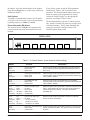
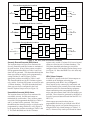
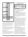
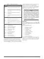
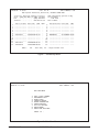
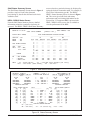
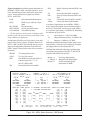
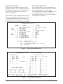
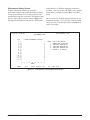
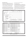
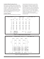
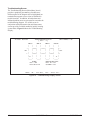
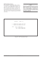
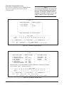
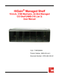
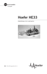
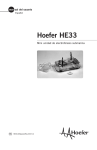
Section 61221051L1-5A
Issue 1, April 2000
CLEI # T1L4FFCC_ _
E220 HFAC HDSL / HDSL2 FUSE Alarm Control Unit
Installation and Maintenance
CONTENTS
1. GENERAL ..................................................................... 1
2. INSTALLATION .......................................................... 2
3. CONNECTIONS ........................................................... 6
4. FACEPLATE FEATURES ........................................... 7
5. CONTROL PORT OPERATION ................................. 7
6. MAINTENANCE ........................................................ 20
7. SPECIFICATIONS ...................................................... 20
8. WARRANTY AND CUSTOMER SERVICE ............ 20
HFAC1
1L
122105
TABLES
Table 1. Compliance Codes ................................................ 1
Table 2. S1 Switch Options ............................................... 3
Table 3. S2 Switch Options ............................................... 4
Table 4. S3 Switch Options ............................................... 4
Table 5. External HTU-C/HTU-R Alarm Options ............ 6
Table 6. HFAC Faceplate Features .................................... 7
Table 7. Screen Abbreviations ........................................... 8
Table 8. E220 HFAC Specifications ................................ 20
61221051L1-5A
ACO
MAJOR
MINOR
SHELF
FIGURES
Figure 1. ADTRAN E220 HFAC ...................................... 1
Figure 2. Configuration and Shelf Address Switches ....... 2
Figure 3. SW3 Location ..................................................... 3
Figure 4. ES, SES, and UAS Monitor Locations ............... 5
Figure 5. HFAC Wire-Wrap Pin-Out Design .................... 6
Figure 6. Control Port Pin Assignments (DCE
Configuration) .................................................... 7
Figure 7. Introductory Menu .............................................. 9
Figure 8. Main Menu Screen ............................................. 9
Figure 9. Shelf Status Summary Screen .......................... 10
Figure 10. Status Summary Screen ................................... 10
Figure 10A. HDSL Status Summary -HRE Screen ......... 11
Figure 11. Shelf Options Setup Screen ............................ 12
Figure 12. Performance Data Screen ............................... 12
Figure 13. Slot Specific Performance Data Screen ......... 13
Figure 14. Alarm Status Summary Screen ...................... 14
Figure 15. Alarm History Screen ..................................... 14
Figure 16. Loopback Status Summary Screen ................. 15
Figure 17. Slot Specific Loopback Options Screen ......... 15
Figure 18. Troubleshooting Display Screen .................... 16
Figure 19. Self-Test Options Screen ................................ 17
Figure 20. Provisioning Screen ........................................ 18
Figure 21. Protection Screen (Main) ................................ 19
Figure 22. Protection Screen (Aux) ................................. 19
PWR
AL
CRITIC
A
L
A
R
M
S
RESS
ADD
ACE
CRAFT
R
S
2
3
2
INTERF
P
0.25 AM
P
0.25 AM
Figure 1. ADTRAN E220 HFAC
1. GENERAL
The ADTRAN E220 HDSL / HDSL2 Fuse/Alarm/
Control (HFAC), P/N 61221051L1, unit is a shelf
controller unit designed for operation in the ADTRAN
E220 HDSL / HDSL2 Central Office (CO) shelf.
Figure 1 is an illustration of the E220 HFAC.
Revision History
Revisions to this practice will be summarized in this
paragraph.
The E220 HFAC provides a common access point to
performance and provisioning information related to
each HDSL / HDSL2 transceiver unit for the central
office (HTU-C and H2TU-C) deployed in the E220
shelf. By addressing the HTU-C or H2TU-C, the HFAC
also provides support for the HDSL / HDSL2 range
extender (HRE and H2R) and the HDSL / HDSL2
transceiver unit for the remote end (HTU-R and H2TU-R).
The shelf supports one shelf controller (HFAC) and up
to 13 HTU-C / H2TU-C cards for the 23-inch shelf or 11
HTU-C / H2TU-C cards for the 19-inch shelf. A
faceplate-mounted DB9 connector provides a VT 100
compatible terminal interface for controlling the
system.
61221051L1-5, Issue 1
Trademarks: Any brand names and product names included in this document are
trademarks, registered trademarks, or trade names of their respective holders.
1
Electrical cable compliance
Table 1 shows the Compliance Codes for HFAC. The
HFAC complies with the requirements covered under
UL 1950 third edition and is intended to be installed
in an enclosure with an Installation Code (IC) of “B”
or “E.”
The HFAC supports the HTU-Cs / H2TU-Cs listed
below.
•
•
•
•
•
•
•
1242024L1
1242002L2
1242002L5
1242002L6
1245001L2
1245001L9
1245011L1
•
•
•
•
•
•
1242002L7
1242029L1
1242029L2
1244001L1
1246001L2
1221001L2
NOTE
This product is intended for installation in
Restricted Access Locations Only. Input
current at maximum load is 1A at -48 VDC.
Maximum output at overcurrent condition is
165 mA at -190 VDC.
The differences in functionality when working with
list-specific HTU-Cs / H2TU-Cs or HREs / H2Rs, if
any, are called out in this practice. Also, the HFAC
has necessary interface software for communications
with the HCOT-CTL (ADTRAN p/n: 1240009L1,
1244051L1, 1221051L1). See appropriate HCOT
practices for installation and maintenance information.
The HFAC collects and presents performance
information for each circuit deployed in the shelf. It
also allows control of all provisioning information for
each circuit. The unit can also be configured to
provide advanced alarm processing features.
Table 1. Compliance Codes
Code Input Output
IC
TC
PC
A
F
C
Configuration
Operation of the HFAC is influenced by three sets of
configuration option switches (see Figures 2 and 3).
2. INSTALLATION
C A U T I O N !
SUBJECT TO ELECTROSTATIC DAMAGE
OR DECREASE IN RELIABILITY.
HANDLING PRECAUTIONS REQUIRED.
After unpacking the unit, inspect it for damage. If
damage is discovered, file a claim with the carrier,
then contact ADTRAN. See Warranty and Customer
Service.
Shelf Address
Two rotary switches (U38 and U39) are provided to
program the shelf’s address. In a system where
several shelves are under the common control of one
ADTRAN E220 HCOT-CTL System Controller, each
individual shelf must be programmed with a unique
shelf address. Addresses range from 00 to 99. In a
system that does not utilize the HCOT-CTL System
Controller, the shelf address is not used. To program
Shelf Address Select Switches
(Default = 00)
Ones Tens
7 8
4 5 6
2 3
Up
4 5 6
7 8
2 3
1234 5678
9 0 1
S1
1234 5678
9 0 1
S2
Faceplate
Figure 2. Configuration and Shelf Address Switches
2
61221051L1-5, Issue 1
61221051L1-5A
the address, select the desired address in the Options
Setup Screen (Figure 11), or set the rotary switches as
indicated in Figure 2.
Unit Options
Two banks of configuration switches (S1, S2 and S3,
see Figure 2 and 3) are used to select advanced alarm
reporting features (see Tables 2, 3 and 4).
Errored Seconds (ES) Alarm
The locations shown in Figure 4 are monitored for
errored seconds and counts are maintained for each
location.
If any of these counts exceed the ES programmed
threshold (see Tables 1 and 2) an alarm will be
generated. This alarm threshold and the alarm type
(minor or major) can be programmed by setting
switches S1 and S2 (Figure 2) to the appropriate
positions, according to Tables 1 and 2.
The alarm thresholds are for the 15-minute registers
only, and the 15-minute ES counts are zeroed at each
15-minute boundary. The ES alarm threshold and
alarm type can also be configured in the Craft
interface Options Setup screen.
REAR VIEW
SW3
Up
Figure 3. SW3 Location and Options
Table 2. S1 Switch Options (arrow indicates default setting)
Switch
Description
Function
S1-1 .................................. Errored Seconds
Down ................................ Minor Alarm
Up (open) ......................... Major Alarm
Selects the type of alarm generated when the errored seconds
(ES) counter exceeds the programmed threshold (see Table 2,
S2-1, S2-2).
S1-2 .................................. Severely Errored Seconds
Down ................................ Minor Alarm
Up (open) ......................... Major Alarm
Selects the type of alarm generated when the severely errored
seconds (SES) counter exceeds the programmed threshold (see
Table 2, SW2-3, SW2-4).
S1-3 .................................. Unavailable Seconds
Down ................................ Major Alarm
Up (open) ......................... Critical Alarm
Selects the type of alarm generated when the unavailable
seconds (UAS) counter exceeds the programmed threshold (see
Table 2, SW2-5, SW2-6).
S1-4 ...........
Down .........
Up (open) ..
Down .........
Up (open) ..
S1-5 .............
Down ............
Down ............
Up (open) .....
Up (open) .....
HFAC Fuse Alarm Type
No Alarm
Minor Alarm
Major Alarm
Critical Alarm
Selects the type of alarm generated in response to an HFAC fuse
failure. Switch SW3 must also be set correctly for this alarm to
function properly (see Table 3). This option is hardwareselectable only.
S1-6 ...........
Down .........
Up (open) ..
Down .........
Up (open) ..
S1-7 .............
Down ............
Down ............
Up ................
Up (open) .....
HTU-C Fuse alarm Type
No Alarm
1 or more: Critical
1: Major, 2-13: Critical
1-5: Major, 6-13: Critical
Selects the type of alarm generated in response to a specific
number of HTU-C fuse failures.
S1-8 .................................. HCOT-CTL Fuse Alarm Type Selects the type of alarm generated in response to an HCOT-CTL
system controller fuse failure. This option can only be selected
Down ................................ Major Alarm
by switch.
Up (open) ......................... Critical Alarm
61221051L1-5A
61221051L1-5, Issue 1
3
Table 3. S2 Switch Options (arrow indicates default setting)
Switch
Description
Function
S2-1 ...........
Down .........
Up (open) ..
Down .........
Up (open) ..
S2-2 .............
Down ............
Down ............
Up (open) .....
Up (open) .....
ES Alarm Threshold
No Alarm
15
30
150
Selects the threshold for generating an ES alarm. Once the number
detected exceeds the threshold, an alarm is generated as
programmed by S1-1. The alarm condition is cleared at the next 15minute boundary.
S2-3 ...........
Down .........
Up (open) ..
Down .........
Up (open) ..
S2-4 .............
Down ............
Down ............
Up ................
Up (open) .....
SES Alarm Threshold
No Alarm
5
15
75
Selects the threshold monitored for generating an SES alarm.
Once the number detected exceeds the threshold, an alarm is
generated as programmed by S1-2. The alarm condition is cleared
at the next 15-minute boundary.
S2-5 ...........
Down .........
Up (open) ..
Down .........
Up (open) ..
S2-6 .............
Down ............
Down ............
Up (open) .....
Up (open) .....
UAS Alarm Threshold
No Alarm
5
15
75
Selects the threshold monitored for generating an UAS alarm.
Once the number detected exceeds the threshold, an alarm is
generated as programmed by S1-3. The alarm condition is cleared
at the next 15-minute boundary.
S2-7 ...........
Down .........
Up (open) ..
Down .........
Up (open) ..
S2-8 .............
Down ............
Down ............
Up ................
Up (open) .....
COMM Link Loss Alarm
No Alarm
Minor
Major
Critical
Selects the type of alarm generated when a loss of communication
between the HFAC controller and an HTU-C occurs. This option is
switch-selectable only.
Table 4. S3 Switch Options (arrow indicates default setting)
NOTE: Only one of the S3 Switches should be in the down position.
Switch
4
Description
Function
S3-1 .................................. HFAC Fuse Alarm Control
Down ................................ Critical
Up ..................................... No Alarm
Selects Critical as the type alarm generated if the HFAC fuse
is blown.
S3-2 .................................. HFAC Fuse Alarm Control
Down ................................ Major
Up ..................................... No Alarm
Selects Major as the type alarm generated if the HFAC fuse
is blown.
S3-3 .................................. HFAC Fuse Alarm Control
Down ................................ Minor
Up ..................................... No Alarm
Selects Minor as the type alarm generated if the HFAC fuse
is blown.
61221051L1-5, Issue 1
61221051L1-5A
Errored Seconds Monitor Locations
HRE
HTU-C
ES
DSX-1
ES
C-1
Loop 1
To
Network
ES
C-2
Loop 2
HTU-R
ES
H-1
ES
H-2
ES
H-3
ES
H-4
Loop 1
ES
R-1
Loop 2
ES
R-2
Severely Errored Seconds Monitor Locations
HRE
HTU-C
SES
DSX-1
To
Network
SES
C-1
SES
C-2
Loop 1
Loop 2
SES
H-4
SES
H-3
To
Customer
HTU-R
SES
H-2
SES
H-1
ES
DS1
Loop 1
SES
R-1
Loop 2
SES
DS1
To
Customer
SES
R-2
Unavailable Seconds Monitor Locations
HRE
HTU-C
UAS
DSX-1
To
Network
UAS
C-1
UAS
C-2
HTU-R
Loop 1
UAS
H-1
UAS
H-2
Loop 1
Loop 2
UAS
H-3
UAS
H-4
Loop 2
UAS
R-1
UAS
R-2
UAS
DS1
To
Customer
Figure 4. ES, SES, and UAS Monitor Locations
Severely Errored Seconds (SES) Alarm
registers only, and the 15-minute UAS errored second
The locations shown in Figure 4 are monitored for
counts are zeroed at each 15-minute boundary. The
Severely Errored Seconds and counts are maintained
UAS alarm threshold and alarm type can also be
for each location. If any of these counts exceed the
configured in the Craft interface Options Setup screen
SES programmed threshold (see Tables 1 and 2) an
(see Figure 11). Note that HDSL2 two wire units only
alarm will be generated. This alarm threshold and the
have Loop 1.
alarm type (minor or major) can be programmed by
HFAC Alarm Outputs
setting switches S1 and S2 (Figure 2) to the
If an HFAC is present in the shelf, alarm outputs are
appropriate positions according to Tables 1 and 2.
available on the backplane wirewrap pins
The alarm thresholds are for the 15-minute registers
corresponding to the HFAC slot (see Figure 5).
only, and the 15-minute SES counts are zeroed at each
These outputs are dry contact relay connections and
15-minute boundary. The SES alarm threshold and
provide normally open, normally closed and common
alarm type can also be configured in the Craft
connection points for alarm monitoring equipment.
interface Options Setup screen (see Figure 11).
Alarm connection points corresponding to critical
Unavailable Seconds (UAS) Alarm
major, and minor alarms (both visible and audible) are
The locations shown in Figure 4 are monitored for
provided. These alarms are generated by the HFAC as
unavailable seconds. Seconds and counts are
a result of processed data collected from the HTU-Cs /
maintained for each location. If any of these counts
H2TU-Cs.
exceed the UAS programmed threshold (see Tables 1
Alarm outputs presented on these pins are
and 2), an alarm will be generated. This alarm
programmable and can be provisioned in the HFAC
threshold and the alarm type (major or critical) can be
Options Setup screen (see Options Setup screen), or
programmed by setting switches S1 or S2 (Figure 2)
using the HFAC dip switch settings (see Tables 1, 2,
to the appropriate positions according to Tables 1 and
and 3). Alarm severity can be provisioned for alarms
2. The alarm thresholds are for the 15-minute
61221051L1-5A
61221051L1-5, Issue 1
5
Critical
Major
Minor
Fault
Locate
VIS NO
26
1
VIS C
27
2
VIS NC
28
3
AUD NO
29
4
AUD C
30
5
AUD NC
31
6
VIS NO
32
7
VIS C
33
8
VIS NC
34
9
AUD NO
35
10
AUD C
36
11
AUD NC
37
12
VIS NO
38
13
VIS C
39
14
VIS NC
40
15
AUD NO
41
16
AUD C
42
17
AUD NC
43
18
44
19
45
20
46
21
T
47
22
R
48
23
49
24
50
25
NO:
NC:
C:
HFAC SLOT
(JP1)
Options Screen
Menu Item No. Function
Description
5 ........................... EXT HTU-C/R Alarms Disables and
enables the alarms
Disabled
resulting from external
Enabled
DSX-1 or DS1
HTU-C Fuse Alarm
An alarm may be generated as a result of an HTU-C
fuse failure. The HFAC controller will sense the
failure and process this alarm event according to
switch settings as defined in Table 2.
3. CONNECTIONS
The HFAC plugs into Slot 0 (labeled HFAC) of the
ADTRAN E220 shelf. Push firmly to ensure the card
seats properly. Connections to the HFAC are made by
wire wrap connections to the backplane-mounted
connector. JP1 is the primary interface connector for
the HFAC. Figure 5 shows the wire-wrap connector
terminal pin assignments.
Remote
ACO
Normallly Open Position
Normally Closed Position
Common
Figure 5. HFAC Wire-Wrap Pin-Out Design
resulting from blown fuses in the HFAC, HTU-C, or
HCOT units, or from communications failure between
any HTU-C and the HFAC. Alarm severity and
threshold value can be provisioned for the errored
second, severely errored second, and unavailable
second parameters.
An option available on the HFAC Option Setup screen
allows external DSX-1 or DS1 alarms to be enabled or
disabled. This option can only be changed in the
HFAC menu (no dip switch option) and the factory
default is disabled (see Table 5).
HFAC Fuse Alarm
An alarm may be generated as a result of an HFAC
fuse failure. For alarm processing to work, two sets of
switches (S1 and S3) must be programmed. See Table
1 and 4. Both switches must be set properly for the
HFAC fuse alarm to operate correctly.
6
Table 5. External HTU-C/HTU-R Alarm Options
(Software-Selectable Only)
(arrow indicates default setting)
Alarms
A set of alarm contacts is provided through backplane
wire-wrap connections (Figure 5). Wiring can be
made to the appropriate pins on JP1 for normally open
or normally closed connections for alarm conditions.
Connection is made to the Common (C) pin and to the
Normally Open (NO) or Normally Closed (NC) pin.
Visible and audible alarm contact connections are
provided for critical, major, and minor alarms. An
audible alarm cutoff function can be initiated by
pressing the ACO push-button on the HFAC, or by
providing closure between the Remote ACO pins on
the JP1 connector. The backplane is labeled with
appropriate markings for the alarm and alarm cutoff
connections.
System Communications
If the HFAC is to be used as part of a larger system
under the control of an ADTRAN E220 HCOT-CTL
system controller, then shelf-to-shelf connections are
required. Two RJ45S jacks, JP6 and JP7, located on
the shelf backplane, provide shelf-to-shelf
communications. A 4- or 8-wire cable with RJ45S
type jacks should be used to supply these
interconnections. The sequence of connections should
be from the RS422 OUT port of the shelf containing
the E220 HCOT-CTL system controller to the RS422
IN port of the next shelf. Follow this procedure to
61221051L1-5, Issue 1
61221051L1-5A
interconnect subsequent shelves. Each shelf controller
should be assigned unique sequential shelf addresses.
No connection should be made to the RS422 in
connector on the shelf containing the E220 HCOT-CTL.
The terminal interface operates at a data rate range of
4.8 kbps to 19.2 kbps. The asynchronous data format
is fixed at eight data bits, no parity, one stop bit. The
supported terminal type is VT 100, or compatible.
4. FACEPLATE FEATURES
Optional terminal parameters should be set as follows:
Table 6 defines the faceplate features of the
HFAC.
5. CONTROL PORT OPERATION
The HFAC provides a faceplate-mounted DB9
connector which supplies an RS232 interface for
connecting to a controlling terminal. Pin assignments
are shown in Figure 6.
1
2
3
4
5
6
7
8
9
DSR
RTS
CTS
TXD (TXD to DTE)
RXD (TXD from DTE)
DTR
SGN GND
•XON/XOFF flow control
•TX carriage return
•Send ACK*
•Linewrap
•Duplex setting
•Asynchronous format
•Cursor
•Display Width
•Display Height
On
<CR> (not <CRLF>)
Off
Off
Full
8 data bits, no parity,
1 stop bit
Off (if possible)
80 columns
24 lines (minimum)
*or any other autonomously-sent character from terminal
Screen Abbreviations
Screen diagram abbreviations used are defined in
Table 7.
Figure 6. Control Port Pin Assignments
(DCE Configuration)
Table 6. HFAC Faceplate Features
HFAC
Indicators
and LEDs
1221051L1
A
L
A
R
M
S
CRITICAL
PWR
MAJOR
ACO
PWR
ALARMS
MINOR
Description
Indicates that power is present to the HFAC card.
Critical (red) ...... Indicates that a critical alarm condition is present.
Major (red) ........ Indicates that a major alarm condition is present.
Minor (yellow) ... Indicates that a minor alarm condition is present.
SHELF ADDRESS
ACO ................. Alarm cut off. Indicates that the audible portion of an
alarm has been terminated.
CRAFT INTERFACE
SHELF
ADDRESS
R
S
2
3
2
0.25 AMP
Button
ACO
Fuse
RS232
61221051L1-5A
The shelf address is indicated using two 7-segment LED displays. The
address is programmed using the switches described in subsection 2 and
tables A and B; or using the Options Setup screen (see Figure 11).
A single momentary push-button provided to operate the alarm cut off
function. When the button is present, the audible portion of an active
alarm is silenced. The condition of the alarm itself is not affected.
This 0.25 -amp fuse is provided to protect the card from power-related
failures. The fuse is a BUSS BMT-0.25, or equivalent. If the fuse opens, a
fuse alarm is generated as described in subsection 2. The fuse has a visual
tripped indicators. When the metal tab (visible through the cover) flips up,
the fuse has opened.
A faceplate-mounted DB9 connector which supplies an RS232 interface
for connection to a controlling terminal. Refer to subsection 5.
61221051L1-5, Issue 1
7
Table 7. Screen Abbreviations
Abbreviations
Description
DSX/DS1
BPV .......... Second in which a bipolar violation occurs.
ES ............ SF: Second in which a BPV or frame bit error
occurs. ESF: Second in which a BPV or CRC
error occurs.
SES .......... Second in which 1544 BPVs or 8 frame bit
................. errors occur.
UAS .......... Second in which there is a loss of signal or loss
of sync.
HDSL Loops
ES ............ Second in which a CRC error occurs.
technical support phone numbers along with serial
numbers, CLEI codes, date of manufacture
information for each active HDSL / HDSL2 system
element, and if the circuit has an installed HDSL /
HDSL2 range extender (HRE / H2R).
NOTE
The command keys valid for each screen are
shown at the bottom of the display. Pressing
keys other than these may cause the HFAC to
adjust to a different speed. If this happens,
the HFAC will not respond to keyboard
commands and may display random
characters. Press the space bar repeatedly
until the screen is re-displayed.
SES .......... Second in which 165 CRC errors occur.
Main Menu
UAS .......... Second in which there is a loss of signal or loss
of sync.
General
From the Introductory Screen, select Main Menu
by typing M. Figure 8 illustrates the Main Menu
Screen.
SF ............. Superframe format.
From the Main Menu select:
ESF .......... Extended superframe format.
1. Shelf Status Summary
2. Performance Data
3. Alarm Status
4. Loopback Control
5. ADTRAN Information
6. Troubleshooting
7. Self-Test Options
8. Provisioning
9. Protection Switching
Selection of 5, ADTRAN Information, presents the
same screen as the Introductory Screen. Description
of other screen selections available from the Main
Menu follow.
B8ZS ........ Binary 8 zero substitution.
AMI ........... Alternate mark inversion.
LBO .......... Line build-out.
NIU ........... T1 network interface unit.
DOM ......... Date of manufacture.
S/N ........... Serial number.
15M .......... Fifteen-minute period.
24H ........... Twenty-four-hour period.
A terminal session is initiated by entering multiple
space bar characters which are used by the HFAC to
determine the speed of the terminal. Once the speed
has been derived, an Introductory Menu is presented as
illustrated in Figure 7. This screen includes ADTRAN
8
61221051L1-5, Issue 1
61221051L1-5A
08/08/70
17:55:57
A D T R A N
SHELF ADDRESS = 00
901 Explorer Boulevard, Huntsville, Alabama 35806-2807
********** Technical Support **********
Voice (888) 873-HDSL or (800) 726-8663
Fax .................. (256) 963-6217
Internet .............. www.adtran.com
1
2
3
4
5
6
7
8
9
10
11
12
13
:
:
:
:
:
:
:
:
:
:
:
:
:
HTU-C Serial#
------------------------------------------------------------------------------A12344321
----------------------------------------------------A11111111
A12345678
PRESS :
CLEI Code
------------------------------------------------------T1LIDPX2AA
------------------------------------T1LIDP02AA
T1L2BUCBAA
“M”
DOM
------------------------01/97
----------------01/97
08/99
HRE?
-
HFAC Information [Version 3.00]
Serial Number :
CLEI Code :
Date of Manf. :
1
2
3
4
5
6
7
8
9
10
11
12
13
:
:
:
:
:
:
:
:
:
:
:
:
:
HTU-R Serial#
------------------------------------------------------------------------------B805A5458
-------------------------------------------------------------------------------
CLEI Code
------------------------------------------------------T1L2CRVBAA
-------------------------------------------------------
DOM
------------------------02/98
-------------------------
- main menu, “R” - range extender info
Figure 7. Introductory Menu
08/08/70
17:57:06
SHELF ADDRESS = 00
HFAC MAIN MENU
1:
2:
3:
4:
5:
6:
7:
8:
9:
SHELF STATUS SUMMARY
PERFORMANCE DATA
ALARM STATUS
LOOPBACK CONTROL
ADTRAN INFORMATION
TROUBLESHOOTING
SELF-TEST OPTIONS
PROVISIONING
PROTECTION SWITCHING
CHOOSE 1-9 :
Figure 8. Main Menu Screen
61221051L1-5A
61221051L1-5, Issue 1
9
screen related to a particular slot may be displayed by
typing the desired slot number and S. For example, to
access Slot 6 information, type 6S. The HDSL /
HDSL2 Status Summary Screen is shown in Figure
10. This screen gives both local and remote
performance and provisioning information for the
selected slot. If a supported HRE is present in the
HDSL / HDSL2 circuit, screen 10A is available to
view the performance of the HRE.
Shelf Status Summary Screen
The Shelf Status Summary Screen shown in Figure 9
provides a top-level look at the alarm and
provisioning of data for the shelf and each circuit
within the shelf.
HDSL / HDSL2 Status Screen
From the Shelf Status Summary Screen, detailed
information related to a particular circuit may be
accessed. The HDSL / HDSL2 Shelf Status Summary
08/08/70
17:59:19
SHELF ADDRESS = 00
SHELF STATUS SUMMARY
ACTIVE SHELF ALARMS
—————————
CRITICAL - YES
MAJOR
- NO
MINOR
- NO
HFAC ALARM THRESHOLD OPTION SETTINGS
——————————————————————————————————————————————————————
ES
SES
UAS
SLOT TYPE THRSHLD
TYPE THRSHLD
TYPE THRSHLD
---- ------------------------------------1: ------------2: ------------3: ------------4: ------------5: ------------6: ------------7:* MAJ
150
MAJ
075
CRIT
075
8: ------------9: ------------10: ------------11: ------------12:* MAJ
150
MAJ
075
CRIT
075
13:* MAJ
150
MAJ
075
CRIT
075
FUSE ALARM SETTINGS
——————————————————
HFAC : CRIT
HTU-C : 1-5 = MAJ,
6-13 = CRIT
LEGEND
——————————————————
NA
= NOT ALARMED
*
= DEFAULT
—
= EMPTY SLOT
PRESS :
[ BYPASS = OFF ]
“O” - change options,
“D” - read HFAC switch defaults (all slots),
nn”S” - slot select (HDSL STATUS),
“M” - main menu :
Figure 9. Shelf Status Summary Screen
08/08/70 18:00:37
LOOP #1 <NETWORK> LOOP #2
--------- HTU-C --------01 dB
01 dB
YES
YES
000/00001
000/00001
000/00000
000/00000
000/00026
000/00025
LOOPBACKS INACTIVE
HTU-C SIGNAL
[X]
9
L[X]
8
O[X]
7
O[X]
6
P[X]
5
[X]
4
1[X]
3
[X]
2
[X]
1
[X]
0
SUMMARY - [ SLOT 7 ]
ELAPSED TIME 00:09:56
<LOSS
<SYNC
<- ES
15M/24H
<- SES 15M/24H
<- UAS 15M/24H
->
->
->
->
->
SHELF ADDRESS = 00
LOOP #1 <CUSTOMER>LOOP #2
--------- HTU-R --------01 dB
01 dB
YES
YES
000/00001
000/00001
000/00000
000/00001
000/00026
000/00025
LOOPBACKS INACTIVE
QUALITY
[X]
L[X]
O[X]
O[X]
P[X]
[X]
2[X]
[X]
[X]
[X]
DSX-1
DS1
———————————————
[X]
9
SF
<- FRAME ->
SF
AMI
<- CODE ->
AMI
EXT
<- LBO
->
0 dB
N/A
<- NIU
->
NO
00000
<- BPV
->
00000
00000
<- ES
->
00000
00000
<- SES
->
00000
00324
<- UAS
->
00302
RED
<- ALARMS ->
RED
SEALING CURRENT PRESENT
“P” - prev scrn,
“M” - main menu,
“Z” - clr current reg,
HTU-R SIGNAL
[X]
L[X]
8
O[X]
7
O[X]
6
P[X]
5
[X]
4
1[X]
3
[X]
2
[X]
1
[X]
0
QUALITY
L[X]
O[X]
O[X]
P[X]
[X]
2[X]
[X]
[X]
[X]
nn”S” - slot:
Figure 10. Status Summary Screen
10
61221051L1-5, Issue 1
61221051L1-5A
Figures 10 and 10A consolidate current information for
the HDSL / HDSL2, DSX-1, and DS1 interfaces. A key
to the information provided is found in the center of the
screen. Arrows indicate the key applies to both the
HTU-C and HTU-R.
LOSS
SYNC
Pulse Attenuation Measurement
HDSL Loop 1 and Loop 2 Sync
Status
ES 15M/24H
Errored Seconds*
SES 15M/24H
Severely Errored Seconds*
UAS 15M/24H Unavailable Seconds*
* The first number is for the current 15-minute period
and the second is the current 24-hour period (Loop 1 and
Loop 2 numbers are displayed).
An indication of Pair Reversal (if present) is given at the
bottom of the first key column. Loopback status for the
HTU-C, HRE, and HTU-R is indicated on these screens.
Status and configuration information for the DS1 and
DSX-1 signals is located in the center of the screen near
the bottom.
FRAME
CODE
LBO
NIU
T1 Framing Format select
T1 Line Code selected
Line Build-Out selected (for DSX-1);
Customer signal of 0, -7.5, -15,
and -22.5 dB (for DS1)
Network Interface Unit enabled?
08/08/70 18:05:00
LOOP #1 <NETWORK> LOOP #2
--------- HRE #1--------00 dB
00 dB
YES
YES
000/00000
000/00001
000/00000
000/00000
001/00001
001/00001
LOOPBACK INACTIVE
HRE#1 NET
[X]
L[X]
O[X]
O[X]
P[X]
[X]
1[X]
[X]
[X]
[X]
BVP
Bipolar Violations detected (DSX-1 and
DS1)
ES
Errored Seconds (DSX-1 and DS1)
SES
Severely Errored Seconds (DSX-1 and
DS1)
UAS
Unavailable Seconds (DSX-1 and DS1)
Alarms
Lists current alarm condition status
A measure of signal quality for each HDSL / HDSL2
loop is displayed in graphic form on the bottom right of
the screen. The measure is from 0 (poor signal quality)
to 9 (excellent signal quality). Guidelines for interpreting
the indicators are given below.
0
Noise margin is ≤ 0 dB (≈ 10-7 BER)
1-8
Margin measurement above 10-7 BER in dB
9
Margin is ≥ 9 dB above 10-7 BER
Predicting performance based upon signal quality varies
with each loop. Generally, a noise margin of 0 or higher
will support a bit error rate of better than 10-7.
ADTRAN has defined the following as guidelines that
correspond to the operation of the HTU-C and HTU-R
faceplate LEDs labeled LP1 and LP2.
Margin < 0
Poor Loop Signal Quality
0 ≤ Margin ≤ 2 Marginal Loop Signal Quality
Margin > 2
Good Loop Signal Quality
(better than 10-9 BER)
SUMMARY - [ SLOT 8 ]
ELAPSED TIME 00:14:17
<LOSS
<SYNC
<- ES
15M/24H
<- SES 15M/24H
<- UAS 15M/24H
->
->
->
->
->
SHELF ADDRESS = 00
LOOP #1 <CUSTOMER>LOOP #2
--------- HRE #1--------01 dB
01 dB
YES
YES
001/00001
001/00001
000/00000
000/00000
006/00006
001/00001
SIGNAL QUALITY N = NETWORK SIDE RECEIVER
HRE#1
9
[X]
C = CUSTOMER SIDE RECEIVER
8
L[X]
7
O[X]
____ LP1 ____ LP1 ____
____
6
O[X]
|HTUC|
|HRE1|
|HRE2|
|HTUR|
5
P[X]
|
|===N|
|C===|
|====|
|
4
[X]
|
|
|
|
|
|
|
|
3
2[X]
|
|===N|
|C===|
|====|
|
2
[X]
|____|
|____|
|____|
|____|
1
[X]
LP2
LP2
0
[X]
“P” - prev scrn,
“M” - main menu,
CUST SIGNAL QUALITY
[X]
9
[X]
L[X]
8
L[X]
O[X]
7
O[X]
O[X]
6
O[X]
P[X]
5
P[X]
[X]
4
[X]
1[X]
3
2[X]
[X]
2
[X]
[X]
1
[X]
[X]
0
[X]
n”H” - element (0H=HTU-C/R, 1H=HRE1, 2H=HRE2)
“Z” - clr current reg,
nn”S” - slot:
Figure 10A. HDSL Status Summary -HRE Screen
61221051L1-5A
61221051L1-5, Issue 1
11
Shelf Controller Options
From the Shelf Status Summary Screen, all shelf
controller options may be reviewed. By typing O at
the Shelf Status Summary Screen, the Shelf Options
Setup Screen may be accessed. This screen is
illustrated in Figure 11.
External DSX-1 or DS1 threshold alarms (ES, SES,
UAS) can be enabled and disabled for a specific slot
by selecting the desired setting from the menu. If
disabled, these alarms will be suppressed, regardless
of how the HTU-C and HTU-R units are provisioned.
OPTIONS SETUP
Performance Data Screen
From the Main Menu, a screen summarizing the 8hour performance data for all slots may be selected.
From the Main Menu, item 2 presents the
Performance Data Screen shown in Figure 12. This
screen graphically summarizes the performance
information for each slot. A key for understanding
the display is also presented.
[SLOT = 8 ]
OPTION #
OPTION
SETTING
--------------------------------------------------------> 1:
HTU-C FUSE ALARM TYPE
---> 1-5 = MAJ, 6-13 = CRIT
SHELF |
2:
SHELF ADDRESS
---> 00
OPTIONS |
3:
SHELF BYPASS
---> OFF
---> 4:
SET DATE/TIME
---> 11/22/99 09:30:31
---> 5:
EXT HTU-C/HTU-R ALARMS
---> DISABLED
|
6:
ES ALARM TYPE
---> MAJOR
SLOT
|
7:
SES ALARM TYPE
---> MAJOR
OPTIONS |
8:
UAS ALARM TYPE
---> CRITICAL
|
9:
ES ALARM THRESHOLD
---> 150
| 10:
SES ALARM THRESHOLD
---> 075
---> 11:
UAS ALARM THRESHOLD
---> 075
PRESS:
“P”
nn”X”
nn”S”
“D”
“M”
-
previous screen
change option n (ex. 4X)
select slot (ex. 11S)
read HFAC switch defaults(this slot only)
main menu
->
<-
Figure 11. Shelf Options Setup Screen
11/23/99
00:15:21
[ SLOT =
PERFORMANCE DATA <VIEW 1 -
8 ]
SHELF ADDRESS = 00
HTU-C DSX-1 RECEIVER>
24 HOUR REGISTERS
15 MINUTE REGISTERS
-------ES------SES------ES----SES------------ES----SES
00000
00000 <---- CURRENT ---->
000
000
-1 : 00000
00000 <---> -1 : 000
000
-17 : -----2 : --------- |
|
-2 : 000
000
-18 : -----3 : --------- |
|
-3 : 000
000
-19 : -----4 : --------- |--PREVIOUS -- |
-4 : -----20 : -----5 : --------- |
|
-5 : -----21 : -----6 : --------- |
|
-6 : -----22 : -----7 : --------- <—
|
-7 : -----23 : ----|
-8 : -----24 : ----|
-9 : -----25 : ----VIEW LOCATION DIAGRAM
|
-10 : -----26 : ----|
-11 : -----27 : ----1-->|H|-3---|H|-----|H|---4-|H|->
|
-12 : -----28 : ----|T|
|R|
|R|
|T|
|
-13 : -----—
29 : ----|U|
|E|
|E|
|U|
|
-14 : -----30 : ----<-- |C|-5---|1|-----|2|---6-|R|<-2
|
-15 : -----31 : ------> -16 : -----32 : ----PRESS : n”V” - view (ex. 4V), “nH” - element (0H=HTU-C/R, 1H=HRE1, 2H=HRE2),
nn”S” - slot (ex. 3S), “M” - main menu,
“P” - prev. screen :
Figure 12. Performance Data Screen
12
61221051L1-5, Issue 1
61221051L1-5A
Performance History Screen
Detailed information concerning 15-minute
performance history and 24-hour performance history
for any given slot may be viewed by typing the slot
number and S from the slot specific Performance Data
Screen. The resulting screen is shown in Figure 13,
Slot Specific Performance Data Screen. Performance
11/22/99
information for six different monitored locations is
available. Also, for circuits with HREs, more detailed
information is available by typing 1H to view HRE
points.
An on-screen view location diagram indicates the six
monitored locations. Seven previous 24-hour periods
and 32 previous 15-minute periods are maintained for
each view location.
09:35:05
SHELF ADDRESS = 00
PERFORMANCE DATA
SLOT
1:
2:
3:
4:
5:
6:
7:
8:
9:
10:
11:
12:
13:
8 HOUR PERFORMANCE HISTORY
[
[*
[*
[*
[*
[
[*
[*
[*
[*
[*
[*
[*
0
PRESS :
]
]
]
]
]
]
]
]
]
]
]
]
]
-1
-2
nn”S”
-3
-4 -5
HOURS
-6
-7
SPACE
E
S
U
*
=
=
=
=
=
=
HTU-C NOT PRESENT
ERROR FREE 15 MIN REG
REGISTER CONTAINS ES
REGISTER CONTAINS SES
REGISTER CONTAINS UAS
PERIOD < 15 MINUTES
-8
- select slot(ex. 5S),
“M” - main menu :
Figure 13. Slot Specific Performance Data Screen
61221051L1-5A
61221051L1-5, Issue 1
13
Alarm Status Screen
Selection of item 3 from the Main Menu presents the
Alarm Status Screen, Figure 14. This screen is a
composite display of all current alarms for each of the
13 slots. Alarm types are indicated by the number 1
for Critical, 2 for Major, and 3 for Minor alarms.
A capital A indicates the alarm is current while a
trailing * indicates the alarm cutoff has been exercised.
ES or SES indicates the programmed threshold has
been exceeded, resulting in an alarm. The position of
the alarm indicator codes in the screen matrix indicates
11/23/99
00:16:44
DEFAULT ALARM TRIGGERS
---------------------CRIT: 6-13 HTU-C FUSES
UAS THRESHOLD
HCOT-CTL FUSE
COMM LINK LOSS
HFAC FUSE
MIN:
1-5 HTU-C FUSES
ES THRESHOLD
SES THRESHOLD
NONE
PRESS :
Alarm History Screen
The Alarm History Summary Screen (Figure 15) can
be accessed from the Alarm Status Screen by pressing
H. This screen provides a time and date stamp for up
to 100 alarm events. These events include alarm
initiation and alarm clear. For convenience, a user
marker can be invoked by pressing X. This produces
a highly visible marking point so that subsequent
alarm events can be easily distinguished from older
ones.
ALARM STATUS
ACTIVE SHELF ALARMS
------------------CRITICAL - YES
MAJOR
- NO
MINOR
- NO
MAJ:
both the alarm location and slot number.
“C”
SHELF ADDRESS = 00
B/ HTUC [ HTUC ] [ HRE1 ] [ HRE2 ] HTUR
SLOT UAS FUS COM SIG LP1 LP2 LP1 LP2 LP1 LP2 SIG
--------------------- --------- --------- --------- ---1: --- --- --- ---- ---- ---- ---- ---- ---- ---- ---2: --- --- --- ---- ---- ---- ---- ---- ---- ---- ---3: --- --- --- ---- ---- ---- ---- ---- ---- ---- ---4: --- --- --- ---- ---- ---- ---- ---- ---- ---- ---5: 1A --- --- --- ---- ---- ---- ---- ---- ---- ---6: --- --- --- ---- ---- ---- ---- ---- ---- ---- ---7: --- --- 1C ---- ---- ---- ---- ---- ---- ---- ---8: --- --- --- ---- ---- ---- ---- ---- ---- ---- ---9: 1A --- --- ---- ---- ---- ---- ---- ---- ---- ---10: 1A --- --- ---- ---- ---- ---- ---- ---- ---- ---11: --- --- --- ---- ---- ---- ---- ---- ---- ---- ---12: 1A --- --- ---- ---- ---- ---- ---- ---- ---- ---13: 1A --- --- ---- ---- ---- ---- ---- ---- ---- ---1 = CRIT, 2 = MAJ, 3 = MIN,
A = UAS OR FUSE ALARM,
B = BER ALARM ON PROTECTED CIRCUIT,
C = COMM ALARM,
E/S = ES/SES THRESHOLD ALARM,
* = ALARM CUTOFF (ACO)
- alarm cutoff,
“H” - alarm history,
“M”
- main menu
Figure 14. Alarm Status Summary Screen
08/08/70 17:51:59 CRITICAL -UAS THRESHOLD CROSSING AT HTU-R LP1, SLOT 10.
08/08/70 17:51:59 CRITICAL -UAS THRESHOLD CROSSING AT HTU-R LP2, SLOT 10.
08/08/70 17:52:09 *CLEARED* -UAS THRESHOLD CROSSING AT HTU-C LP1, SLOT 5.
08/08/70 17:52:09 *CLEARED* -UAS THRESHOLD CROSSING AT HTU-C LP2, SLOT 5.
08/08/70 17:52:34 *CLEARED* -UAS THRESHOLD CROSSING AT HTU-C LP1, SLOT 9.
08/08/70 17:52:34 *CLEARED* -UAS THRESHOLD CROSSING AT HTU-C LP2, SLOT 9.
08/08/70 17:52:36 *CLEARED* -UAS THRESHOLD CROSSING AT HTU-C LP1, SLOT 10.
08/08/70 17:52:36 *CLEARED* -UAS THRESHOLD CROSSING AT HTU-C LP2, SLOT 10.
08/08/70 17:52:36 *CLEARED* -UAS THRESHOLD CROSSING AT HTU-R LP1, SLOT 10.
08/08/70 17:52:36 *CLEARED* -UAS THRESHOLD CROSSING AT HTU-R LP2, SLOT 10.
08/08/70 17:52:41 *CLEARED* -LOSS OF COMMUNICATION WITH SLOT 12.
08/08/70 17:52:42 CRITICAL -LOSS OF COMMUNICATION WITH SLOT 12.
08/08/70 17:52:43 *CLEARED* -LOSS OF COMMUNICATION WITH SLOT 12.
08/08/70 17:54:00 CRITICAL -UAS THRESHOLD CROSSING AT HTU-C LP1, SLOT 12.
08/08/70 17:54:00 CRITICAL -UAS THRESHOLD CROSSING AT HTU-C LP2, SLOT 12.
08/08/70 17:55:04 *CLEARED* -UAS THRESHOLD CROSSING AT HTU-C LP1, SLOT 7.
08/08/70 17:55:04 *CLEARED* -UAS THRESHOLD CROSSING AT HTU-C LP2, SLOT 7.
08/08/70 17:55:05 CRITICAL -UAS THRESHOLD CROSSING AT HTU-C LP2, SLOT 7.
08/08/70 17:55:07 CRITICAL -LOSS OF COMMUNICATION WITH SLOT 7.
08/08/70 17:55:07 *CLEARED* -UAS THRESHOLD CROSSING AT HTU-C LP2, SLOT 7.
---------------------------------------------------------------------------PRESS:
|
ALARM HISTORY PAGE 3 OF 5
1 TO 5 - Select Page, “X” - Set Marker
|
11/23/99 00:18:37
“P” - Prev Screen, “M” - Main Menu
|
SHELF ADDRESS = 00
Figure 15. Alarm History Screen
14
61221051L1-5, Issue 1
61221051L1-5A
Loopback Status Summary Screen
Item selection 4, Loopback Control, from the Main
Menu displays the loopback status information for all
of the HTU-C, HRE, and HTU-R units monitored by
the HFAC. Loopback Status (On, Off, or Not
available) is presented for loopbacks to both the
network and the customer at both the HTU-C, HRE,
and HTU-R. Figure 16 illustrates the Loopback
Status Summary Screen.
Loopback Status Summary Screen, you will be
presented with a slot-specific Loopback Options
Screen (Figure 17). Multiple loopbacks can be
initiated for each circuit. This screen graphically
depicts the loopback activated by showing through
reverse video, the path of the loopback and the
locations it loops to. Also, the status indication
changes from inactive to active. The initiation of a
loopback is accomplished by pressing the
corresponding number of the loopback desired,
followed by an L.
Loopback Options
By pressing a slot number followed by an S from the
11/23/99
00:19:57
HTU-C
<--->
NET
CUST
----------------OFF
OFF
OFF
OFF
OFF
OFF
OFF
OFF
----OFF
OFF
OFF
OFF
OFF
OFF
OFF
OFF
OFF
OFF
OFF
OFF
OFF
OFF
SLOT#
----1 :
2 :
3 :
4 :
5 :
6 :
7 :
8 :
9 :
10 :
11 :
12 :
13 :
ON
OFF
xxxx
----
LOOPBACK STATUS
=
=
=
=
HRE1
<-NET
------xxxx
xxxx
OFF
xxxx
---xxxx
OFF
xxxx
xxxx
xxxx
xxxx
xxxx
SHELF ADDRESS = 00
HRE2
<-NET
------xxxx
xxxx
xxxx
xxxx
---xxxx
OFF
xxxx
xxxx
xxxx
xxxx
xxxx
LOOPBACK ON
LOOPBACK OFF
NOT AVAILABLE
EMPTY SLOT
HTU-R
<--->
NET
CUST
------------------OFF
OFF
OFF
OFF
OFF
OFF
OFF
OFF
------OFF
OFF
OFF
OFF
OFF
OFF
OFF
OFF
OFF
OFF
OFF
OFF
OFF
OFF
PRESS
“nnS”
“M”
- Slot Select,
- Main Menu :
Figure 16. Loopback Status Summary Screen
11/23/99
00:21:48
LOOPBACK OPTIONS
[ SLOT = 8
]
SHELF ADDRESS = 00
_____
_____
_____
_____
|HTU-C|
|HRE 1|
|HRE 2|
|HTU-R|
|
|
|
|
|
|
|
|
|
| LP1 |
| LP1 |
| LP1 |
|
—>|
|<===>|
|<===>|
|<===>|<--, |<—|
|
|
|
|
|
|
| |
NET |
|
|
|
|
|
|
| | CUST
|
| LP2 |
|LP2 |
| LP2 |
| |
<—|
|<===>|
|<===>|
|<===>|<--, |—>
|
|
|
|
|
|
|
|
|
|
|
|
|
|
|
|
|_____|
|_____|
|_____|
|_____|
1)
2)
3)
4)
5)
6)
Press
“nL”
“P”
LOOPBACK
LOOPBACK
LOOPBACK
LOOPBACK
LOOPBACK
LOOPBACK
-
TO
TO
TO
TO
TO
TO
NETWORK
CUSTOMER
NETWORK
CUSTOMER
NETWORK
NETWORK
AT
AT
AT
AT
AT
AT
HTU-C
HTU-C
HTU-R
HTU-R
HRE1
HRE2
Toggle Loopback(ex. 3L),
Previous Screen,
“M” -
=
=
=
=
=
=
UNAVAILABLE
UNAVAILABLE
ACTIVE
UNAVAILABLE
UNAVAILABLE
UNAVAILABLE
“nnS” - Select Slot,
Main Menu :
Figure 17. Loopback Options Screen
61221051L1-5A
61221051L1-5, Issue 1
15
Troubleshooting Screen
The Troubleshooting Screen (Main Menu, Item 6)
provides a graphical presentation of trouble areas.
Different parts of the diagram will be highlighted (on
terminals that support reverse video) to indicate the
trouble locations. In addition, in-band alarms and
indicated problem areas are presented in text under the
troubleshooting diagram. Use of this screen in
conjunction with performance data and alarm status
screens provides a reliable method of quickly locating
system faults. Figure 18 shows the Troubleshooting
Display.
11/23/99
00:24:05
TROUBLESHOOTING DISPLAY
SHELF ADDRESS = 00
[ SLOT = 8 ]
_____
_____
_____
_____
|HTU-C|
|HRE 1|
|HRE 2|
|HTU-R|
|
|
|
|
|
|
|
|
|
|
|
|
|
|
|
|
—>|
|<===>|
|<===>|
|<===>|
|<—|
|
|
|
|
|
|
|
NET |
|
|
|
|
|
|
| CUST
|
|
|
|
|
|
|
|
<—|
|<===>|
|<===>|
|<===>|
|—>
|
|
|
|
|
|
|
|
| T1 |
|
|
|
|
| T1 |
|_____|
|_____|
|_____|
|_____|
ALARMS:
HTU-C RED
BLUE ON DS1 RX
PRESS:
“M” —
main menu,
PROBLEM INDICATED:
DSX-1 RX LOSS
CUSTOMER LOSS
“nnS” — select slot :
Figure 18. Troubleshooting Display Screen
16
61221051L1-5, Issue 1
61221051L1-5A
Self-Test Options Screen
By selecting item 7 from the Main Menu, the SelfTest Options Screen (Figure 19) is presented. From
this screen, a self-test for the HTU-C, HTU-R, and
HFAC controller can be initiated. To initiate a selftest, press the desired test number followed by a T.
Upon completion of the test, results will be presented.
These tests are useful in diagnosing suspect hardware
and circuits.
11/23/99
NOTE
Momentary communications loss between the
HFAC and HTU-C units will occur when the
HFAC is first plugged in, or when HFAC selftest is executed. If HFAC communications
alarms are not disabled, a momentary alarm
may also be generated.
00:26:44
SHELF ADDRESS = 00
SELF-TEST
1.
2.
[ SLOT = 8
]
INITIATE HTU-C AND HTU-R SELF-TESTS
INITIATE HFAC CONTROLLER SELF-TEST
Press :
“nnS”
“nT”
“M”
to select slot
to select desired test
to return to Main Menu :
Figure 19. Self-Test Options Screen
61221051L1-5A
61221051L1-5, Issue 1
17
Provisioning Summary Screen
Selection of item 8 from the Main Menu supplies
provisioning information on individual circuits being
accessed by the HFAC. Figure 20 is a slot-specific
provisioning screen showing the provision option
item, current settings, and hardware settings for that
particular circuit. A key at the bottom of the screen
describes the options associated with this screen.
Menu item 7 provides a means of provisioning
specific HTU-C units, from the HFAC, to enable or
disable various HTU-C alarms. This option is
different from the Disable Alarms option on the
HFAC Options Setup screen. This option sets the
selected HTU-C to enable or disable the alarms
presented on the HTU-C edge connector pins 20 and
21 (closure between pins) and edge connector pin 1
(closure to ground).
The Enable All selection permits alarms to be
presented on the aforementioned edge connector pins
due to faults at any of the HDSL / HDSL2 loop, DSX1, or DS1 locations. The Disable All disables all
alarms due to external faults or faults within the
HDSL / HDSL2 equipment or loops.
The Disable EXT selection allows only alarms caused
by faults in the HDSL / HDSL2 equipment or HDSL /
HDSL2 loops and suppresses alarms caused by
external DSX-1 or DS1 faults.
NOTE
ADTRAN 220/E220 H2TU-Cs support an
EXTERNAL LBO option for use in legacy
220 ORB shelves. The ADTRAN E220 shelf
does not require the EXTERNAL LBO option.
The E220 HFAC will not allow the selection
of the EXTERNAL LBO setting when
initiated through the HFAC terminal screen.
It should be noted that the HFAC will not
automatically override an EXTERNAL LBO
setting.
11/23/99 00:28:34
PROVISIONING
[ SLOT = 8 ]
SHELF ADDRESS = 00
___________________________________________________ ______________________
|
|
|
|
PROVISIONS
CURRENT SETTINGS |
HARDWARE SETTINGS |
|
-------------------------------------- |
----------------- |
|
1. DSX-1 LINE BUILDOUT =
399-533 FEET
|
399-533 FEET
|
|
2. DSX-1/DS1 LINE CODE =
B8ZS
|
B8ZS
|
|
3. DSX-1/DS1 FRAMING
=
ESF
|
ESF
|
|
4. LOOPBACK TIMEOUT
=
NONE
|
NONE
|
|
5. DS1 OUTPUT LEVEL
=
-15 dB
|
-15 dB
|
|
6. NIU LOOPBACK
=
DISABLED
|
DISABLED
|
|
7. DS0 BLOCKING
|
|
|
|
|
|
00000000 00000000 00000000
|
|
|
CHANNELS
1
24
|
|
|
“X” BLOCKS THE CHANNEL.
|
|
|___________________________________________________|______________________|
Press :
“nP”
“H”
“I”
“nnS”
—
—
—
—
to change corresponding provision (ex. 5P)
to copy hardware settings to current settings
to implement and save current setting changes
select slot,
“M”
— main menu
->
<-
Figure 20. Provisioning Screen
18
61221051L1-5, Issue 1
61221051L1-5A
Protection Configuration Screen
The protection configuration screens (Figure 21 and
22) provides status and control details for fault
protected circuits.
11/23/99
NOTE
The screens provided below are typical and
may vary slightly depending on the hardware
installed. For Instance, if HDSL2 H2TU-C
equipment is installed, certain screens will
change to indicate only 1 loop present.
00:32:51
PROTECTION CONFIGURATION
SHELF ADDRESS = 00
[ SLOT 2 ]
________________________________________________
|
PROTECTION OPTIONS
CURRENT SETTINGS
|
|
----------------------------------------|
|
1. BER THRESHOLD
= 1E-7
|
|
2. BER INTERVAL
= 15 MINS
|
|
|
|
|
|
|
|
|
|
|
|________________________________________________|
MAIN CARD CAN ONLY SET THE BER OPTIONS.
-------------------------------- SHELF STATUS ------------------------------|
SLOT -> 01 02 03 04 05 06 07 08 09 10 11 12 13
|
|
STATUS ->
^^---- ** **
** ** ** ** ** ** **
|
|_____________________________________________________________________________|
^^—— = MAIN ACTIVE
——^^ = AUX ACTIVE
** = STANDARD HTU-C
Press:
“nnS” - select slot,
“nP” - select option,
“M” - main menu, “I” - implement and save current changes :
Figure 21. Protection Screen (Main)
11/23/99
00:29:33
PROTECTION CONFIGURATION
SHELF ADDRESS = 00
[ SLOT 3 ]
_____________________________________________________________________________
|
PROTECTION OPTIONS
CURRENT SETTINGS
|
SWITCHOVER HISTORY
|
|
----------------------------------------|
---------------------|
|
1. PROTECTION MODE
= AUTO
|
SWITCHOVERS -> 00
|
|
2. MINIMUM HOLDIN TIME
= 01
MIN(S)
|
REVERSIONS -> 00
|
|
3. BER THRESHOLD
= 1E-7
|
FAILURES
-> 00
|
|
4. BER INTERVAL
= 15
MINS
|
LOCKOUTS
-> 00
|
|
5. LOCKIN HOURS
= 12
HR(S)
|
|
|
6. SWITCH TO AUX LIMIT
= 09
(1-9)
|
|
|
7. LOCKIN CHECK INTERVAL = 20
MIN(S)
|
|
|________________________________________________|____________________________|
LOCKIN OPTIONS: IF 09 SWITCHOVERS OCCUR IN 20 MINUTES, LOCKIN FOR 12 HOURS.
SYSTEM CURRENT STATUS : NORMAL OPERATION
------------------------------------ SHELF STATUS --------------------------|
SLOT -> 01 02 03 04 05 06 07 08 09 10 11 12 13
|
|
STATUS ->
^^---- ** **
** ** ** ** ** ** **
|
|_____________________________________________________________________________|
^^—— = MAIN ACTIVE
——^^ = AUX ACTIVE
** = STANDARD HTU-C
Press:
“nnS” - select slot,
“nP” - select option,
“M” - main menu, “I” - implement and save current changes :
Figure 22. Protection Screen (Aux)
61221051L1-5A
61221051L1-5, Issue 1
19
6. MAINTENANCE
The ADTRAN E220 HFAC requires no routine
maintenance to operate properly.
ADTRAN recommends that major repairs on the
shelf not be performed in the field. Repair services
may be obtained by returning defective units to
ADTRAN.
Contact Customer and Product Service (CAPS) prior
to returning equipment to ADTRAN.
7. SPECIFICATIONS
Table 8 lists E220 HFAC specifications.
Table 8. E220 HFAC Specifications
Power
-48 VDC @ 60 mA (maximum)
Physical
Dimensions: ............. 5.6" high x 1.25" wide x 10.1" deep
Weight: ..................... < 1 pound
Temperature
Operating: ................ -40° C to +70° C
Storage: .................... -40° C to +85° C
Part Number
ADTRAN E220
Shelf Plug in,
Single slot ................. 1221051L1
8. WARRANTY AND CUSTOMER SERVICE
ADTRAN will replace or repair this product within 10
years from the date of shipment if it does not meet its
published specifications or fails while in service
(see ADTRAN Carrier Network Equipment
Warranty, Repair, and Return Policy and Procedure,
document 60000087-10A).
For service, CAPS requests, or further information,
contact one of the following numbers:
Part Number
1221051L1
ADTRAN Sales
Pricing/Availability
(800) 827-0807
ADTRAN Technical Support
Presales Applications/Postsales Technical Assistance
(888) 4-ADTRAN
Standard hours: Monday-Friday, 7 a.m. - 7 p.m. CST
Emergency hours: 7 days/week, 24 hours/day
ADTRAN Repair/CAPS
Return for Repair/Upgrade
(256) 963-8722
Repair and Return Address
ADTRAN, Inc.
CAPS
901 Explorer Boulevard
Huntsville, Alabama 35806-2807
20
61221051L1-5, Issue 1
61221051L1-5A