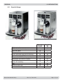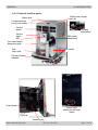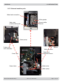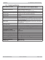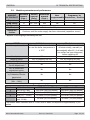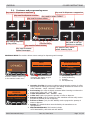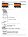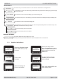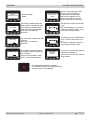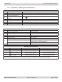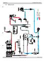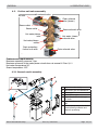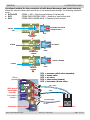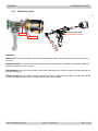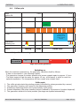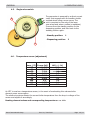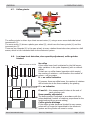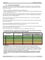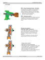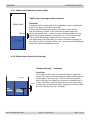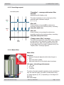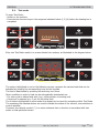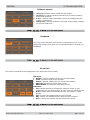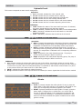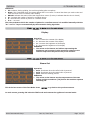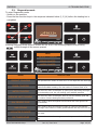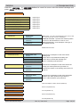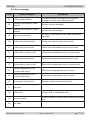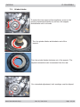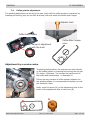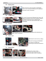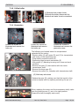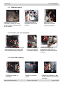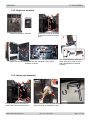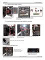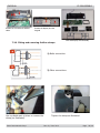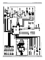
1
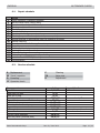
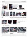
Coffee Machine
Service
Service
Service
Exprelia Series
Se r v ic e Manual
Service
Table of contents
Page
1.
Introduction
1.1.
Documentation required
1
1.2.
Tools and equipment required
1
Table of contents
Page
4.7.
Coffee grinder
4.8.
Low bean level detection, dose quantity adjustment,
coffee grinder blocked
7
8
Dose self-learning (SAS)
9
1.3.
Material
1
4.9.
1.4.
Safety warnings
1
4.10.
SBS
10
1.5
Exprelia Range
2
4.11.
Water level detection (water tank)
11
Water level detection (drip tray)
11
1.6.1.
External machine parts
3
4.12.
1.6.2.
Internal machine parts
4
4.13.
Descaling request
12
4.14.
Water filter
12
2.
Technical specifications
2.1.
Technical specifications
1
5.
Troubleshooting
2.2.
Machine parameters and performance
2
5.1.
Test mode
1
5.2.
Diagnostics mode
5
5.3
Error messages
7
3.
User instructions
3.1.
Customer and programming menu
1
3.2.
Machine indications
3
6.
Standard checks
3.3.
Operation, cleaning and maintenance
5
6.1.
Repair schedule
1
6.2.
Service schedule
1
6.3.
Final test
2
4.
Operating logic
4.1.
Water circuit
1
4.2.
Frother unit valve assembly
2
7.
Disassembly
4.2.1
General carafe assembly
2
7.1.
Outer elements
1
4.3.
Multi-way valve
4
7.2.
Coffee grinder
1
4.4.
Coffee cycle
5
7.3.
Grinder blades
2
4.5.
Single microswitch
6
7.4.
Coffee grinder adjustment
3
4.6
Temperature sensor
6
7.5.
Steam pump
4
All rights reserved. No part of this publication may be reproduced, stored in a
retrieval system or transmitted, in any form or by any means, electronic, mechanical,
photocopying, or otherwise without the prior permission of Saeco.
Published by Saeco International Group
Subject to modification
© Copyright
EN 4219 400 00006
2010-June-01
Table of contents
Page
7.6.
Coffee pump
4
7.7.
Turbine
4
7.8.
Power card
4
7.9.
Steam boiler
4
7.10
Coffee boiler
5
7.11
Gearmotor:
5
7.12.
Multi-way valve
6
7.13
Frother unit valve assembly
6
7.14
Door tube coupling
6
7.15
Dispenser assembly
7
7.16
Steam pipe assembly
7
7.17
General carafe card assembly
8
7.18
Teflon pipe support and carafe attachment assembly
7.19
CPU and display card
8
7.20.
Fitting and removing Oetiker clamps
8
8.
Notes
9.
Water circuit diagram
10
Electrical diagram
Saeco International Group
Rev. 00 /June 2010
EXPRELIA
CHAPTER 1
INTRODUCTION
Saeco International Group
Rev. 00 / June 2010
EXPRELIA
EXPRELIA
1.1
01 INTRODUCTION
Documentation required
The following documentation is needed for repair procedures:
•
•
Instruction booklet for specific model
Technical documentation for specific model (diagrams, exploded drawings)
1.2
Tools and equipment required
As well as the standard equipment, the following is required:
Qty.
1
1
1
1
1
Description
Screwdriver
Pliers for Oetiker clamps
CC -A - Vdc tester
Digital thermometer
SSC (Saeco Service Center)
1.3
Scale limit > 150°C
Programmer
(for programming and diagnostics mode)
Material
Description
Thermal paste
Descaler
Grease solvent
Silicone grease
1.4
Notes
Torx T 8 - T 10 - T 20
Notes
Heating element > 200°C
Saeco descaler
Personal choice
Safe to use with food
Safety warnings
We recommend you consult the technical manual of the machine before performing any
maintenance work.
Observe all applicable standards relating to the repair of electrical appliances.
Always disconnect the power plug from the mains before beginning repair work.
Simply turning off the main machine power switch is not an adequate safety precaution.
This domestic appliance is rated as insulation class I.
On completion of the repair work, insulation and dielectric rigidity tests must be performed.
Saeco International Group
Rev. 00 / June 2010
Page 01 / 04
EXPRELIA
1.5.
01 INTRODUCTION
Exprelia Range
Display interface
With satin-finished steel parts
With ABS parts
Milk carafe
Clean (automatic milk circuit washing)
Automatic dosing (SAS)
Dispensed coffee memory capacity
Dispensed milk memory capacity
Automatic shutdown
(after 60' inactivity)
SBS
Ground coffee well
Automatic descaling cycle
Saeco International Group
Rev. 00 / June 2010
Exprelia
CLASS
X
Exprelia
SS
X
X
X
X
X
X
X
X
X
X
X
X
X
X
X
X
X
X
X
X
X
Page 02 / 04
EXPRELIA
01 INTRODUCTION
1.6.1 External machine parts
Coffee bean hopper
with lid
Water tank
Compartment for
pre-ground coffee
Control
panel
Grinding
adjustment
Service
hatch
Milk carafe
attachment
SBS
Hot water/steam
dispensing pipe
Drip
tray+grille
Milk carafe
Full tray floating
indicator
Dreg drawer
Power cable
connector and main
switch
Drip tray
Brewing unit
Saeco International Group
Rev. 00 / June 2010
Page 03 / 04
EXPRELIA
01 INTRODUCTION
1.6.2 Internal machine parts
Water tank connection
Coffee grinder
Ground coffee
channel
Water tank
present/missing tab
Steam pump
Frother unit
valve assembly
Turbine
Multi-way valve
Water level
capacitive sensor
Power card
Coffee boiler
Steam boiler
Water pump
Saeco International Group
Rev. 00 / June 2010
Page 04 / 04
CHAPTER 2
TECHNICAL SPECIFICATIONS
Saeco International Group
Rev. 00 / June 2010
EXPRELIA
EXPRELIA
2.1.
02 TECHNICAL SPECIFICATIONS
Technical specifications
Power supply and output:
240 V~ 50 Hz 1400 W - 230 V~ 50/60 Hz 1400 W 120 V~ 60 Hz 1500 W - 100 V~ 50/60 Hz 1300 W
Temperature monitoring:
Variable resistance sensors (NTC)
transmits the value to the electronic card
2 manual reset or one-shot thermostats (175°C)
(230/120 V~) 1300 W – (100 V~) 1100W
for coffee, hot water and steam dispensing
Safety system:
Coffee heat exchanger output:
Stainless steel
Steam heat exchanger output:
Stainless steel
Gearmotor:
Coffee pump
Steam pump
Overpressure valve:
(multi-way valve)
Water filter:
Coffee grinder:
Automatic dosage
Power consumption:
Consumption in Standby
Dimensions: W x H x D in mm:
Weight:
Water tank capacity:
Coffee bean hopper capacity
Dreg drawer capacity
Heat exchanger capacity:
Water circuit filling time:
Heating time:
Dispensing temperature:
Grinding time:
Saeco International Group
As above
2 rotation directions; power supply 24VC
Ulka Type EP5/S GW approx. 13-15 bar with reciprocating
piston and thermal switch 120°C 48 W, 230V, 50 Hz, 120V,
60Hz 100V, 50/60 Hz
Ulka MF with reciprocating piston 230V, 50 Hz, 120V, 60Hz
100V, 50/60 Hz
Opening at approx. 17-23 bar
In tank
Direct current motor with flat ceramic grinder blades
Dose adjustment controlled by the electronic system
During heating phase- approx. 5.6 A
<1W
245x360x420
14 kg
1.5 l.
300 g. of coffee beans
11
Approx. 10 cc
Approx. 15 sec Max. on first filling cycle
Approx. 45 sec.
Approx. 84°± 4°
Approx. 8-10 sec.
Rev. 00 / June 2010
Page 01 / 03
EXPRELIA
2.2.
02 TECHNICAL SPECIFICATIONS
Machine parameters and performance
AMOUNT
OF PRODUCT
Espresso
Long coffee
Pre-ground
Hot water
Steam for
frother
Minimum
Default Maximum
User
Programm. by
amount
amount
amount
programmable Production / Service
(Puls.)
(Puls.)
(Puls.)
50
130 - 170 *
600
Yes
No
70
200 - 230 *
600
Yes
No
Yes
Continues for 400 pulses
Continues until the water supply has been exhausted (capacitive sensor)
* Depends on the language selected by the user
RINSE
When performed
Initial rinse
When the machine is switched
on and the boiler temperature is
≤ 50°C
No. of pulses
Stopping option
User disable option
Disabling by Production/
Service department
No. of pulses user
adjustment option
No. of pulses adjustable
by Production/Service
department
Pulse range
(Min. – Max.)
130
Yes, by pressing any key
Yes
Final rinse
When the machine is switched
off electronically, manually or
automatically after 60', if at least
one coffee has been dispensed,
before switching off
100
Yes, by pressing any key
No
No
No
No
No
No
No
No
No
Descaling cycle frequency
Hardness
Water hardness
Without water filter
With water filter
1
Soft (up to 7°dH)
240 litres (480,000 pulses)
480 litres (960,000 pulses)
2
Medium (7° - 14°dH)
120 litres (240,000 pulses)
240 litres (480,000 pulses)
3
Hard (15° - 21°dH)
60 litres (120,000 pulses)
120 litres (240,000 pulses)
4
Very hard
30 litres (60,000 pulses)
60 litres (120,000 pulses)
(over 21°dH)
The default water hardness level is 3. Each litre of water corresponds to approximately 2,000
pulses
Saeco International Group
Rev. 00 / June 2010
Page 02 / 03
EXPRELIA
02 TECHNICAL SPECIFICATIONS
DREG DRAWER
Time-out for dreg drawer
Description and values
5 sec.
Warning to empty dreg drawer after
Yes, after 12 lots of dregs
Shutdown alarm to empty dreg drawer after
(double coffee as last product dispensed)
15 lots of dregs
(16 lots of dregs)
Reset dreg counter
The dreg drawer must be emptied only
when prompted by the machine ensuring
the machine is switched on and removing
the drawer for more than 5 seconds.
STANDBY
Inlet time (min. – max.)
Inlet time (default)
Inlet time programmed by user
Inlet time programmed by Production/
Service
Boiler temperature during Standby
Cup heater during Standby
Timer and Standby
Description and values
15 minutes - 180 minutes
60 minutes
Yes
Yes
Boiler OFF
Cup heater OFF
Yes **
** The machine switches on at the TimerOn (Timer) value and switches off when the
“Standby time” (Delay – Time) has elapsed
WATER TANK
Water reserve (pulses) with water filter
Water reserve (pulses) with no water filter
Water reserve modifiable by Production/Service
departments
"Fill tank" alarm
"No tray" alarm
Water mains
Saeco International Group
Rev. 00 / June 2010
Description
200
200
No
Yes
No
No
Page 03 / 03
CHAPTER 3
USER INSTRUCTIONS
Saeco International Group
Rev. 00 / June 2010
EXPRELIA
EXPRELIA
3.1.
03 USER INSTRUCTIONS
Customer and programming menu
Key used to dispense an espresso
Key used to dispense a cappuccino
Key used to dispense a coffee
Key used to select "MENU"
Key used to select aroma
MENU
OK
ESC
Key used to dispense
a long coffee
Function keys
Key used to select aroma
Key used to access
special beverages
Key used to set the
machine on standby
Key used to carry out a
carafe cleaning cycle
BEVERAGE MENU The machine allows custom settings for dispensing each beverage
MENU
BEVERAGE MENU
MACHINE MENU
OK
ESC
Press the "MENU" button to go
to the machine's main menu
MENU
OK
ESC
•
•
•
•
•
•
•
Saeco International Group
ESC
Press the "OK" button to go to
the BEVERAGE MENU
•
ESPRESSO
AMOUNT OF COFFEE
PREBREWING
COFFEE TEMPERATURE
MENU
MENU
MENU
OK
BEVERAGE MENU
ESPRESSO
COFFEE
LONG COFFEE
1
1.
2.
3.
4.
2 OK
3 ESC
4
Scroll/select key
Select/confirm key
Exit key
Scroll/select key
Quantity of Coffee: this section enables programming the quantity of coffee
to be ground for making the beverage; this setting will affect the aroma of the
coffee. GROUND - LIGHT - MEDIUM - STRONG
Pre-brewing: the coffee is slightly moistened before brewing to enhance the
aroma of the coffee. OFF - LOW - HIGH
Coffee temperature: LOW - NORMAL - HIGH
Coffee size: Used to program the quantity of coffee to dispense.
Amount of milk: (only for cappuccino, latte macchiato and hot milk) Used to
program the quantity of milk to dispense.
Amount of water: (only for HOT WATER) Used to program the quantity of
water to dispense.
Default: The standard values set as default by the manufacturer are
reprogrammed.
SPECIAL BEVERAGES: This function includes
LATTE MACCHIATO, HOT MILK and HOT WATER
Rev. 00 / June 2010
Page 01 / 05
EXPRELIA
03 USER INSTRUCTIONS
MACHINE MENU Used to customize the machine's operational settings
MENU
BEVERAGE MENU
MACHINE MENU
Press the "OK" button
to go to the MACHINE
MENU
MACHINE MENU
GENERAL MENU
DISPLAY MENU
WATER MENU
MENU
OK
Press the "OK" button to
go to the submenus
MENU
ESC
OK
ESC
GENERAL MENU
GENERAL MENU
To change the appliance operating settings
This function permits activating/deactivating audible warnings
SOUND
OFF
To enable buzzers
ON
To disable buzzers
This function governs activation of the boilers in the appliance for energy saving
ECOMODE
OFF
When the appliance is switched on all the boilers (coffee/steam) are activated.
ON
When the appliance is switched on, only the coffee boiler is activated. The appliance consumes less
power but takes longer to dispense milk beverages because the steam boiler is needed
This function is used to set the time since the last beverage dispensing when the machine will go onto
standby. The default time setting is 60min
GENERAL STANDBY
15 MINUTES
After the set time the machine will go onto standby.
To reactivate the machine, press any button.
After running function diagnosis and the heating phase, the machine is again ready for use
30 MINUTES
60 MINUTES
180 MINUTES
DISPLAY MENU
DISPLAY MENU
LANGUAGE
This function is used to set the menu language and the display brightness
This setting is vital for correctly setting the parameters of the appliance for the user's country
The currently selected language is shown
ENGLISH
BRIGHTNESS
To set the correct brightness
WATER MENU
WATER MENU
This menu is used to set the parameters for correct water management
HARDNESS
To change the setting of the hardness of the water in the appliance, adjusting it to the one used, so it
will request descaling at the right time
ACTIV. FILTER
To activate/deactivate the water filter replacement warning. When this function is active the appliance
warns the user when the water filter needs to be changed.
OFF: Warning disabled
ON: Warning enabled
(this value is set automatically when the filter is activated)
ENABL. FILTER
To activate the filter after it has been installed or replaced.
Saeco International Group
Rev. 00 / June 2010
Page 02 / 05
EXPRELIA
03 USER INSTRUCTIONS
MAINTENANCE
This function lets you set all the functions so that machine maintenance is managed better
MAINTENANCE
This function is used to view how many products have been prepared for each single type of beverage
since the last reset
METERS FOR
This function is used to run the washing cycle for the brewing unit
UNIT CLEANING
CARAFE CLEANING
This function lets you run the washing cycle for the carafe used for making beverages containing milk
This function is used to run the descaling cycle
DESCALING
This function is used to set the time since the last beverage dispensing when the machine will go onto
standby. The default time setting is 60min
CLEAN CARAFE
OFF
The self-cleaning function is disabled
ON
The self-cleaning function is enabled
FACTORY SETTINGS
FACTORY SETTINGS
3.2.
This function allows the factory values to be reset.
Restoring the factory parameters deletes all the personal parameters set beforehand.
Machine indications
INSERIRE
COPERCHIO CHICCHI
ADD COFFEE
INSERIRE GRUPPO
Close the coffee bean hopper
lid to enable delivery of any
beverage
Fill the coffee
container
Insert the brewing unit
in its correct location
Saeco International Group
SVUOTARE
CONTENITORE FONDI
CHIUDERE SPORTELLO
FRONTALE
RIEMPIRE
SERBATOIO ACQUA
Rev. 00 / June 2010
Remove the dregs drawer.
Note: The dregs drawer must
only be emptied when requested
by the machine and with the
machine on.
For the machine to become
operative, the service hatch
must be closed
Take out the tank and fill it with
fresh drinking water
Page 03 / 05
EXPRELIA
INSERIRE
CONTENITORE FONDI
RUOTARE CARAFFA
IN EROGAZIONE
ESC
RUOTARE CARAFFA
IN RISCIACQUO
ESC
INSERIRE CARAFFA
ESC
03 USER INSTRUCTIONS
Insert the dregs
drawer
SVUOTARE VASCA
GRUPPO
A beverage containing milk has
been selected. The machine asks
you to place the carafe handle
spout in its dispensing position.
Press “ESC” to cancel the
procedure
The appliance requires a descaling
cycle.
With this message you can keep on
using the machine but there is the
risk it will not work properly.
The machine requires replacement
of the "Intenza" filter with a new
one.
The alarm is displayed only if the
"enable filter" function is ON.
The carafe rinse function has been
selected.
Press “ESC” to cancel the
procedure
An operation has been selected
that requires dispensing from the
milk container.
Insert the milk container. Press
“ESC” to cancel the procedure
Open the front hatch and empty
the drip tray underneath the
brewing unit. You should also
empty the dreg drawer, as the
dregs counter will also be reset
when the machine is switched on.
RIAVVIARE PER
RISOLVERE IL
PROBLEMA
An even has occurred that requires
restarting the appliance.
Take note of the code (E xx) shown
at the bottom
Red LED blinking Machine on Standby.
It is possible to change the Standby settings
Press the button to exit Standby
Saeco International Group
Rev. 00 / June 2010
Page 04 / 05
EXPRELIA
03 USER INSTRUCTIONS
3.3.
Operation, cleaning and maintenance
Operating the machine
1
Fill water tank
2
Fill the coffee bean hopper
3
Switch on the appliance
4
Press the button to start the
appliance
5
Select the desired language
Store
6
Heating
When the heating phase begins, wait for it to finish
7
Rinse
Carry out a rinse cycle for the internal circuits
8
Machine ready
The machine is ready to dispense beverages
CLEANING AND TECHNICAL SERVICING
A
Empty the dregs drawer
When indicated
B
Empty the drip tray
As necessary (float indicator)
C
Clean the water tank
Weekly
D
Clean the coffee bean hopper
As necessary
E
Clean the casing
As necessary
Clean the brewing unit
Every time the coffee bean hopper is filled or weekly
Lubricate the brewing unit
After 500 dispensing cycles or when the grease is no
longer present on the brewing unit
Clean the unit housing
Weekly
Descaling
When indicated
F
H
Descaling cycle frequency
Hardness
Water hardness
Without water filter
With water filter
1
Soft (up to 7°dH)
240 litres (480,000 pulses)
480 litres (960,000 pulses)
2
Medium (7° - 14°dH)
120 litres (240,000 pulses)
240 litres (480,000 pulses)
3
Hard (15° - 21°dH)
60 litres (120,000 pulses)
120 litres (240,000 pulses)
4
Very hard
(over 21°dH)
30 litres (60,000 pulses)
60 litres (120,000 pulses)
The default water hardness level is 3. Each litre of water corresponds to approximately 2,000 pulses
Saeco International Group
Rev. 00 / June 2010
Page 05 / 05
CHAPTER 4
OPERATING
LOGIC
Saeco International Group
Rev. 00 / June 2010
EXPRELIA
EXPRELIA
Water circuit
-
COLD WATER
HOT WATER / STEAM
STEAM
HOT WATER
4.1.
04 OPERATING LOGIC
Saeco International Group
Rev. 00 / June 2010
Page 01 / 11
EXPRELIA
04 OPERATING LOGIC
4.2.
Frother unit valve assembly
Air solenoid valve
Air inlet
Clean solenoid
DC4 valve (steam)
DC3
Steam outlet
DC2
Steam outlet
Hot water/steam
inlet
DC5
Steam solenoid valve
Hot water /steam
solenoid valve
Hot water/steam
outlet
Drain protecting
frother unit valve
Drain solenoid valve
DC1
Features and requirements
Maximum operating pressure 3 bar
Maximum pressure in the water/steam circuit does not exceed 4.5 bar 0/+1
Hot water temperature 90°
Steam temperature 125°
4.2.1 General carafe assembly
4
5
3
1 Cappuccino valve body
7
2 Milk suction pipe and attachment
1
3 Venturi pipe
4 Milk dispenser pipe
5 Upper attachment of drain pipe
for carafe
6 Lower attachment of carafe drain
pipe
2
7 Levers, springs and pin for carafe
present/missing indication and
dispenser positioning
6
Saeco International Group
Rev. 00 / June 2010
Page 02 / 11
EXPRELIA
04 OPERATING LOGIC
Functional method for the production of milk-based beverages and circuit cleaning
When the solenoid valves open and let air or hot water/steam through, the following situations
occur:
• DC3+DC2
STEAM + AIR = Frothing and heating of frothed milk
• DC2
STEAM FROM CENTRAL HOLE = Heating of non-frothed milk
• DC4
STEAM FROM LOWER HOLE = Cleaning of milk circuits
FROTHED HOT MILK
(CAPPUCCINO)
STEAM
AIR
MILK FROM
CARAFE
VENTURI
PIPE
STEAM
HOT MILK
MILK FROM
CARAFE
VENTURI
PIPE
CLEAN / RINSE
STEAM
MILK IN
CARAFE
Clean
(steam)
DC1 = pressure relief valve assembly
DC2 = steam valve
DC3 = air valve
DC4 = clean valve (steam)
DC5 = hot water/steam valve
DC4
Air
AIR or STE
AM
DC3
Milk-based
beverages
(steam)
DC2
hot water /
steam
DC5
VENTURI
PIPE
STEAM
to steam pipe
HOT WATER - STEAM
PRESSURE RELIEF VALVE
Saeco International Group
DC1
CARAFE ATTACHMENT
Rev. 00 / June 2010
Page 03 / 11
EXPRELIA
4.3.
04 OPERATING LOGIC
Multi-way valve
Drain to drip tray
Needle
Drain
ing
ter r
en oile
ter e b
Wa m th
fro
Functions:
Safety valve: functions as a safety valve by opening towards the drain in the event that the pressure rises above
16-19 bar
Filling the circuit: the solenoid valve opens (drain position) and the pump is activated, automatically refilling the
circuit by expelling the air in the pipe
Unit discharge: before the unit descends it opens briefly, discharging the pressure created to prevent spraying and
making the pad drier
Coffee beverage: when a coffee beverage is selected, the pump is charged briefly during the grinding process and
the valve assumes the drain position in order to fill the pipes with hot water.
Saeco International Group
Rev. 00 / June 2010
Page 04 / 11
EXPRELIA
4.4.
04 OPERATING LOGIC
Coffee cycle
Main
switch ON
START
STOP
Time
Coffee grinder
Heating
Pulses
(Dosage)
approx.
45 sec.
Pump
*
Pump activity
(turbine pulses)
depending on the
product quantity
selected
Gearmotor:
Brewing unit
Status
Heating
Ready
Coffee cycle
Notes: * Only with Pre-brewing
Status
Microswitch
OFF
ON
Single microswitch gearmotor
Switching on
When the machine is switched on, the gearmotor repositions itself as follows:
- It acts on microswitch 1 (see following chapter)
- The gearmotor changes its rotation direction and moves upwards again by approx. 1-2 mm
- The boiler begins to heat the water for approx. 45 sec., at full power, in order to reach the
optimal temperature. The temperature will then remain at a constant level.
1.
2.
3.
4.
5.
Coffee cycle
The coffee grinder starts the grinding process (controlled by pulses generated by a sensor)
The gearmotor (brewing unit) moves to the dispensing position
Preliminary dispensing phase (short pump activity, short pause)
Product dispensing (the pump operation period is defined by the amount of product dispensed)
The gearmotor moves to its home position (the dregs are expelled automatically)
Saeco International Group
Rev. 00 / June 2010
Page 05 / 11
EXPRELIA
4.5.
04 OPERATING LOGIC
Single microswitch
The gearmotor is powered by a direct current
motor that engages with the smaller double
toothed wheel using a worm screw. The
unit is mounted on the axle of the large
gear wheel and when a coffee is requested,
it moves from the standby position to the
dispensing position, and then back to the
standby position again.
2
- Standby position:
1
- Dispensing position:
2
1
4.6.
Temperature sensor (adjustment)
Temp. (°C) R nom (kΩ)
20
61.465
50
17.599
75
7.214
80
6.121
85
5.213
90
4.459
100
3.3
125
1.653
150
0.893
ΔR (+/- %)
8.6
5.9
4.1
3.7
3.4
3.1
2.5
3.9
5.1
An NTC is used as a temperature sensor; in the event of overheating this reduces boiler
element power consumption.
The electronic system detects the current boiler temperature from the drop in voltage of the
sensor and adjusts it accordingly.
Heating element values and corresponding temperatures: see table
Saeco International Group
Rev. 00 / June 2010
Page 06 / 11
EXPRELIA
4.7.
04 OPERATING LOGIC
Coffee grinder
5
6
4
1
2
3
The coffee grinder is driven by a direct current motor (1) using a worm screw helicoidal wheel
transmission (2).
The worm screw (2) drives a plastic gear wheel (3), which turns the lower grinder (4) and the
increment pin (5)
There are two magnets (6) in the gear wheel; at every rotation these induce two pulses to a Hall
sensor, which in turn transmits them to the electronic system.
4.8.
V
Low bean level detection, dose quantity adjustment, coffee grinder
blocked
Without beans n=100%
t1
With beans n=100%
t2
Without beans n=50%
t3
t4
Saeco International Group
No coffee
A low coffee bean level is detected by the Hall sensor,
after variations in the pulse frequency (with or without
coffee).
If there are no coffee beans (operation while empty),
the number of rotations – and therefore the number of
pulses – will be greater
t1 = no coffee indication
If, however, there are coffee beans, the number of rotations
will be lower due to the force created by the grinding
t2 = no indication
t3 and t4 = this measurement is taken at the end of
each grinding cycle
Dose quantity adjustment
The dose quantity is adjusted in accordance with the
With beans n=50% pulses detected (number of rotations proportional to the
weak/medium/strong aroma setting)
Coffee grinder blockage
If the coffee grinder becomes blocked for any reason,
pulses will no longer be transmitted to the electronic
system and the grinder will come to a stop
t
Rev. 00 / June 2010
Page 07 / 11
EXPRELIA
4.9
04 OPERATING LOGIC
Dose self-learning (SAS)
The aim of this function is to automatically regulate the average dose of ground coffee (SELFLEARNING); this takes place with an algorithm based on three pieces of data that the machine
receives via the card:
1. Number of coffee grinder pulses during the grinding cycle
2. Max. average value of the power consumed by the group motor during the coffee brewing cycle
3. Aroma selected by the user
The algorithm compares the maximum average value of the power consumed by the group motor
with the value listed in the table for the selected aroma, in order to calculate the new grinding
pulse value for the next coffee produced.
If the value of the power consumed is lower than the value of the min. current, the grinding
pulses will be increased by 2.
If the power consumption value is greater than the maximum current value, the grinding pulses
will be decreased by 4.
If the power consumption value falls within the “over-torque” interval, the product will be
dispensed and the grinding pulses will be decreased by 10.
If the power consumption value falls within the “abort cycle” interval, the pad will be expelled and
the grinding pulses will be decreased by 10.
If the “pre-ground” flavour is selected by the user, no modification will be made.
This guarantees that, regardless of the coffee type used, the grinding level setting
and the wear on the grinders always remains constant.
Setting/Status
Power consumption
in mA
Pulses corrected in the next grinding process
Exceeded by
Deficient by
A
Mild aroma
200 - 300 mA
-4
+2
B
Medium Aroma
301 - 450 mA
-4
+2
C
Strong Aroma
451 - 600 mA
-4
+2
D
Over-limit
601 - 800 mA
-4
E
Overwork
801 - 1000 mA
- 10
F
Pad expulsion
> 1000 mA
- 10
Important:
For perfect operation, machine adjustment should take place in the area of the fields
highlighted in green (A, B, C). When the type or brand of coffee is changed, there may be
variations in the size of the beans and their stickiness or roasting level. This leads to variations
in power consumption (mA), with resulting excessive or insufficient doses (until the necessary
adjustments have been made to compensate for this change).
Caution: In the case of excessive dosage, powder may be expelled into the dreg
drawer. This is not a fault, but can occur during preliminary operation or after a
service.
Saeco International Group
Rev. 00 / June 2010
Page 08 / 11
EXPRELIA
04 OPERATING LOGIC
4.10. SBS
SBS - Saeco Brewing System - Principle
Controlling the flow speed, which influences
the contact time between the coffee and
water, changes the extraction and therefore
the taste intensity and strength of the coffee.
•
Slower flow: strong extraction
•
Fast flow: lighter extraction
SBS / dispensing valve
Turning the SBS control knob leads to brewing
taking place inside the brewing unit, where
the flow speed is adjusted using a cream
valve.
Cream valve control
Fast flow (slight extraction)
If the SBS valve is open, the coffee flows
more easily because the pressure is lower
and the membrane, with the support of
the spring, remains almost in its original
position.
The control needle does not close off the
opening and the flow is not diminished.
Cream valve control
Slow flow (strong extraction)
The coffee can only be dispensed slowly with
a closed SBS valve – a pressure is created
which forces the membrane to the side,
pushing it against the spring force.
In the next stage, the valve needle closes off
the opening, thus reducing the flow.
Saeco International Group
Rev. 00 / June 2010
Page 09 / 11
EXPRELIA
04 OPERATING LOGIC
4.11. Water level detection (water tank)
“Water low” message (water reserve)
Water tank
Sensor
200 puls.
Function:
The water level is monitored by a capacitative sensor, located one
third of the way up the water tank wall.
If the electronics assembly detects, by means of the sensor,
that the amount of water in the tank has dropped below the
above mentioned level, a water reserve remains available for the
dispensing process underway (this will cover 200 turbine pulses).
The product dispensing process will then come to an end.
If a dispensing cycle ends after the sensor has been triggered (in
the reserve) then the display “Water low” continues to be displayed
during the following dispensing cycle.
4.12. Water level detection (drip tray)
“Empty drip tray” - message
Drip tray
Sensor
Total
capacity
Function:
The residual water level is monitored using a capacitive
sensor. The sensor is located approximately halfway up the
upper edge of the drip tray. To ensure the best possible
use of the drip tray capacity, the sensor is located near to
a dam. Therefore, the drip tray fills up to the upper edge
of the dam and overflows inside, triggering the sensor and
thus the “Empty drip tray” message.
Switching
level sensor
Saeco International Group
Rev. 00 / June 2010
Page 10 / 11
EXPRELIA
04 OPERATING LOGIC
4.13. Descaling request
“Descaling” – message with water filter
inserted
(appliances with display only)
Flow meter pulses
The water hardness is set on the basis of the
regional water hardness analysis
(1, 2, 3, 4).
Filter
on
Filter off:
If the function is turned off the electronics
assembly monitors the turbine pulses, recording
one pulse each turn.
Filter
off
Filter on:
If the function is turned on the electronics
assembly monitors the turbine pulses, recording
one pulse every two turns.
Number of pulses
360°
1 rev
“Change water filter” message
The electronics assembly uses the turbine impulses
to keep track of the amount of water which has
flowed through; after the specified amount (set
in accordance with the water hardness level), the
“Replace filter” message appears.
4.14. Water filter
Water filter
Function:
• Reduced limescale deposits which take longer to
form.
• Improved water quality.
• Improved taste due to the ideal water hardness
Life span / descaling performance:
• - 10 ° dH
• 60 litres
• 2 months
Bypass
Saeco International Group
To achieve the best possible operating mode consistency
over the total life span, the water is channelled using
a 3-stage bypass (A, B, C) depending on the degree of
hardness.
See small image.
Rev. 00 / June 2010
Page 11 / 11
CHAPTER 5
TROUBLESHOOTING
Saeco International Group
Rev. 00 / June 2010
EXPRELIA
EXPRELIA
5.1.
05 TROUBLESHOOTING
Test mode
To enter Test Mode:
- Switch on the machine
- Press the four function keys in the sequence indicated below (1,2,3,4) before the heating bar is
completed
2
3
4
1
MENU
OK
ESC
Entry into Test Mode results in a screen divided into sections, as illustrated in the diagram below
A
C
B
D
Software
XX.YY.ZZ
A
B
C
D
F
G
*
*
*
*
E
E
F
G
MENU
OK
ESC
The sectors highlighted in red on the following screens represent the various loads that can be
activated by pressing the corresponding keys on the keypads.
This load is deactivated by pressing the same key once more.
Other conditions in which a load can be automatically deactivated are:
- If a work cycle is defined and ends (e.g., coffee grinder or brewing unit)
- A time-out is reached (e.g.: 5 sec for the boiler test)
The 4 buttons highlighted in yellow under the display can be used for navigating within Test Mode.
The remaining four dashed sectors are used to indicate the status of the sensors, microswitches or
control variables.
If present, the asterisk symbol (*) in a sector indicates that no function is associated with that
sector on that particular screen.
Saeco International Group
Rev. 00 / June 2010
Page 01 / 07
EXPRELIA
05 TROUBLESHOOTING
Software version
Software
D:64
E:8
*
P Off
*
*
xx.yy.zz
Debug msg
•
•
•
*
*
*
*
•
(xx.yy.zz) software version loaded onto the machine
(D and E) are values providing information on the memory settings
and must be 64 and 8.
P OFF: if active it enables immediately going onto Standby when the
machine is switched on
Debug msg: if active it enables the automatic dosing debug messages
for the next restart only
Keyboard
KEYBOARD
*
Espr
Caf
Long
Spec
Clean
Stdby
*
*
*
*
Cappucc
This is the button test page: each beverage corresponds to a box on the
display that changes colour when the corresponding button is pressed (e.g.:
ESPRESSO)
Brew Unit
This screen corresponds to the management of the area inside the front hatch.
UNIT
BREW
Work
Home
Stop
10
Dreg-
Dreg+
DDr
H/W
Door
Pres
mA: xx
Saeco International Group
Operation:
• WORK: if pressed, switches the unit into its work position
• STOP: if pressed, stops the unit instantly
• HOME: if pressed, switches the unit into its Home position
• DREG UP: increases the coffee dregs counter
• DREG DOWN: decreases the coffee dregs counter
Indicators:
• mA: indicates moment by moment the maximum current (in mA)
consumed by the unit when moving. Its value must not exceed 300 mA
• H/W: becomes active (illuminated) when the unit reaches a “Work”
position
• Pres: if active, this indicates that the unit is inserted
• DDr: if active, this indicates that the dregs counter is inserted
• Door: if active, this indicates that the front hatch is closed
Rev. 00 / June 2010
Page 02 / 07
EXPRELIA
05 TROUBLESHOOTING
HydraulicCircuit
This screen corresponds to water circuit management.
CIRCUIT 1/2
HYDR
DcV 1
DcV 2
DcV 3
DcV 4
Ac V
*
Tank
Clean
Milk
Pres
DcV 5
CIRCUIT 2/2
HYDR
Boil1
Boil2
Pmp1
Pmp2
*
*
22.6
23.4
DTrav
50 Hz
p/s 0
Operation:
• Ac V: if pressed,
• Dc V1: activates
• Dc V2: activates
• Dc V3: activates
• Dc V4: activates
• Dc V5: activates
activates the 230V solenoid valve
the 24V solenoid valve for draining
the 24V steam dispensing solenoid valve
the 24V milk frothing solenoid valve
the 24V solenoid valve for milk circuit cleaning
the 24V hot water dispensing solenoid valve
Indicators
• Tank: indicates the status of the water tank level sensor. If activated,
the sensor signals that the level has been reached
• Clean: if activated, it indicates that the milk carafe is in the CLEAN position.
• Milk: if activated, it indicates that the milk carafe is in the MILK
dispensing position
• Pres: if activated, it indicates that the milk carafe is inserted
Operation:
• Boil1: if pressed, this activates the coffee boiler. The boiler is deactivated
either by pressing the button again or automatically after 5 seconds. The
temperature is indicated in the corresponding window at the bottom
• Boil2: if pressed, activates the steam/hot water boiler. The boiler is
deactivated either by pressing the button again or automatically after 5
seconds. The temperature is indicated in the corresponding window at
the bottom
• Pmp1: activates the hot water dispensing pump. The pump is
switched off by pressing the button once more
• Pmp2: activates the hot water/steam dispensing pump. The pump is
switched off by pressing the button once more
Indicators
• p/s: indicates moment by moment the water flow rate in the turbine, expressed in pulses per second. When
coffee pump 1 is switched on and the coffee solenoid valve is on (AcV on the previous screen) the value must be
no lower than 10 p/sec. When hot water/steam pump 2 is switched on and the drain solenoid valve is on (DcV5
on the previous screen) the value must be no lower than 5 p/sec.
• 50 Hz: indicates the mains electricity voltage frequency.
• DTray: indicates the status of the tray level sensor. If activated, the sensor signals that the level has been reached
Grinder
GRINDER
*
Pls: 0
Grind
BTest
A+
A-
34
17
100
DDoor
BLess
Z-Cr
Saeco International Group
Operation:
• Grind: if pressed, activates the coffee grinder. To stop it, press the
button again. If the coffee grinder is not stopped, it will grind for 200
pulses; the corresponding countdown appears in the window.
• BTEST: if pressed, activates the coffee grinder. To stop it, press the
button again. If stopped, the no-coffee test is run. At the end of
the test, 2 values will appear in the "instantaneous threshold" and
"reference threshold" windows: if “instantaneous threshold” is less
than the “reference threshold” the system considers that the coffee
grinder is empty
Rev. 00 / June 2010
Page 03 / 07
EXPRELIA
05 TROUBLESHOOTING
Indicators:
• Pls: indicates, during grinding, the real-time grinding pulse countdown
• BLess: This is activated when the system detects there is no coffee. To cancel the alarm you need to raise and
lower the bean cover to simulate coffee loading
• BDOOR: indicates the status of the bean hopper door sensor (if active, it indicates that the door is closed)
• A+: increases the number of pulses for a medium aroma
• A-: decreases the number of pulses for a medium aroma
• Z-cr:... not used
The value at bottom left is the number of pulses for a medium aroma: it is modified manually with the
“A+” and “A-" keys or automatically by the automatic dosing algorithm
Display
SETTINGS
*
*
C+
C-
L+
L-
*
*
52
40
*
*
Operation:
• C+: increases the contrast of the display
• C-: decreases the contrast of the display
• L+: increases the brightness of the display
• L-: decreases the brightness of the display
Indicators
• The values at the bottom are indices representing the
brightness and contrast: in this case these values are not
saved to eeprom as they have solely a test function
Steam Out
STEAM OUT
*
Start
Boil1
Boil2
*
*
*
*
54.8
50.2
*
T .0
Operation:
• Boil1: illuminates when the coffee boiler is powered
• Boil2: illuminates when the steam boiler is powered
• Start: starts the draining process
Indicators
• The values at the bottom are the temperatures of the two
boilers and the countdown (T.O) before the machine requests
switching off.
This is the last screen of the Test Mode. Press
to go back to the previous screens.
On each screen, pressing ESC exits the TEST mode and restarts the appliance in normal mode.
Saeco International Group
Rev. 00 / June 2010
Page 04 / 07
EXPRELIA
5.2.
05 TROUBLESHOOTING
Diagnostics mode
To enter Diagnostics mode:
- Switch on the machine
- Press the four function keys in the sequence indicated below (1,2,3,4) before the heating bar is
completed
1
2
3
4
MENU
OK
ESC
Entering Diagnosis Mode shows a screen like the one in the following diagram and pressing
scrolls through all the menus present
MENU
PRODUCT COUNTER
ERROR COUNTER
WATER COUNTER
MENU
OK
ESC
MENU
DESCRIPTION
PRODUCT
PRODUCT COUNTERS
COUNTER
This represents the number of times the C:A: has dispensed each beverage
ERROR
ERROR COUNTERS
COUNTER
This displays the total number of “out of order” (fail) errors occurring in the
system and enables resetting. The max number of counted “fails” is 20
WATER
WATER COUNTERS
COUNTER
This shows the water consumption (in pulses) after dispensing beverages,
for the descaling cycle, the unit cleaning cycle and filter activation
BREWING
BREWINGUNIT
UNITCLEANING
RINSING
This shows the water consumption after the last unit cleaning cycle and
the number of times cleaning has been performed
MAX GRINDER DOSE
This is used to select the highest dose threshold the coffee grinder can
accommodate
MAX GROUND
This is used to select the maximum number of coffee grounds batches.
The range of the number of coffee grounds batches can vary from 10 to 20
HOTWATER FLOWRATE
This is used to select the maximum delay between two water pulses in the
flow meter
CUP TEMPERATURE
This is used to select the average or normal temperature of the coffee in a
cup
Saeco International Group
Rev. 00 / June 2010
Page 05 / 07
EXPRELIA
05 TROUBLESHOOTING
Press the
press
OK
or
buttons to move the cursor onto the desired beverage and
to enter the submenu
1. PRODUCT COUNTERS
•
ESPRESSO (default 0)
•
dispensing no.
•
COFFEE (default 0)
•
dispensing no.
•
LONG COFFEE (default 0)
•
dispensing no.
•
HOT WATER (default 0)
•
dispensing no.
•
CAPPUCCINO (default 0)
•
dispensing no.
•
LATTE MACCHIATO (default 0)
•
dispensing no.
•
HOT MILK (default 0)
•
dispensing no.
2. ERROR COUNTERS
•
•
ERRORS LOG
•
•
ERROR CODE
(default 0)
ERROR CODE - the code representing the type of error that
has occurred (see Tab. 5.3 Error messages)
•
•
ERROR INDEX
(default 0)
NUMERICAL POSITION - represents the numerical position
of the error in the internal list for a max no. of 20
•
•
ERROR TEXT
(default 0)
ERROR DESCRIPTION - a text description of the type of
error that has occurred
ERRORS RESET
All the errors are reset
3. WATER COUNTERS
•
•
•
•
DESCALING CYCLES
BREWING UNIT CLEANING
•
WATER SINCE LAST
CYCLES
Represents the consumption of water since the last
descaling cycle
•
WATER SINCE SECOND
As above but for the penultimate descaling cycle
•
WATER SINCE THIRD
As above but for the third last descaling cycle
•
WATER SINCE LAST CYCLE
total no. of descaling cycles performed
•
•
SINCE LAST
(default 0)
Represents the consumption of water since the last unit
cleaning cycle. When performed it goes back to 0.
•
•
NUMBER OF EXECUTION
(default 0)
Represents the number of unit cleaning cycles carried out
on the C.A.
•
•
SINCE LAST RESET
(default 0)
Represents the consumption of water since the last filter
activation cycle. When performed it goes back to 0
•
•
NUMBER OF RESET
(default 0)
total no. of filter activation cycles performed.
WATER FILTER
WATER SINCE PRODUCT
Total consumption of water in litres (default 0).
4. MAX GRINDER DOSE
100 to 170 (default 170)
5. MAX GROUND
10 to 20 (default 10)
6. HOTWATER FLOWRATE
100 to 150 (default 120)
7. CUP TEMPERATURE
75 to 85 (default 78)
Saeco International Group
Rev. 00 / June 2010
Page 06 / 07
EXPRELIA
05 TROUBLESHOOTING
5.3. Error messages
Code
Brief description
Description
01
coffee grinder blocked
The coffee grinder is blocked (grinder blades
jammed or sensor not reading properly)
03
Brewing unit blocked in ‘work’
position
Descent time-out exceeded
04
Brewing unit blocked in ‘home’
position
Ascent time-out exceeded
05
Water circuit blocked
No water in flow meter or flow meter not turning
(jammed)
06
Frother unit solenoid valve
Frother unit solenoid valve short-circuit
10
Coffee boiler short-circuit
Coffee boiler temperature sensor short-circuit
11
Coffee boiler in open circuit
Coffee boiler temperature sensor in open circuit
12
Steam boiler short-circuit
Steam boiler temperature sensor short-circuit
13
Steam boiler in open circuit
Steam boiler temperature sensor in open circuit
14
Various temperature errors
(in the coffee boiler)
Coffee boiler temperatures out of control
15
Various temperature errors
(in the steam boiler)
Steam boiler temperatures out of control
16
Group motor short-circuit
Brewing unit microswitch short-circuit
17
Not used
18
Clock error
Memory fault or impossible to set
19
No zero crossing
No zero crossing on card, could be caused by power
card
20
Not used
Saeco International Group
Rev. 00 / June 2010
Page 07 / 07
CHAPTER 6
STANDARD CHECKS
Saeco International Group
Rev. 00 / June 2010
EXPRELIA
EXPRELIA
6.1.
1
2
3
4
5
6
7
8
9
10
11
12
13
14
15
16
17
18
Repair schedule
Action
Visual inspection (transport damage)
Machine data check (rating plate)
Operational check / problem analysis
Opening machine
Visual inspection
Operational tests
Repairing the faults encountered
Checking any modifications (view info, new sw, etc.)
Service activities in accordance with the operating schedule
Internal cleaning
Operational test while the appliance is open
Assembly
Final inspection test
Draining the circuit (in winter)
External cleaning
Lubricating the brewing unit with suitable grease
Insulation test HG 701 (dielectric)
Documentation
6.2.
S
ES
D
CF
06 STANDARD CHECKS
Service schedule
Replacement
Visual inspection
Descaling
Operative check
Component
Water filter:
Water tank lip seal
Boiler pin O-ring
Brewing unit
Hoses, attachments and Oetiker clamps
Coffee circuit pump
Hot water/steam circuit pump
Gearmotor:
Coffee grinder
Water circuit
Frothing valve assembly
Multi-way valve (solenoid pilot)
Saeco International Group
P
TR
R
Cleaning
Noise test
Adjustment
Action
P/S/CF
S/CF
S/CF
ES/P/CF
ES/CF
ES/TR/CF
ES/TR/CF
ES/TR/CF
P/R/CF
D/CF
ES/S/CF
ES/S/CF
Rev. 00 / June 2010
Support/tool
Grease solvent / Grease
Vacuum cleaner / brush
Saeco descaler
Page 01 / 02
EXPRELIA
6.3.
06 STANDARD CHECKS
Final test
Test
Espresso
Coffee
Procedure
2-3 Espressos for
adjustment purposes
2-3 Coffees for
adjustment purposes
Support/tool
Standard
Measuring scoop
Same amount
15%
Measuring scoop
Same amount
15%
Noise
Amount of
cream
Standard
The cream
should come
together again to
form a complete
layer
Blow into the cup until
the cream separates
Cream colour
Hazel brown
Reading taken while
Thermometer
dispensing
Check the grain size of
Grinding level
the ground coffee
Hot water
Dispense water
Steam
Dispense steam
Dreg drawer
missing
Remove the dreg drawer
indication
Missing
Start brewing a coffee
indication
while the coffee bean
coffee beans hopper is empty
Temperature
Saeco International Group
Tolerance
Rev. 00 / June 2010
84 ˚C
± 4 ˚C
Dreg drawer
missing indication
Missing indication
coffee beans
Page 02 / 02
CHAPTER 7
DISASSEMBLY
Saeco International Group
Rev. 00 / June 2010
EXPRELIA
EXPRELIA
7.1.
07 DISASSEMBLY
Outer elements
Take off the caps
covering the screws
and unscrew them.
Raise the rear cover
and take it off
Remove the water tank,
coffee container cover and
water drip tray
Extract the PWR cover
Loosen the screws as
Unscrew the screws as indicated under the water container cover
indicated and remove the rear (A) and the coffee bean hopper (B). Unhook and gently raise the
frame
casing cover (C) by a few cm. Go onto the opposite side and raise
the cover as shown in the photo (D)
Unscrew the screws shown and
pull out the RH and LH panel
assembly
7.2.
Coffee grinder
Loosen the screws as
illustrated and remove the
sound insulating cover of the
coffee grinder
Saeco International Group
Raise the coffee
grinder and remove the
connections
Rev. 00 / June 2010
When reassembling the coffee
grinder, make sure the spring is
repositioned correctly (see photo)
Page 01 / 09
EXPRELIA
7.3.
07 DISASSEMBLY
Grinder blades
To extract the top support of the appliance, press on the
grinding adjustment spindle (A) and turn the support
anticlockwise until it unhooks.
Turn the grinder blades anticlockwise out of the
support.
Turn the grinder blades clockwise out of the support. The
bayonet connections can be accessed from the rear.
For a standard adjustment, both markings must be aligned.
Saeco International Group
Rev. 00 / June 2010
Page 02 / 09
EXPRELIA
7.4.
07 DISASSEMBLY
Coffee grinder adjustment
The grinding adjustment can be set by the user (only with the coffee grinder in operation) by
pressing and turning (only by one click at a time) the knob inside the coffee bean hopper
Adjuster knob
Coffee bean hopper
Coffee bean hopper
cover
Range of adjustment
with the knob
+
-
+
-
Adjustment by a service centre
To adjust grinding further, the engineer can work directly
on the coffee grinder by pressing and turning the ring nut
(C) shown. (clockwise + to increase the particle size of
the coffee and anticlockwise - to decrease it).
C
+
-
If there are any remains of coffee powder between the
two grinding blades it is recommended to tighten by max.
two marks at a time.
Lastly, move the arrow (A) on the adjustment knob to the
centre of the adjustment dots on the cover (B).
A
B
+
Saeco International Group
Rev. 00 / June 2010
Page 03 / 09
EXPRELIA
7.5.
07 DISASSEMBLY
Steam pump
Slide out the two pump supports (highlighted)
fixed to the housing and disconnect the electrical
and water circuit connections
7.6.
Coffee pump
1) Loosen the screws as illustrated and remove all
electrical connections from the component support
2) Extract the pump from the supports and
disconnect it from the electrical and water circuit
connections
7.7.
Turbine
Lift the turbine out of the casing assembly and remove the electrical and
water circuit connections
7.8.
Power card
1)Remove the card cover by raising
it
2)Loosen the screws as illustrated
and remove the PWR card
extracting the electrical connections
1
7.9.
2
Steam boiler
1-2)Unscrew the screws shown
3)Unhook the boiler, disconnect the
electrical and water circuit connections
Saeco International Group
Rev. 00 / June 2010
Page 04 / 09
EXPRELIA
07 DISASSEMBLY
7.10. Coffee boiler
1-2)Unscrew the screws shown
3)Unhook the boiler, disconnect the
electrical and water circuit connections
7.11. Gearmotor:
Loosen the screws as
illustrated and remove the
boiler pin
Loosen the screws as
illustrated and remove
the boiler pin
Loosen the screws as
illustrated and remove the
gearmotor cover
The following are located inside the compartment
protected by the casing:
- Electric motor (A) with gears (B) and (C) for transmission
and timing of the dispensing unit
- Dreg drawer presence sensor (D)
- Dispensing head present microswitch (E)
- Microswitch (F) detecting brewing unit home and work
positions
- Remove the gear (C) that meshes with the motor
transmission shaft
- Remove the large gear (B)
- Remove the motor (A), complete with transmission shaft
- (G) Multi-way valve drain
Replace the gear (B), making sure that the imprint of the
arrow is aligned with the opening containing the pin (P).
When replacing the motor and the transmission shaft, make
sure the guide runners (L) are in the right position.
Grease the shaft thoroughly and evenly.
Saeco International Group
Rev. 00 / June 2010
Page 05 / 09
EXPRELIA
7.1.
07 DISASSEMBLY
Multi-way valve
Unscrew the screws as
indicated to reach the screw
anchoring the multi-way valve
to the support
Loosen the screw as
illustrated and remove
the clip
Disconnect the
electrical and water
circuit connections
7.13. Frother unit valve assembly
Unscrew the screws anchoring the
valve support to the housing and
to the horizontal plate as shown
Unscrew the screws
shown and pull out
the valve assembly
Unhook the support for
coupling the drain (A) and
extract the three Teflon tubes
as shown
7.14. Door tube coupling
Loosen the screws as
illustrated
Saeco International Group
Extract the coupling
guard
Rev. 00 / June 2010
Unhook the coupling (A) and
extract the three Teflon tubes
as shown
Page 06 / 09
EXPRELIA
07 DISASSEMBLY
7.15. Dispenser assembly
Extract the dispenser assembly
Loosen the screws as illustrated
to remove the inner front panel
cover
Loosen the screws located inside the door and slide out the coffee
dispenser as shown
Remove the dispenser (photo B);
when replacing it, make sure the
spring highlighted is positioned
correctly
7.16. Steam pipe assembly
Loosen the screws as illustrated to
remove the inner front panel cover
Saeco International Group
Remove the fork spring and the steam pipe washer, disconnect the pipe
from the Teflon by removing the fork
Rev. 00 / June 2010
Page 07 / 09
EXPRELIA
07 DISASSEMBLY
7.17. General carafe card assembly
1) Magnet to improve carafe adherence to the door
2,3,4) for the carafe presence and position sensors
5) Carafe card
Loosen the screw as shown
7.18 Teflon pipe support and carafe attachment assembly
Loosen the screws as illustrated to
remove the inner front panel cover
Remove the screws shown and pull the Teflon pipe support cover
away from the carafe
Remove the Teflon pipe support assembly
7.19. CPU and display card
Loosen the screws as
illustrated and remove the
guard and the flat cable
Unscrew the screws of the
display support as shown
Saeco International Group
Rev. 00 / June 2010
Page 08 / 09
EXPRELIA
Extract the connections and flat
cable.
07 DISASSEMBLY
Extract the display and the
keypad
7.20. Fitting and removing Oetiker clamps
CPU and display card assembly
1) Boiler connection
2) Other connections
Use a suitable pair of pliers to remove the
clamp (as illustrated)
Saeco International Group
Tighten the clamp as illustrated
Rev. 00 / June 2010
Page
09 / 09
CHAPTER 8
NOTES
Saeco International Group
Rev. 00 / June 2010
EXPRELIA
EXPRELIA
Saeco International Group
08 NOTES
Rev. 00 / June 2010
Page 01 / 01
CHAPTER 9
WATER CIRCUIT DIAGRAM
Saeco International Group
Rev. 00 / June 2010
EXPRELIA
EXPRELIA
Saeco International Group
09 WATER CIRCUIT DIAGRAM
Rev. 00 / June 2010
Page 01 / 01
CHAPTER 10
ELECTRICAL DIAGRAM
Saeco International Group
Rev. 00 / June 2010
EXPRELIA
EXPRELIA
Saeco International Group
10 WIRING DIAGRAM
Rev. 00 / June 2010
Page 01 / 01