1
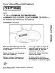
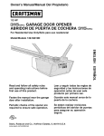
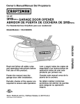
Owner's Manual/ManualDel Propietario
®
GARAGEDOOROPENER
ABRIDORDE PUERTADECOCHERA
ForResidentialUseOnly/S61opara usoresidencial
Model/Modelo 139.3043
I'll
Z
I'll
"O
;z=,
Z_
Read andfollow all safety rulesand operating
instructionsbeforefirst useof this product.
Fastenthe manualnear the garage doorafter
installation.
Periodic checksofthe openerare requiredto
ensuresafe operation.
DONOTenable the Timer-To-Closefeature if
you are installingthe garagedooropeneron
a one-piecedoor. The Timer-To-Closeis to be
usedONLYwithsectional doors.
Leery seguirtodaslas reglas de seguridady
las instruccionesde operaci6nantes de usar
esteproducto por primera vez.
Guardareste manualcerca de la puerta de la
cochera.
Se debenrealizar revisionesperi6dicas del
abridor de puertas para asegurarsu operaci6n
segura.
NOusoel caracteristicaTemporizadorpara
cierrase el abridorde la puerta es instalado
en un puertade unsola pieza. El caracteristica
temporizadorpara cierra es SOLOparauso con
puertasseccionales.
Sears Brands Management Corporation, Hoffman Estates, IL 60179 U.S.A
www.craftsman.com
TABLE
OF CONTENTS
Introduction
2-7
Adjustment
27-29
Safety symbol review and signal word review ...............
2
Introduction ........................................
Preparing your garage door .............................
Tools needed ........................................
3
3
Program the travel ...................................
28
Test the safety reversal system..........................
29
Test The Protector System® ............................
29
Planning ...........................................
4-5
27
Carton inventory ......................................
6
Battery Backup
30
Hardware inventory....................................
7
Install the Battery ....................................
30
Test the battery......................................
30
Assembly
8-11
Assemble the rail and install the trolley ....................
Fastenthe rail to the motor unit ..........................
8
8
Operation
31-35
Operation safety instructions ...........................
31
Install the idler pulley ..................................
Install the belt .......................................
9
10
Features .........................................
Door control ........................................
32
Set the tension and install the sprocket cover ..............
11
Smart control panel setup .............................
33
Programming .......................................
34
To erasethe memory .................................
34
To open the door manually .............................
35
Care of your opener ..................................
35
Installation
11-27
31-32
Installation safety instructions
Determine the header bracket location ....................
11
12
Install the header bracket ..............................
13
Attach the rail to the header bracket......................
14
Troubleshooting
36-37
Position the opener...................................
15
Repair Parts
38-39
Hang the opener .....................................
16
Rail assembly parts ..................................
38
Install the lights .....................................
17
Installation parts .....................................
38
Motor unit assembly parts .............................
39
Accessories
40
Warranty
40
Attach the emergency release rope and handle .............
Fastenthe door bracket .............................
17
18-19
Connect door arm to trolley ..........................
20-21
Attach the warning labels ..............................
Install the door control ..............................
21
22-23
Install The Protector System® ........................
23-25
Electrical requirements ................................
Aligning the safety reversing sensors ...................
26
Notes
Repair Parts and Service
41-42
BackCover
26-27
INTRODUCTION
Safety SymbolReviewand Signal WordReview
This garage door opener has been designed and tested to offer safe service provided it is installed, operated, maintained and tested in
strict accordancewith the instructions and warnings contained in this manual.
Mechanical
Electrical
When you see these Safety Symbols and Signal Words on the
following pages, they will alert you to the possibility of serious
injury or death if you do not comply with the warnings that
accompany them. The hazard may come from something
mechanical or from electric shock. Readthe warnings carefully.
When you see this Signal Word on the following pages, it will
alert you to the possibility of damageto your garage door and/or
the garage door opener if you do not comply with the cautionary
statements that accompany it. Readthem carefully.
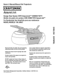
Preparingyour garage door
Before you begin:
• Disable locks.
• Removeany ropes connected to garage door.
• Completethe followingtest to make sure your garage door is
balanced and is not sticking or binding:
1. Lift the door about halfway as shown. Releasethe door. If
balanced, it should stay in place, supported entirely by its
springs.
2. Raise and lower the door to see if there is any binding or
sticking.
To prevent possible SERIOUSINJURYor DEATH:
• ALWAYScall a trained door systems technician if garage
door binds, sticks, or is out of balance. An unbalanced
garage door may NOT reverse when required.
• NEVERtry to loosen, move or adjust garage door, door
springs, cables, pulleys, brackets or their hardware, ALL of
which are under EXTREMEtension.
• DisableALL locks and remove ALL ropes connected to
garage door BEFOREinstalling and operating garage door
opener to avoid entanglement.
If your door binds, sticks, or is out of balance, call a trained
door systems technician.
To prevent damage to garage door and opener:
• ALWAYSdisable locks BEFOREinstalling and operating the
opener.
• ONLY operate garage door opener at 120V, 60 Hz to avoid
malfunction and damage.
z
Sectional Door
One-Piece Door
Tools needed
During assembly, installation and adjustment of the opener,
instructions will call for hand tools as illustrated below.
(optional)
_
Pencil
Tape Measure
Drill
_I(
Drill Bits 3/16"
5/16", and 5/32"
8
Stepladder
8
Hack Saw
Wire Cutters
Screwdriver
o
8
_sC"_et/_
_ dW;e,nc_dll2/i ''
Adjustable End Wrench
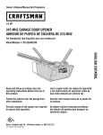
Planning
Identify the type and height of your garage door. Survey your
garage area to see if any of the conditions below apply to your
installation. Additional materials may be required. You may find it
helpful to refer back to this page and the accompanying
illustrations as you proceed with the installation of your opener.
Doyou have an access door in addition to the garage door? If
not, Model 139.53702 Emergency Key Releaseis required. See
Accessories page.
Look at the garage door where it meets the floor. Any gap
between the floor and the bottom of the door must not exceed
1/4" (6 mm). Otherwise, the safety reversal system may not
work properly. See Adjustment Step 2. Floor or door should be
repaired.
Depending on your requirements, there are several installation
steps which may call for materials or hardware not included in
the carton.
• Installation Step 1 - Look at the wall or ceiling above the
garage door. The header bracket must be securely fastened to
structural supports.
SECTIONALDOORINSTALLATION
• Installation Step 5 - Do you have a finished ceiling in your
garage? If so, a support bracket and additional fastening
hardware may be required.
• Doyou have a steel, aluminum, fiberglass or glass panel door?
If so, horizontal and vertical reinforcement is required
(Installation Step 8).
• Installation Step 12- Dependingupon garage construction,
extension brackets or wood blocks may be needed to install
sensors.
• The opener should be installed above the center of the door.
If there is a torsion spring or center bearing plate in the way
of the header bracket, it may be installed within 4 feet (1.22 m)
to the left or right of the door center. See Installation Steps 1
and 8.
• Installation Step 12 - Alternate floor mounting of the safety
reversing sensor will require hardware not provided.
• If your door is more than 7 feet (2.13 m) high, see rail
extension kits listed on Accessories page.
SECTIONALDOOR INSTALLATION
FINISHED CEILING
Support bracket &
fastening hardware
is required.
See page 16.
Horizontal and vertical reinforcement is
needed for lightweight garage doors
(fiberglass, steel, aluminum, door with
glass panels, etc.). See page 18 for details.
Rail
Header Wall
Extension Spring
OR
Torsion Spring
Wall- mounted
Door Control
AccessDoor
0
Header
Bracket
Gap between floor
and bottom of door
must not exceed 1/4" (6 mm).
CLOSED POSITION
Trolley
Stop Bolt
Safety
Reversing
Sensor
Trolley
Belt
Emergency Release
Rope & Handle
Header
Wall
Garage
Door
Curved
Door
Arm
Bracket
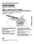
Planning(Continued)
ONE-PIECEDOOR INSTALLATIONS
Without a properly working safety reversal system, persons
(particularly small children) could be SERIOUSLYINJUREDor
KILLEDby a closing garage door.
• The gap between the bottom of the garage door and the floor
MUST NOT exceed 1/4" (6 mm). Otherwise, the safety
reversal system may NOTwork properly.
• The floor or the garage door MUST be repaired to eliminate
the gap.
• Generally, a one-piece door does not require reinforcement. If
your door is lightweight, refer to the information relating to
sectional doors in Installation Step 8.
• Dependingon your door's construction, you may need
additional mounting hardware for the door bracket (Step 8).
ONE-PIECEDOORWITHOUT TRACK
FINISHED CEILING
Support bracket
& fastening
hardware is required.
See page 16.
Rail
Header Wall
Motor Unit
Wall-Mounted
Door Control
J
Access
Door
CLOSEDPOSITION
Trolley Stop Bolt
Belt
o
Trolley
Emergency
Release
Rope & Handle
Safety Reversing
Sensor
SafetyReversing
Sensor
Gap between floor
and bottom of door must
not exceed 1/4" (6 mm).
Straight
Door
Arm
--
Curved
Door
Arm
Garage
Door
ONE-PIECEDOORWITH TRACK
CLOSEDPOSITION
Trolley Stop Bolt
Belt
Trolley
Access
Door
Header
Wall
Rail
Door
Bracket Straight
Door
Garage
Arm
Door
Gap between floor
and bottom of door
Safety
Reversing Sensor
must not exceed
1/4" (6 mm).
Safe_
Reversing Sensor
Emergency
Release
Rope &
Handle
CartonInventory
Your garage door opener is packaged in one carton which
contains the motor unit and all parts illustrated below.
Accessories will depend on the model purchased. If anything is
missing, carefully check the packing material.
Parts may be stuck in the foam. Hardware for assembly and
installation is shown on the next page. Savethe carton and
packing material until installation and adjustment is complete.
0
3-Button Remote Control (2)
Battery
Smart Control Panel®
Sprocketcover
with screws(3)
Trolley
Wireless Keypad
Rail
Center/Back
Sections
_1
•
_1
_
%
%
°oP
1,
°k
Io
°k
%
I°
%
Motor Unit with 2 Light Lenses
0
Idler Pulley
(In Hardware Bag)
Hanging Brackets
Belt
Rail
Front (header)
Section
Curved Door
Arm Section
Header Bracket
Door Bracket
O--'--
Safety Revers_
Sensor Bracket (2)
2-Conductor Bell Wire
White & White/Red
Hardware Bag_k
The Protector System ®
(2) Safety Reversing Sensors
(1 Sending Eye and 1 Receiving Eye)
with 2-Conductor White & White/Black
Bell Wire attached
Safety Labels
and Literature
(Packaged In Manual)
Straight Door
Arm Section
HardwareInventory
Separateall hardware and group as shown below for the assembly and installation procedures.
ASSEMBLYHARDWARE
_l]
!!!!!!!!!1)
Q
Bolt 1/4"-20xl-3/4"
(2)
Lock Nut
1/4"-20 (2)
Lock Washer
3/8" (1)
Nut
3/8" (1)
i
i
Spring/Trolley Nut (1)
Spring Nut Label
1o
Master
Link (2)
Idler Bolt (1)
Trolley Threaded Shaft (1)
INSTALLATIONHARDWARE
0
Carriage Bolt
1/4"-20xl/2" (2)
Wing Nut
1/4"-20 (2)
Ring
Fastener (3)
Handle
Nut 5/16"-18 (4)
F,,,,,,,,,,,D
Lag Screw
5/16"-9xl -5/8" (2)
1111111111111_
Hex Bolt
5/16"-18x7/8" (4)
Lock Washer 5/16" (5)
Insulated
Staples (30)
_ IIlllllllllllllllllllllll_
Screw
6ABx1-1/4" (2)
Lag Screw
5/16"-18xl -7/8" (2)
Self-Threading Screw
1/4"-14x5/8" (2)
Screw 6-32x1" (2)
Rope
Drywall Anchors (2)
o,
Clevis Pin
5/16"x1-1/2"(1)
Clevis Pin
Clevis Pin
5/16"x1" (1)
5/16"x1-1/4" (1)
ASSEMBLY
STEP
1
Assemble the Rail and Install the Trolley
To avoid installation difficulties, do not run the garage door
opener until instructedto do so.
To prevent INJURY from pinching, keep hands and fingers
away from the joints while assembling the rail.
The front rail has a cut out "window" at the door end
(see illustration). The hole above this windowis larger on the
top of the raft than on the bottom. A smaller hole 3-1/2" (8.9 cm)
away is close to the rail edge. Rotate the back rail so it has a
similar hole close to the oppositeedge, about 4-3/4" (12 cm)
from the far end.
Outer
Trolley
Inner
Trolley
1. Assemble the trolley by sliding the inner trolley into the outer
trolley.
Wear Pads
2. Removethe straight door arm and hanging bracket packaged
inside the front rail and set aside for Installation Steps 5 and 9.
NOTE: To prevent INJURY while unpacking the rail carefully
remove the straight door arm stored within the rail section.
3. Align the rail sections on a flat surface as shown and slide the
tapered ends into the larger ones. Tabs along the side will lock
into place.
RAIL (TOP)
KEEP LARGER
HOLE ON TOP
4. Placethe motor unit on packing material to protect the cover,
and rest the back end of the rail on top. For convenience, put a
support under the front end of the rail.
5. As a temporary stop, insert a screwdriver into the hole
10" (25 cm) from the front end of the rail, as shown.
Window Cut-Out
6. Checkto be sure there are 4 plastic wear pads inside the inner
trolley. If they became loose during shipping, check all packing
material. Snap them back into position as shown.
7. Slide the trolley assembly along the rail from the back end to
the screwdriver.
ASSEMBLY
STEP
2
Fasten the Rail to the Motor Unit
1. Insert a 1/4"-20xl-3/4" bolt into the cover protection bolt hole
on the back end of the rail as shown. Tighten securely with a
1/4"-20 lock nut. DO NOTovertighten.
To avoid SERIOUSdamage to garage door opener, use ONLY
those bolts/fasteners mounted in the top of the opener.
2. Removethe two bolts from the top of the motor unit.
3. Placethe "U" bracket, flat side down, on the motor unit and
align the bracket holes with the bolt holes. Fastenwith the
previously removed bolts.
4. Align the rail assembly with the top of the motor unit. Slide the
rail end onto the "U" bracket, all the way to the stops that
protrude on the top and sides of the bracket.
Bolts
I
"U" Bracket
Bolt
I
Cover
Protection
Bolt Hole _
HARDWARESHOWN ACTUALSIZE
I
I
Lock Nut i
Bolt 1/4"-20xl-3/4"
Lock Nut
1/4"-20
SLIDE RAIL TO STOPS
ON TOP AND SIDES
OF BRACKET
ASSEMBLY
STEP
3
Install the Idler Pulley
1. Laythe belt beside the rail, as shown. Graspthe end with the
hooked trolley connector and pass approximately 12" (30 cm)
of belt through the window. Keepthe ribbed side toward the
rail, and allow it to hang until Assembly Step 5.
2. Removethe tape from the idler pulley.
3. Placethe idler pulley into the window as shown.
4. Insert the idler bolt from the top through the rail and pulley.
Tighten with a 3/8" lock washer and nut underneaththe rail
until the lock washer is compressed.
5. Rotatethe pulley to be sure it spins freely.
6. Insert a 1/4"-20xl-3/4" bolt into the trolley stop hole in the
front of the rail as shown. Tighten securely with a 1/4"-20 lock
nut.
Bolt
Screwdriver
Trolley
Trolley
Stop Hole
Pulley
Washer
3/8"
Nut 3/8"
Trolley
Connector
Lock Nut
1/#'-20
HARDWARESHOWN ACTUALSIZE
Idler Bo__)
_[]
Bolt1/4"-28x1-3/4"
LockNut1/4"-20
Nut 3/8"
Lock Washer 3/8"
ASSEMBLY
STEP
4
Install the Belt
To avoid possible SERIOUSINJURYto fingers from moving
garage door opener:
• ALWAYS keep hand clear of sprocket while operating opener.
• Securely attach sprocket cover BEFOREoperating.
1. Pull the belt around the idler pulley and toward the trolley.
The ribbed side must contact the pufley.
2. Hook the trolley connector into the retaining slot on the trolley
as shown.
3. With the trolley against the screwdriver, dispense the
remainder of the belt along the rail length toward the motor
unit and around the sprocket. The sprocket teeth must engage
the belt.
4. Checkto make sure the belt is not twisted. Connectthe trolley
threaded shaft with the master link, as illustrated:
• Push pins of master link bar through holes in end of belt
and trolley threaded shaft.
• Push master link cap over pins and past pin notches.
• Slide clip-on spring over cap and onto pin notches until both
pins are securely locked in place.
5. Insert the trolley threaded shaft through the hole in the trolley.
Be sure the belt is not twisted.
Trolley Connector
Belt
Sprocket
Master Link
Clip-On Spring
Master
Link Cap
Y
Threaded
Shaft
Slot
Trolley
Connector
Idler
Pulley
Notch
Trolley
Threaded
Shaft
HARDWARESHOWN ACTUALSIZE
i
i
Master Link
[©
Trolley Threaded Shaft
10
Master
Link Bar
ASSEMBLY
STEP
5
Set the Tensionand Install the SprocketCover
1. By hand, thread the spring trolley nut on the threaded shaft
until it is finger tight against the trolley. Do not use any tools.
2. Removethe screwdriver.
3. Insert a flathead screwdriver tip into one of the nut ring slots
and brace it firmly against the trolley.
4. Tighten the spring trolley nut with an adjustable wrench or a
7/16" open end wrench about a quarter turn until the spring
releasesand snaps the nut ring against the trolley. This sets
the spring to optimum belt tension.
Nut Ring
5. Position the sprocket cover over the garage door opener
sprocket and attach with 8x3/8" hex screws.
Youhave now finished assemblingyour garage door opener.
Please read the following warningsbeforeproceedingto the
installation section.
Nut Ring
Hex Screws
i.,_
HARDWARESHOWN ACTUALSIZE
1-1/4"
FTER
(3.18 cm)
Sprocket
Hex Screw 8x3/8"
Spring/Trolley Nut
INSTALLATION
IMPORTANTINSTALLATIONINSTRUCTIONS
To reducethe risk of SEVEREINJURYor DEATH:
1. READAND FOLLOWALL INSTALLATIONWARNINGSAND
INSTRUCTIONS.
2. Install garage door opener ONLY on properly balancedand
lubricated garage door. An improperly balanceddoor may
NOT reverse when required and could result in SEVERE
INJURY or DEATH.
3. ALL repairs to cables, spring assemblies and other hardware
MUST be made by a trained door systems technician
BEFOREinstalling opener.
4. Disable ALL locks and remove ALL ropes connected to
garage door BEFOREinstalling opener to avoid entanglement.
5. Install garage door opener 7 feet (2.1 m) or more above
floor.
6. Mount the emergency releasewithin reach, but at least 6 feet
(1.83 m) above the floor and avoiding contact with vehicles
to avoid accidental release.
7. NEVERconnect garage door opener to power source until
instructed to do so.
8. NEVERwear watches, rings or loose clothing while installing
or servicing opener. They could be caught in garage door or
opener mechanisms.
11
9. Install wall-mounted garage door control:
• within sight of the garage door.
• out of reach of children at minimum height of
5 feet (1.5 m).
• away from ALL moving parts of the door.
10. Placeentrapment warning label on wall next to garage door
control.
11. Placemanual release/safety reverse test label in plain view
on inside of garage door.
12. Upon completion of installation, test safety reversal
system. Door MUST reverse on contact with a
1-1/2" (3.8 cm) high object (or a 2x4 laid flat) on the floor.
13. To avoid SERIOUSPERSONALINJURYor DEATHfrom
electrocution, disconnect ALL electric and battery power
BEFOREperforming ANY service or maintenance.
14. DO NOTenable the Timer-to-Close functionality if operating
either one-piece or swinging garage doors. To be enabled
ONLYwhen operating a sectional door.
INSTALLATION
STEP 1
Determine the HeaderBracketLocation
Un.f!nished
To prevent possible SERIOUSINJURYor DEATH:
• Headerbracket MUST be RIGIDLY fastened to structural
support on header wall or ceiling, otherwise garage door
might NOT reverse when required. DONOT install header
bracket over drywall.
• Concrete anchors MUST be used if mounting header bracket
or 2x4 into masonry.
• NEVERtry to loosen, move or adjust garage door, springs,
cables, pulleys, brackets, or their hardware, ALL of which are
under EXTREMEtension.
Ceiling _
BRACKETMOUNTCEILINGOPTIO
Header Wall
Vertical Centerline
of Garage Door
2x4
Structural
Suppo_s
• ALWAYScall a trained door systems technician if garage
door binds, sticks, or is out of balance. An unbalanced
garage door might NOT reversewhen required.
Installation procedures vary according to garage door types.
Follow the instructions which apply to your door.
1. Close the door and mark the inside vertical centerline of the
garage door.
2. Extend the line onto the header wall above the door.
You can fasten the header bracketwithin 4 feet (1.22 m) of
the left or right of the doorcenter only if a torsion springor
center bearingplate is in the way; or you can attach it to the
ceiling (see page 13) when clearance is minimal. (It may be
mountedon the wall upsidedown if necessary,to gain
approximately1/2" (1 cm))
HeaderWall
"_[_",--2" (5 cm)
If you need to install the header bracket on a 2x4 (on wall or
ceiling), use lag screws (not provided) to securely fasten the
2x4 to structural supports as shown here and on page 13.
Track
HeaderWall
Highest Point
of Travel
3. Open your door to the highest point of travel as shown. Draw
an intersecting horizontal line on the header wall above the
high point:
Track
HighestPoint
of Travel
--Door
T
• 2" (5 cm) above the high point for sectional door and
one-piece door with track.
• 8" (20 cm) above the high point for one-piece door without
track.
Sectional door with curved track
One-piece door with horizontal track
This height will provide travel clearance for the top edge of the
door.
NOTE:If the total number of inches exceedsthe height available
in your garage, use the maximum height possible, or refer to
page 13 for ceiling installation.
-leader Wall
Header Wall
8" (20 cm)
',- 8" (20 cm)
Door
Highest
Point
of Travel
Highest
Point
of Travel
Hardware
Pivot
One-piecedoorwithouttrack:
jambhardware
12
One-piece door without track:
pivot hardware
INSTALLATION
STEP
2
Install the Header Bracket
Wall Mount
You can attach the header bracket either to the wall above the
garage door, or to the ceiling. Follow the instructions which will
work best for your particular requirements. Do not install the
header bracket over drywall. If installing into masonry, use
concreteanchors(not provided).
WALL HEADERBRACKETINSTALLATION
• Center the bracket on the vertical centerline with the bottom
edge of the bracket on the horizontal line as shown (with the
arrow pointing toward the ceiling).
Optional
Mounting Holes
• Mark the vertical set of bracket holes. Drill 3/16" pilot holes and
fasten the bracket securely to a structural support with the
hardware provided.
-
Vertical
Centerline
of Garage Door
Header Wall
2x4
Structural
Suppo_
_
Lag Screws
5/16"-9xl-5/8"
HARDWARESHOWN ACTUALSIZE
Door Spring
J
I
Horizontal
Line
Lag Screw
5/16"-9xl -5/8"
i
Highest Point of
Garage DoorTravel
Vertical
Centerline
of Garage Door
CEILINGHEADERBRACKETINSTALLATION
• Extend the vertical centerline onto the ceiling as shown.
• Center the bracket on the vertical mark, no more than
6" (15 cm) from the wall. Make sure the arrow is pointing away
from the wall. The bracket can be mounted flush against the
ceiling when clearance is minimal.
• Mark the side holes. Drill 3/16" pilot holes and fasten bracket
securely to a structural support with the hardware provided.
- Finished Ceiling Vertical Centerline
of Garage Door
I i
Bracket
6" (15 cm) M
Ceiling Mounting Holes
Door
Spring
Header Wall -
Centerline
of GarageDoor
13
INSTALLATION
STEP
3
Attach the Raft to the Header Bracket
1. Position the opener on the garage floor below the header
bracket. Use packing material as a protective base.
NOTE:If the door spring is in the way, you will need help. Have
someone hold the opener securely on a temporary support to
allow the rail to clear the spring.
2. Position the rail bracket against the header bracket.
3. Align the bracket holes and join with a clevis pin as shown.
4. Insert a ring fastener to secure.
HeaderWall
HeaderBracket
IdlerPulley
0
Header
Mounting
Hole
--
Garage
Door
__
HARDWARESHOWN ACTUALSIZE
oj
ClevisPin 5/16"x1-1/2"
0
Ring Fastener
14
Opener Ca_on or
Tempora_
Support
INSTALLATION
STEP
4
Positionthe Opener
To prevent damage to garage door, rest garage door opener rail
on 2x4 placed on top section of door.
Follow instructions which apply to your door type as illustrated.
SECTIONALDOOROR ONE-PIECEDOORWITH TRACK
A 2x4 laid flat is convenient for setting an ideal door-to-rail
distance.
1. Removefoam packaging.
2. Raisethe opener onto a stepladder. You will need help at this
point if the ladder is not tall enough.
Rail
3. Open the door all the way and place a 2x4 laid flat on the top
section beneath the rail.
4. If the top section or panel hits the trolley when you raise
the door, pull down on the trolley releasearm to disconnect
inner and outer sections. Slide the outer trolley toward the
motor unit. The trolley can remain disconnected until
Installation Step 12 is completed.
the correct mounting height
from ceiling.
Trolley
Release Arm
ENGAGED
RELEASED
ONE-PIECEDOORWITHOUTTRACK
A 2x4 on its side is convenient for setting an ideal
door-to-rail distance.
Header Bracket
1. Removefoam packaging.
2. Raisethe opener onto a stepladder. You will need help at this
point if the ladder is not tall enough.
3. Open the door all the way and place a 2x4 on its side on the
top section of the door beneath the rail.
4. The top of the door should be level with the top of the motor
unit. Do not position the opener more than 4" (10 cm) above
this point.
15
INSTALLATION
STEP
5
Hang the Opener
To avoid possible SERIOUSINJURYfrom a falling garage door
opener, fasten it SECURELYto structural supports of the
garage. Concrete anchors MUST be used if installing ANY
brackets into masonry.
Three representative installations are shown. Yours may be
different. Hanging brackets should be angled (Figure 1) to provide
rigid support. On finished ceilings (Figures 2 and 3), attach a
sturdy metal bracket to structural supports before installing the
opener. This bracket and fastening hardware are not provided.
1. Measure the distance from each side of the motor unit to the
structural support.
FigureI
2. Cut both pieces of the hanging bracket to required lengths.
orts
3. Drill 3/16" pilot holes in the structural supports.
4. Attach one end of each bracket to a support with
5/16"-18xl -7/8" lag screws.
5. Fastenthe opener to the hanging brackets with
5/16"-18x7/8" hex bolts, lock washers and nuts.
6. Checkto make sure the rail is centered over the door
(or in line with the header bracket if the bracket is not centered
above the door).
Lag Screws
5/16"-18xl -7/8"
Bolt 5/16"-18x7/8"
Lock Washer 5/16"
Nut 5/16"-18
7. Removethe 2x4. Operatethe door manually. If the door hits
the rail, raise the header bracket.
NOTE:DO NOT connect power to opener at this time.
Figure2
FINISHED CEILING
._(Not Provided)
Bolt 5/16"-18x7/8"
Lock Washer 5/16"
Nut 5/16"-18
Bolt 5/16"-18x7/8"
Lock Washer 5/16"
Nut 5/16"-18
HARDWARESHOWN ACTUALSIZE
Lag Screw 5/16 ,,_18xl _7/8 ,,
Figure3
Hex Bolt
5/16"-18x7/8"
Nut 5/16"-18
Lag Screws
5/16"-18xl-7/8"
Lock Washer 5/16"
Bolt 5/16"-18x7/8"
Lock Washer 5/16"
Nut 5/16"-18
16
(Not Provided)
Bolt 5/16"-18x7/8"
Lock Washer 5/16"
Nut 5/16"-18
INSTALLATION
STEP
6
Install the Lights
To prevent possible OVERHEATINGof the end panel or light
socket:
1. Press the releasetabs on both sides of lens. Gently rotate lens
back and downward until the lens hinge is in the fully open
position. Do not remove the lens.
• Use ONLYA19 incandescent or compact fluorescent light
bulbs.
2. Insert an A19 incandescent or compact fluorescent light bulb
(100 watt maximum), into the light socket. The lights will turn
ON and remain lit for approximately 4-1/2 minutes when power
is connected. Then the lights will turn OFF.
• DONOT use incandescent bulbs larger than IOOW.
• DONOT use compact fluorescent light bulbs larger than
26W (IOOW) equivalent.
• DONOT use halogen bulbs.
• DONOT use short neck or specialty light bulbs.
3. Reversethe procedure to close the lens.
4. If the bulbs burn out prematurely due to vibration, replacewith
a garage door opener bulb. UseA19, standard neck garage
door opener for replacement.
Compact Fluorescent -Light Bulb
NOTE: Use only standard light bulbs. The use of short neck or
speciality light bulbs may overheat the endpanel or light socket.
]_
Release Tab
or
100Watt(Max)
'
Standard Light Bulb
Hinge
100 Watt(Max)
StandardLight Bulb
Compact Fluorescent
Light Bulb
INSTALLATION
STEP
7
Attach the Emergency Release Rope and Handle
To prevent possible SERIOUSINJURYor DEATHfrom a falling
garage door:
• If possible, use emergency releasehandle to disengage
trolley ONLYwhen garage door is CLOSED.Weak or broken
springs or unbalanceddoor could result in an open door
falling rapidly and/or unexpectedly.
• NEVERuse emergency releasehandle unless garage doorway
is clear of persons and obstructions.
• NEVERuse handle to pull door open or closed. If rope knot
becomes untied, you could fall.
1. Thread one end of the rope through the hole in the top of the
red handle so "NOTICE"reads right side up as shown, Secure
with an overhand knot at least1" (2.5 cm) from the end of the
rope to prevent slipping,
2. Thread the other end of the rope through the hole in the release
arm of the outer trolley.
3. Adjustrope lengthso the handle is 6 feet (1.83 m) above the
floor, Ensurethat the rope and handle clear the tops of all
vehicles to avoid entanglement, Secure with an overhand knot,
NOTE:If it is necessary to cut the rope, heat seal the cut end with
a match or lighter to prevent unraveling.
Trolley
Trolley
Release Arm
1
Overhand
Emergency
_
Release Handle _
17
Knot
INSTALLATION
STEP
8
Fasten the Door Bracket
Fiberglass, aluminum or lightweight steel garage doors WILL
REQUIREreinforcement BEFOREinstallation of door bracket.
Contact your door manufacturer for reinforcement kit.
Follow instructions which apply to your door type as illustrated
below or on the following page.
A horizontal reinforcementbrace shouldbe long enoughto be
securedto two or three vertical supports,A vertical
reinforcementbrace shouldcover the height of the top panel,
Figure 1 shows one piece of angle iron as the horizontal brace.
For the vertical brace, 2 pieces of angle iron are used to create a
U-shaped support. The best solution is to check with your garage
door manufacturer for an opener installation door reinforcement
kit.
NOTE:Many door reinforcement kits provide for direct
attachment of the clevis pin and door arm. In this caseyou will
not need the door bracket, proceed to Step 9.
Door
Bracket
Location
SECTIONALDOORS
1. Center the door bracket on the previously marked vertical
centerline used for the header bracket installation. Note correct
UP placement, as stamped inside the bracket.
HORIZONTALAND VERTICAL
REINFORCEMENTiS NEEDEDFOR
LiGHTWEiGHTGARAGE DOORS
(FIBERGLASS, ALUMINUM, STEEL,
DOORS WiTH GLASSPANEL, ETC.).
(NOT PROVIDED)
Vertical
Centerline
of Garage
Door
2. Position the top edge of the bracket 2"-4" (5-10 cm) below the
top edge of the door, OR directly below any structural support
across the top of the door.
Figure 1
3. Mark, drill holes and install as follows, depending on your
door's construction:
Vertical Reinforcement
Metal or light weightdoors using a vertical angle iron brace
between the doorpanel supportand the door bracket:
Vertical
Centerline
of GarageDoor
/
Vertical Reinforcement
• Drill 3/16" fastening holes. Securethe door bracket using the
two 1/4"-14x5/8" self-threading screws (Figure 2A).
Vertical Centerline
of Garage Door
• Alternately, use two 5/16" bolts, lock washers and nuts
(not provided) (Figure 2B).
/
Bolt
5/16"-18x2"
(Not
Provided)
Door
Bracket
Metal, insulated or light weight factoryreinforced doors:
• Drill 3/16" fastening holes. Securethe door bracket using the
self-threading screws (Figure 3).
WoodDoors:
Lock Washer 5/16"
Door Bracket
Self-Threading
Screw 1/4"-14x5/8"
• Use top and bottom or side to side door bracket holes. Drill
5/16" holes through the door and secure bracket with 5/16"x2"
carriage bolts, lock washers and nuts (not provided) (Figure 4).
,'/'_"
Nut
5/16"-18
I
Figure2B
Figure2A
Bolt 5/16"-18x2"
(Not Provided)
NOTE: The 1/4"-14x5/8" self-threading screws are not intended for
use on wood doors.
Vertical
Centerline
of Garage
Door
--
HARDWARE
SHOWN ACTUAL
SIZE
_-_-
Self-Threading
Screw
1/4"-14x5/8"
UP
"_Self-Threading
._"
Figure3
18
Screw 1/4"-14x5/8" I
Inside Edge of Door or
Reinforcement Board
Vertical
Centerline
of Garage
Door
Figure4
Fasten the Door Bracket (Continued)
ONE-PIECEDOORS
Please read and comply with the warnings and reinforcement
instructions on the previous page. They apply to one-piece doors
also.
• Center the door bracket on the top of the door, in line with the
header bracket as shown. Mark either the left and right, or the
top and bottom holes.
• Metal Doors: Drill 3/16" pilot holes and fasten the bracket with
the 1/4"-14x5/8" self-threading screws provided.
HARDWARESHOWN
ACTUAL SIZE
• WoodDoors: Drill 5/16" holes and use 5/16"x2" carriage bolts,
lock washers and nuts (not provided) or 5/16"x1-1/2" lag
screws (not provided) depending on your installation needs.
NOTE: Thedoor bracket may be installed on the top edge of the
door if required for your installation. (Refer to the dotted line
optional placement drawing.)
Self-ThreadingScrew
1/4"-14x5/8"
'__
'
Door
Header Wall
2x4 Support
m
Finished Ceiling --
Screw
Self-Threading
1/4"-14x5/8"
Bracket_
.......
,ii,
.....
!!iJ_iiiii!!iii//i_iiiii/iiiii
Door
Bracket
METAL DOOR
Optional
Placement
of Door
Bracket
Vertical
Centerline of
Garage Door
HORIZONTALAND VERTICAL
REINFORCEMENTIS NEEDED
FOR LIGHTWEIGHTGARAGE
DOORS(FIBERGLASS, ALUMINUM,
STEEL, DOORSWITH GLASS
PANEL, ETC.). (NOT PROVIDED)
Nut
5/16"-18 _
_
_
Lock
Washer
,i
i
,
Door _
Bracket
_
5/16"
Top of Door
Carriage Bolt
_
For a door with no exposed framing,
or for the optional installation, use
lag screws 5/16"x1-1/2" (Not Provided)
to fasten door bracket.
19
b
(Not Provided)
5/16"x2"
WOOD DOOR
INSTALLATION
STEP
9
Pulley
Connect Door Arm to Trolley
i
Follow instructions which apply to your door type as illustrated
below and on the following page.
cm) min. __.),,
Figure 1
SECTIONALDOORSONLY
Outer
Trolley
Make sure garage door is fully closed. Pull the emergency release
handle to disconnect the outer trolley from the inner trolley. Slide
the outer trolley back (away from the pulley) about 8" (20 cm) as
shown in Figures 1, 2 and 3.
Clevis Pin
5/16"x1"
Emergency
- Release
Handle
1. Fastenstraight door arm section to outer trolley with the
5/16"x1" clevis pin. Secure the connection with a ring fastener
(Figure 1).
Straight
DoorArm
2. Fastencurved section to the door bracket in the same way,
using the 5/16"x1-1/4" clevis pin.
Curved Door Arm
"
IMPORTANT:Thegroove on the straight door arm MUST face
away from the curved door arm (Figure 4).
3. Bring arm sections together. Find two pairs of holes that line up
and join sections. Select holes as far apart as possible to
increase door arm rigidity (Figure 2).
Clevis Pin 5/16"x1-1/4"
Pulley
Figure 2
Hole alignment alternative (Figure3):
• If holes in curved arm are above holes in straight arm,
disconnect straight arm. Cut about 6" (15 cm) from the solid
end. Reconnect to trolley with cut end down as shown.
• Bring arm sections together.
• Find two pairs of holes that line up and join with bolts, lock
washers and nuts.
Bolts
Pull the emergency releasehandle toward the opener at a 45°
angle so that the trolley releasearm is horizontal. Trolley will
re-engage automatically when opener is operated during the
adjustments.
Door Bracket
Pulley
Figure 3
/ !LS"
(20 cm) rain. __U
Trolley f
Stop Bolt
Lock
11
11
11
Washers _/
5/16" /_!
/ /_/
Nuts
HARDWARESHOWN ACTUALSIZE
0
Nut 5/16"-18
Lock Washer 5/16"
Bol
Ring Fastener
"_
ol
Clevis Pin
5/16"xl" (Trolley)
Clevis Pin
5/16"x1-1/4"(Door Bracket)
Figure 4
Hex Bolt
5/16"-18x7/8"
2O
Cut this end
CORRECT
INCORRECT
ConnectDoorArm to Tro//ey(Continued)
ALL0NE-PIECEDOORS
IMPORTANT."Thegroove on the straight door arm MUST face
away from the curved door arm (Figure 5).
Figure5
INCORRECT
CORRECT
1. Close the door. Disconnect the trolley by pulling the emergency
releasehandle.
2. Fastenthe straight door arm and the curved door arm together
to the longest possible length (with a 2 or 3 hole overlap).
3. Attach the straight door arm to the door bracket using the
5/16"x1-1/4" clevis pin. Secure with the ring fastener.
4. Attach the curved door arm to the trolley using the 5/16"x1"
clevis pin. Secure with the ring fastener.
5. Pull the emergency release handle toward the garage door
opener until the trolley releasearm is horizontal.
Trolley
Pulley
Stop Bolt
Inner
Trolley
Outer
Trolley
Ring
Ring
Fastener
Nuts
5/16"-18
Fastener_
DoorArm
Door
Bracket
strai0htLock
Washers-------_
,
Q
5/16"
Clevis Pin
5/16"xl"
DoorArm
Clevis Pin
5/16"x 1-1/4"
Bolts
5/16"-18x7/8"
Emergency
Release Handle
INSTALLATION
STEP
10
Attach the Warning Labels
1. Attach the entrapment warning label on the wall near the door
control with tacks or staples.
2. Attach the manual release/safetyreverse test label in a visible
location on the inside of the garage door.
21
INSTALLATION
STEP
Install the Door Control
11
INTRODUCTION
To prevent possible SERIOUSINJURYor DEATHfrom
electrocution:
NOTE:Older Craftsman accessories and third party products are
not compatible.
• Be sure power is NOT connected BEFOREinstalling door
control.
Your garage door opener is compatible with up to 2 door controls.
• Connect ONLYto 12 VOLTlow voltage wires.
To prevent possible SERIOUSINJURYor DEATHfrom a closing
garage door:
• Install door control within sight of garage door, out of reach
of children at a minimum height of 5 feet (1.5 m), and away
from ALL moving parts of door.
• NEVERpermit children to operate or play with door control
push buttons or remote control transmitters.
• Activate door ONLYwhen it can be seen clearly, is properly
adjusted, and there are no obstructions to door travel.
• ALWAYS keepgarage door in sight until completely closed.
NEVERpermit anyone to cross path of closing garage door.
Install the door control within sight of the door at a minimum
height of 5 feet (1.5 m) where small children cannot reach, and
away from the moving parts of the door.
NOTE:For gang box installations it is not necessary to drill holes
or instafl the drywafl anchors. Use the existing holes in the gang
box (Figure 1).
WIRETHE DOORCONTROL(FIGURE2)
1. Strip 7/16 inch (11 mm) of insulation from one end of the wire
and separate the wires.
2. Connect one wire to each of the two screws on the back of the
door control. The wires can be connected to either screw.
Pre-wired installations:Choose any two wires to connect, but
make note of which wires are used so that the correct wires are
connected to the garage door opener in a later step.
HARDWARESHOWN ACTUALSIZE
-Ni]i-7-Ni]-iN-q-fii>
Screw 6ABx1-1/4"
(std installation)
Insulated
Staples
MOUNTTHE DOORCONTROL(FIGURE3)
1. Mark the location of the bottom mounting hole and drill a 5/32
inch (4 mm) hole.
(pre-wired)
Drywall Anchors
2. Install the bottom screw, allowing 1/8 inch (3 mm) to protrude
from the wall.
Figure 1
3. Position the bottom hole of the door control over the screw and
slide down into place.
PRE-WIRED INSTALLATIONS:
Choose any two wires to
connect, but make note of
which wires are used.
4. Lift the push bar and mark the top hole.
5. Removethe door control from the wall and drill a 5/32 inch
(4 mm) hole for the top screw.
6. Position the bottom hole of the door control over the screw and
slide down into place. Attach the top screw.
6-32x1"
e
Figure2
Figure3
Top Mounting Hole
Bell Wire
Terminal
Screws
Screw
6ABx1-1/4"
BottomMountingHole
Screw
6ABx1-1/4"
22
ire
Screw
6-32x1"
Install the Door Control (Continued)
WIRETHE DOORCONTROLTO THE GARAGEDOOROPENER
(FIGURE4)
Figure4
DoorControlConnections
Pre-wired installations:When wiring the door control to the
garage door opener make sure you use the same wires that are
connected to the door control.
1. Run the white and red/white wire from the door control to the
garage door opener. Attach the wire to the wall and ceiling with
the staples (not applicable for gang box or pre-wired
installations). Do not piercethe wire with the staple as this may
cause a short or an open circuit.
Strip wire 7/16" (11 mm)
2. Strip 7/16 inch (11 mm) of insulation from the other end of the
wire near the garage door opener.
3. Connect the wire to the red and white terminals on the garage
door opener.
INSTALLATION
STEP
ro insert or release wire, push
in tab with screwdriver tip
12
Install TheProtectorSystem®
Be sure power is NOTconnected to the garage door opener
BEFOREinstalling the safety reversing sensor.
To prevent SERIOUSINJURY or DEATHfrom a closing garage
door:
IMPORTANTINFORMATIONABOUTTHE SAFETYREVERSING
SENSOR
The safety reversing sensor must be connected and aligned
correctly before the garage door opener will move in the down
direction.
• Correctly connect and align the safety reversing sensor. This
required safety device MUST NOT be disabled.
• Install the safety reversing sensor so beam is NO HIGHER
than 6" (15 cm) above garage floor.
The sending sensor (with an amber LED)transmits an invisible
light beam to the receiving sensor (with a green LED). If an
obstruction breaks the light beam while the door is closing, the
door will stop and reverse to the full open position, and the
garage door opener lights will flash 10 times.
NOTE:For energy efficiency the garage door opener will enter
sleep mode when the door is fully closed. Thesleep mode shuts
the garage door opener down until activated. The sleep mode is
sequenced with the garage door opener light bulb; as the light
bulb turns off the sensor LEDs will turn off and whenever the
garage door opener lights turn on the sensor LEDs will light. The
garage door opener will not go into the sleep mode until the
garage door opener has completed 5 cycles upon power up.
When installing the safety
• Sensors are installed inside the garage,one on either side of
the door.
• Sensors are facing each other with the lenses aligned and the
receiving sensor lens does not receive direct sunlight.
• Sensors are no more than 6 inches (15 cm) above the floor and
the light beam is unobstructed.
ing sensors check the following:
Safety Reversing Sensor
6" (15 cm) max. above floor
Facing the doorfrom inside the garage
Safety Reversing Sensor
6" (15 cm) max. above floor
Invisible Light Beam
Protection Area
23
Instal/The ProtectorSystem® (Continued)
Figure I
INSTALLINGTHE BRACKETS
Be sure power to the opener is disconnected.Install and align
the brackets so the sensors will face each other across the garage
door, with the beam no higher than 6" (15 cm) above the floor.
They may be installed in one of three ways, as follows.
DOORTRACK MOUNT (RIGHT SIDE)
iDoor
\ Track
Lip
,/
Indicator
Garage door trackinstallation (preferred):
Light
• Slip the curved arms over the rounded edge of each door track,
with the curved arms facing the door. Snap into place against
the side of the track. It should lie flush, with the lip hugging the
back edge of the track, as shown in Figure 1.
If your door track will not support the bracket securely, wall
installation is recommended.
Waft installation (Figures2 & 3):
Figure2
WALL MOUNT (RIGHT SIDE)
• Placethe bracket against the wall with curved arms facing the
door. Be sure there is enough clearancefor the sensor beam to
be unobstructed.
Fasten Wood Block to Wall with
Screws (not provided)
• If additional depth is needed,an extension bracket
(see Accessories) or wood blocks can be used.
Indicator
Light
• Use bracket mounting holes as a template to locate and drill (2)
3/16" diameter pilot holes on the wall at each side of the door,
no higher than 6" (15 cm) above the floor.
• Attach brackets to wall with lag screws (not provided).
_
Safety
Reversing
Sensor
Bracket
Lag Screws
(not provided)
Lens ......
• If using extension brackets or wood blocks, adjust right and left
assemblies to the same distance out from the mounting
surface. Make sure all door hardware obstructions are cleared.
Figure3
Floor installation (Figure 4):
'_
WALL MOUNT (RIGHT SIDE)
• Use wood blocks or extension brackets (see Accessories) to
elevate sensor brackets so the lenses will be no higher than
6" (15 cm) abovethe floor.
Extension Bracket
Accessories)
(Provided with
Extension Bracket)
• Carefully measure and place right and left assemblies at the
same distance out from the wall. Be sure all door hardware
obstructions are cleared.
• Fastento the floor with concrete anchors as shown.
(Provided with
Extension Bracket) _'"
%7"
Indicator
Lens
Safety
Reversing
Sensor
Bracket
Light
Figure4
FLOORMOUNT (RIGHT SIDE)
HARDWARESHOWN ACTUALSIZE
i
;
Carriage Bolt
1/4"-20xl/2"
Wing Nut
1/4"-20
ttach with
Concrete
Anchors
(not provided)
Indicator
Light
Staples
Reversing
Sensor
Bracket
24
Insta// TheProtectorSystem® (Continued)
MOUNTINGANDWIRING THE SAFETYREVERSINGSENSORS
Figure 5
Mounting:
• Slide a 1/4"-20xl/2" carriage bolt head into the slot on each
sensor. Use wing nuts to fasten sensors to brackets, with
lenses pointing toward each other across the door. Be sure the
lens is not obstructed by a bracket extension (Figure 5).
Carriage
Bolt
• Finger tighten the wing nuts.
OptionA -/nsta//ation WithoutPre-Wiring:
Figure 6
• Run the bell wire from both sensors to the garage door opener.
Attach the wire to the wall and ceiling with the staples
(Figure 6).
Option B - Pre-Wired /nsta//ation:
If your garage already has wires installed for the safety reversing
sensors, follow the instructions below:
• Cut the end of the safety sensor wire, making sure there is
enough wire to reachthe pre-installed wires from the wall
(Figure 7).
Figure7
Figure 8
• Separatethe safety sensor wires and strip 7/16 inch (11 mm)
of insulation from each end. Choose two of the pre-installed
wires and strip 7/16 inch (11 mm) of insulation from each end.
Make sure that you choose the same color pre-installed wires
for each sensor (Figure 8).
Safety Reversing
Sensor Wires
• Connect the pre-installed wires to the sensor wires with wire
nuts making sure the colors correspond for each sensor
(Figure 9).
7/16"
Pre-lnstalled Wires
CONNECTTO GARAGEDOOROPENER:
• Strip 7/16 inch (11 ram) of insulation from each set of wires.
Separatewhite and white/black wires sufficiently to connect to
the opener quick-connect terminals. Twist like colored wires
together. Insert wires into quick-connect holes: white to white
and white/black to grey (Figure 10).
Figure 9
(11 mm)
Not Provided
Safety
Reversing
Sensor
Wires
Pre-lnstalled
Wires
White/Black
Connect Wire to
Quick-Connect Terminals
Figure10
Bell Wire
m
Finished
Ceiling
1. Strip wire 7/16" (11 mm)
2. Twist like colored
wires together
3afety Reversing
Sensor
Safety Reversing
Sensor
25
Invisible Light Beam
Protection Area
3. To insert or release
wire, push in tab with
screwdriver tip
Red White Grey
Quick-Connect Terminals
INSTALLATION
STEP
13
Electrical Requirements
To prevent possible SERIOUSINJURYor DEATHfrom
electrocution or fire:
To avoid installationdifficulties, do not run the opener at this
time.
• Be sure power is NOT connected to the opener, and
disconnect power to circuit BEFOREremoving cover to
establish permanent wiring connection.
• Garage door installation and wiring MUST be in compliance
with ALL local electrical and building codes.
• NEVERuse an extension cord, 2-wire adapter, or change plug
in ANY way to make it fit outlet. Be sure the opener is
grounded.
To reduce the risk of electric shock, your garage door opener has
a grounding type plug with a third grounding pin. This plug will
only fit into a grounding type outlet. If the plug doesn't fit into the
outlet you have, contact a qualified electrician to install the proper
outlet.
THEREARE TWO OPTIONSFORCONNECTINGPOWER:
TYPICALWIRING (OPTIONA)
1. Plug in the garage door opener into a grounded outlet.
OptionA
2. DO NOT run garage door opener at this time.
PERMANENTWIRING (OPTIONB)
If permanentwiring is required byyour local code, refer to the
following procedure.To make a permanent connection through
the 7/8" hole in the top of the motor unit (according to local code):
RIGHT
WRONG
1. Be sure power is NOT connected to the opener, and
disconnect power to circuit.
2. Removethe garage door opener cover and set aside.
PERMANENT WIRING CONNECTION
Option B
3. Removethe attached green ground terminal.
4. Cut black and white wires and strip away 1/2" (1 cm) of
insulation, 3" (7.5 cm) before spade terminals.
Ground Wire
5. Removethe power cord from opener.
Black
Wire
Ground Tab
Green Ground
Screw
6. Install a conduit or flex cable adapter to the 7/8" hole.
7. Run wires through conduit, cut to proper length and strip
insulation.
8. Attach with wire nuts provided. Attach the ground wire to the
green ground screw. The opener must be grounded.
9. Properly secure wire under plastic ties so that wire does not
come in contact with moving parts.
WireNuts
10. Reinstall the cover. DONOT run garage door opener at this
time.
INSTALLATION
STEP
14
Aligningthe SafetyReversingSensors
The door will not close if the sensorshave not been installed
and aligned correctly.
When the light beam is obstructed or misaligned while the door is
closing, the door will reverse and the garage door opener lights
will flash ten times. If the door is already open, it will not close.
.
0
1. Check to make sure the LEDs in both sensors are glowing
steadily. The LEDs in both sensors will glow steadily if they
are aligned and wired correctly.
the receiving sensor is in
_irect sunlight, switch it with
sending sensor so it is on the
The sensors can be aligned by
loosening the wing nuts, aligning
the sensors, and tightening the
wing nuts.
opposite side of the door.
Amber LED
i
SENDING SENSOR
26
/(
/
/f
Green LED
RECEIVINGSENSOR
Aligning the Safety Reversing Sensors (Continued)
IF THE AMBERLED ONTHE SENDINGSENSORIS NOT
GLOWING:
IF THE GREENLED ON THE RECEIVINGSENSORIS NOT
GLOWING:
1. Make sure there is power to the garage door opener.
2. Make sure the sensor wire is not shorted/broken.
1. Make sure the sensor wire is not shorted/broken.
2. Make sure the sensors are aligned.
3. Make sure the sensor has been wired correctly: white wires to
white terminal and white/black wires to grey terminal.
ADJUSTMENT
Introduction
Without a properly installed safety reversal system, persons
(particularly small children) could be SERIOUSLYINJUREDor
KILLED by a closing garage door.
• Incorrect adjustment of garage door travel limits will interfere
with proper operation of safety reversal system.
• NEVERuse force adjustments to compensate for a binding or
sticking garage door.
• After ANY adjustments are made, the safety reversal system
must be tested. Door MUST reverse on contact with 1-1/2"
(3.8 cm) high object (or 2x4 laid flat) on floor.
Your garage door opener is designed with electronic controls to
make setup and adjustments easy. The adjustments allow you to
program where the door will stop in the open (UP) and close
(DOWN) position. The electronic controls sense the amount of
force required to open and close the door. The force is adjusted
automatically when you program the travel and cannot be
changed.
NOTE:If anything interferes with the door's upward travel it will
stop. If anything interferes with the door's downward travel, it will
reverse.
To prevent damage to vehicles, be sure fully open door
provides adequateclearance.
UP (Open)
DOWN (Close)
ONE-PIECEDOORSONLY
PROGRAMMINGBUTTONS
When setting the UP travel for a one-piece door ensure that the
door does not slant backwards when fully open (UP). If the door
is slanted backwards this will cause unnecessary bucking and/or
jerking when the door is opening or closing.
The programming buttons are located on the left side panel of the
garage door opener and are used to program the travel.
PROGRAMMING BUTTONS
up
[]
@
__._
0 @
Button
_
<zdJ
CORRECT
INCORRECT
27
Adui_oS_nlent
ADJUSTMENT
STEP
1
Programthe Travel
Without a properly installed safety reversal system, persons
(particularly small children) could be SERIOUSLYINJUREDor
KILLED by a closing garage door.
• Incorrect adjustment of garage door travel limits will interfere
with proper operation of safety reversal system.
• After ANY adjustments are made, the safety reversal system
MUST be tested. Door MUST reverse on contact with
1-1/2" (3.8 cm) high object (or 2x4 laid flat) on floor.
1. Press and hold the
Adjustment Button until the
UP Button begins to flash
and/or a beep is heard.
2. Press and hold the UP
Button until the door is in
the desired UP position.
6. Press and releasethe UP
Button. When the door
travels to the programmed
UP position, the DOWN
Button will begin to flash.
NOTE: The UPand DOWN
Buttons can be used to
move the door up and down
as needed.
3. Once the door is in the
desired UP position press
and releasethe Adjustment
Button. The garage door
opener lights will flash twice
and the DOWNButton will
begin to flash.
7. Press and releasethe DOWN
Button. The door will travel
to the programmed DOWN
position. Programming is
complete.
IMPORTANTNOTE:For
one-piece door installations
refer to page 27.
If the garage door opener lights are flashing 5 times during the
steps for Program the Travel, the programming has timed out.
If the garage door opener lights are flashing 10 times during
the steps for Program the Travel, the safety reversing sensors
are misaligned or obstructed (refer to page 26). When the
sensors are aligned and unobstructed, cycle the door through a
complete up and down cycle using the remote control or the UP
and DOWNbuttons. Programming is complete. If you are
unable to operate the door up and door, repeat the steps for
Programming the Travel.
4. Press and hold the DOWN
Button until the door is in
the desired DOWNposition.
NOTE: The UPand DOWN
Buttons can be used to
move the door up and down
as needed.
5. Oncethe door is in the
desired DOWNposition
press and releasethe
Adjustment Button. The
garage door opener lights
will flash twice and the UP
Button will begin to flash.
28
ADJUSTMENT
STEP
2
Testthe SafetyReversal System
Without a properly installed safety reversal system, persons
(particularly small children) could be SERIOUSLYINJUREDor
KILLEDby a closing garage door.
• Safety reversal system MUST be tested every month.
• After ANY adjustments are made, the safety reversal system
MUST be tested. Door MUST reverse on contact with
1-1/2" (3.8 cm) high object (or 2x4 laid flat) on the floor.
TEST
• With the door fully open, place a 1-1/2" (3.8 cm) board (or a
2x4 laid flat) on the floor, centered under the garage door.
• Operatethe door in the down direction. The door must reverse
on striking the obstruction.
ADJUST
• If the door stops on the obstruction, it is not traveling far
enough in the down direction. Complete Adjustment Step 1.
L
NOTE:On a sectional door, make sure limit adjustments do not
force the door arm beyond a straight up and down position.
SeeFigure 3, page 20.
• Repeatthe test.
• When the door reverses on the 1-1/2" (3.8 cm) board (or 2x4
laid flat), remove the obstruction and run the opener through
3 or 4 complete travel cycles to test adjustment.
• If the unit continues to fail the Safety ReverseTest, call for a
trained door systems technician.
IMPORTANTSAFETYCHECK:
Test the Safety ReverseSystem after:
• Each adjustment of door arm length, limits, or force controls.
• Any repair to or adjustment of the garage door
(including springs and hardware).
• Any repair to or buckling of the garage floor.
(or a 2x4 laid flat)
• Any repair to or adjustment of the opener.
ADJUSTMENT
STEP
3
Test The ProtectorSyster_
Without a properly installed safety reversing sensor, persons
(particularly small children) could be SERIOUSLYINJUREDor
KILLEDby a closing garage door.
• Press the remote control push button to open the door.
• Placethe opener carton in the path of the door.
• Press the remote control push button to close the door. The
door will not move more than an inch (2.5 cm), and the opener
lights will flash.
The garage door opener will not close from a remote if the
indicator light in either sensor is off (alerting you to the fact that
the sensor is misaligned or obstructed).
If the opener closesthe door when the safety reversingsensor
is obstructed(and the sensorsare no more than 6" (15 cm)
above the floor), call for a trained door systemstechnician.
SafetyReversingSensor
29
Safety Reversing Sensor
BATTERY
BACKUP
install the Battery
To reduce the risk of FIREor INJURYto persons:
• DisconnectALL electric and battery power BEFORE
performing ANY service or maintenance.
• Use ONLYCraftsman part #41 B822 for replacement battery.
• DONOT dispose of battery in fire. Battery may explode.
Checkwith local codes for disposal instructions.
1. Unplug the garage door opener.
2. Open the light lens on the right side panel of the garage door
opener. Use a Phillips head screwdriver to remove the battery
coveron the garage door opener.
3. Partially insertthe battery into the battery compartmentwith
the terminals facing out.
4. Connect red (+) and black (-) wires from the garage door
opener to the corresponding terminals on the battery.
5. Verify the battery wires are seated in the channeland replace
the battery cover.
ALWAYSwear protective gloves and eye protection when
changing the battery or working around the battery
compartment.
& Plug in the garage door opener.
7. Wait for the green Battery Status LEDto start flashing before
proceeding to test the battery.
Channel
Testthe Battery
1. Unplug the garage door opener. The battery status LEDwill
either glow solid orange indicating opener is operating on
battery power or will flash indicating low battery power. NOTE:
Make sure the garage door opener is unplugged.
Battery
attery Cover
2. Open and close the door using the remote control or door
control. The garage door opener may run slower if the battery
is not fully charged. The battery will take 24 hours to fully
charge.
3. Plug in the garage door opener. Verify the battery status LED is
flashing green, indicating the battery is charging.
BATTERYSTATUSLED
NOTE: TheBattery Status LEDis most visible with the garage
door opener light off. Battery does not have to be fully charged to
operate the garage door opener.
Status LED
GREENLED:
All systems are normal.
• A solid green LED light indicates the battery is fully charged.
@
• A flashing green LED indicates the battery is being charged.
@
ORANGELED:
The garage door opener has lost power and is in battery backup
mode.
• A solid orange LED with beep, sounding approximately every
2 seconds, indicates the garage door opener is operating on
battery power.
• A flashing orange LEDwith beep,sounding every 30 seconds,
indicates the battery is low.
RED LED:
The garage door opener's 12V battery needsto be replaced.
• A solid red LEDwith beep, sounding every 30 seconds,
indicates the 12V battery will no longer hold a charge and
needs to be replaced. Pleasecall for replacement battery to
allow your system to operate during a power outage.
CHARGETHE BATTERY
The battery will take 24 hours to fully charge. A fully charged
battery supplies 12 Vdc to the garage door opener for one to two
days of normal operation during an electrical power outage. Once
the battery voltage drops too low, the battery will no longer
operate. After the electrical power has been restored, the battery
will rechargewithin 24 hours. The battery will last 3 to 5 years
with normal usage. To obtain maximum battery life and prevent
damage, disconnect the battery when the garage door opener is
unplugged for an extended period of time.
NOTE:Door operation may be fimited until the battery is fully
charged. Thegarage door opener lights will not turn on during
battery backup mode.
3O
OPERATION
IMPORTANTSAFETYINSTRUCTIONS
To reducethe risk of SEVEREINJURYor DEATH:
1. READAND FOLLOWALL WARNINGSAND INSTRUCTIONS.
10. Safety reversal system MUST be tested every month.
Garage door MUST reverse on contact with 1-1/2" high
(3.8 cm) object (or a 2x4 laid flat) on the floor.
11. ALWAYS KEEPGARAGEDOORPROPERLYBALANCED(see
page 3). An improperly balanced door may NOT reverse
when required and could result in SEVEREINJURY or
DEATH.
2. ALWAYS keep remote controls out of reach of children.
NEVERpermit children to operate or play with garage door
control push buttons or remote controls.
3. ONLY activate garage door when it can be seen clearly, it is
properly adjusted, and there are no obstructions to door
travel.
4. ALWAYS keepgarage door in sight until completely closed.
NO ONESHOULDCROSSTHE PATH OFTHE MOVINGDOOR.
5. NO ONESHOULDGO UNDERA STOPPED,PARTIALLY
OPENEDDOOR.
6. If possible, use emergency release handle to disengage
trolley ONLY when garage door is CLOSED.Weak or broken
springs or unbalanced door could result in an open door
falling rapidly and/or unexpectedly,causing SEVEREINJURY
or DEATH.
12. ALL repairs to cables, spring assemblies and other
hardware, ALL of which are under EXTREMEtension, MUST
be made by a trained door systems technician.
13. To avoid SERIOUSPERSONALINJURYor DEATHfrom
electrocution, disconnect ALL electric and battery power
BEFOREperforming ANY service or maintenance.
14. This operator system is equipped with an unattended
operation feature. The door could move unexpectedly. NO
ONESHOULDCROSSTHE PATH OFTHE MOVINGDOOR.
15. DONOT enable the Timer-to-Close functionality if operating
either one-piece or swinging garage doors. To be enabled
ONLYwhen operating a sectional door.
7. NEVERuse emergency releasehandle unless garage doorway
is clear of persons and obstructions.
8. NEVERuse handle to pull garage door open or closed. If rope
knot becomes untied, you could fall.
9. After ANY adjustments are made, the safety reversal system
MUST be tested.
16SAVETHESEINSTRUCTIONS.
Features
Your garage door opener is equipped with features to provide you
with greater control over your garage door operation.
the door will not close from a remote control. However,you can
close the door if you hold the button on the door control or
keyless entry until the door is fully closed. The safety reversing
sensors do no effect the opening cycle.
TIMER-TO-CLOSE
The Timer-to-Close feature automatically closes the door after a
specified time period that can be adjusted using the door control.
Prior to the door closing there will be an audible and visual alert.
ENERGYCONSERVATION
For energy efficiency the garage door opener will enter sleep
mode when the door is fully closed. The sleep mode shuts the
garage door opener down until activated. The sleep mode is
sequenced with the garage door opener light bulb; as the light
bulb turns off the sensor LEDswill turn off and whenever the
garage door opener lights turn on the sensor LEDs will light.
The garage door opener will not go into the sleep mode until the
garage door opener has completed 5 cycles upon power up.
ASSURELINK
TM
AssureLinkTM technology uses a 900MHz signal to provide
two-way communication between the garage door opener and
AssureLinkTM accessories. Your garage door opener is compatible
with up to 8 AssureLinkTM accessories.
REMOTECONTROLSAND DOORCONTROLS
Your garage door opener is compatible with up to 2 door controls.
Your garage door opener has already been programmed at the
factory to operatewith your remote control, which changes with
each use, randomly accessing over 100 billion new codes. The
garage door opener is compatible with up to 8 remote controls
and 1 keyless entry.
LIGHTS
The garage door opener light bulbs will turn on when the opener
is initially plugged in; power is restored after interruption, or
when the garage door opener is activated. The lights will turn off
automatically after 4-1/2 minutes. An incandescent A19 light bulb
(100 watt maximum) or for maximum energy efficiency a 26W
(100W equivalent) compact fluorescent light (CFL) bulb may
be used.
THE PROTECTORSYSTEM® (SAFETYREVERSINGSENSORS)
When properly connected and aligned, the safety reversing
sensors will detect an obstruction in the path of the infrared
beam. If an obstruction breaks the infrared beamwhile the door is
closing, the door will stop and reverse to full open position, and
the opener lights will flash 10 times. If the door is fully open, and
the safety reversing sensors are not installed, or are misaligned,
The garage door opener is equipped with an added feature; the
lights will turn on when someone enters through the open garage
door and the safety reversing sensor infrared beam is broken.
For added control over the light bulbs on your garage door
opener, see the Door Control section.
31
Features(Continued)
USING YOURGARAGEDOOROPENER
The garage door opener can be activated through a wall-mounted
door control, remote control, wireless keyless entry or
AssureLinkTM accessory.
When the door is closed and the garage door opener is activated
the door will open. If the door senses an obstruction or is
interrupted while opening the door will stop. When the door is in
any position other than closed and the garage door opener is
activated the door will close. If the garage door opener senses an
obstruction while closing, the door will reverse. If the obstruction
interrupts the sensor beam the garage door opener lights will
blink 10 times. However, you can close the door if you hold the
button on the door control or keyless entry until the door is fully
closed. The safety reversing sensors do no effect the opening
cycle.
The safety reversing sensor must be connected and aligned
correctly before the garage door opener will move in the down
direction.
Door Control
The followingfeatures are accessiblethroughthe screen using
the navigationbuttonson the Smart Control Panel:
LEARNA DEVICE
Any compatible remote controls, wireless keyless entry, or
AssureLinkTM accessories can be programmed to the garage door
opener by accessing the menu and using the navigation buttons
on the Smart Control Panel.
USINGTHE DOORCONTROL
Lock
The LOCKfeature is designed to prevent activation of the garage
door opener from remote controls while still allowing activation
from the door control and keyless entry. This feature is useful for
added peaceof mind when the home is empty (i.e. vacation).
Push Bar
Screen
Navigation
Buttons
Timer-to-Close(TTC)
DO NOT enable TTC if operating a one-piece door. TTC is to be
used ONLYwith sectional doors.
Motion
Sensor
LIGHT
Button
Factory default is set to off. TTC can be set to automatically close
your garage door from the fully open position after a specified
period of time (1, 5, 10 minute intervals). The Smart Control Panel
also has a custom setting up to 99 minutes. The garage door
opener will beep and the lights will flash before closing the door.
The screen on the door control will display the status of the TTC
such as time to close, paused, or an error. If the door encounters
an obstruction while closing, the garage door opener will make a
second attempt to close the door. If the obstruction has not been
cleared after the second attempt, the garage door opener will
reverse open, stop and WILL NOTclose until the obstruction has
been cleared. TTCWILL NOTwork if the garage door opener is
operating by battery power or if the safety reversing sensors are
misaligned. This feature is NOT intended to be the primary
method of closing the door. A keyless entry shouldbe installed
in the event of an accidental lock out when usingthis feature.
Push Bar
Press the push bar to open or close the door.
Light Button
Press the LIGHT button to turn the garage door opener lights on
or off. When the lights are turned on they will stay on until the
LIGHT button is pressed again, or until the garage door opener is
activated. Oncethe garage door opener is activated the lights will
turn off after the specified period of time (the factory setting is
4-1/2 minutes). The LIGHTbutton will not control the lights when
the door is in motion. The duration of the light timing can be
adjusted using the door control.
AUTOMATICLIGHT
Navigation Buttons
Motion Sensor
Use the navigation buttons to make selections and program
features.
Factory default is set to on. This feature will automatically turn on
the garage door opener lightswhen motion is sensed.The lights
will come on for the set period of time, then shut off.
Screen
The lightswill turn on when someone enters through the open
garage door and the safety reversing sensor infrared beam is
broken.
The screen will display the time and temperature until the menu
button is pressed, and then it will display the menu options. If
there is a problem with the garage door opener the screen will
display the Diagnostic Code. Refer to the Troubleshooting section.
If using the garage door opener light as a work light disable the
Automatic Light Feature,otherwise the light will turn off
automatically if you are beyond the range of the sensor.
32
Smart ControlPane/Setup
MENU NAVIGATION
The features on the door control can be programmed through a
series of menus on the screen and the navigation buttons. Refer
to the descriptions below.
Screen
Settings
The main screen displays the time, temperature, and current
battery charge (if applicable).
Press the navigation button below the down arrow till you see
TEMPERATUREto view the Settings menu.
TEMPERATURE:Display the temperature in Fahrenheit or Celsius
and show/hide the temperature.
Navigation Buttons
Features
Press the navigation button below "MENU"to view the Features
menu.
LANGUAGE:Select a language (Engfish, French, or Spanish).
LIGHT SETTINGS:Set duration for garage door opener fight to
stay on after operation, se/ectab/erange of 1-1/2 to 4-1/2 minutes.
Turn the Motion sensor off/on, and turn the entry tight feature
off/on.
CONTRAST:Adjust the contrast of the screen.
To program a remote control or keyless entry to the garage door
opener using the door control see page 34.
CLOCKSETUP:Set the time, choose 12 or 24 hour clock and
show/hide dock.
TTCSETTINGS(FOR SECTIONALDOORSONLY): Set the
Timer-to-Close feature off/on and set the time interval before door
doses. NOTE:DO NOT enable TTCff operating a one-piece door.
TTCis to be used ONLY with sectional doors.
LOCK:Enable/disablelock.
PROGRAM:Add remote controls, AssureLink TM devices, an extra
remote button to control your garage door opener fights, or a
key/ess entry.
33
Programming
Your garage door opener has been programmed at the factory to operate with your remote control. The remote control can be
programmed using the door control or the garage door opener. To program additional remote controls refer to the instructions provided
with the additional remote controls.
PROGRAMA REMOTEUSINGTHE LEARNBUTTON
TO ADD, REPROGRAM,ORCHANGEA REMOTECONTROL/
KEYLESSENTRYPIN USINGTHE SMART CONTROLPANEL
1. Press and releasethe Learn
button on the garage door opener. The
Learn indicator light will glow steadily
for 30 seconds.
1. Press the navigation button below
"MENU"to view the Featuresmenu.
2. Use the navigation buttons to scroll to
"PROGRAM"and press the navigation
button under _ to continue.
2. Within 30 seconds, press and hold the
button on the remote control.
3. Select "REMOTE"or "KEYPAD"to
program from the program menu.
Press_ to continue.
3. Releasethe button when the garage
door opener light blinks. It has learned
the code. If light bulbs are not installed,
two clicks will be heard.
4. Press the button on the remote
control that you wish to operate your
garage door.
OR
When replacing the light lens cover, ensure the antenna wires are
hanging straight down.
Enter a 4-digit personal identification
number (PIN) of your choice on the
keyless entry keypad.Then press the
ENTERbutton.
OR
?
?
?
?
PIN
To Erase the Memory
ERASEALL REMOTECONTROLSAND KEYLESSENTRIES
ERASEALLDEVICES
1. Press and hold the learn button on garage door opener until the
learn LEDgoes out (approximately 6 seconds). All remote
control and keyless entry codes are now erased.
1. Press and hold the learn button on garage door opener until the
learn LEDgoes out (approximately 6 seconds).
2. Immediately press and hold the learn button again until the
learn LEDgoes out. All codes are now erased.
Reprogram any accessory you wish to use.
Reprogram any accessoryyou wish to use.
34
To Openthe Door Manually
DISCONNECTTHE TROLLEY
The door should be fully closed if
possible. Pull down on the
emergency releasehandle (so that
the trolley releasearm snaps into a
vertical position) and lift the door
manually. The lockout feature
prevents the trolley from
reconnecting automatically, and the
door can be raised and lowered
manually as often as necessary.
Trolley
To prevent possible SERIOUSINJURYor DEATHfrom a falling
garage door:
• If possible, use emergency releasehandle to disengage
trolley ONLYwhen garage door is CLOSED.Weak or broken
springs or unbalanceddoor could result in an open door
falling rapidly and/or unexpectedly.
• NEVERuse emergency releasehandle unless garage doorway
is clear of persons and obstructions.
• NEVERuse handle to pull door open or closed. If rope knot
becomes untied, you could fall.
Release
Arm A
(In Manual A
Disconnect_L
Position)'_r"
Lockoutposition
(Manual disconnect)
Trolley
TO RE-CONNECTTHE TROLLEY
Pull the emergency releasehandle
toward the opener at an angle so
that the trolley releasearm is
horizontal. The trolley will
reconnect on the next UP or DOWN
operation, either manually or by
using the door control or remote.
Trolle
Release
Arm
Emergency
ReleaseHandle
(DownandBack)
To reconnect
Careof YourOpener
MAINTENANCESCHEDULE
THE REMOTECONTROLBATTERY
Everymonth
• Manually operate door. If it is unbalancedor binding, call a
trained door systems technician.
To prevent possible SERIOUSINJURYor DEATH:
• NEVERallow small children near batteries.
• Checkto be sure door opens and closes fully. Adjust if
necessary (refer to Adjustment section).
• If battery is swallowed, immediately notify doctor.
To reduce risk of fire, explosion or chemical burn:
• ReplaceONLYwith 3V2032 coin batteries.
• DONOT recharge, disassemble, heat above 212° F (100° C)
or incinerate.
• Repeatthe safety reversetest. Make any necessary
adjustments (refer to Adjustment section).
Everyyear
• Oil door rollers, bearings and hinges. The garage door opener
does not require additional lubrication. Do not grease the door
tracks.
The lithium battery should produce
power for up to 5 years.
Pry open the case first in the
middle (1), then at each side
(2 and 3) with the visor clip.
To replace battery, use the visor clip
or screwdriver blade to pry open the
case as shown. Insert battery positive
side up (+).
Replace the battery with only 3V2032
coin cell batteries.
Dispose of old battery properly.
2
NOTICE:To comply with FCCand/or Industry Canada(IC) rules, adjustment or modifications of this
transceiver are prohibited. THEREARE NO USERSERVICEABLE
PARTS.
This device complies with Part 15 of the FCCrules and IC RSS-210. Operation is subject to the
following two conditions: (1) this device may not cause harmful interference, and (2) this device
must accept any interferencereceived, including interferencethat may cause undesired operation.
AVIS : Les r_gles de la FCCet/ou d'lndustrie Canada (IC) interdisent tout ajustement ou toute
modification de ce r6cepteur. IL N'EXISTEAUCUNEPIECESUSCEPTIBLE
D'ETREENTRETENUE
PAR
L'UTILISATEUR.
Cet appareil est conforme aux dispositions de la partie 15 du r_glement de la FCCet de la norme IC
RSS-210. Son utilisation est assujettie aux deux conditions suivantes : (1) ce dispositif ne peut
causer des interf@encesnuisibles, et (2) ce dispositif doit accepter toute interf@ence revue, y
compris une interf@encepouvant causer un fonctionnement non souhait6.
35
TROUBLESHOOTING
DIAGNOSTICCHART
Your garage door opener is programmed with self-diagnostic capabilities. The UP and DOWNarrows on the garage door opener flash
the diagnostic codes.
DIAGNOSTIC UP
CODE
ARROW
DOWN
ARROW
SYMPTOM
CAUSE
RESOLUTION
1-1
1 FLASH
1 FLASH
The garage door
opener will not
close and the
light(s) willflash
Safety sensors are
notinstalled,
connected, or wires
may be cut
Inspect sensor wires for a disconnected or
cut wire(s). If the sending sensor with the
amber LEDis NOT lit, check the wire and
connections for that sensor. If sending
sensor LED is lit, check the wire
connections leading to the receiving
sensor (green LED). Reattach wire or
replacewire (22 gauge wire) as needed. If
pre-wired home, check the splices. See
page 24 for installation. Close the garage
door using the remote control or the door
control.
1-2
1 FLASH
2 FLASHES
The garage door
opener will not
close and the
light(s) willflash
Safety sensor wire
shorted or reversed
Inspect sensor wire for incorrect wiring or
a pinched wire. If the sending sensor
(amber LED) is not lit, check the wire
leading to and from that sensor. Check
staple points. If sending sensor LED is lit,
check the wire leading to the receiving
sensor (green LED). Reattach wire or
replacewire (22 gauge wire) as needed. If
pre-wired home, check the splices. See
page 24 for installation. Close the garage
door using the remote control or the door
control.
1-3
1 FLASH
3 FLASHES
Wall-mounted door
control will not
function
The wires for the
door control are
shorted or the door
control is faulty
Inspect door control wires for a short
(staple in wire), replacewire (22 gauge
wire) as needed.After installing new door
control wires, if door control still does not
operate garage door opener, replacethe
door control.
1-4
1 FLASH
4 FLASHES
The garage door
opener will not
close the doorand
thelight(s)flash
Misaligned or
obstructed safe_
sensors
Realignthe receiving sensor (green LED)
by ensuring the LED is steady and not
flickering. A flicker of the safety sensor
LEDindicates a misalignment. Make sure
nothing is hanging or mounted on the
door interrupting the sensor's path while
closing. Close the garage door using the
remote control or the door control.
1-5
1 FLASH
5 FLASHES
The garage door
Bad logic board
opener clicks but no
movement
Replacethe logic board.
The opener runs
approximately 6-8"
and stops and/or
reverses
Disconnect all power, remove cover, and
locate the travel module. Ensurethe wires
for travel module are connected, if wires
are connected, then replacethe travel
module.
Communication
error to travel
module
36
DIAGNOSTICCHART
Your garage door opener is programmed with self-diagnostic capabilities. The UP and DOWNarrows on the garage door opener flash
the diagnostic codes.
DIAGNOSTIC UP
CODE
ARROW
DOWN
ARROW
SYMPTOM
CAUSE
RESOLUTION
Replacethe logic board.
3-3
3 FLASHES 3 FLASHES The garage door
opener is idle and
the battery LEDis
constantly flashing
green
Battery LEDflashing
Green, charging
circuit stops and
starts to drain
causing battery
charging status.
4-1
4 FLASHES 1 FLASH
Obstruction, binding If your door is binding or sticking, contact a
or sticking door
trained door systems technician. If your
door is okay, reprogram the travel, refer to
page 28. If you get this error code after
testing the safety reversal system, close the
door to reset the code.
4-2
4FLASHES 2 FLASHES The door stops
Obstruction, binding Manually open and close the door. Check
while opening for no or sticking door
for binding or obstructions. For further
apparent reason
information refer to page 2.
4-3
4 FLASHES 3 FLASHES
Door is closing,
stops and reverses
The door reverses
for no apparent
reason or after
touching the floor
Obstruction, binding If your door is binding or sticking, contact a
or sticking door
trained door systems technician. If your
door is okay, reprogram the travel, refer to
page 28.
4-4
4 FLASHES 4 FLASHES
My door reverses
for no apparent
reason or after
touching the floor
Obstruction, binding Manually open and close the door. Check
or sticking door
for binding or obstructions. For further
information refer to page 2.
4-5
4 FLASHES 5 FLASHES
The opener runs
approximately 6-8"
and stops and/or
reverses
Communication
error to travel
module
Disconnect all power, remove cover, and
locate the travel module. Ensure the wires
for travel module are connected, if wires are
connected, then replace the travel module.
4-6
4 FLASHES 6 FLASHES
The door reverses
for no apparent
reason while
traveling down
Safety sensors were
temporarily
obstructed or
misaligned
ReviewDiagnostic Codes 1-1, 1-2, and 1-4
correct as necessary. If problem persists
remove the sensors from the brackets and
realign the sensors ensuring the LED's are
steady and not flickering. Checkfor a
temporary obstruction such as a rope
attached to the door. Excessivevibration on
the door rails may cause the sensors to be
misaligned while the door is closing, secure
rails or re-install the sensor brackets to the
wall or floor, refer to page 24.
These are additional troubleshooting issues that will not show up
in the diagnostic codes:
My garage door opener light(s) will not turn off when the door
is open:
My garage door opener beeps every30 seconds:
The garage door opener is equipped with a feature that turns the
light on when the safety reversing sensors have been obstructed
or when the motion sensor on the door control detects movement
in the garage. These features can be disabled using the door
control, refer to the Door Control section.
Refer to the Battery Status LEDsection on page 30.
My remote controlwill not activate the door:
• Verify the Lock feature is not activated on the door control.
• Reprogram the remote control.
• If the remote control will still not activate the door check the
diagnostic codes to ensure the garage door opener is working
properly.
My neighbor'sremote control opens my garage door:
Erasethe memory from your garage door opener and reprogram
the remote control(s).
• Ensure both antenna wires are hanging down from the garage
door opener.
37
REPAIR
PARTS
Rail Assembly Parts
4
5
6
7
I
Installation Parts
KEY
NO.
1
2
3
4
5
6
7
8
9
10
11
12
13
14
15
16
17
Spring trolley nut
Idler pulley
Full belt assembly
"U" bracket
NOT SHOWN
183A163
Wear pads
PART
NO.
DESCRIPTION
41A7563
41A7633
10A20
29B137
41A6147-10
41D543-1
41D541
41A2828
41B4494-1
41A5047-3
41A5047-1
178B35
178B34
12B776
41A5034
Smart Control PaneP
41A5266-1
41B822
Safety reversing sensor bracket
10A2
41A5257-17
9V battery for wireless keypad
16
114A4362
1
38
41B4103-1
144C54
41A5250
12D598-1
3-Button remote control
3V2032 Lithium battery
Visor clip
Wireless keypad
Wireless keypad cover
Wireless keypad battery cover
Emergencyreleaserope and handle assembly
2-Conductor bell wire: white and white/red
Headerbracket with clevis pin and fastener
Door bracket with clevis pin and fastener
Curved door arm section
Straight door arm section
Hanging bracket
Safety reversing sensor kit (receiving and
sending eyes) with 3 feet (.9 m) 2-conductor
bell wire attached
Battery
NOTSHOWN
Installation hardware bag
(includes hardware listed on page 7)
Owner's manual
Motor Unit Assembly Parts
|
1
11
10
12
\
4
7
8
KEY
NO.
PART
NO.
DESCRIPTION
KEY
NO.
PART
NO.
DESCRIPTION
41A7635
Transformer and harness
1
2
3
41C589-2
41B135
41B7418
Sprocket with sprocket cover
Line cord
7
8
41D503-4
Cover
Wire harness kit
9
108D77
Light lens
4
5
6
41D1624-1
45DCT
41A7630
Motor with travel module
10
41C279
Receiver logic assembly
11
12
41A7611
41A7629-1
Light socket
Filter Board
End panel with battery door
and screw
41B822
39
Receiver logic board end panel
NOTSHOWN
Battery - 12V
ACCESSORIES
139.53702
EmergencyKey Release:
139.53589
/
Required for a garage with NO access door.
Enableshomeowner to open garage door
manually from outside by disengaging trolley.
For finished ceilings or where additional support
is required, based on garage construction.
Includes brackets and fastening hardware.
139.30498
139.53728
8 Foot(2.4 m) Rail Extension:
Remote Control:
Works with all Craftsman openers 1993-Present.
Includes visor clip.
To allow an 8 foot (2.4 m) door to open fully.
139.30499
139.53729
SupportBrackets:
KeychainRemote Control:
Works with all Craftsman openers 1993-Present.
With key ring.
10 Foot (3 m) Rail Extension:
To allow a 10 foot (3 m) door to open fully.
139.3050
41A5281
139.53709
ExtensionBrackets:
(Available only throughSears Parts & Service)
(Optional) For safety sensor installation onto the
wall or floor.
41A7563
Wireless Keypad:
For use outside of the home to enable accessto
the garage using a 4-digit PIN. Works with ALL
Craftsman openers 1993-Present.
Smart Control Panel:
Displays temperature, time and systems
diagnostics, includes a push bar to open and
close the door and lock feature for extra
security.
Door Clearance Brackets:
(ForSectionalDoorsOnly)
41A7569
Replacestop brackets and rollers on door to
reduce height of door travel. For use when
installingopener in garagewith low headroom
clearance.
Motion Detecting ControlPanel with
Timer-To-Close:
Multi-Function door control with motion sensor
that automatically turns opener lights on for 5
minutes when it detects a person entering the
garage. Sensor can be easily deactivated when
desired.
WARRANTY
CRAFTSMANWARRANTY
90-DAY IN-HOME FULLWARRANTYON PRODUCT
For 90 days from the date of purchase, this product will be repaired, free of charge, if defective in material or workmanship.
ADDITIONAL LIMITED WARRANTY ON PARTS
From the 91st day through 3 years from the date of purchase, replacement parts for any defective parts on this product will be furnished, free of charge. Any costs for professional
installation are not included.
ADDITIONAL LIMITED WARRANTY ON MOTOR
From the 91st day through 10 years from the date of purchase, if the motor on this product is defective, a replacement motor will be furnished free of charge. Any costs for professional
installation are not included.
WARRANTY SERVICE
For warranty coverage details to obtain product repair or replacement parts, visit the web site: www.craftsman.com/warranty
WARRANTY RESTRICTION
This Craftsman Garage Door Opener Limited Warranty does not cover light bulbs, which are expendable parts, or repair parts necessary because of operator abuse or negligence,
including the failure to install, adjust and operate this garage door opener according to instructions contained in the owner's manual. This limited warranty also does not cover any
problems caused by interference.
LIMITATION ON LIABILITY
Seller will not be liable for loss or damage to property or any incidental or consequential loss or expense from property damage due directly or indirectly to the use of this product. Some
states do not allow the exclusion or limitation of incidental or consequential damages, so the above limitation or exclusion may not apply to you.
DISCLAIMER OF IMPLIED WARRANTIES
Except for the motor, all implied warranties for this product, including but not limited to any implied warranties of merchantability and fitness for a particular purpose, are limited in
duration to the 91st day through 3-year limited warranty period set forth above. All implied warranties with respect to the motor are limited in duration to the 91st day through 10-year
limited warranty period set forth above. No implied warranties will exist or apply after such periods. Some states do not allow limitations on how long an implied warranty lasts, so the
above limitations may not apply to you.
This warranty applies only while this product is in use in the United States.
This warranty gives you specific legal rights, and you may also have other rights which vary from state to state.
Sears Brands Management Corporation, Hofhnan Estates, IL 60179
4O
NOTES
41
NOTES
42
CONTENIDO
Introducci6n
2-7
Revisi6n de los simbolos y t_rminos de seguridad .................
Preparaci6n de la puerta de su cochera ..........................
Herramientas necesarias......................................
2
3
3
Planificaci6n .............................................
4-5
Inventario de la caja de cart6n .................................
Inventario de piezas .........................................
Montaje
6
7
8-11
Monte el riel y instale el trole ..................................
Fije el riel a la unidad del motor ................................
Instale la polea Ioca .........................................
Instale la banda............................................
8
9
9
10
Fije la tensidn de la banda y
instalacidn de cubierta del portacadea ..........................
Instalaci6n
11
11-27
Instrucci6nes importantes para la instalaci6n.....................
Determine d6nde va a instalar la m_nsula del cabezal ..............
Instale la m_nsula del cabezal.................................
11
12
13
Coloque el riel en la m_nsula del cabezal........................
Coloque el abridor en posici6n ................................
14
15
Cuelgue el abridor ..........................................
Instale las luces ...........................................
16
17
Coloque la cuerda y la manija de emergencia.....................
Fije la m_nsula de la puerta ................................
Conecte el brazo de la puerta al trole .........................
Colocar las etiquetas de advertencia............................
17
18-19
20-21
21
Instale la unidad de control de la puerta.......................
Instale la Protector System_ ................................
Requisitos para la instalaci6n el_ctrica ..........................
Alineaci6n de los sensores de reversa de seguridad .............
22-23
23-25
26
26-27
Ajustes
27-29
Introducci6n ..............................................
27
Programaci6n del desplazamiento .............................
Pruebe el sistema de seguridad de reversa ......................
28
29
Prueba la Protector System_ .................................
29
Bateria de reversa
30
Instale la bateria ...........................................
Prueba de la bateria ........................................
30
30
Operaci6n
31-35
Instrucciones importantes de seguridad .........................
Funciones ..............................................
31
31-32
Control de la puerta ........................................
32
Configuraci6n de la Smart Control Panel® .......................
Programaci6n .............................................
Para borrar la memoria ......................................
33
34
34
C6mo abrir la puerta manualmente ............................
Mantenimiento de su abridor de puerta de cochera ................
35
35
Diagn6sticode problemas
36-37
Accesorios
38
Garantia
38
Piezasy serviciode reparaci6n
Contratapa
INTRODUCCION
Revisi6n de los simbo/osy t_rminosde seguridad
Este abridor de puerta de cochera ha sido diseSadoy probado para un funcionamiento seguro, siempre y cuando se instale, se pruebe, se opere y se
le d_ mantenimiento como se indica en este manual, cumpliendo al pie de la letra con todas las advertencias e instrucciones generales aqui
contenidas.
Mec;inica
El_ctrica
Estas advertencias y/o simbolos de seguridad que aparecen en este
manual le alertar_.nde que existe el riesgo de una lesi6n seria e de
muerte si no se siguen las instrucciones correspondientes. El peligro
puede ser el_ctrico (electrocuci6n) o mec_.nico.Lea las instrucciones con
mucho cuidado.
Cuando vea esta palabra y/o simbolo de seguridad en este manual, le
alertar_,de que existe el riesgo de da_ar la puerta de la cocheray/o el
abridor si no se siguen las instrucciones correspondientes. Lea las
instrucciones con mucho cuidado.
Preparaci6nde la puerta de su cochera
Antes de comenzar:
Para evitar una LESIONGRAVEo INCLUSOLA MUERTE:
• Quite los seguros.
• Retire cualquier cuerda o cable que est_ conectado a la puerta.
• Haga la siguiente pruebacon su puerta para verificar que est_
balanceaday que no se atore ni se pandee:
1.Levante la puerta hasta la mitad de su recorrido como se muestra.
Suelte la puerta. Si est,. balanceada,deber_,mantenerse en esa
posici6n con s61oel soporte de los resortes.
2.Suba y baje la puerta; observe si se atora con algo o si se pandea.
Si su puerta se atora o se pandea, o no est,. balanceadaIlame a un
t_cnico especializadoen sistemas de puertas.
• SIEMPRE Ilame a un t_cnico profesional para que le d_ servicio a su
puerta de cochera si _sta se atora, se pandeao est,. desbalanceada.
Una puerta de cochera que no est_ bien balanceadapuede que no
retroceda como se requiere.
• NUNCAintente aflojar, mover ni ajustar la puerta de su cochera, los
resortes de la puerta, los cables, las poleas, las m_nsulas ni la
tornilleria, pues TODOSestos elementos est_.nbajo tensi6n
EXTREMA.
• Quite TODOSlos seguros y retire TODASlas cuerdas conectadas a
la puerta de cochera ANTES de instalar y operar el abridor de la
puerta de cochera para evitar que se enreden.
Para evitar que se da_en el puerta y el abridor:
• SIEMPREquite los seguros ANTESde instalar de operar el abridor.
• SOLAMENTEopere el abridor de puerta de cochera con corriente de
120V, 60Hz con objeto de evitar su mal funcionamiento y que el
abridor se da_e.
Puertaseccional
Puertade unasola pieza
Herramientasnecesarias
Durante el montaje, instalaci6n y ajuste del abridor, las instrucciones le
indicar_.nc6mo usar las herramientas que aparecen en la siguiente
ilustraci6n.
L_piz
Sierra de mano
Cinta de medir
Cortadora de alambre
Taladro
Brocas de 3/16, 5/16
y 5/32 de pulgada
Escalera
UO
Martillo
7/16, 9/16 y 1/4 de p'ulga_Ja
Destornillador
Llave inglesa
Planificaci6n
Identifique la altura y el tipo de su puerta de cochera. Reviseel _.reade
su cochera y observe si alguna de las siguientes instalaciones
corresponden a la suya. A veces se requieren materiales adicionales, asi
que tal vez sea conveniente tener esta hoja y las ilustraciones
correspondientes a mano cuando inicie la instalaci6n de su abridor.
6Hay otra puerta que d_ acceso a la cochera? Si no es asi, ser_.
necesario contar con el sistema de Ilave de emergencia Modelo
139.53702. Vea la p_.ginade Accesorios.
Observe el punto donde la puerta hace contacto con el piso.
El espacio entre la basede la puerta y el piso no debe exceder 6 mm
(1/4 de pulgada). Si no es asi, se corre el riesgo de que el sistema de
retroceso de emergencia no funcione correctamente. Vea Ajustes,
Paso 2. Ser_.necesario reparar ya sea el piso o la puerta.
Dependiendo de sus necesidades individuales, es posible queen algunos
casos vaya a necesitar materiales o herramientas que no se incluyen con
este producto.
• Instalaci6n Paso 1 - Observe la pared o el cielo raso justo por encima
de la puerta de la cochera. La m_nsula del cabezal debe estar
firmemente sujeta a los soportes de la estructura.
INSTALACIONCON UNAPUERTASECCIONAL
• Si tiene una puerta de acero, aluminio, fibra de vidrio o con paneles de
vidrio, necesitar_,refuerzos verticales y horizontales en la puerta
(Instalaci6n, Paso 8).
• Instalaci6n Paso 5 - Si el plaf6n o cielo raso de su cochera tiene
acabado, es posible que necesite una m_nsula de soporte y/o m_.s
pernos y tornilleria para la instalaci6n.
• Instalaci6n Paso 12 - Dependiendodel tipo de construcci6n de su
cochera, es posible que necesite m_nsulas de extensi6n o bloques de
madera para instalar los sensores.
• Instalaci6n Paso 12 - El montaje en el piso del sensor que activa el
sistema de retroceso de seguridad podria requerir piezas que no se
incluyen.
• El abridor se debe instalar por encima del centro de la puerta, pero si
existe algOnresorte de tensi6n o placa de apoyo en el paso de la
m_nsula del cabezal, se puede instalar hasta a 1.22 m (4 pies) a la
derecha o a la izquierda del centro de la puerta. Vea Instalaci6n, Pasos
del 1 al 8.
• Si su puerta es de m_.sde 2.13 m (7 pies) de altura, vea Extensiones
de riel en la secci6n de Accesorios.
INSTALACII)NCON UNAPUERTASECCIONAL
CIELORASO CON ACABADO
Se requiere m6nsula de soporte
y tornillos o sujetadores.
Vea la p_gina 16.
Riel
Pared delantera
Resorte de extension
Resorte de torsion
Unidad del motor
0
Jnidad de control de
la puerta, instalada
en la pared
\
D
Lfnea centr;
vertical
la puerta de
Puerta de acceso
EN POSICION CERRADA
M6nsula
Perno de
cabezal paro del
trole
garage__u
0
Trole
Banda
__1
Sensor de seguridad
de reversa
espacio entre la base de
la puerta y el piso no debe
exceder 6 mm (1/4 de pulg.).
Cuerday manija
del sistema de
liberaciOn
Sensor de seguridad
de reversa
de emergencia
Brazo
curvo de
la puerta
Pared
delantera
Puerta
de la
cocbera
de la
puerta
Planificaci6n (continUa)
INSTALACIONCON PUERTASDE UNASOLAPIEZA
• Generalmente una puerta de una sola pieza no requiere refuerzos
adicionales. Si usted tiene una puerta de material liviano y quiere
reforzarla, consulte la informacidn respecto a puertas seccionales,
contenida en Instalaci6n, Paso 8.
• El espacio entre la basede la puerta de la cochera y el piso
NO DEBEexceder 6 mm (1/4 de pulgada). De no ser asi, el sistema
de retroceso de seguridad no va a funcionar debidamente.
• El piso o la puerta de la cochera se DEBEreparar para eliminar este
espacio.
• Dependiendo del disefio de su puerta, tal vez necesite piezas de
montaje adicionales para la m_nsula de la puerta (Paso 8).
PUERTADE UNA SOLAPIEZASIN CARRIL
Sin un sistema de retroceso de seguridad que funcione debidamente,
al cerrar la puerta de la cochera se corre el riesgo de que las personas
(yen particular los nifios pequefios) sufran LESIONESGRAVESo
INCLUSOLA MUERTE.
CIELO
RASO
CON ACABADO_
Se requiere m6nsula de soporte"/_\
na%OnSOl, !adores
-%
Riel
I
i
_
_
Unidad de control de la puer
instalada en la pared
H
El es )acio entre la base
I
Sensor de seguridad
de reversa
Senso_ad
de reversa
_/ / /
J_
__ _
_xxx_
la puerta y el piso no debe de
exceder 6 mm (1/4 de pulg.),
Brazorecto Brazo
de la puerta de la
puerta
curvo
Puerta de
la cochera
_
ired
fiantera
--
I
PUERTADE UNAPIEZACONCARRIL
EN POSICION CERRADA
Perno de paro
Banda
Trole
Riel
Brazo recto
de la puerta
la cochera
Sensor de
seguridad
de reversa
El espacio entre la base
de la puerta y el piso
no debe de exceder
6 mm (1/4 de pulg.).
Sensor de
seguridad
de reversa
- Cuerda y manija
del sistema de
liberaci6n
de emergencia
Cuerda y manija
del sistema de
liberaci6n de
emergencia
Inventario de la caia de cartdn
Su abridor viene empacado en una caja de cart6n que contiene el motor y
las piezas que se muestran en la siguiente ilustraci6n. Tome nota de que
los accesorios depender_.ndel modelo que haya comprado. Si falta
alguna pieza, revise con cuidado el material de empaque ya que en
ocasiones las piezas se atoran en el mismo.
ECC]
Toda la tornilleria y las piezas necesarias para el montaje e instalaci6n de
su puerta se ilustran en la siguiente p@ina. Conserve la caja y los
materiales de empaque hasta que la instalaci6n y el ajuste se hayan
terminado.
Controles remoto de 3 botones (2)
Baterfa
Smart Control Panel®
Cubiertadela banda
con tornillos(3)
Trole
Teclado inal_mbrico
AssureLink TM
Secciones central
y posterior del riel
_P
Io
!
Unidad del motor con dos lente
@
Polea Loca
(En la bolsa de accesorios)
@
°'
M6nsulas para colgar
Banda
SecciOndelantera
delriel(cabezal)
Secci6n curva del
brazo de la puerta
M6nsula del cabezal
M6nsula de la puerta
M6nsulas para los sensores del
sistema de retroceso de seguridad (2)
__Hardware
Bag
Cable de campana de 2 conductores
Blanco y blanco/rojo
The Protector System ®
Sensores de seguridad de reversa
(un ojo emisor y un ojo receptor)
conectados a un cable de campana
de dos conductores Blanco y blanco/negro (2)
Etiquetas de
seguridad y
lite ratu ra
SecciOnrecta
del brazo de
la puerta
Inventario de piezas
Antes de la instalaci6n, organice todas las piezas en grupos como se muestra en la siguiente ilustraci6n.
TORNILLERIA
Y PIEZASPARAELMONTAJE
_
Pernode
1_
1/4-20xl-3/4
de pulg. (2)
_
Tuerca de
1/4 de pulg.-20 (2)
Arandela de
3/8 de pulg. (1)
Tuerca de
3/8 de pulg. (1)
i
d_
Resorte / tuerca del trole (1)
R6tulo de la tuerca de presiOn
Enlace maestro (2)
Perno Ioco (1)
TORNILLERIA
Y PIEZASPARALAINSTALACION
O
Perno de coche
de 1/4-20xl/2 de pulg, (2)
Tuerca de mariposa
1/4 de pulg,-20 (2)
Anillo sujetador (3)
@
Tuerca de
5/16 de pulg,-18 (4)
8]i,!,
!i['ca!!!!i!
J'i
de 5/16-9xl-5/8
de pulg. (2)
Perno hexagonal
de 5/16-18x7/8 de pulg. (4)
Arandela de 5/16 de pulg. (5)
Manija
Gr@as con
aielamiento (30)
lllllllll_
de 5/16-18xl-7/8 de pulg. (2)
Tornillo 6ABx1-1/4 de pulg. (2)
Tornillo de 6-32xl pulg. (2)
Cuerda
Tornillo autorroscante
de 1/4-14x5/8 de pulg. (2)
I
1
Pasador de chaveta
de 5/16x1-1/2 de pulg. (1)
Pasador de chaveta
de 5/16xl de pulg. (1)
Taquete para muro falso (2)
I1
el
Pasador de chaveta
de 5/16x1-1/4 de pulg. (1)
MONTAJE,
PASO 1
Monte e/fie/e insta/e e/tro/e
No encienda ni use el abridor hasta que Ilegue al paso de la
instalaci6n correspondiente,de otra manera corre el riesgo de
complicar el proceso de instalaci6n.
Para evitar QUESE PELLIZQUE,conserve los manos y dedos lejos de
las juntas cuando monte el reil.
El riel delantero tiene uiTa"veiTtaiTa"
cortada ei7el extremo de la puerta
(vea la ilustracibn). El orificio que se encuentrapor encima de esta
ventana es mbsgrande en /a parte superior de/fie/que en /a parte
inferior. Hay un orificio m_s pequefio que se encuentra a 8.9 cm
(3-1/2 de pulg.) y estb cerca de la orilla del rieL Gire el riel posterior de
manera que tenga un orificio similar cerca de la orilla opuesta, mbs o
menos a 12 cm (4-3/4 de pulg.) del extremo.
Trole
interno
Trole
interno
1. Armar el carro introduciendo la parte interna en la externa.
Cojinetes de desgaste
2. Quite el brazo recto de la puerta, las m_nsulas para colgar y el
pasador de chaveta que viene empacado dentro del riel delantero y
p6ngalos a un lado para usarlos en el Paso5 y 9 de la Instalaci6n.
NOTA:Para no sufrir una LESIONal desempacar el riel, mueva con
cuidado el brazo recto de la puerta que est_ almacenado dentro de la
seccibn de rieL
3. Alinee las secciones del riel sobre una superficie plana exactamente
como se indica y luego deslice los extremos m_.speque_os dentro de
los m_.sgrandes. Las pesta_as que se encuentran a Io largo de los
lados del riel se van a ajustar en su lugar.
(PARTESUPERIOR)
MANTENGA
EL ORIFICIO
MAS GRANDE4
HACIA ARIBA
4. Coloque el motor sobre el material de empaque para proteger la
cubierta del mismo y apoye el extremo posterior del riel encima. Para
que le resulte m_.sc6modo, ponga alg_n tipo de apoyo bajo el
extremo delantero del riel.
Ventana
5. Ponga en el riel un destornillador como tope temporal del trole a
25 cm (10 pulg.) del centro del orificio de la polea Ioca, como se
indica en la ilustraci6n.
6. Revise y cerci6rese de que haya4 cojinetes de desgaste dentro del
trole interno, estos cojinetes son de pl_.stico.Si los cojinetes se han
soltado durante el transporte, revise todo el material de empaque.
Ponga los cojinetes de desgaste en su lugar como se indica.
7. Deslice el trole a Io largo del riel desde el extremo posterior hacia el
destornillador.
MONTAJE,
PASO 2
Fije e/tie/a la unidadde/motor
1. Coloque un perno de 1/4-20xl-3/4 de pulg. dentro del orificio de la
cubierta de protecci6n que se encuentra en el extremo posterior del
riel, como se indica en la ilustraci6n. Apriete bien el perno con tuerca
de 1/4 de pulg.-20. NO ajuste demasiado la tuerca.
Use SOLOel perno y la tuerca que vienen montados en la parte
superior del abridor para evitar que el abridor de la puerta de cochera
se da_e SERIAMENTE.
2. Quite dos pernos de la parte superior del motor.
3. Ponga la m_nsula en 'U' sobre el motor con el lado piano hacia abajo
y alinee los orificios de la m_nsula con los orificios de los pernos.
Sujete con los pernos que quit6 antes.
4. Alinee el riel con la parte superior del motor. Desliceel extremo del
riel en la m_nsula en 'U', hasta los topes que sobresalen en la parte
superior y a los lados de la m#nsula.
Pernos_
I
I
IVl6nsulaen 'U'
Perno
Orificio para
el perno en
la cubierta
de protecci0n
\
ESTASPIEZAS SE MUESTRANEN SU TAMA_IOREAL
I
I
lll_
Pemode1/4-20x1-3/4depulg.
1/4de pulg.-20
Tuerca
DESLICEEL RIEL
HASTA LOS TOPES
QUE ESTAN EN LA
PARTESUPERIOR Y A
LOS LADOS DE LA
IVII_NSULA
MONTAJE,
PASO
/nstale la po/ea Ioca
3
1. Ponga la cadena y cable a un lado del riel como se muestra en la
ilustraci6n. Tome el extremo del cable y pase por la ventana
aproximadamente 30 cm (12 pulg.) D_jelo que cuelgue hasta que
Ileque al Paso 5 de Montaje.
2. Retire la cinta de la polea Ioca.
3. Coloque la polea Ioca dentro de la ventana como se muestra en la
ilustraci6n.
4. Inserte el perno Ioco desde la parte superior y a trav_s del riel y la
polea. Apriete con una arandela y una tuerca de 3/8 de pulg. por
debajo del riel hasta que la arandela quede comprimida.
5. Haga girar la polea para cerciorarse de que da vuelta libremente.
6. Pase un perno de 1/4-20xl-3/4 de pulg. por el orificio de paro del
trole que se encuentra en la parte delantera del riel, como se muestra
en la ilustraci6n. Apriete bien con una tuerca de 1/4 de pulg.-20.
Perno
Trole
Destornillador
Orificiode
paro deltrole
Polea Ioca
de pulg.
3/8
de
Tuerca
de 3/8
Oonector del
trole
1/4 de pulg.-20
ESTAS PIEZASSE IVIUESTRANEN SU TAIVIA_IOREAL
Pemo Ioco
Pemo de 1/4-20x1-3/4 de pulg.
Tuerca de
1/4 de pulg:20
Tuerca de
3/8 de pulg.
Arandela de
3/8 de pulg,
MONTAJE,
PASO
/nsta/e /a banda
4
Para evitar posibles LESIONESGRAVESen los dedos causadas por las
partes m6viles del abridor de puerta de cochera:
• Aparte SIEMPRE la mano de la polea de la correa mientras haga
funcionar el abridor.
1. Jale la banda alrededor de la polea Ioca hacia el trole. El/ado
acanaiado debe estar en contacto con ia polea.
2. Enganche el conectador del trole en la ranura de retenci6n que se
encuentra en el trole como se indica en la ilustraci6n.
• Conecte bien la cubierta de la polea de la correa ANTESde hacer
funcionar.
3. Ponga el trole contra las pinzas y alimente el resto de la bandaa todo
Io largo del riel hacia la unidad del motor y alrededor de la rueda
dentada. Los dientes de la rueda dentada deben retener la polea.
4. Verifique que la banda no est_ torica. Con_ctelo el eje roscado del
trolley al estab6n maestro, como aparence en la ilustraci6n:
• Ponga los pasadores de la barra del eslab6n maestro a trav_s de los
orificios que se encuentran en el extremo de la banda y por la flecha
dentada del trole.
• Ponga la cubierta del eslab6n maestro sobre los pasadoresy m_.s
all_.de las ranuras de los pasadores.
• Deslice el resorte de clip sobre la cubierta yen las ranuras de los
pasadores hasta que ambos pasadoresqueden firmes y seguros en
su lugar.
5. Inserte el eje roscado del trolley en el orificio del trole. Cerci6resede
que ia banda no est# torcioda.
Conector del trole
Banda
Polea del motor
)rificio con ranura
Resorte de clip del
enlace maestro
Eje roscado
del trole
Conector
deltrole
Tapa del
enlace maestro
con ranura
Polea
Ioca
IndentaciOn
del perno
Barra del
Eje roscado
enlace
del trole
maestro
ESTAS PIEZASSE MUESTRAN EN SU TAMA_IO NORMAL
i
i
Enlace maestro
[©
Flecha roscada del trole
10
MONTAJE,
PASO 5
Fije la tensi6nde la banday instalaci6n de cubierta de/
portacadea
1. Enroscar y ajustar a mano la tuerca de presi6n del carro en el eje
roscado. No usar herramientas.
2. Quitar el destornillador.
3. Introducir la punta de un destornillador en una de las ranuras de la
tuerca y apoyarlo firmemente contra el carro.
4. Ajustar un cuarto de vuelta la tuerca de presi6n con una Ilave ajustable
o Ilave de boca, hasta que el resorte empuje latuerca contra el carro.
Esto confiere 6ptima tensi6n de la correa.
Anillo de la tuerca
5. Colocar la tapa del piff6n y ajustarla con los tornillos hexagonalesde
8x3/8 de pulg.
Ya termin6 de armar su abridor de puerta de cochera. Lea les
siguientes advertenciasantes de continuara/a secci6n de
insta/aci6n.
Anillo de la tuerca
ANTES
2.5
cm "-_'1
(1 pulg.)
Tornillo hexagonals
I_--
ESTAS PIEZASSE MUESTRAN
EN SU TAMA_IONORMAL
Polea del motor
Tornillo hexagonal
8x3/8 de pulg.
SUELTE
3.18 cm
(1-1/4 de pulg.)
Resorte / tuerca del trole
INSTALACION
INSTRUCCIONES
IMPORTANTESPARALAINSTALACION
Para reducirel riesgode una LESIONGRAVEo LAMUERTE:
1. LEAY SIGA AL PIE DE LA LETRATODASLAS INSTRUCCIONES
PARA LA INSTALACION.
8. NUNCAIleve puestos relojes, anillos ni ropa muy floja mientras
est_ instalando o dando servicio al abridor, pues podrian atorarse
en la puerta de la cochera o en los mecanismos del abridor.
9. Instale la consola de control de garaje de pared:
• de manera que quede a la vista desde la puerta de la cochera.
• fuera del alcance de los ni_os y a una altura minima de
1.5 m (5 pies).
• lejos de TODAS las partes m6viles de la puerta.
10. Coloque la calcomania que advierte sobre el riesgo de atraparse
cerca del control de la puerta de la cochera, en la pared.
11. Coloque la calcomania que contiene la prueba de retroceso de
seguridad y liberaci6n de emergencia a plena vista en la parte
interior de la puerta de la cochera.
12. AI concluir la instalaci6n, pruebe el sistema de retroceso de
seguridad. La puerta DEBEretroceder al entrar en contacto con un
objeto de 3.8 cm (1-1/2 de pulg.) o bien con un pedazode madera
de 5x10 cm (2x4 pulg.) puesto piano sobre el piso.
13. Para evitar LESIONESPERSONALESGRAVESo MORTALES
debidas a electrocuci6n, desconecte TODA la corriente el_ctrica y
de la bateria ANTES de realizar cualquier servicio o mantenimiento.
2. Instale el abridor de puerta de cochera SOLOsi la puerta de la
cochera est,. debidamente balanceaday lubricada. Si la puerta no
est,. debidamente balanceadaes posible que no retroceda cuando se
requiera, Io que podria ocasionar una LESIONGRAVEo INCLUSOLA
MUERTE.
3. TODASlas reparaciones de los cables, resortes y otras piezas las
DEBEIlevar a cabo un t_cnico especializadoen sistemas de puertas,
ANTESde instalar el abridor.
4. Quite TODOSlos seguros y retire TODASlas cuerdas conectadas a la
puerta de la cochera ANTESde instalar el abridor para de evitar que
se enreden.
5. Instale el abridor de la puerta de cochera a una distancia de
2.1 m (7 pies) del piso.
6. Monte la manija de liberaci6n de emergencia dentro alcance, pero
unaaltura minima de 1.8 m (6 pies) sobre el y evitar contacto con
los vehiculos para evitar liberaci6n accidente.
7. NUNCAconecte el abridor de la puerta de cochera a una fuente de
energia el_ctrica hasta que asi se indique.
14. NO activar el temporizador de cierre en puertas de una sola
pieza 0 puertas abisagradas. Usar esta funciOn
UNICAIVIENTE con puertas seccionales.
11
INSTALACION,
PASO 1
Determine d6nde va a insta/ar la m_nsulade/cabeza/
Ciel°_acSa_ai_l
Para evitar una posible LESIONGRAVEo INOLUSOLA MUERTE:
• La m_nsula del cabezal DEBEquedar RJGIDAMENTEsujeta al
soporte estructural en la pared delantera o en el cielo raso, de no ser
asi es posible que la puerta de la cochera no retroceda cuando se
requiera. NO instale la m_nsula del cabezal en muros falsos.
• Se DEBENusar sujetadores para concreto si el montaje de la
m_nsula del cabezal o del pedazode madera de 5x10 cm (2x4 pulg.)
se haceen mamposteria.
• NUNCAtrate de aflojar, mover ni ajustar la puerta de la cochera, los
resortes, los cables, las poleas, las m_nsulas ni la tornilleria, pues
TODASestas piezas est_.nbajo unatensi6n EXTREMA.
• SIEMPRE Ilame a un t_cnico especializadoen sistemas de puertas si
la puerta de cochera se pandea, se atora o si est,. desbalanceada.
Una puerta de cochera que no est_ balanceadapuede no retroceder
cuando se requiera.
Pared delantera
Linea central vertical
de la puerta de garaje
5x10 cm
(2x4 pulg.)
Soportes de
la estructura
El proceso de instalaci6n varia dependiendode los diferentes tipos de
puerta de cochera. Siga las instrucciones que correspondan a su puerta.
1. Cierre la puerta y marque la linea central vertical del interior de la
puerta.
2. ContinUemarcando esta linea hacia arriba hasta Ilegar a la pared
delantera, por encima de la puerta.
Es posible instalar la m_nsula del cabezal hasta una distancia
m_xima de 1.22 m (4 pies) a cada lado del centro de la puerta,
pero t_nicamente si un resorte de torsi6n o un placa central de
apoyose encuentraen el recorrido. Tambi_n cuandoel espacio es
reducido, se puede instalar la m_nsula en el cielo raso o plaf6n de
la cochera (yea la p_gina 13). (Asimismo, se puede instalar
invertida sobre la pared si es necesario, esto le dar_
aproximadamente1 cm (1/2 pulg.) de espacio.)
Pared de
cabecera
cabecera
cm (2 pulg.)
Punto mAs
alto de recorrido
Si necesita instalar la m_nsula del cabezal en un pedazode madera de
5x10 cm (2x4 pulg.) (ya sea en la pared o en el techo), use tornillos
de cabezacuadrada o pijas (no se incluyen) para sujetar el pedazo de
madera a los soportes estructurales, como se indica aqui y en la
p_.gina13.
_
5 cm (2 pulg.) por encima del punto m_.salto en el caso de puertas
seccionales y puertas de una sola pieza con riel.
•
20 cm (8 pulg.) por encima del punto m_.salto en el caso de
puertas de una sola pieza sin riel.
Puntom_s
altoderecorrido
Puerta
T
3. Abra la puerta hasta el punto m_.salto de su recorrido como se
muestra. Marque una linea horizontal que intersecte en la pared
delantera y adel punto m_.salto del recorrido:
•
Guia
Pared de
A esta altura, el extremo superior de la puerta tendr_,suficiente
espacio para su recorrido.
Pared de cabecera
Pared de cabecera
NOTA:Si el nEimerototal de centfmetros excede la altura disponible
en su cochera, use la altura m#xima posible o consulte la p#gina 13
para la InstalaciSn en el cielo raso o plafSn.
:-20 cm (8 pulg.)
Puerta
Punto
m_s alto
de recorrido
:-20 cm (8 pulg.)
L____:=.__,
.;.;"
, Punto
', m_s alto
', derecorrido
',
Accesorios
de montaje
de la puerta
Puertode ariapiezasin rielgoia:
accesoriosde montaje
12
Puerto de ona pieza sin riel gala:
accesorios de articulacidn
INSTALACION,
PASO 2
Insta/e /a m_nsu/a de/cabeza/
Montaje en la pared
La m_nsula del cabezal se puede fijar a la pared justo per encima de la
puerta de la cochera o en el cielo raso. Siga las instrucciones que sean
m_.sadecuadas para su cochera. No instale la m_nsula del cabezal en
un inure false. Si va a fijar la m_nsula del cabezal a ladrillo o
mamposteria, asegtirese de utilizar sujetadoresde cemento
(no se incluyen).
INSTALACII)NDE LA MENSULADEL CABEZALEN LA PARED
DELANTERA
Orificios opcionales
para la instalaci6n
• Coloque la m_nsula sobre la linea central vertical con el borde inferior
sobre la linea horizontal, come se muestra en la ilustraci6n (con la
flecha de la m_nsula apuntando hacia el techo).
Linea central
vertical de la
puerta de garaje
• Marque los orificios de la m_nsula que van en linea vertical. Taladre
los orificios con una broca de 3/16 de pulgada y sujete la m_nsula al
soporte de la estructura con la tornilleria que se incluye.
- Pared delantera-
• Tornillos de cabeza
cuadrada de
5/16-9xl-5/8 de pulg.
Pedazo de
madera de
5x10 cm
(2x4 pulg.)
ESTAS PIEZASSE MUESTRAN EN SU
TAMA_IOREAL
Resorte de la puerta
Linea
I
horizontales
t
-
de 5/16 per 9xl-5/8 de pulgadas
Puerta de la ¢echera -
Linea central
de la
puerta de garaje
Punto m_s alto del
recorrido de la puerta
de la garaje
INSTALACII)NDE LA MENSULADEL CABEZALEN ELCIELORASO
• Extienda la linea central vertical sobre el cielo raso como se muestra
en la ilustraci6n.
• Coloque la m_nsula en el centro de la linea a no m_.sde 15 cm
(6 pulg.) de la pared. Cerci6rese de que la flecha de la m_nsula apunte
hacia el lado opuesto de la pared. La m_nsula puedeser instalada
pegada al cielo raso cuando el espacio es muy reducido.
• Marque d6nde va a taladrar los orificios laterales.Taladre los orificios
con una broca de 3/16 de pulgada y fije la m_nsula firmemente al
soporte de la estructura con la tornilleria que se incluye.
__
t
__ __
_/
- Cielo raso con acabado /_
/
_
_ Lineacentral
vertical de la puerta de garaje
M6nsula del
cabezal
_
/
Mgximo de 15 cm (6 pulg.)_
Orificios para la instalaci6n
en el cielo raso
cabeza
cuadrada de
5/16-9xl-5/8 de pulg.
la puerta
-Pared
Linea central
vertical de ]a
puerta de garajE
13
delantera-
INSTALACION,
PASO
3
Co/oquee/fie/en la m_nsula de/cabeza/
1. Coloque el abridor sobre el piso de la cochera debajo de la m_nsula
del cabezal. Use el material de empaque como base para protegerlo.
NOTA: Si el resorte de la puerta est# obstruyendo, va a necesitar
ayuda. Otra persona tendr# que sostener el abridor firmemente sobre
un soporte temporal para permitir que el riel pueda librar el resorte.
2. Coloque la m_nsula del riel contra la m_nsula del cabezal.
3. Proceda a alinear los agujeros de las m_nsulas y _nalas se muestra.
4. Introduzca un anillo de seguro para terminar la uni6n.
Pared delantera
M6nsula del cabezal
Polea Ioca
0
del cabezal
\
Orificiode
montaje
Puerta de
la cochera
Caja del abridor
o soporte temporal
ESTAS PIEZASSE MUESTRAN EN SU TAMA_IOREAL
o]
Pasador de chaveta de
5/16 por 1-1/2 de pulg.
O
Anillo sujetador
14
INSTALACION,
PASO
4
Coloque el abridor en posici6n
Para evitar que la puerta de cochera sufra da_os, apoye el riel del
abridor de la misma sobre un pedazode madera de 5x10 cm
(2x4 pulg.) colocado en la secci6n superior de la puerta.
Siga las instruccionescorrespondientes al tipo de puerta de su cochera,
como se muestra en la ilustraci6n.
PUERTASECCIONAL0 PUERTADE UNASOLAPIEZACON CARRIL
Un pedazode madera de 5x10 cm (2x4 pulg.) le ser_.de ayuda al
determinar la distancia ideal entre la puerta y el riel.
1. Retire la espuma de embalaje.
2. Ponga el abridor sobre la escalera; si la escalera no es Io
suficientemente alta, va a necesitar ayuda.
Riel
3. Abra completamente la puerta y coloque el pedazode madera de
5x10 cm (2x4 pulg.) en la secci6n superior, de manera que quede
debajo del riel.
4. Si el panel superior golpea el trole al levantar la puerta, tire hacia
abajo el brazo de liberaci6n del trole para desconectar las secciones
interna y externa del mismo. Deslice el trole externo hacia el motor. El
trole puede permanecer desconectado hasta el final del Paso 12 de la
secci6n de Instalaci6n.
El pedazo de madera de 5x10 cm
(2x4 pulg.) se utiliza para determinar
la distancia correcta de instalaci6n
desde el techo.
Brazo de liberaciOn
del trole
CONECTADO
SUELTO
PUERTADE UNASOLAPIEZASIN CARRIL
Coloque un pedazode madera de 5x10 cm (2x4 pulg.) sobre su lado de
ayuda al determinar la distancia ideal entre la puerta y el riel.
1. Retire la espuma de embalaje.
2. Ponga el abridor sobre la escalera; si la escalera no es Io
suficientemente alta, va a necesitar ayuda.
_'_
\-?NI _\
I"-_
\o'0
b
3. Abra completamente la puerta y coloque un pedazode madera de
5x10 cm (2x4 pulg.) sobre su lado en la secci6n superior, de manera
que quede debajo del riel.
4. La parte superior de la puerta debe estar alineada con la parte superior
de la unidad del motor. No instale el abridor a m_.sde 10 cm (4 pulg.)
por encima de este punto.
15
El pedazo de madera de 5x10 cm
(2x4 pulg.) se utiliza para determinar
la distancia correcta de instalaciOn
desde el techo.
f
INSTALACION,
PASO
5
Cuelgueel abridor
Para evitar la posibilidad de una LESIONGRAVEsi se cae el abridor de
la puerta de cochera, suj_telo FIRMEMENTEa los soportes
estructurales de la cochera. Se DEBENusar sujetadores para concreto
si alguna de las m_nsulas se va a instalar en mamposteria.
Aqui se muestran tres ejemplos distintos para la instalaci6n; sin
embargo, es posible que su cochera no concuerde con ninguno de ellos.
Las m_nsulas de soporte deben estar en _.ngulo(Figura 1), para que
proporcionen un soporte rigido. En caso de tener un cielo raso acabado
(Figura 2 y Figura 3), instale una m_nsula de metal resistente en algQn
soporte de la estrucura antes de instalar el abridor. No se incluye esta
m_nsula ni latornilleria.
1. Mida la distancia desde cada lado de la unidad del motor hasta el
soporte de la estructura.
Figura1
)ortes de
2. Corte las dos partes de las m_nsulas colgantes a la medida adecuada.
3. Taladre los orificios de 3/16 de pulgada en los soportes de la
estructura.
4. Fije un extremo de cada m_nsula al soporte con tornillos de cabeza
cuadrada de 5/16 -18xl-7/8 de pulg.
5. Fije el abridor alas m_nsulas colgantes con pernos hexagonales de
5/16 -18x7/8 de pulg., y sus tuercas y arandelas correspondientes.
Tornillos de cabeza cuadrada de
5/16-18xl-7/8 de pulg.
distancia
Pernos de
5/16-18x7/8 de pulg.
Arandelas de 5/16 de pulg.
Tuercas de 5/16-18 de pulg.
6. Verifique que el abridor est_ centrado sobre la puerta (o alineado con
la m_nsula del cabezal, si la m_nsula no est,. centrada sobre la
puerta).
7. Quite el pedazode madera de 5x10 cm (2x4 pulg.). Haga funcionar la
puerta manualmente. Si la puerta golpea el riel, suba la m_nsula del
cabezal.
Figura2
NOTA:NO conecte el abridor a la fuente de energfa el#ctrica en este
momento.
M@sula
(no se incluye) ....
Soporte de
la estructura
no visible
-Jq
_""
jJ
ESTAS PIEZAS SE MUESTRAN EN SU TAMA_IOREAL
__ _ _
__ _
_iiiiiiTornillos de cabeza cuadrada de
5/16-18xl-7/8 de pulg.
(No se incluyen)
Pernos de 5/16-18x7/8 de pulg.
Arandelas de 5/16 de pulg.
Tuercas de 5/16-18 de pulg.
Pernos de
5/16-18x7/8 de pulg.
Arandelas de 5/16 de pulg.
Tuercas de 5/16-18 de
de 5/16-18xl-7/8 de pulg.
Figura3
5/16-18xl-7/8 de pulg.
Tornillosdecabezacuadradade
Pemo hexagonal
de 5/16-18x7/8de pulg.
Tuerca de
5/16 de pulg.-18
_ _ __
/_
_
__
.
Arandelade 5/16 de pulg.
Pernos de
5/16-18x7/8 de pulg.
Arandelas de 5/16 de pulg.
Tuercas de 5/16-18 de pulg.
16
se incluyen)
Pernos de 5/16-18x7/8de pulg.
Arandelas de 5/16 de pulg.
Tuercas de 5/16-18 de pulg.
INSTALACION,
Instale /as luces
PASO
6
Para evitar un posible SOBRECALENTAMIENTO
del portabombillas:
• Usar ONICAMENTEI_.mparasincandescentesA19 o fluorescentes
compactas.
• NO utilice bombillas m_.sgrande que IOOW.
• NO usar I_mparasfluorescentes compactas de m_.sde 26 W
(equivalente a 100 W).
• NO utilice bombillas hal6genos.
• NO utilice bombillas de cuello corto ni de tipo especial.
1. Oprima las leng_Jetasde liberaci6n a ambos lados de la lente. Rote la
lente suavemente hacia atr_.sy hacia abajo hasta que la bisagra quede
en la posici6n totalmente abierta. No quite la lente.
2. Colocar una I_.mparaA19 incandescenteo fluorescente compacta en el
portal_.mpara.En cuanto se conecte la electricidad, las luces se
ENCENDERANy permanecer_.nencendidas por aproximadamente
cuatro minutos y medic. Luego se APAGAR_,N.
3 Invierta el procedimiento para cerrar la lente.
4. Si las bombillas se queman prematuramente debido a la vibraci6n,
cambiarlas por las que se usan normalmente en abre-puertas de
garaje. Usar bombillas normales A19.
NOTA: $51outilice bombillos est#ndar. El uso de bombillos de cuello
corto o especbles puede sobrecalentar el panel o la portal_mpara.
IAmpara
fluorescente -compacta
LengQeta de
libearaciOn
Bombillo est_ndar
de 100 vatios
(m_ximo)
i
de 100 vatios _
Bombillo est_ndar
(m_ximo)
_
Bisagra
- _\
_
_
de la lente
0
I_mpara fluorescente
compacta
INSTALACION,
PASO
7
Coloquela Manija y la Cuerdade Emergencia
Para evitar la posibilidad de una LESIONGRAVEo INCLUSOLA
MUERTEsi la puerta de la cochera se cae:
1. Pase un extremo de la cuerda a trav_s del orificio que se encuentra en
la parte superior de la manija roja de manera que la palabra "NOTICE"
(aviso) sea legible, como se indica en la ilustraci6n. Aseg_rela con un
nudo por Io menos a 2.5 cm (1 pulg.) del extremo de la cuerda para
evitar que se resbale.
2. Pase el otro extremo de la cuerda a trav_s del orificio del brazo de
liberaci6n del trole exterior.
• De ser posible, use la manija de emergencia para soltar el trole
SOLOcuando la puerta de la cochera est_ CERRADA.Si los
resortes est,. d_biles o rotos, o bien si la puerta est,.
desbalanceada,la puerta abierta podria caerse r_.piday/o
inesperadamente.
• NUNCAuse la manija de emergencia a menos que la entrada a la
cochera est_ libre de obstrucciones y no haya ninguna persona
presente.
• NUNCAuse la manija para tirar de la puerta para abrirla o cerrarla.
Si el nudo de la cuerda se suelta, usted podria caerse.
3. Ajuste el largo de la cuerda de tal manera que la manija quede a
1.83 m (6 pies) del piso. haga un nudo para asegurarla. Para evitar que
la cuerda o la manija se enganche en algo, asegQresede que no toquen
el techo de ning_n vehiculo.
NOTA:Si es necesario cortar /a cuerda, queme con un cerillo oun
encendedor el extremo que cort5 para sellarla y evitar que se desenrede.
Trole
Brazo de
Mac,jade 1
emergencla_
17
. udo
INSTALACION,
PASO 8
Fije la m6nsulade la puerta
En puertas de garaje de fibra de vidrio, aluminio o acero liviano ES
NECESARIOcolocar los refuerzos ANTESde instalar la m_nsula de la
puerta. Consulte con el fabricante de la puerta sobre juegos
prefabricados de refuerzo.
Siga las instrucciones que correspondan al tipo de puerta que usted
tenga, seg_n las ilustraciones siguientes o de la pr6xima p_.gina.
Si usa un refuerzohorizontal, dehe set Io suficientemente largo para
poder fijarlo a dos o tres soportesverticales. Si usa un refuerzo
vertical, debe cubrir la altura del panel superior de la puerta.
Mdnsula del
cabezal-
En la Figura 1 se muestra un tramo de hierro en _.ngulocomo refuerzo
horizontal. Como refuerzo vertical, se usan dos hierros en _.ngulopara
formar un perfil en U. La mejor alternativa seria consultar con el
fabricante de la puerta para comprar directamente un juego de refuerzo
estructural para instalaci6n del mecanismo de apertura.
NOTA:Hayjuegos prefabricados de refuerzo que permiten la conexiSn
directa de la chaveta y del brazo de la puerta. En este caso, no necesitar#
instalar la mbnsula de la puerta; continfie con el Paso 9.
PUERTASSECCIONALES
UbicaciOn de
la m6nsula
de puerta
1. Centre la m_nsula de la puerta en la linea vertical de centro marcada
anteriormente para la instalaci6n de la m_nsula de cabecera.
Aseg_resede que el lado marcado con la inscripci6n "UP" en el
interior de la m_nsula quede hacia arriba.
,_
Lineavertical
del centro de
la puerta
2. El borde superior de la m_nsula debe quedar a una distancia de
5 a 10 cm (2 a 4 pulgadas) por debajo del borde superior de la puerta,
o directamente bajo un soporte transversal en la parte superior de la
puerta.
PARA PUERTAS LIVIANAS DE
GARAJE(DE FIBRA DE VIDRIO,
ACEROFINO, ALUMINIO, PUERTAS
CON PANELESDE VIDRIO, ETC.), ES
NECESARIOINSTALAR UN
REFUERZOHORIZONTAL Y UNO
VERTICAL (NO INCLUIDOS).
Figura I
3. Haga los agujeros y proceda con las siguientes instrucciones de
instalaci6n, seg_n el tipo de puerta:
Refuerzo vertical
Puertas met_licas e livianas conrefuerze vertical de hierre en _ngule
entre/a nervadura de soportede/panel de/a puerta y/a m_nsu/a de
/a puerta:
Linea vertical
del centro
de la puerta
Refuerzo vertical
Linea vertical
del centro
de la puerta
• Haga los agujeros de 3/16 pulgadas para fijar la m_nsula.
Fije la m_nsula de la puerta con dos tornillos autorroscantes de
1/4-14x5/8 de pulg (Figura 2A).
,/
• Como alternativa puede usar dos pernos de 5/16 de pulg. con
arandelas de presi6n y tuercas (no incluidos) (Figura 2B).
UP
_RIBA)
Puertas met_licas, con aislaci6n o/ivianas, reforzadasde f_brica:
,/
Perno de
5/16-18x2
de pulg.
(No incluidos)
M6nsula
de la puerta
Arandela de
de 5/16 de pulg.
M6nsula
• Haga los agujeros de 3/16 de pulg. para fijar la m_nsula. Fije la
m_nsula de la puerta con tornillos autorroscantes (Figura3).
Puertas de madera:
Figura2B
Figura2A
Perno de 5/16-18x2
de pulg. (No incluidos)
NOTA:Los tomillos autorroscantes de 1/4-14x5/8 de pulg. no son aptos
para puertas de madera.
_1
_
IIBA)
Tuerca de
5/16 de pulg.-18
de la puerta
_,
Tornilio autorroscante
de 1/4-14x5/8 de pulg.
• Puede usar los agujeros lateraleso superior e inferior de la m_nsula.
Haga los agujeros correspondientes de 5/16 de pulg. en la puerta y fije
la m_nsula con tornillos de 5/16x2 de pulg., arandelas de presi6n y
tuercas (no incluidos) (Figura 4).
UP
Borde interno de la
puerta o panel de
refuezo
,aA)
ESTAS PIEZAS SE
MUESTRAN EN SU
Linea vertical
del centro
de la puerta
UP
(ARRIBA)
--
TAMANO REAL
ornillo autorroscante de
\
Linea
vertical del
centro de
la puerta
/4-14x5/8 de pulg.
Figura4
-_.
autorroscante de
z"
1/4-14x5/8 de pulg. ]
TT°rnill°
Figura3
18
Fije /a m_nsu/a de la puerta (contin#a)
PUERTASDE UNASOLAPIEZA
Lea y respetetodas las advertencias e instrucciones respecto a los
refuerzos contenidas en la p_.ginaanterior, ya que son v_.lidastambi_n
para puertas de una sola pieza.
• Centre la m_nsula en la parte superior de la puerta, alineadacon la
m_nsula del cabezal, tal se muestra en la ilustraci6n. Marque ya sea
los orificios derecho e izquierdo o superior e inferior.
• Puertas met_licas: Haga agujeros guia de 3/16 de pulg. y fije
la m_nsula con los tornillos autorroscantes de 1/4-14x5/8 de pulg.
(incluidos).
ESTAS PIEZASSE
MUESTRAN EN SU
TA[VlA_IOREAL
• Puertas tie madera: Haga los agujeros de 5/16 de pulg. y fije la
m_nsula con tornillos de 5/16x2 de pulg., tuercas y arandelas de
presi6n (no incluidos), o con tirafondos de 5/16x1-1/2 de pulg. (no
incluidos), seg_n las condiciones particulares de instalaci6n.
Tornilloautorroscantede
1/4-14x5/8
de pulg.
NOTA:La m#nsula para la puerta puede ser instalada sobre el borde
superior de la puerta si es necesario para su instalaci6n en particular.
(Vea la ilustraci6n de colocaci6n opcional, sefialada con la ffnea
punteada.)
_
Pared de
cabecera
M6nsula
del cabezal
Soporte de
3.8 cm
pulg.)
- Techo terminado -
M6nsula
_:_
de la puerta_
Tornillos autorroscantes
de 1/4-14x5/8 de pulg.
Parte superior
de la puerta
lado interno)
Borde.
superior
de la puerta
icaciOn
cional
de la puerta
PUERTAMETALICA
UbicaciOn
opcional del
a m6nsula
de la puerta
LIVIANAS
DE GARAJE(DE FIBRA DE
VIDRIO, ACEROFINO,
ALUMINIO, PUERTASCON
PANELESDE VIDRIO,
ETC.), ES NECESARIO
INSTALARUN REFUERZO
HORIZONTALY UNO
VERTICAL.(NO INCLUIDOS
Tuerca de
5/16 de pulg.-18
Arandela de
_
Mdnsula
+
presi6n de
5/16 de pulg.
Parte superior
de la puerta
de la puerta
del centro
de la puerta
b
5/16x2 de pulg.
(No incluidos)
Perno
de
PUERTADE MADERA
En puertas sin marco expuesto o en la instalacion
opcional, utilice tirafondos de 5/16x1-1/2 de pulg.
(No incluidos) para fijar la mdnsula de la puerta.
19
INSTALACION,
PASO
9
Polea
Conecteel brazo de la puerta al trole
'_
Siga las instrucciones que correspondan al tipo de puerta de cochera que
usted tenga, como se muestra a continuaci6n yen la p_.ginasiguiente.
Lo menos
,_
Figura 1
SI3LOPARA PUERTASSECCIONALES
Cerci6rese de que la puerta de la cochera est6 completamente cerrada.
Tire de la manija de emergencia para desconectar el trole exterior del
trole interior. Deslice el trole exterior hacia atr_.s(en direcci6n opuesta
a la polea) por Io menos 20 cm (8 pulg.) como se indica en las Figuras 1,
2y3.
exterior
de 5/16xl de pulg.
Manija de
- emergencia
1. Fije la secci6n recta del brazo de la puerta al trole exterior usando un
pasador de chaveta de 5/16xl pulg. Asegure la conexi6n con el anillo
sujetador (Figura 1).
Brazo recto
2. Fije la secci6n curva del brazo a la m_nsula de la puerta de la misma
manera, con un pasador de chaveta de 5/16 por 1-1/4 de pulg.
Brazo curvo
" Pasador de chaveta
IMPORTANTE:El ranura en el brazo recto de la puerta DEBEvolt#ese del
brazo curvado de/a puerta (Figura 4).
de 5/16x1-1/4 de pulg.
3. Junte las dos secciones del brazo, Iocalizandodos pares de orificios
que se puedan alinear. Seleccione dos orificios que est6n tan
separados como sea posible para aumentar la rigidez del brazo de la
puerta (Figura 2).
Figura 2
Polea
Lo menos
Opciones para alinear los orifi¢ios (Figura 3):
• En caso de que los orificios del brazo curvo no se puedan alinear con
los orificios del brazo recto, desconecte el brazo recto y corte
aproximadamente 15 cm (6 pulg.) del extremo que no tiene orificios.
Vuelva a conectarlo al trole, con el extremo cortado hacia abajo, como
se muestra.
• Junte las dos secciones de los brazos.
• Localice dos pares de orificios de ambas secciones que se puedan
alinear y Qnaloscon tornillos, arandelas y tuercas.
Pernos de
Tire de la manija de emergencia hacia el abridor en un _.ngulode 45
grados, de manera que el brazo de liberaci6n del trole est6 en posici6n
horizontal. El trole volver& a estar listo autom&ticamente, cuando se
opere el abridor.
de pulg.
Mdnsula de
la puerta
Polea
Figura3
l{--" 20 Lo
ca]menos
(8 pulg.) --}', ',
Perno de tope del
trole
Tuercas
ae b/] b
Arandelas de / /
5/16 de pulg. ,/_0/
/
lo7
|1
11
11
de pulg.-__,
I
ESTAS PIEZASSE [VlUESTRANEN SU TAIVIA_IOREAL
I
O
Tuerca de
5/16 de pulg.-18
Arandela de
5/16 de pulg.
Pasador de chaveta de
5/16xl de pulg. (para el trole)
/_
o(9/
v
pern
5/16-18x7/8
^ .
. depulg.
_ Corte este
'
extremo
Figura4
CORRECTO
Anillo sujetador
Pasador de chaveta de
5/16x1-1/4 de pulg.
/J
Jl
Perno
hexagonal de
5/16-18x7/8 de pulg.
(paralamensula
delapuerta)
20
INCORRECTO
Conectee/brazo de/a puerta a/tro/e (contin#a)
TODASLAS PUERTASDE UNASOLAPIEZA
IMPORTANTE:El ranura ei7el brazo recto de la puerta DEBEvolt#ese del
brazo curvado de la puerta (Figura 5).
Figura 5
CORRECT0
INCORRECT0
1. Cerrar la puerta. Desconectar el carro tirando de la manija de
emergencia.
2. Unir las dos secciones del brazo de la puerta (recta y curva) con la
mayor Iongitud posible (una superposici6n de dos o tres orificios).
(Ranura
3. Acoplar el brazo de la puerta a la m_nsula de montaje con la chaveta
de 5/16x1-1/4 de pulg. Asegurarlo con el aro de retenci6n.
volt6ese a
fuera)
1
4. Acoplar el brazo curvo de la puerta al carro con la chaveta de
5/16x 1de pulg. Asegurarlo con el aro de retenci6n.
5. Tirar de la manija de emergencia hacia el abre-puerta hasta que el
brazo del carro quede horizontal.
Polea
Perno de tope
del trole
Tuercas
de 5/16
Anillo
suj;tador
Brazo recto
M6nsula de
la puerta
Trole
interior
Trole
exterior
Anillo
sujetador
de pulg.-18..
Arandelas de
5/16 de pulg."_l_
Pasador de chaveta de
5/16xl de pulg.
+
Brazo
curvo
Pasador de chaveta
de 5/16x1-1/4 de pulg.
Bolts
5/16"-18x7/8"
Manija de
emergencia
INSTALACION,
PASO 10
Colocar/as etiquetas de advertencia
1. Colocar con tachuelas o broches la etiqueta de advertencia de atrape
en la pared cerca del control.
2. Colocar la etiqueta de seguridad y apertura manual en un lugar a la
vista del lado interno de la puerta del garaje.
21
INSTALACION,
PASO
11
Instalar el controlde la puerta
Para evitar la posibilidad de una LESIONGRAVEo INCLUSOLA
MUERTEpor electrocuci6n:
• DesconecteTODA la corriente el_ctrica y de la bateria ANTESde
realizar cualquier servicio o mantenimiento.
• Conecte el control SOLOa cables de bajo voltaje de 12 VOLTIOS.
Para evitar la posibilidad de una LESIONGRAVEo INCLUSO
LA MUERTEcuando la puerta de la cochera se est,. cerrando:
• Instale el control de la puerta de manera que quedea la vista desde
la puerta de la cochera, fuera del alcance de los niSos a unaaltura
minima de 1.5 m (5 pies), y alejado de las partes m6viles de la
puerta.
• NUNOApermita que los niSos haganfuncionar o jueguen con los
botones de control de la puerta ni con los transmisores de control
remoto.
INTRODUCCION
NOTA:Antiguos accesorios Craftsman o de terceras marcas no son
compatibles.
El abre-puerta de garaje es compatible hasta con dos controles.
Instalar el control donde la puerta quede a la vista, a una altura minima
de 5 pies (1.5 m), donde los niSos no puedan alcanzarlo y est_ alejado de
las partes m6viles de la puerta.
NOTA:Si se usa una caja para instalar el control, no es necesario hacer
agujeros ni colocar tarugos en la pared. Simplemente usar los agujeros
de la misma caja (Figura 1).
ALAMBREDE CONTROLDE LA PUERTA(FIGURA2)
1. Quitar 11 mm (7/16 de pulg.) de aislamiento de un extremo del cable y
separar los cables.
• Haga funcionar la puerta SOLOsi la puede ver claramente, si la
puerta est,. debidamente ajustada, y si no no hay ninguna
obstrucci6n en su recorrido.
2. Conectar un cable a cada uno de los dos tornillos en la parte de atr_.s
del control. Los cables pueden conectarse indistintamente a cualquiera
de los tornillos.
Instalaci6n concableado existente: Elegir dos cables para conectar e
identificarlos para poder conectarlos al abre-puerta m_.sadelante.
• SIEMPREtenga a la vista la puerta de la cochera hasta que est_
completamente cerrada. NUNCApermita que alguien se atraviese en
el recorrido de la puerta de la cochera cuando se est,. cerrando.
MONTAR ELCONTROLDE LA PUERTA(FIGURA3)
ESTAS PIEZASSE MUESTRAN EN SU TA[VIA_IOREAL
1. Marcar el lugar del agujero inferior y hacer un agujero de
4 mm (5/32 de pulg).
Tllllllllll
2. Oolocar el tornillo inferior y dejarlo sobresalir 3 mm (1/8 de pulg.) de la
pared.
aislamiento
Grapas
con
Tornillo para la consola de control de
6AB por 1-1/4 de pulg. (instalaciOn est_ndar)
3. Hacer pasar el agujero inferior del control sobre la cabeza del tornillo
inferior y deslizarlo hacia abajo.
Tornillo para la consola de control de
6-32 por 1 pulg. (instalaciOn precableada)
4. Levantar el pulsador de barra y marcar el agujero superior.
5. En el lugar marcado, hacer un agujero de 4 mm (5/32 de pulg.) para el
tornillo superior.
Taquetes
paramurofalso
Figura 1
6. Hacer pasar el agujero inferior del control sobre la cabeza del tornillo
inferior y deslizarlo hacia abajo. Oolocar ahora el tornillo superior.
INSTALACII)N PRECABLEADA:
Elegir dos cables para conectar.
Identifique cuAles son los cables
que usar&.
Tornillo
6-32 por 1 pulg.
Figura2
e
campana
Figura3
Orificio superior de montaje
Cable de
campana
Tornillo 6AB por
1-1/4 de pulg.
Tornillos
terminales
Orificio inferior de montaje
Tornillo 6AB por
1-1/4 de pulg.
22
Tornillo
6-32 por 1 pulg.
Instalar e/contro/de/a puerta (continUa)
TENDERLOSCABLESDESDEELCONTROLHASTAELABRE-PUERTA
(FIGURA4)
Figura4
Conexiones del control de la puerta
Instalaci6n con cableadoexistente:Asegurarse de usar los mismos
cables que ya est&nconectados al control de la puerta.
1. Instalar los conductores blanco y rojo entre el control y el abre-puerta.
Fijar el cable a la pared y al techo con broches (a menos que se utilicen
cajas de conexi6n o sea una instalaci6n existente). Tomar precauciones
para no perforar el cable con los broches ya que esto podria causar un
cortocircuito o interrumpir la continuidad de los conductores.
2. Quitar 11 mm (7/16 de pulg.) de aislamiento del extremo del cable
cercano al abre-puerta.
Pele el cable 11 mm (7/16 pulg.)
3. Conectar los conductores a los terminales rojo y blanco del abrepuerta.
Para soltar o insertir el cable,
empuje la leng_Jetahacia dentro
con la punta de un destornillador
INSTALACION,
PASO 12
Instale la ProtectorSystem+
Cerci6rese de que la energia el_ctrica NO est_ conectada al abridor de
la puerta de la cochera ANTESde instalar el sensor del sistema de
retroceso de seguridad.
Para evitar una LESIONGRAVEo INCLUSOLA MUERTEcuando la
puerta de la cochera se est,. cerrando:
• Conecte y alinee correctamente el sensor de seguridad de reversa.
Este dispositivo de seguridad es necesario y no se DEBEdesactivar.
• Instale el sensor de seguridad de reversa de manera que el rayo NO
ESTI_ a m_.sde 15 cm (6 pulg.) del piso.
INFORMACII3NIMPORTANTECON RESPECT0AL SENSOR
DE SEGURIDADDE REVERSA
El sensor de seguridad de reversa debe estar instalado y alineado
correctamente, antes de que el abridor de la puerta de cochera
mueva la puerta hacia abajo.
El sensor emisor (LED_.mbar)transmite un haz de luz invisible hacia el
sensor receptor (LEDverde). Si una obstrucci6n interrumpe el haz de luz
mientras la puerta se est,. cerrando, la puerta se detendr_,y regresar_,a la
posici6n totalmente abierta. Las luces destellar_.ndiez veces.
AI instalar los sensores de seguridad verificar Io siguiente:
NOTA: Para ahorrar energfa,el abre-puerta entrarb a modo pasivo cuando
la puerta estb totalmente cerrada. En modo pasivo, el abre-puerta
permanece apagado hasta que vuelva a acfivarse. En modo pasivo estb en
sincronismo con la Ibmpara del abre-puerta. AI apagarse la Ibmpara se
apagarbn los LED de los sensores y cuando la Ibmpara se enciende, se
encienden los sensores. El abre-puerta no pasarb al modo pasivo antes
de que se hayan realizado cinco ciclos de operaci6n con la unidad.
Sensor de seguridad de reversa a una
distancia m_xima de 15 cm (6 pulg.)
del piso
• Que los sensores est_n instalados dentro del garaje, uno de cada lado
de la puerta.
• Que los sensores est_n enfrentados entre siy correctamente alineados.
El sensor receptor no debe recibir luz solar directa.
• Que los sensores est_.nmontados a una altura m_xima de seis
pulgadas (15 cm) sobre el piso y no haya obstrucciones en la
trayectoria del haz de luz.
Sensor de seguridad de reversa a una
distancia m_xima de 15 cm (6 pulg.)
del piso
_,rea de protecciOn
del rayo electrOnico
invisible
Vistade la puertadesdeel interior de la cochera
23
Instale la ProtectorSystem® (contin#a)
INSTALACIONDE LAS MI_NSULAS
Figura 1
Asegdrese de queel abridor no est_ conectadoa la corriente
el_ctrica. Instale y alinee las m_nsulas de manera que los sensores
est_n uno frente al otro en los lados opuestos de la puerta, a una
distancia m_ima de 15 cm (6 pulg.) del piso. Instale las m_nsulas de
una de lastres maneras siguientes:
INSTALACI6N EN ELCARRiL DE LA PUERTA(LADO DERECHO)
--
Carril de
III . lapuer a
I-ll
_ Reborde
Luz
indicadora
Instalaci6n en el carril de la puerta de la cochera (recomendada):
• Deslice los brazos curvos sobre la orilla redondeadade cada uno de
los carriles de la puerta, con los brazos curvos apuntando hacia la
puerta. Col6quelos en su posici6n contra el costado del carril. Debe
quedar ras, con el reborde pegado a la orilla posterior del carril, como
se ilustra en la Figura 1.
Si el carril de su puerta no soporta la m_nsula firmemente, se
recomienda que la instale sobre la pared.
Figura 2
Instalaci6n en la pared (Figuras2 y 3):
INSTALACiONEN LA PARED (LADD DERECHD)
• Coloque la m_nsula contra la pared con los brazos curvos apuntando
hacia la puerta. Cercidrese de que haya suficiente espacio para que el
rayo del sensor no est_ obstruido.
Fije el bloque de madera a la pared con
• Si es necesario tener m_.sprofundidad, puede usar m_nsulas de
extensidn (veaAccesorios) o bloques de madera.
tornillosde cabezacuadrada (No se incluyen)
Luz
• Use los orificios de montaje de la m_nsula para marcar y taladrar los
(2) orificios de 3/16 de pulgada de di_.metroa cada lado de la puerta a
una distancia m_.ximade 15 cm (6 pulg.) del piso.
indicadora
• Fije la m_nsula a la pared con tornillos de cabezacuadrada
(no se incluyen).
__--_
Torni liDsde cabeza
_----___1-_--.
• Si est,. usando m_nsulas de extensidn o bloques de madera por la
falta de espacio, aseg0rese de que las dos unidades queden a la
misma distancia de la superficie de montaje. Asimismo, aseg0rese de
que no haya ninguna obstrucci6n.
Figura 3
Mensula
Lente
cuadrada (No se incluyen)
INSTALACION EN LA PARED (LADO DERECHO)
Instalacifin en el piso (Figura 4):
• Use bloques de madera o m_nsulas de extensi6n (vea Accesorios)
para elevar las m_nsulas de los sensores de manera que las lentes
queden a una distancia m_ima de 15 cm (6 pulg.) del piso.
del
,_tdio[ C
" "de l_r_ I
C0Cbe I
P_2,-Z_-.
• Cuidadosamente mida e instale las unidades derecha y izquierdaa la
misma distancia con respecto a la pared. Aseg0rese de que no haya
ninguna obstruccidn.
Mensulade extensidn
(yea Accesorios)
I
I_l
/"r'._
(Se incluyeen el
paquete de las
mensulasde extensi6n)
I
• Fije al piso las m_nsulas para los sensores con los sujetadores para
cemento, como se muestra en la ilustracidn.
(Se incluye en
el paquetede _
las mensulas
de extensi6n)
Figura 4
_
\Luz del sens°r
indicadora
Lente
INSTALACfl)NEN EL PISO (LADO DERECHO)
ESTASPIEZASSE MUESTRAN EN SU TAMA_IO REAL
l
_
.i
Perno de coche
de 1/4-20xl/2 de pulg.
Tuerca de mariposa
1/4 de pulg.-20
Use sujetadores
o pernos para
concreto
(No se incluyen)
Luz
indicadora
Grapas con
aislamiento
del sensor
/
24
Insta/e /a ProtectorSystem® (contin#a)
MONTAJEY CABLEADODE LOSSENSORESDESSISTEMADE
SEGURIDADDE REVERSA
Figura5
Montaje:
• Introduzca la cabeza de un perno de coche de 1/4 de pulg.-20xl/2
de pulg. en la ranura correspondiente de cada sensor. Ajuste los
sensores alas m_nsulas con tuercas mariposa, con los lentes
enfrentados, uno de cada lado de la puerta. Aseg_rese de el lente del
sensor no quedetapado por la m_nsula (Figura 5).
• Ajuste a mano lastuercas mariposa.
Figura 6
Opci#n A - Instalaci#nsin cables preinstalados:
• Instale los cables desde los sensores hasta el abre-puertas. Fije los
cables a la pared y el techo con broches (Figura 6).
Opci#n B - Concables preinstalados:
Instrucciones para el caso de que existan cables preinstalados para los
sensores de inversi6n:
• Corte el extremo del cable del sensor de inversi6n dejando suficiente
largo de cable para que pueda empalmarse con los cables preinstalados
(Figura 7).
Figura7
Figura8
• Separe los conductores del par y quite 11 mm (7/16 de pulg.) de
aislamiento en cada uno. En dos de los cables preinstalados quite
11 mm (7/16 de pulg.) de aislamiento en cada uno. Elija el mismo color
de cable preinstalado para cada sensor (Figura 8).
Cables de sensor de
seguridad de reversa
• Conecte al sensor los cables preinstalados, usando capuchones de
empalme. Verifique que los colores sean los que correspondan a cada
sensor (Figura 9).
11 mm
7/16 de pulg.)
CONECTEAL ABRE-PUERTASDE GARAJE:
• Pele 11 mm (7/16 de pulg.) de aislaci6n en cada extremo de los cables.
Separa el cable blanco del blanco/negro para conectarlos a los
terminales de conexi6n r_.pidadel abre-puertas. Empalme entre si los
cables del mismo color. Inserte los cables en los orificios de los
terminales: el blanco al blanco y el blanco/negro al gris (Figura 10).
Cables preinstalados
Figura9
No incluida
seguridad de revers
Cables de sensor d
Cables preinstalados
)
Figura10
-- Cielo raso -conacabado
Blanco/Negro
Conecte el cable a las
terminales de conexiOn
r_pida
Cable de campana
l.
11 mm (7/16 pulg.)
ele el cable
11 mm_.)
2. Tuerza juntos los
/ cab
esdemsmocolor
[
Sensor de
seguridad de
reversa
_,rea de protecciOn del
rayo electrOnico invisible
Sensor de seguridad
de reversa
25
3. Para soltar o insertir el
cable, empuje la leng_Jeta
hacia dentro con la punta
de un destornillador
Rojo Blanco Gris
Terminales de conexiOn r_pida
INSTALACION,
PASO 13
Requisitos
para /a insta/aciCn
e/ ctrica
Para evitar la posibilidad de una LESIONGRAVEo INCLUSOLA
MUERTEpor electrocuci6n o incendio:
• Cerci6rese de que el abridor NO est_ conectado a la energia
el_ctrica, y desconecte la alimentaci6n el_ctrica al circuito ANTESde
quitar la cubierta para establecer la conexi6n del cableado
permanente.
• Tanto la instalaci6n como el cableado de la puerta de cochera
DEBENcumplir con TODOSlos c6digos locales de construcci6n y
el_ctricos.
Para evitar dificultadescon la instalaciCn, no encienda ni use el
abridor en este momento.
Para reducir el riesgo de choque el_ctrico, su abridor para puerta de
cochera viene con una clavija de conexi6n a tierra de tres patas. Esta
clavija s61ose puede conectar a unatoma de corriente puesta a tierra y
con tres entradas. Si la clavija no entra en la toma de corriente que usted
tiene, dirijase a un electricista profesional para que le instale la toma de
corriente correcta.
HAY DOSOPCIONESPARA CONECTARLA ALIMENTACII_NELECTRICA:
CONEXIONTIPICA(OPCIONA)
• NUNCAuse una extensi6n ni un adaptador de dos hilos, tampoco
modifique la clavija para poder enchufarla. AsegQresede que el
abridor est_ puesto a tierra.
1. Enchufar el abre-puerta a un tomacorriente con puesta a tierra.
2. Por el momento, NO poner en funcionamiento el abre-puerta.
OpciCnA
CONEXIONPERMANENTE(OPCIONB)
Si la reglamentaciCnlocal exige que su abre-puertastenga cableado
permanente, siga los siguientes pasos. Para hacer una conexi6n
permanente a trav_s de la entrada de 7/8 de pulg. en la parte superior del
motor (seg_n las normas municipales vigentes):
CORRECTO
INCORRECTO
1. Asegurarse de que no est_ Ilegando energia el_ctrica al abre-puerta y
desconectar la alimentaci6n al circuito.
2. Quitar la tapa del abre-puerta.
OpciCnB
CONEXIONCON CABLEADOPERMANENTE
3. Quitar el terminal verde de puesta a tierra.
4. Cortar los cables negro y blanco y quitar 1 cm (1/2 de pulg.) de
aislamiento a 7.5 cm (3 pulg.) de los terminales bayoneta.
5. Quitar el cord6n el_ctrico del abre-puerta.
Cable a tierra
6. Instalar un conducto o tubo flexible en el orificio de 7/8 de pulg.
Cable
negro
Lengt]eta de la tierra
Tornillo verde de
7. Pasar los cables por el conducto, cortarlos a la medida
correspondiente y quitar el aislamiento.
puesta a tierra
8. Conectar los capuchones de empalme suministrados. Conectar el
cable de tierra al tornillo verde de puesta a tierra. El abre-puerlas
debe conectarsea tierra.
9. Atar el cable con los lazos prensacables para que no entre en
contacto con las partes en movimiento.
10. Volver a colocar la tapa. Por el momento, NO poner en
funcionamiento el abre-puerta.
INSTALACION,
PASO
Capuchones de
empalme
14
AlineaciCnde los sensoresde reversa de seguridad
La puerta no se cerrar_ si los sensores de inversiCn no est_n
instaladosy alineados.
Si el haz de luz est,. desalineado o hay una obstrucci6n cuando la puerta
se est,. cerrando, la misma invertir_,su direcci6n y las luces se
encender_.ny apagar_.ndiez veces. Si la puerta estuviera abierta, no se
cerrar_..
.
0
1. Verificar que los LED de los sensores est_n encendidos. Si los
sensores est_.nconectados y alineados correctamente, los LED
quedar_.nencendidos.
Si el sensor receptor est_
[
expuesto directamente a la luz
/\
solar, invertir la conexi6n con el /
sensor del lado opuesto.
/._
Para alinear los sensores, aflojar las
tuercas mariposa, alinearlos y volver
a ajustar las tuercas.
/h z
LED_mbar
SENSOR EMISOR
26
N.
It
LEDverde -_
SENSOR
RECEPTOR
A/ineaci6n de/os sensores de reversa de seguridad (continUa)
SI ELLEDAMBAR DEL SENSOREMISORNO SE ENCENDIERA:
SI ELLED VERDEDEL SENSORRECEPTORNO SE ENCENDIERA:
1. Verificar que Ilegue energia ebctrica al abre-puerta.
1. Verificar que no haya un cortocircuito ni el sensor est_ roto.
2. Verificar la alineaci6n de los sensores.
2. Verificar que no haya un cortocircuito ni el sensor est_ roto.
3. Verificar que el sensor est_ correctamente conectado: cables blancos
al terminal blanco y cables blanco/negro al terminal gris.
mm
AJUSTES
Introducci6n
Si el sistema de retroceso de seguridad no se ha instalado
debidamente, las personas (y los ni_os peque_os en particular)
podrian sufrir LESIONESGRAVESo INCLUSOLA MUERTEcuando se
cierra la puerta de la cochera.
• El ajuste incorrecto de los limites del recorrido de la puerta de la
cochera interferir_,con la operaci6n adecuada del sistema de
retroceso de seguridad.
• NUNCAuse los ajustes de la fuerza para compensar si la puerta del
garaje se atasca o se atora.
• Despu_s de Ilevar a cabo cualquier ajuste, se DEBEprobar el
sistema de retroceso de seguridad. La puerta DEBEretroceder al
entrar en contacto con un objeto de 3.8 cm (1-1/2 de pulg.) de
altura (o bien un pedazode madera de 5x10 cm (2x4 pulg.)
acostado) en el piso.
El abre-puerta tiene controles electr6nicos que facilitan su instalaci6n y
regulaci6n. Puede regularse el punto de parada de la puerta en su
posici6n abierta (ARRIBA) y cerrada (ABAJO). Los controles electr6nicos
detectan la fuerza que es necesaria para abrir y para cerrar la puerta.
Esta fuerza se regula autom_.ticamenteal programarse la unidad y no
puedecambiarse.
NOTA:La puerta se detendr_ si encuentra una interferencia en su
movimiento hacia arriba. La puerta invertir# su direcci6n de movimiento
si encuentra una interferencia en su movimiento hacia abajo.
Para evitar que los vehiculos sufran daffos, cerci6rese de que cuando
la puerta est_ completamente abierta haya espacio suficiente.
ARRIBA (Abierta)
ABAJO (Cerrada)
SI]LO PARAPUERTASDE UNASOLAPIEZA
BOTONESDE PROGRAIVIACII]N
AI calibrar los limites de una puerta de una sola pieza verificar que la
puerta no quede inclinada hacia atr_.sal Ilegar al limite SUPERIORde
desplazamiento. Si la puerta quedara inclinada hacia atr_.s se deformar_.
y/o har_.movimientos irregulares al abrir o al cerrar.
Los botones de programaci6n est_.nen el panel a la izquierda del
abre-puerta y se utilizan para programar el desplazamiento de la puerta.
BOTONES DE PROGRAMACION
BotOn de
SUBIDA
BotOn de
@
de
BAJADA
CORRECTO
INCORRECT0
27
AJUSTES,
PASO 1
Programaci6nde/desp/azamiento
Si el sistema de retroceso de seguridad no se ha instalado
debidamente, las personas (y los ni_os peque_os en particular)
podrian sufrir LESIONESGRAVESo INCLUSOLA MUERTEcuando se
cierra la puerta de la cochera.
• El ajuste incorrecto de los limites del recorrido de la puerta del
garaje habr_,de interferir con la operaci6n adecuada del sistema de
auto-reversa de seguridad.
• Despu_s de Ilevar a cabo cualquier ajuste, se DEBEprobar el
sistema de retroceso de seguridad. La puerta DEBEretroceder al
entrar en contacto con un objeto de 3.8 cm (1-1/2 de pulg.) de
altura (o bien un pedazode madera de 5x10 cm (2x4 pulg.)
acostado) en el piso.
1. Mantener pulsado el botdn de
regulacidn hasta que el botdn de
subida se encienda
intermitentemente y/o se
escuche una seSal sonora.
2. Mantener pulsado el botdn de
subida hasta que la puerta
Ilegue a la posicidn deseadade
apertura.
,
NOTA:Los botones de subida y
bajada pueden utilizarse para
mover la puerta cuando sea
necesario.
3. Cuando la puerta se encuentre
en la posici6n deseadade
apertura, pulsar el bot6n de
regulaci6n. Las luces destellar_.n
dos veces y el bot6n de BAJADA
se encender_,intermitentemente.
Oprima y suelte y botdn de
SUBIDA. Cuando la puerta se
desplace a la posicidn
programada de apertura, el
botdn de BAJADA se encender_.
intermitentemente.
7. Oprima y suelte y botdn de
BAJADA.La puerta se
desplazar_,hasta la posicidn
programada de cierre. La
programaci6n ha finalizado.
NOTAIMPORTANTE:Para
insta/aciSn de puertas de una
sola pieza vbasela p#gina 27.
Si las luces del abre-puerta se encendieran intermitentemente cinco
veces durante la programaci6n, significa que ha pasado el tiempo
asignado a la programaci6n. Si las luces del abre-puerta se
encendieran intermitentemente diez veces durante la programaci6n
significa que los sensores de seguridad est_.nmal alineados u
obstruidos (ver la p_.gina23). Cuando los sensores est_n bien
alineados y no haya obstrucci6n, abrir y cerrar la puerta con el control
remoto o con los botones de subida y bajada. La programaci6n ha
finalizado. Si no fuera posible hacer un ciclo de apertura y cierre de la
puerta, repetir los pasos de programaci6n explicados anteriormente.
4. Mantener pulsado el bot6n de
bajada hasta que la puerta
Ilegue a la posicidn deseadade
cierre.
NOTA:Los botones de subida y
bajada pueden utilizarse para
mover la puerta cuando sea
necesario.
5. Cuando la puerta se encuentre
en la posici6n deseadade cierre,
pulsar el bot6n de regulaci6n.
Las luces destellar_.ndos veces
y el bot6n de SUBIDA se
encender_,intermitentemente.
28
AJUSTES,
PASO 3
Pruebe e/sistema de seguridadde reversa
Si el sistema de reversa de seguridad no se ha instalado debidamente,
las personas (y los niSos pequeSos en particular) podrian sufrir
LESIONESGRAVESo INCLUSOLA MUERTEcuando se cierre la puerta
del garaje.
• El sistema de reversa de seguridad se DEBE probar cada mes.
• Despu_s de Ilevar a cabo cualquier ajuste, se DEBEprobar el
sistema de reversa de seguridad. La puerta DEBEretroceder al
entrar en contacto con un objeto de 3.8 cm (1-1/2 de pulg.) de
altura (o un tabl6n de madera de 2x4 pulg.) acostado en el piso.
PRUEBA
• Abra completamente la puerta, coloque un pedazode madera de
3.8 cm (o un tabl6n de madera de 2x4 pulg.) acostado sobre el piso al
centro de la puerta del garaje.
• Opere la puerta en la direcci6n hacia abajo. La puerta deber_ entrar en
reversa autom_.ticamenteal hacer contacto con la obstrucci6n.
AJUSTE
• Si la puerta se detiene al toparse con la obstrucci6n, esto significa que
el recorrido HACIAABAJO (cerrar) no es suficiente. Termine los pasos
de progresi6n 1 y 2 del ajuste que programan los limites y las fuerzas.
L
NOTA: Si su puerta es seccional, aseg_rese de que los ajustes al
Ifmite no hagan que el brazo de la puerta se mueva m#s all# de
unaposiciSn recta hacia arriba y hacia abajo. VeaFigura 3, de la
p#gina 20.
]
• Repita la prueba.
• Si la puerta retrocede autom_.ticamenteal hacer contacto con el
pedazode madera de 3.8 cm (1-1/2 de pulg.) (o un tabl6n de madera
de 2x4 pulg.), quite la obstrucci6n y abra y cierre la puerta
completamente por Io menos cuatro o cinco veces para verificar que
el ajuste sea adecuado.
• Si la unidad a_n no pasa la prueba del sistema de reversa, Ilame a un
t_cnico especializadoen sistemas de apertura de puertas.
VERIFICACI(_NIMPORTANTEDE SEGURIDAD:
Pruebe del sistema de seguridad de reversa despu_s de que:
• Se haganajustes al largo del brazo de la puerta, los limites del
recorrido, o los controles de la fuerza.
• Se hagan reparacioneso ajustes a la puerta del garaje (incluyendo los
resortes y la perneria).
m (1-1/2 de pulg.),
• Se hagan reparacionesal piso del garaje porque est,. desnivelado, etc.
(o un tabl6n de madera de 3.8 cm (2x4 pulg.)
acostado sobre el piso)
• Se hagan reparacioneso ajustes al abre-puertas.
AJUSTES,
PASO
4
Prueba la ProtectorSystem_
Si el sistema de auto-reversa de seguridad no se ha instalado
debidamente, las personas (y los ni_os peque_os en particular)
podrian sufrir ACCIDENTESGRAVESo FATALEScuando se cierre la
puerta del garaje.
• Abra la puerta con el control remoto.
• Coloque en el piso la caja en la que vino embalado el abre-puertas,
adonde interfiera con el recorrido de la puerta.
• Comande el cierre de la puerta con el control remoto. La puerta no se
mover_,m_.sde 2.5 cm (1 pulgada) y la luz del abre-puertas
comenzar_,a destellar.
El abre-puertas no ejecutar_,el cierre con comando remoto si la luz
indicadora de cualquiera de los sensores de seguridad estuviera apagada
(adviertiendo al usuario que los sensores est_.ndesalineados o hay una
obstrucci6n).
Si el abre-puertas comanda el cierre de la puerta con una obstrucci6n
presente (y los sensores de seguridadno estzininstaladosa mzisde
15 cm (6 pulgadas) de altura sobre el piso), Ilame a un t_cnico
especializado para reparar este problema.
Sensorde seguridadde reversa
29
Sensordeseguridadde reversa
BATERiA
DE RESERVA
Instale la bateria
Para reducir el riesgo de INCENDIOo LESIONESalas personas:
• DesconecteTODA la corriente el_ctrica y de la bateria ANTESde
realizar cualquier servicio o mantenimiento.
• Use SOLAMENTEla pieza Craftsman N° 41B822 como bateria
de repuesto.
• NO arroje la bateria al fuego. La bateria puede estallar. Compruebe
las instrucciones de desechado en los c6digos locales.
1. Desenchufar el abre-puerta.
2. Abrir la tapa de la luz del lado derecho de la unidad. Con un
destornillador Phillips quitar la tapa de bateria del abre-puerta.
3. Colocar parcialmente la bateria en su compartimiento, con los
terminales hacia afuera.
4. Conectar los conductores rojo (+) y negro (-) del abre-puerta a los
terminales de la bateria.
5. Verificar que los cables de la bateria est_n bien colocados y volver a
colocar latapa del compartimiento.
6. Enchufar el abre-puerta.
SIEMPRE uso los guantes protectores y protecci6n ocular cuando
cambiar la bateria o trabajando cerca el compartimiento de la bateria.
7. Esperar a que el LED verde de estado de bateria se encienda
intermitentemente antes de probar la bateria.
Prueba de la bateria
Canal
1. Desenchufar el abre-puerta. El LED estar_,encendido de color
anaranjado indicando que el mecanismo est,. operando con bateria o
se encender_,intermitentemente indicando que la bateria tiene baja
carga. NOTA: Verificar que el abre-puerta est# desenchufado.
2. Abrir y cerrar la puerta con el control remoto o el control fijo. Si la
bateria no est,. totalmente cargada, el abre-puerta podria funcionar a
menor velocidad. La bateria se carga totalmente en 24 horas.
Bateria
3. Enchufar el abre-puerta. Verificar que el LED se encienda
intermitentemente de color verde indicando que la bateria est,.
cargada.
de la bateria
LED DE ESTADODE BATERIA
NOTA:El indicador DELes mas visible con el luz apagado. Las baterfas
no deben estar totalmente cargadas para operar el abre-puertas de
garaje.
INDICADORDEL VERDE:
Todos los sistemas est_.nnormales.
• La luz s61idade un indicador DEL indica que las baterias est_.n
totalmente cargadas.
Estado de bateria (DEL)
• Un indicador DEL que parpadea indica que las baterias se est_.n
cargando.
INDICADORDEL NARANJA:
El abre-puertas de garajeha perdido energia y est,. operando fuera de
la bateria.
• Un indicador DEL s61idocon hip, que suena aproximadamente cada
2 segundos, indica que la unidad de motor est,. activando la puerta y
est,. operando fuera de la bateria.
• Un indicador DEL que parpadeacon hip, que suena cada 30 segundos,
indica que las baterias est_.nbajas.
LED ROJO:
La bateria de 12V del abre-puerta debe cambiarse.
• El LED rojo con una seffal sonora cada 30 segundos indica que la
bateria de 12V no acepta carga y debe cambiarse. Pida una bateria de
repuesto para que el abre-puerta continue funcionando durante un
corte de energia.
®
CARGADE LA BATERIA
Permita que las baterias se carguen completamente de 24 horas antes de
usar el sistema de la bateria. Una bateria completamente cargada
suministra 12 Vcd a la unidad de motor durante uno o dos dias de
operaci6n normal durante unafalla de energia el_ctrica. Si el voltaje de la
bateria cae a un nivel demasiado bajo, las baterias se desconectar_.ny la
unidad de motor ya no operar_,bajo el poder de la bateria. Despu_s de
que se ha restaurado la energia el_ctrica, las baterias se recargar_.nen las
siguientes 24 horas. En uso normal, las baterias durar_.nde 3 a 5 a_os.
NOTA:La operaci6n de puertas puede ser limitada hasta que las baterfas
est#n completamente cargadas. Las luces de la unidad de motor no se
encender#n durante el modo baterfa.
3O
OPERACION
INSTRUCCIONES
IMPORTANTESDESEGURIDAD
Para reducirel riesgo de LESIONESGRAVESo LA IViUERTE:
1. LEA Y SIGA TODASLAS ADVERTENCIASY LAS INSTRUCCIONESDE
OPERACION.
2. SIEMPREconserve los controles remotos fuera del alcance de los
ni_os. NUNCApermita que los ni_os operen o jueguen con los
botones del control de la puerta de la cochera ni con los controles
remotos.
&SOLO active la puerta de la cochera SIEMPREy cuando la pueda ver
con claridad, est6 debidamente ajustada y no haya ninguna
obstrucci6n en el recorrido de la puerta al cerrarse.
4.SIEMPRE tenga la puerta de la cochera a la vista hasta que est6
completamente cerrada. NADIE DEBEATRAVESAREL RECORRIDO
DE LA PUERTACUANDOESTA.
5.NADIE DEBEPASAR POR DEBAJODE LA PUERTASI ESTA
DETENIDAY PARCIALMENTEABIERTA.
10. El sistema de reversa de seguridad se DEBEprobar cada mes. La
puerta DEBEinvertir su direcci6n al entrar en contacto con un
objeto de 3.8 cm (1-1/2 de pulg.) de altura (o un tabl6n de madera
de 2x4 pulg.) apoyado sobre el piso. El ajuste y la regulaci6n
incorrectas de la abre-puertas de garaje puede causar GRAVES
LESIONESo INCLUSOLA MUERTE.
11. MANTENGASIEMPRE LA PUERTADELGARAJEDEBIDAMENTE
BALANCEADA(v6ase la p_.gina3). Si la puerta no est,. debidamente
balanceadaes posible que no retroceda cuando asi se requiera y
podria ocasionar una LESIONACCIDENTALGRAVEo INCLUSOLA
MUERTE.
12. TODASlas reparaciones necesarias de cables, resortes y otras
piezas las DEBEIlevar a cabo un t6cnico especializadoen sistemas
de puertas, pues TODASestas piezas est_.nbajo unatensi6n
EXTREMA.
13. Para evitar LESIONESPERSONALESGRAVESo MORTALES
debidas a electrocuci6n, desconecte TODA la corriente el6ctrica y
de la bateria ANTESde realizar cualquier servicio o mantenimiento.
14. Este sistema tiene unafunci6n de activaci6n por estado pasivo. La
puerta podria ponerse en movimiento repentinamente. NADIEDEBE
ATRAVESAREL RECORRIDODE LA PUERTACUANDOESTA EN
MOVIMIENTO.
6. De ser posible, use el desenganche de emergencia para soltar el
carro, SOLOcuando la puerta del garaje est6 CERRADA.Un resorte
d6bil o roto, o una puerta desbalanceadapuede caerse r_.piday
repentinamente, yes un RIESGOGRAVEDE ACCIDENTES,que
pueden ser INCLUSOMORTALES.
7. NUNCAuse la manija de liberaci6n de emergencia a menos que la
entrada a la cochera est6 libre de obstrucciones y no haya ninguna
persona presente.
8. NUNCAuse la manija para tirar de la puerta para abrirla o cerrarla.
Si el nudo de la cuerda se suelta, usted podria caerse.
9. Despu6s de Ilevar a cabo cualquier ajuste, se DEBEprobar el sistema
de reversa de seguridad.
15. NO activar el temporizador de cierre en p.uertasde una sola pieza o
puertas abisagradas. Usar esta funci6n UNICAMENTEcon puertas
seccionales.
16.CONSERVEESTAS
INSTRUCCIONES.
Funciones
El abre-puertatienevariasfuncionesque permitentener m_.scontrol
sobresufuncionamiento.
abierta, la misma no se cerrar_,con el control remoto. La puerta podr_.
cerrarse con el bot6n del control fijo o la cerradura digital a teclado. Los
sensores de inversi6n no afectan la apertura de la puerta.
TEMPORIZADORDE CIERRE
CONSERVACII_NDE ENERGIA
El temporizador de cierre comanda autom_.ticamenteel cierre de la puerta
despu6s de un periodo preestablecido que puede regularse con el control.
Antes de que la puerta se cierre se escuchar_,una sepal sonora y se ver_.
una alerta visual.
Para ahorrar energia, el abre-puerta entrar_,a modo pasivo cuando la
puerta est_ totalmente cerrada. En modo pasivo, el abre-puerta
permanece apagado hasta que vuelva a activarse. En modo pasivo est,. en
sincronismo con la I_.mparadel abre-puerta. AI apagarse la I_.mparase
apagar_.nlos LED de los sensores y cuando la I_.mparase enciende, se
encienden los sensores. El abre-puerta no pasar_,al modo pasivo antes
de que se hayan realizadocinco ciclos de operaci6n con la unidad.
ASSURELINKTM
AssureLinkTM genera una sepal de 900MHz para establecer
comunicaciones entre el abre-puerta y los accesorios AssureLinkTM.
El abre-puerta de garaje es compatible hasta con ocho accesorios
AssureLinkTM.
LUCES
Las luces del abre-puerta se encender_.ncuando el abre-puerta se
enchufa inicialmente, despu_s de un corte de energia o al activarse el
abre-puerta. Las luces se apagar_.nautom_.ticamentedespu_sde 4 a 12
minutos. Puede usarse una I_.mparaincandescenteA19 de hasta 100 W
o una I_.mparafluorescente de alto rendimiento (CFL) de hasta 26 W
(equivalente a 100 W).
CONTROLREMOTOY CONTROLFIJO
El abre-puerta de garaje es compatible hasta con dos controles fijos.Viene
programado de f_.brica para funcionar con el control remoto, que cambia
de cddigo cada vez que se usa (puede operar hasta con cien mil millones
de cddigo nuevos). El abre-puerta es compatible hasta con ocho
controles remotos y una cerradura digital a teclado.
FUNCII_NADICIONAL
THE PROTECTORSYSTEM® (SENSORESDE INVERSII_N)
Las luces se encender_.nsi alguien entra por la puerta del garajey se
interrumpe el haz infrarrojo de los sensores de seguridad. En la seccidn
de Control de la puerta puede consultarse otras funciones de control de
las luces.
Cuando est_.ncorrectamente alineado e instalados, los sensores de
inversi6n detectar_.ntoda obstrucci6n que interrumpa el haz infrarrojo.
Si una obstrucci6n interrumpe el haz infrarrojo mientras la puerta se est,.
cerrando, la puerta se detendr_,y regresar_,a la posici6n totalmente
abierta. Las luces destellar_.ndiez veces. Si los sensores no est_.n
instalados o est_.ndesalineados,y la puerta se encuentra en posici6n
31
Funciones(contin#a)
USO DELABRE-PUERTADE GARAJE
El abre-puerta puede activarse con un control fijo, con un control remoto,
con una cerradura digital a teclado o con un accesorio AssureLinkTM.
intermitentemente diez veces. La puerta podr_,cerrarse con el bot6n del
control fijo o la cerradura digital a teclado. Los sensores de inversi6n no
afectan la apertura de la puerta.
Si la puerta se est,. abriendo y se detecta una interrupci6n del haz
infrarrojo, la misma se detendr& Con la puerta en cualquier posici6n que
no sea totalmente cerrada, al activarse el abre-puerta, la puerta se
cerrar& Si se detecta una interrupci6n del haz mientras la puerta se est,.
cerrando, la misma invertir_,su direcci6n de desplazamiento. Cuando los
sensores detectan una obstrucci6n, las luces se encender_.n
Los sensores de seguridad deben estar instalados y alineados
correctamente para que la puerta se mueva hacia abajo.
Contro/de /a puerta
En la pantalla del panel de control inteligente puede accederse a las
siguientesfuncionescon los botonesde navegaci6n:
DETECTARDISPOSITIVO
Todo control remoto, cerradura digital a teclado o accesorio AssureLinkTM
compatible puede programarse para interactuar con el abre-puerta
mediante el men_ de programaci6n y los botones de navegaci6n del
panel de control inteligente.
COMOUSAR ELCONTROLDE LA PUERTA
Pulsador de
Bloqueo
barra
La funci6n de bloqueo (LOCK) impide la activaci6n del abre-puerta con
un control remoto, pero el control fijo y elteclado digital de apertura
continQanfuncionando normalmente. Esto es Qtil como medida extra de
seguridad cuando no hay nadie en la casa (por ejemplo, durante
vacaciones).
Pantalla
Botones de
navegaciOn
,etector de
movimiento
Temporizador de cierre
BotOn de
luz
NO activar el temporizador de cierre con puertas enterizas (de una sola
pieza). Esta funci6n puede utilizarse UNICAMENTEcon puertas
seccionales.
Botones de navegaci6n
Esta funci6n viene desactivada de f_.brica.Se utiliza para cerrar
autom_.ticamentela puerta despu_s de cierto tiempo, desde la posici6n
totalmente abierta (en intervalos de 1, 5 o 10 minutos). El panel de
control inteligente tambi_n permite programar tiempos de hasta 99
minutos. Antes de que se cierre la puerta, el abre-puerta emitir_,un
sonido de advertencia y las luces se encender_.nintermitentemente. El
control fijo indicar_,el estado de la funci6n de temporizador de cierre, tal
como cerrada, pausa o error. Si se encontrara una obstrucci6n al cerrar,
el abre-puerta har_.un segundo intento de cierre. Si la obstrucci6n
continuara despu_s del segundo intento, la puerta se abrir_,totalmente y
NO volver_,a cerrar hasta que se elimine la obstrucci6n. Esta funci6n NO
se activar_,si el abre-puerta est,. funcionando con bateria o los sensores
de seguridad no est_.nalineados correctamente. Esta funci6n NO debe ser
el m_todo principal para cerrar la puerta del garaje. Si se usa esta
funci6n es convenienteinstalar un teclado digital de acceso para el
casode que el usuario quede accidentalmente del lado de afuera
despu_sde que se hayacerrado la puerta.
Usar los botones de navegaci6n para seleccionar y programar funciones.
AUTOiVlATIZACION
DE LUCES
Panta//a
Detector de movimiento
Pu/sadordebarra
Paraabrir o cerrarla puertautilizarel pulsadorde barra.
Bot6n de/uz
Pulsar el bot6n de luz (LIGHT) para encender las luces del abre-puerta.
Las luces continuar_.n encendidas hasta que se vuelva a pulsar el bot6n
de luz o hasta que se active el abre-puerta. Despu_sde activarse el abrepuerta, las luces permanecer_.nencendidas el tiempo programado de
f_.brica,que es 4 minutos y medio). Con la puerta en movimiento, el
bot6n de luz no controlar_, las luces. Con el control tambi_n puede
regularse el tiempo que las luces permanecen encendidas.
Esta funci6n viene activada de f_.brica. El detector de movimiento
comandar_,autom_.ticamenteel encendido de las luces del abre-puerta.
Se encender_.ndurante el periodo programado y luego se apagar_.n.
En pantalla se mostrar_,la hora y la temperatura hasta que se pulse el
bot6n de men_ para visualizar las opciones. Si hubiera alg_n problema
con el abre-puerta, la pantalla mostrar_,el c6digo de diagn6stico.
Consultar la secci6n de Diagn6stico de fallas
Las luces se encender_.ncuando alguien entre por la puerta del garajey
sea interrumpido el haz de los sensores de seguridad.
Si se desea usar la luz del abre-puerta permanentemente es necesario
desactivar la funci6n autom_.ticapara evitar que se apague cuando usted
quede fuera del alcance del sensor de movimiento.
32
Configuraci6nde/a Smart Contro/Pane/
NAVEGACII_NDE MENUS
Las funciones del control pueden programarse a trav_s de los men_s y
botones de navegaci6n. V_anse las siguientes descripciones.
Panta//a
Calibraciones
En la pantalla principal se muestra la hora y temperatura, y si se usa una
bateria, su estado de carga.
Para ver el men_ de Par_.metros,pulsar el bot6n bajo la flecha
descendente hasta ver TEMPERATURA.
Botones de navegaci0n
Funciones
TEMPERATURA:Para mostrar ia temperatura en grados Fahrenheito
Celsius, y mostrar u ocultar ia indicaci6n de temperatura.
Pulsar el bot6n de navegaci6n debajo de "MENU"para ver el men_ de
funciones.
IDIOMA: Para elegir un idioma: inglbs, francbs, espafioL
LUCES:Para pmgramar la duraci6n del encendido de/as luces despubs
de acfivar el abre-puerta. Programable de 1,5 a 4,5 minutos. Acfiva o
desacfiva el detector de movimbnto y ia acfivaci6n del encendido de
luces al ingresar al garaje.
CONTRASTE:Para regular el contraste de ia pantalla.
V_ase la p_.gina34 para programar un control remoto o teclado digital
con un control fijo.
RELOJ:Puesta en hora, formato de 12 o 24 horas y opci6n de mostrar/
ocultar el reloj.
CAL/BRAC/ONDEL TEMPOR/ZADORDE C/ERRE(SOLOPARAPUERTAS
SECCIONALES):Activar o desactivar ia funci6n de temporizador de cierre
y el tiempo de espera hasta el cierre. NOTA:NO acfivar el temporizador
de cierre con puertas enterizas (de una soia pieza). Esta funci6n puede
ufilizarse I)NICAMENTEcon puertas seccionales.
BLOQUEO:Acfivar o desacfivar el bloqueo de control remoto.
PROGRAMACION:Para integrar otro control remoto, dispositivos
AssureLink TM, programar otro bot6n para /as luces, o integrar un teciado
digital inal#mbrico de acceso.
33
ProgramaciCn
Su abre-puertas de garaje ya viene programado de f_.brica para operar con su control remoto. El control remoto puede programarse con el control fijo
o con el mismo abre-puerta. Para programar otros controles remotos consultar las instrucciones que vengan con ellos.
C()MO AGREGARUN CONTROLREMOTOUSAREL
BOTONLEARN(APRENDER)
C()MO AGREGAR,REPROGRAMAR0 CAMBIARCONTROLREMOTO/UN
CODIGODE ENTRADASIN LLAVEUSAR LASMART CONTROLPANEL
1. Oprima y suelte el bot6n "Aprender" de la
unidad del motor. La DEL de este bot6n
estar_,encendida por 30 segundos.
1. Pulsar el bot6n de navegaci6n debajo de
"MENU"para ver el men_ de funciones.
2. Buscar con los botones de navegaci6n la
funci6n "PROGRAM"y pulsar el bot6n bajo
para continuar.
2. En los 30 segundos, oprima y mantenga
oprimido el bot6n del control remoto
manual* que desee usar para su puerta de
cochera.
3. Seleccionar "REMOTE"o "KEYPAD"para
programar desde el men_ de
programaci6n. Pulsar J_ para continuar.
3. Suelte el bot6n cuando las luces de la
unidad del motor empiecen a parpadear. Ya
aprendi6 el c6digo. Si no se han puesto
bombillos, se escuchar_.ndos chasquidos.
4. Oprimir el bot6n del control remoto con el
cual desea comandar la puerta.
0
AI cambiar latapa de las luces verificar que el conductor de antena quede
colgando hacia abajo.
Escribir un n_mero de cuatro digitos (PIN)
como c6digo personal de uso del teclado
digital de acceso. Pulsar el bot6n ENTER.
0
?
?
?
?
PIN
Para borrar la memoria
BORRARTODOSLOSDATOSDE CONTROLREMOTOY CERRADURA
DIGITALA TECLADO
BORRARTODOSLOS DISPOSITIVOS
1. Mantener oprimido el bot6n de aprendizajeen el abre-puerta hasta que
se apague el LED (aproximadamente 6 segundos).
1. Mantener oprimido el bot6n de aprendizaje en el abre-puerta hasta que
se apague el LED(aproximadamente 6 segundos). Se borrar_.ntodos
los datos almacenados en el control remoto yen la cerradura digital.
2. Inmediatamente pulsar el bot6n de aprendizaje hasta que el LED se
apague. Ahora todos los c6digos estar_.nborrados.
Volver a programar todo accesorio que desea usar.
34
C6moabrir la puerta manualmente
Trole
COMO DESCONECTARELTROLE:
Para evitar la posibilidad de una LESIONGRAVEo INCLUSO
LA MUERTEsi la puerta de la cochera se cae:
• De ser posible, use la manija de liberaci6n de emergencia para soltar
el trole SOLOcuando la puerta de la cochera est_ CERRADA.Si los
resortes est_.nd_biles o rotos, o bien si la puerta est,.
desbalanceada,la puerta abierta podria caerse r_.piday/o
inesperadamente.
• NUNCAuse la manija de liberaci6n de emergencia a menos que la
entrada a la cochera est_ libre de obstrucciones y no haya ninguna
persona presente.
• NUNCAuse la manija para tirar de la puerta para abrirla o cerrarla.
Si el nudo de la cuerda se suelta, usted podria caerse.
La puerta debe estar completamente
cerrada si es posible. Tire de la manija
de liberaci6n de emergencia (de
manera que el brazo de liberaci6n del
trole quede en una posici6n vertical) y
Brazo de
levante la puerta manualmente. La
la posici6n
funci6n de seguro evita que el trole se de(endesconexi6n
liberaci6n _
vuelva a conectar autom_.ticamente,y
manual)
la puerta puedasubirse y bajarse
manualmente con la frecuencia que sea
necesaria.
Posici6nconel seguro
(desconexidn
manual)
Trole
COMO RECONECTARELTROLE:
Tire de la manija de liberaci6n de
emergencia hacia el abridor en un
_.nguloque el brazo de liberaci6n del
trole quede horizontal. El trole se
reconecta en la siguiente operaci6n
HACIAARRIBA o HACIAABAJO,ya sea
manual o mediante el uso del control
de la puerta o del control remoto.
Brazo de
liberaci6n
del trole
Manija de liberaciOn de
emergencia (por debajo
y por detr_s)
Para reconectar
Mantenimiento de su abridor de puerta de cochera
CALENDARIODE MANTENIMIENTO
LA BATERIADEL CONTROLREMOTO
Una vez al mes
• Hagafuncionar la puerta manualmente. Si est,. desbalanceadao se
pandea, Ilame a un t_cnico especializadoen sistemas de puertas.
Para evitar la posibilidad de LESIONESGRAVESo INCLUSOLA
MUERTE:
• Revise para cerciorarse de que la puerta se abra y se cierre
completamente. Ajuste los limites de ser necesario (vea Ajustes).
• NUNCApermita que los nifros pequefros est_n cerca de las baterias.
• Si alguien se traga una bateria, Ilame al m_dico de inmediato.
Para reducir el riesgo de incendio, explosi6n o combusti6n quimica:
• Reemplace ONICAMENTEcon baterias planas 3V2032.
• Repita la prueba de la retroceso de seguridad. Haga los ajustes
necesarios (vea Ajustes).
Una vez al afio
• Ponga aceite en los rodillos, los cojinetes y las bisagras de la puerta. El
abridor no necesita lubricaci6n adicional. No lubrique los carriles de la
puerta.
• NO recargue, desarme, caliente por encima de 212° F (100° C) o
incinere.
La bateria de litio puede durar hasta
5 afros.
Para cambiar la bateria, use el broche del
visera o un destornillador para abrir la
tapa, tal como se indica en la ilustraci6n.
Coloque la bateria con el lado positivo
hacia arriba (+).
Con el gancho del control _bralo
primero en el medio (1) y despu6s
de cada lado (2 y 3).
3
Reemplace las pilas solamente por pilas de
bot6n 3V2032.
Elimine las baterias usadas en forma
adecuada.
NOTICE: To comply with FCC and/or Industry Canada (IC) rules, adjustment
transceiver are prohibited. THERE ARE NO USER SERVICEABLE PARTS.
2
or modifications
of this
This device complies with Part 15 of the FCC rules and IC RSS-210, Operation is subject to the
following two conditions: (1) this device may not cause harmful interference, and (2) this device
must accept any interference received, including interference that may cause undesired operation,
ADVERTENCIA: La modificaci6n de este transceptor est,1 prohibida po r la FCC y/o las normas
canadienses IC, NO HAY COMPONENTES QUE NECESITEN INTERVENCION DEL USUARIO.
Este dispositivo cumple con la Parte 15 de las normas de la FCC y de las normas canadienses IC
RSS-210. El uso est,1 condicionado a Io siguiente: (1) Este dispositivo no dehe causar interferencia
y (2) este dispositivo
dehe se apto para recibir interferencia, aunque la misma pueda afectar su
funcionamiento.
35
DIAGNOSTICO
DE PROBLEMAS
TABLADE DIAGNI_STICO
Su abre-puertas de garaje viene programado con funciones de autodiagn6stico. Las flechas hacia ARRIBA y ABAJO se encienden para mostrar los
c6digos de diagn6stico.
CODIGODE
DIAGNOSTICO
FLECHAHACIA FLECHAHACIA SINTOMA
ARRIBA
ABAJO
CAUSA
SOLUCION
1-1
1 DESTELLO
1 DESTELLO
El abre-puerta no cierra
la puerta y la luz destella
Sensores de
seguridad no
instalados, no
conectados o cable
cortado
Inspeccionar los cables de los sensores
para detectar anormalidades Si el LED
_.mbardel sensor emisor NO est,.
encendido, verificar las conexiones de ese
sensor. Si el LED del sensor emisor est,.
encendido, revisar las conexiones del
sensor receptor (LED verde). Volver a
conectar o cambiar el cable (AWG 22). Si
fuera una instalaci6n preexistente, verificar
los empalmes. V_anse las instrucciones
de instalaci6n en la p_.gina24. Cerrar la
puerta con el control remoto o el control
fijo.
1-2
1 DESTELLO
2 DESTELLOS
El abre-puerta no cierra
la puerta y la luz destella
Cortocircuito en
Inspeccionar los cables y las conexiones
de los sensores. Si el LED _.mbardel
sensores de
seguridad o
sensor emisor NO est,. encendido,
conexiones invertidas verificar las conexiones de ese sensor.
Revisar los puntos donde se usaron
broches de fijaci6n. Si el LED del sensor
emisor est,. encendido, revisar las
conexiones del sensor receptor (LED
verde). Volver a conectar o cambiar el
cable (AWG 22). Si fuera una instalaci6n
preexistente, verificar los empalmes.
V6anse las instrucciones de instalaci6n en
la p_.gina24. Cerrar la puerta con el
control remoto o el control fijo.
1-3
1 DESTELLO
3 DESTELLOS
El control fijo no
funciona,
Los cables est_.n
cortocircuitados o el
control es
defectuoso.
1-4
1 DESTELLO
4 DESTELLOS Elabre-puertano cierra Sensoresde
la puertay la luzdestella seguridad
desalineados
u
obstruidos
1-5
1DESTELLO
Inspeccionar los cables y cambiarlos si
fuera necesario (AWG 22). Si despu_s de
cambiar los cables el control fijo
continuara sin funcionar, cambiar el
control.
Volver a alinear el sensor receptor (LED
verde). El LED debe quedar encendido
establemente.Si el LED estuviera
parpadeando significa que est,.
desalineado.Verificar que no haya nada en
la puerta que interrumpe el haz al
cerrarse. Cerrar la puerta con el control
remoto o el control fijo.
El abre-puerta se activa
pero no hay movimiento.
Tarjeta de 16gica
defectuosa
Cambiar latarjeta de 16gica.
El abre-puerta de mueve
Error de
comunicaciones con
el m6dulo de
desplazamiento
Desconectar la energia el_ctrica, quitar la
tapa y ubicar el m6dulo de
desplazamiento.Verificar que los cables
est_n conectados al m6dulo; si asi fuera,
cambiar el m6dulo.
5 DESTELLOS aproximadamente 6 a 8
pulgadas y se detiene o
invierte la direcci6n de
movimiento.
36
TABLADE DIAGNOSTICO
Su abre-puertas de garaje viene programado con funciones de autodiagn6stico. Las flechas hacia ARRIBA y ABAJO se encienden para mostrar los
c6digos de diagn6stico.
CODIGODE
DIAGNOSTICO
FLECHAHACIA FLECHAHACIA SINTOMA
ARRIBA
ABAJO
CAUSA
SOLUCION
3-3
3 DESTELLOS
3 DESTELLOS
El abre-puerta est,.
est_.ticoy el LED
verde de bateria
destella
constantemente.
LED verde destella,
la carga se detiene y
comienza a perder
carga.
Cambiar la tarjeta de Idgica.
4-1
4 DESTELLOS
1DESTELLO
Durante el cierre, la
puerta se detiene e
invierte su
direccidn
Obstruccidn o
dificultad de
movimiento
Si la puerta estuviera trabada, Ilamar a un
t@nico profesional. Si la puerta no estuviera
trabada, volver a programar el recorrido del
desplazamiento (v_ase la p_.gina28). Si
apareciera este error despu_s de haber probado
el sistema de inversi6n, cerrar la puerta antes
de reponer el c6digo de error.
4-2
4 DESTELLOS
2 DESTELLOS
La puerta se
detienedurante la
apertura sin raz6n
aparente
Obstrucci6n o
dificultad de
movimiento
Abrir y cerrar la puerta manualmente. Verificar
que la puerta no est_ trabada ni hayan
obstrucciones. Ver m_.sinformaci6n en la
p_.gina2.
4-3
4 DESTELLOS
3 DESTELLOS
La puerta invierte
su movimiento sin
raz6n aparente o al
tocar el piso
Obstrucci6n o
dificultad de
movimiento
Si la puerta estuviera trabada, Ilamar a un
t@nico profesional. Si no hubiera
obstrucciones, volver a programar el recorrido
del desplazamiento de la puerta (v_ase la
p_.gina28).
4-4
4 DESTELLOS
4 DESTELLOS
La puerta invierte
su movimiento sin
raz6n aparente o al
tocar el piso
Obstrucci6n o
dificultad de
movimiento
Abrir y cerrar la puerta manualmente. Verificar
que la puerta no est_ trabada ni hayan
obstrucciones. Ver m_.sinformaci6n en la
p_.gina2.
4-5
4 DESTELLOS
5 DESTELLOS
El abre-puerta de
mueve
aproximadamente 6
a 8 pulgadas y se
detieneo invierte la
direcci6n de
movimiento.
Error de
comunicaciones con
el m6dulo de
desplazamiento
Desconectar la energia el@trica, quitar la tapa y
ubicar el m6dulo de desplazamiento. Verificar
que los cables est_n conectados al m6dulo; si
asi fuera, cambiar el m6dulo.
4-6
4 DESTELLOS
6 DESTELLOS
La puerta invierte
su movimiento sin
raz6n aparente
mientras se est,.
cerrando
Sensores de
seguridad
temporalmente
obstruidos o
desalineados
Consultar los cddigos 1-1, 1-2 y 1-4 y corregir
el problema seg_n corresponda. Si el problema
continuara, desmontar los sensores y volver a
alinearlos asegur_.ndosede que los LED queden
encendidos establemente.Verificar que no haya
una obstrucci6n temporal, tal como una soga o
algo similar. El exceso de vibracidn en los rieles
podria causar la desalineaci6n de los sensores
durante el cierre de la puerta. Ajustar los rieles
o instalar los sensores en la pared o el piso
(v@se la p_.gina24).
Otros problemas que no aparecer_.nidentificados en los c6digos de
diagn6stico.
Las lucesno se apagan cuando la puerta est_ abierta:
El abre-puerta tiene una funci6n que enciende las luces cuando los
sensores de seguridad indican una obstruccidn o cuando el sensor de
movimiento del control fijo detecta movimiento en el garaje. Estas
funciones pueden desactivarse con el control. Consultar la seccidn
Control de la puerta.
El abre-puerta emite un sonidocada 30 segundos:
Consultar en la p_.gina30 la secci6n de LEDde estado de bateria.
El control remoto no activa la puerta:
• Verificar que lafunci6n de Bloqueo no est_ activada.
Mi puerta pude abrirse conel control remoto de mi vecino:
Borre la memoria de su abre-puerta y vuelva a programar el control
remoto.
• Volver a programar el control remoto.
• Si aQn asi el control remoto no funcionara, verificar los c6digos de
diagn6stico para comprobar que la puerta est_ funcionando
correctamente.
• Verificar que ambos cables de la antena est_n hacia abajo en el
abre-puerta.
37
ACCESORIOS
139.53702
Liberadorde la Ilave de emergencia:
/
Se requiere en las cocheras que NO tienen puerta
de acceso. Permite al due_o de la casa abrir la
puerta de la cochera manualmente desde el exterior,
desconectando el trole.
139.53720
ExtensiOndel riel de 2.4 m (8 pies):
139.53589
M_nsulas de soporte:
Para cielos rasos sin acabados o en los casos en
que se necesite soporte adicional, basadoen la
construcci6n de la cochera. Incluye las m_nsulas
y los sujetadores.
13g.30498
Control remoto:
Compatible con todos los modelos Craftsman
desde 1993 hasta el presente. Con broche para
visera.
Permite que una puerta de 2.4 m (8 pies) se abra
completamente.
139.30499
139.53729
Control remoto de Ilavero:
Compatible con todos los modelos Craftsman
desde 1993 hasta el presente. Con Ilavero.
ExtensiOndel riel de 3 m (10 pies):
Permite que una puerta de 3 m (10 pies) se abra
completamente.
139.3050
41A5281
139.53709
Tecladoinal_imbrico:
Utilizado del ladode afuera para facilitar el ingreso
al garaje con un c6digo de 4 digitos. Compatible
con TODOSlos modelos Craftsman desde 1993
hasta el presente.
M_nsulasde extension:
($61oest_ndisponibles
a tray,s de Refacciones
y
ServicioSears)
(Opcionales)Parala instalaci6ndel sensorde
seguridaden la paredo en el piso.
41A7563
Smart Control Panel:
Muestra latemperatura, la hora y diagn6stico del
sistema, tiene un pulsador para abrir y cerrar la
puerta y unafunci6n de bloqueo como medida de
seguridad.
M_nsulas para la altura de la puerta:
(S61opara puertas seccionales)
Sustituyen a las m_nsulas superiores y los rodillos
de la puerta para reducir la altura del recorrido de la
puerta. Para usarse cuando se instala el abridor en
una cochera con poca tolerancia (altura).
41A7569
Panel de control consensorde movimientoy
temporizador de cierre:
Control multifuncional con sensor de movimiento
que enciende autom_.ticamentelas luces durante
5 minutos cuando una persona ingresa al garaje.
El sensor puededesactivarse f_.cilmente en
cualquier momento.
GARANTiA
GARANTIA CRAFTSMAN
GARANTIA TOTAL POR 90 DIAS DE USO RESIDENCIAL
Durante el periodo de 90 dias a partir de la fecha de compra, este producto ser_ reparado sin cargo alguno si tuviera defectos de materiales o de fabricaciOn.
GARANTIALIMITADA ADICIONAL DE REPUESTOS
A partir del dia 91 y hasta 3 a_os a partir de la fecha de compra, los repuestos de todo componente defectuoso de este producto ser4n suministrados sin cargo para el usuario. Esto no
incluye los costos asociados con la instalaci6n.
GARANTJALIMITADAADICIONAL DEL MOTOR
A partir del dia 91 y hasta 10 a_os a partir de la fecha de compra, si el motor de este producto fallara, uno de repuesto ser_ suministrado sin cargo para el usuario. Esto no incluye los
costos asociados con la instalaci6n.
SERVICIOSDE GARANTiA
Para obtener informaciOn detallada de la garantia para solicitar reparaciones o repuestos, con@tese a: www.craftsman.conl/warranty
LIMITACIONES DE LA GARANTJA
Esta garantia limitada del abre-puerta de garaje Craftsman no abarca I_mparas porque son insumos consumibles, ni repuestos que sean necesarios por maltrato o negligencia por parte
del usuario, y esto incluye ignorar las instrucciones del manual para la instalaci0n, regulaci0n y uso del abre-puerta de garaje. Esta garantia limitada tampoco cubre problemas causados
por interferencia.
LIMITACII_N DE RESPONSABILIDADCIVIL
El vendedor no asume ninguna responsabilidad por da_os ni perjuicios materiales ni por perjuicios incidentales o directos emergentes directa o indirectamente del uso de este producto.
En algunos estados no se permite la exclusion ni la limitaci0n de perjuicios incidentales ni directos, por Io cual ciertas limitaciones o exclusiones mencionadas anteriormente podrian no
aplicarse a su caso particular.
EXCLUSII_NDE GARANTiASIMPLICITAS
A excepciOn del motor, toda garantia implicita de este producto, incluyendo entre otras cosas garantia implicita de comercializaciOn y aptitud para propOsitos particulares, est_ limitada al
periodo entre el dia 91 y 3 a_os, tal como se mencionara anteriormente. Toda garantia implicita inherente al motor queda limitada a la garantia mencionada anteriormente en el periodo
entre el dia 91 y 10 a_os. Despuds de dichos periodos no existir_ ni se aplicar_ ninguna garantia implicita. En ciertos estados no se permiten las limitaciones de la duraciOn de una garantia
implicita, por Io cual Io anteriormente mencionado podria no aplicarse a su caso particular.
Esta garantia es v_lida Qnicamente mientras se use el producto en Estados Unidos.
Esta garantia le confiere ciertos derechos, pero usted podria tener otros derechos que varian de un estado a otro.
Sears Brands Management Corporation, Hoffman Estates, IL 60179
38
Your Home
For troubleshooting, product manuals and expert advice:
www.managemylife.com
For repair- in your home - of all major brand appliances,
lawn and garden equipment, or heating and cooling systems,
no matter who made it, no matter who sold it!
For the replacement parts, accessories and
owner's manuals that you need to do-it-yourself.
For Sears professional installation of home appliances
and items like garage door openers and water heaters.
1-800-4-MY-HOME
Call anytime,
®
(1-800-469-4663)
day or night (U.S.A. and Canada)
www.sears.com
www.sears.ca
Our Home
For repair of carry-in items like vacuums, lawn equipment,
and electronics, call anytime for the location of your nearest
Sears Parts & Repair Service Center
1-800-488-1222
(U.S.A.)
1-800-469-4663
www.sears.com
To purchase a protection
1-800-827-6655
agreement
(U.S.A.)
Para pedir servicio de reparaci6n
a domicilio, y para ordenar piezas:
1-888-SU-HOGAR
(Canada)
www.sears.ca
on a product serviced by Sears:
1-800-361-6665
(Canada)
Au Canada pour service
en fran(_ais:
®
(1-888-784-6427)
www.sears.com
1-800-LE-FOYER
Mc
(1-800-533-6937)
www.sears.ca
® Registered Trademark / TMTrademark of KCD IP, LLC in the United States, or Sears Brands, LLC in other countries
® Mama Registrada /
TM
Mama de F_brica de KCD IP, LLC en Estados Unidos, o Sears Brands, LLC in otros paises
MCMarque de commerce / MDMarque ddposde de Sears Brands, LLC
114A4362B
© 2011 Sears Brands Management Corporation