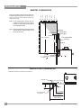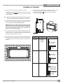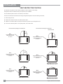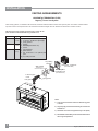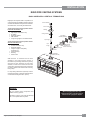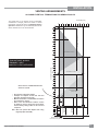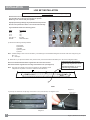
1
Regency Gem54 Gas Fireplace Owners & Installation Manual MODELS: GEM54-NG GEM54-LPG GEM54-ULPG LISTINGS AND CODE APPROVALS These gas appliances have been tested in accordance with AS4558 / NZS 5262 and have been certified by the Australian Gas Association for installation and operation as described in these Installation and Operating Instructions. Your unit should be serviced annually by an authorised service person. www.regency-fire.com.au WARNING: FOR YOUR SAFETY If the information in these instructions are not followed What to do if you smell gas: exactly, a fire or explosion may result causing property Do not try to light any appliance Do not touch any electrical switch: damage, personal injury or loss of life. do not use any phone in your FOR YOUR SAFETY building. Do not store or use gasoline or other flammable vapors and Immediately call your gas supplier liquids in the vicinity of this or any other appliance. from a neighbour's phone. Follow the gas supplier's instructions. Installation and service must be performed by a qualified If you cannot reach your gas installer, service agency or the gas supplier. supplier, call the fire department. Installer: Please complete the details on the back cover and leave this manual with the homeowner. Homeowner: Please keep these instructions for future reference. 918-784c 12/24/13 To the New Owner: Congratulations! You are the owner of a state-of-the-art Gas Fireplace by REGENCY®. The Gem54 has been designed to provide you with all the warmth and charm of a wood fireplace at the flick of a switch. The model Gem54 has been approved by AGA for both safety and efficiency. As it also bears our own mark, it promises to provide you with economy, comfort and security for many trouble free years to follow. Please take a moment now to acquaint yourself with these instructions and the many features of your Regency® Fireplace. 2 Regency Gemfire™ Gas Fireplace TABLE OF CONTENTS DATA BADGE Copy of data badge .......................................................4 DIMENSIONS Unit Dimensions ............................................................5 Faceplate & Door frame overlay Dimensions ................5 Conversion from NG to ULPG .....................................30 Aeration Adjustment ....................................................33 Wiring Diagram ...........................................................33 Reflective Panel Installation ........................................34 Glass Crystals or optional ceramic stones ..................35 Installation On Burner ..................................................35 Optional Pebble Installation for Firebox Base .............35 Log Set Installation ......................................................36 Screen & Door frame overlay Installation ....................39 Faceplate installation ...................................................40 INSTALLATION OPERATING INSTRUCTIONS Important Message ......................................................6 Before You Start ............................................................6 General Safety Information............................................6 Installation Checklist ......................................................7 Locating Your Gas Fireplace .........................................7 Clearances ....................................................................8 Non-Combustible Requirements ...................................8 Non combustible facing board .......................................9 Non combustible facing installation ...............................9 Mantel Clearances.......................................................10 Mantel Leg Clearances................................................10 Framing & Finishing..................................................... 11 Unit Assembly Prior To Installation ..............................13 Standoff Assembly ...............................................13 Nailing Strips........................................................13 Venting Introduction .....................................................13 Vent Restrictor Position ...............................................14 Exterior Flue Termination Locations ............................15 Venting Arrangements ................................................16 Horizontal Termination (Flex) ...............................16 Rigid Pipe Venting Systems ........................................17 Basic Horizontal & Vertical Terminations .............17 5” x 8” Rigid Pipe Cross Reference Chart ...................18 Venting Arrangements ................................................20 Allowable Horizontal Terminations .......................20 Venting Arrangements ................................................21 Allowable Horizontal Terminations for Gem54-lpg/ ulpg ......................................................................21 Venting Arrangements ................................................24 Allowable Vertical Terminations for Gem54-ng ....24 Venting Arrangements ................................................25 Allowable Vertical Terminations for Gem54-lpg/ ULPG ...................................................................25 Unit Installation with Horizontal Termination ................26 Unit Installation with Vertical Termination ....................27 Unit Installation ............................................................28 High Elevation .............................................................29 Gas Line Installation ....................................................29 Pilot Adjustment ...........................................................29 Gas Pipe Pressure Testing ..........................................29 S.I.T. Valve Description................................................29 Conversion from NG to LPG .......................................30 Regency Gemfire™ Gas Fireplace Operating Instructions .................................................42 First Fire ......................................................................42 Lighting Procedure ......................................................42 Shutdown Procedure ...................................................42 Normal Operating Sounds of Gas Appliances .............42 Copy of Lighting Plate Instructions ..............................43 Fan Service .................................................................44 Wiring ..........................................................................46 MAINTENANCE Maintenance Instructions.............................................47 General Vent Maintenance ..........................................47 Thermopile / Thermocouple.........................................47 Glass Gasket ...............................................................47 Glass Door...................................................................47 Glass Replacement .............................................47 Glass Door Removal ...................................................48 DC Spark Box Battery Replacement ...........................49 DC Spark Box Replacement........................................49 Valve Tray Replacement..............................................50 PARTS LIST Main Assembly ............................................................52 Accessories .................................................................53 WARRANTY Warranty ......................................................................55 3 SAFETY LABEL This is a copy of the badge that accompanies each Gem54™-NG Direct Vent Gas Fireplace. We have printed a copy of the contents here for your review. NOTE: Regency® units are constantly being improved. Check the badge on the unit and if there is a difference, the badge on the unit is the correct one. COPY OF DATA BADGE Regency Gas Fireplace Model Gas Type Model Distributed by: NG Gem54-NG LPG Gem54-LP ULPG Gem54-ULPG Gas Consumption 35.9 mj. 32.2mj. Manifold Pressure 0.88 kPa 2.49kPa 2.49 kPa Injector Size 1 x #32 1 x#51 1 x #52 2.95mm 1.70mm 1.61mm Western Australia: Air Group Australia 28 Division St Welshpool WA 6106 28.7mj. Approval No: AGA 7493 G Eastern Australia: Fireplace Products Australia Pty. Ltd. 1 Conquest Way Hallam, VIC 3803 To be installed by an authorised person in accordance with installation instructions provided with the appliance. Code AS4558 / NZ5262 N2134 Electrical: Millivolt Only Serial Number 345 918-785b DO NO T DO NO T DO NO T DO NO T DO NO T DO NO T DO NO T OPERATE THIS APPLIANCE BEFORE READING THE INSTRUCTIONS BOOKLET. PLACE ARTICLES ON OR AGAINST THIS APPLIANCE STORE CHEMICALS OR FLAMMABLE MATERIALS NEAR THIS APPLIANCE. SPRAY AEROSOLS IN THE VICINITY OF THIS APPLIANCE WHILE IN OPERATION. OPERATE WITH PANELS, COVERS OR GUARDS REMOVED FROM THIS APPLIANCE. ENCLOSE THIS APPLIANCE. MODIFY THIS APPLIANCE. 908-602a Warning primarily a decorative appliance not certified as a space heater 909-133 (Australia Only) 4 Regency Gemfire™ Gas Fireplace DIMENSIONS UNIT DIMENSIONS 52-5/8” (1337mm) 59” (1499mm) 19-3/4” (502mm) 35-1/4” (895mm) 22-3/8” (568mm) 5-11/16” (144mm) 46-3/8” (1178mm) 31-5/8” (803mm) 17-1/8” (435mm) 10-5/8” (270mm) 48-1/2” (1232mm) 1-1/2” (38mm) 20-1/2” (521mm) FACEPLATE & DOOR FRAME OVERLAY DIMENSIONS Regency Gemfire™ Gas Fireplace 5 INSTALLATION IMPORTANT MESSAGE SAVE THESE INSTRUCTIONS The Gem54™ Direct Vent Fireplace must be installed in accordance with these instructions. Carefully read all the instructions in this manual first. Consult the "authority having jurisdiction" to determine the need for a permit prior to starting the installation. It is the responsibility of the installer to ensure this fireplace is installed in compliance with manufacturers instructions and all applicable codes and complies with a S5601 / AG601 clause 5.12, 13.2 and 5.12, 13.5. BEFORE YOU START INSTALLATION AND REPAIR SHOULD BE DONE BY AN AUTHORIZED SERVICE PERSON. THE APPLIANCE SHOULD BE INSPECTED BEFORE USE AND AT LEAST ANNUALLY BY A PROFESSIONAL SERVICE PERSON. MORE FREQUENT CLEANING MAY BE REQUIRED DUE TO EXCESSIVE LINT FROM CARPETING, BEDDING MATERIAL, ETC. IT IS IMPERATIVE THAT CONTROL COMPARTMENTS, BURNERS AND CIRCULATING AIR PASSAGEWAYS OF THE APPLIANCE BE KEPT CLEAN. DUE TO HIGH TEMPERATURES, THE APPLIANCE SHOULD BE LOCATED OUT OF TRAFFIC AND AWAY FROM FURNITURE AND DRAPERIES. WARNING: FAILURE TO INSTALL THIS APPLIANCE CORRECTLY WILL VOID YOUR WARRANTY AND MAY CAUSE A SERIOUS HOUSE FIRE. CHILDREN AND ADULTS SHOULD BE ALERTED TO THE HAZARDS OF HIGH SURFACE TEMPERATURES, ESPECIALLY THE FIREPLACE GLASS, AND SHOULD STAY AWAY TO AVOID BURNS OR CLOTHING IGNITION. YOUNG CHILDREN SHOULD BE CAREFULLY SUPERVISED WHEN THEY ARE IN THE SAME ROOM AS THE APPLIANCE. 6 CLOTHING OR OTHER FLAMMABLE MATERIAL SHOULD NOT BE PLACED ON OR NEAR THE APPLIANCE. NOT INTENDED FOR FIREPLACE INSERT. 13) Do not slam shut or strike the glass door. 14) Under no circumstances should any solid fuels (wood, paper, cardboard, coal, etc.) be used in this appliance. 15) The appliance area must be kept clear and free of combustible materials, (gases and other flammable vapours and liquids). GENERAL SAFETY INFORMATION 1) The appliance installation must conform with local codes or, in the absence of local codes, with the current Installation and Building Codes. "THIS UNIT MUST ALWAYS TERMINATE / VENT DIRECTLY TO THE OUTDOORS." 2) The appliance when installed, must be electrically grounded in accordance with local codes. 3) See general construction and assembly instructions. The appliance and vent should be enclosed. 4) This appliance must be connected to the specified vent and termination cap to the outside of the building envelope. Never vent to another room or inside a building. Make sure that the vent is fitted as per Venting instructions. 5) Inspect the venting system annually for blockage and any signs of deterioration. 6) Venting terminals shall not be recessed into a wall or siding. 7) Any safety glass removed for servicing must be replaced prior to operating the appliance. 8) To prevent injury, do not allow anyone who is unfamiliar with the operation to use the fireplace. 9) Wear gloves and safety glasses for protection while doing required maintenance. 10) Be aware of electrical wiring locations in walls and ceilings when cutting holes for termination. 11) Under no circumstances should this appliance be modified. Parts that have to be removed for servicing should be replaced prior to operating this appliance. 12) Installation and any repairs to this appliance should be done by an authorized service person. A professional service person should be called to inspect this appliance annually. Make it a practice to have all of your gas appliances checked annually. Regency Gemfire™ Gas Fireplace INSTALLATION INSTALLATION CHECKLIST 1) Locate appliance a) Room location (Refer to "Locating Your Gas fireplace" section) b) Clearances to Combustibles (Refer to "Clearances" section) c) Mantle Clearances (Refer to "Mantel Clearances" section) d) Framing & Finishing Requirements (Refer to "Framing & Finishing" section) e) Venting Requirements (Refer to "Venting" section) This includes: 1) Clocking the appliance to ensure the correct firing rate (rate noted on label 41,500 Btu/h, after burning appliance for 15 minutes. 4) This appliance is Listed for bedroom installations using the standard Remote (millivolt thermostat system). Some areas may have further requirements, check local codes before installation. 2) If required, adjusting the primary air to ensure that the flame does not carbon. First allow the unit to burn for 15-20 min. to stabilize. 5) The Gem54 Direct Vent Gas Fireplace is approved for alcove installations, see "Clearances" section for details. CAUTION: Any alteration to the product that causes sooting or carboning that results in damage is not the responsibility of the manufacturer. 6) We recommend that you plan your installation on paper using exact measurements for clearances and floor protection before actually installing this appliance. Have an authorized inspector, dealer, or installer review your plans before installation. LOCATING YOUR GAS FIREPLACE Note: For vent terminations refer to "Exterior Vent Termination Locations" section. 2) Assemble the standoffs and nailing strips (Refer to "Unit Assembly Prior to Installation). 3) Slide unit into place. 4) Install vent (Refer to "Venting Arrangement" sections). 1) When selecting a location for your fireplace, ensure that the clearances are met. 5) Make gas connections (Refer to "Gas Line Installation section). 2) The appliance must be installed on a flat, solid, continuous surface For example a wood, metal or concrete floor or in a raised (on the wall) application. The appliance must be installed on a metal or wood panel extending the full width and depth of the appliance. 6) Test the pilot (Refer to "Pilot Adjustment" section). 7) Test Gas Pressure (Refer to "Gas Pipe Pressure Testing" section). 8) Install standard and optional features. Refer to the following sections: a) b) c) d) e) 3) The Gem54 Direct Vent Gas Fireplace can be installed in a recessed position or framed out into the room as in A, B, C and D. See Diagram 1. Glass Crystals Optional Firebox Base Pebbles Optional Stainless Steel Reflective Panels Faceplate / Door Frame Overlay Remote Control or Wall Thermostat 9) Wall Mounted ON/OFF Switch: Use the toggle wall switch supplied with the manual package. Use of a “decor” switch causes higher resistance which is a problem on gas fireplaces. Diagram 1 10) Final check. Before leaving this unit with the customer, the installer must ensure that the appliance is firing correctly and operation fully explained to customer. Regency Gemfire™ Gas Fireplace A) B) C) D) Flat on Wall Flat on Wall Corner Recessed into Wall/Alcove Corner 7 INSTALLATION CLEARANCES The clearances listed below are Minimum distances unless otherwise stated: A major cause of chimney related fires is failure to maintain required clearances (air space) to combustible materials. It is of the greatest importance that this fireplace and vent system be installed only in accordance with these instructions. Caution Requirements The top, back and sides of the fireplace are defined by standoffs. The metal ends of the standoff may NOT be recessed into combustible construction. Clearance: Dimension A: Mantel Height (min.) 20" (508mm) B: Sidewall C: Ceiling (room and/or alcove) WARNING Fire hazard is an extreme risk if these clearances (air space) to combustible materials are not adhered to. It is of greatest importance that this fireplace and vent system be installed only in accordance with these instructions. Measured From: Top of Fireplace Opening 4" (102mm) Side of Fireplace Opening 40-7/8" (1038mm) Top of Fireplace Opening Flue Clearances D: Mantel Depth (max.) 13" (330mm) 30" Above Fireplace Opening E: Alcove Width 83" (2108mm) Sidewall to Sidewall (Minimum) F: Alcove Depth 36" (914mm) Note 0" Horizontal - Top Horiztonal - Side Horiztonal - Bottom Vertical 3" (76mm) 2" (51mm) 2" (51mm) 2" (51mm) Front to Back Wall (Maximum) No hearth required C D F F B A B G E Installed Close to Ceiling Installed Close to Floor NON-COMBUSTIBLE REQUIREMENTS Metal Stud (header) 60-1/2" (1537mm) Wood Stud 22-1/2” 48" (1219mm) 52-5/8” Non-combustible Material Non-combustible Material Non-combustible Material 28” (711mm) 20" (508mm) Wood Stud Non-combustible Material 4" (102mm) 8 5-11/16” (144mm) Regency Gemfire™ Gas Fireplace INSTALLATION NON COMBUSTIBLE FACING BOARD 5-5/8” (143mm) 52-5/8” (1343mm) Non-combustible Facing Board 21-3/4” (554mm) Non-combustible Facing Board Non-combustible Facing Board If finishing the wall above the unit with materials such as tile, brick, marble, etc. non-combustible board available from the building supply store can be used. Timber Stud 20" (508mm) Calcium silicate board is a high - grade material with cement, quartz, natural and selected minerals as the main raw materials. It is widely used for partitions and ceilings in buildings. It is fire proof and earthquake proof. Metal Stud (header) 61-1/2" (1537mm) Timber Stud 22-3/8” (568mm) If finishing the wall above the unit with paint the non-combustible board (shipped separately from the unit) should be installed. Facing board must be ordered when ordering the unit. Non-combustible Facing Board 4" (102mm) Note: Calcium Silicate is 12mm thick. 61-1/2" (1537mm) NON COMBUSTIBLE FACING INSTALLATION Caution: This non-combustible board can be damaged if dropped or struck. Handle with care. Inspect board prior to installation. Do not install if cracked. 1) Using plaster board screws - secure non combustible material around unit, framing and top nailing strip every 150mm. Important Note: To avoid cracking the board - pre-drill holes prior to securing to unit/ framing. 2) Wipe any debris/dust from the non combustible material and drywall. 3) Prior to taping and mudding it is highly recommended to prime the facing and edges using a quality primer. This will ensure proper adhesion of both the tape and mud. The optional board is very porous. During dry fit, ensue that both surfaces being taped are even. Non- combustible board (calcium silicate) Non- combustible board (calcium silicate) 4) Tape the seams using a mesh type tape. 5) To seal up seams as normal we recommend using a product called Durabond high strength compound - for the first coat This product can be found at any hardware store. Sealant must be cured as per manufacturer’s recommendations. 6) Prime wall for a second time for proper adhesion of paint 7) Paint walls using a high quality paint which will withstand the high temperatures being emitted from this appliance. Note: Incorrectly sealed joints may crack. Keep sealant thickness to a minimum. Regency Gemfire™ Gas Fireplace Non-combustible board MUST BE PRIMED. 9 INSTALLATION (152mm) (102mm) (51mm) 2 (254mm) 4 (305mm) 6 (356mm) 14 12 10 8 Note: A non-combustible mantel may be installed at a lower height if the framing is made of metal studs covered with a non-combustible board. 0 Due to the extreme heat this fireplace emits, the mantel clearances are critical. Combustible mantel clearances from top of front facing are shown in the diagram on the right. (203mm) MANTEL CLEARANCES 13" (330mm) Note: Ensure the paint that is used on the mantel and the facing is "heat resistant" or the paint may discolour. 3 ½" (89mm) Drywall Metal Stud (On Edge) 1" (25mm) 30” (762mm) Non-combustible Facing 21” Standoff 20” 0 Top of 28-1/8” Fireplace (724mm) Opening To Floor MANTEL LEG CLEARANCES Combustible mantel leg clearances as per diagram: MANTEL LEG 4”(102mm) Non-Combustible 4" 1.5" (38mm) Allowable mantel leg projection 11-1/2” (292mm) 14” (356mm) 15-3/4” (400mm) 10 Regency Gemfire™ Gas Fireplace INSTALLATION FRAMING & FINISHING 1) Frame in the enclosure for the unit with framing material. IMPORTANT: Header must be metal stud. All other framing may be of combustible type such as 2x4 (0.6m x 1.2m) / 2x6 (0.6m x 1.8m) framing materials. 5) When finishing around the faceplate, if material such as brick, stone, etc. extend past the faceplate depth - the minimum opening dimensions noted below must be adhered to, this is to assure removal of the faceplate. Note: When constructing the framed opening, please ensure there is access to install the gas lines when the unit is installed. 2) For exterior walls, insulate the enclosure to the same degree as the rest of the house, apply vapour barrier and drywall, as per local installation codes. (Do not insulate the fireplace itself.) Nailing strip/ Standoff bracket WARNING: Failure to insulate and add vapor barriers to the inside of the exterior wall will result in operational and performance problems including, but not limited to: excessive condensation on glass doors, poor flame package, carbon, blue flames etc. These are not product related issues. 3) The unit does not have to be completely enclosed in a chase. You must maintain clearances from the vent to combustible materials: See "Clearances" section. Combustible materials can be laid against the side and back standoffs and the stove base. 4) If material such as brick, stone, etc extends past the faceplate depth, when finishing around the faceplate, the minimum opening dimensions noted below must be adhered to ensuring for the removal of the faceplate. Nailing Strips Finished Material Nailing Strip Position 13mm 25mm Factory Setting Nailing Strip 1” Forward 58-3/16” (1478mm) 26-5/8” (676mm) Unit 25mm 13mm Nailing Strip ½” Forward Unit 38mm 0mm (flush) Nailing Strip Flush w/unit Factory Set Unit Regency Gemfire™ Gas Fireplace 11 INSTALLATION Framing Dimensions Description A B Framing Height Framing Width 46-5/8” (1184mm) 60” (1524mm) C* D E F G H I J K L Framing Depth* Minimum Height to Combustibles Corner Wall Length Corner Facing Wall Width Vent Centerline Height Non-combustible facing height Gas Connection Opening Height Gas Connection Height Gas Connection Inset Gas Connection Opening Width 51” (1295mm) 72" (1829mm) 101-7/8 (2586mm) 44” (1118mm) 20” (508mm) 1-1/2” (38mm) 4” (102mm) 7-1/4” (184mm) 3-1/4” (83mm) Gem54 22” (559mm) * Framing depth measurement is noted with the side nailing strips set as far forward on the firebox as possible. The nailing strips can be adjusted back - up to 1” (25mm) to allow for varying thicknesses in non-combustible material & wall finishes. D Metal Stud (Header) on edge A H Metal Stud (Header) on edge Non-Combustible Facing B G C E I J K L F 12 (Located on the right side of the fireplace) Regency Gemfire™ Gas Fireplace INSTALLATION NAILING STRIPS UNIT ASSEMBLY PRIOR TO INSTALLATION The Top Standoff/ Nailing Strip, side nailing strips and standoffs must be correctly positioned and attached to the unit before sliding the unit into position. The nailing strips come attached to the unit. There is 1 plate on each side,1 on the top, and one on the bottom that can be folded out as required. The top and side nailing strips are secured to the framing. The bottom nailing strip is secured to the unfinished floor - if installing the unit directly on the floor. Note: The bottom nailing strip will need to be bent on site and adjusted to accommodate the thickness of the facing material. STANDOFF ASSEMBLY The side, rear and bottom standoffs are shipped in a flat position and must be folded into shape and attached - see diagram 1. Standoff 1) Remove the standoffs from the unit. Nailing Strip / Top Standoff Bracket 2) Take each standoff and bend into the correct shape. Bend up at the bend lines until the screw holes in the standoff and the pre-punched screw holes on the unit line up. Standoff Rear/side standoffs Diagram 1 The top stand off / nailing strip is shipped attached to the back of the unit as shown below. 1) Remove one screw in location shown below. Replace the screw on the back the unit after removing the standoff / nailing strip. 2) Bend the 3 tabs at the bottom of the stand off / nailing strip to 90°, bend in the same direction as the top tabs. 3) Install on the top front of the unit as shown in diagram 3. Do not fully tighten the screws when installing - until the facing thickness has been determined. Nailing Strips Diagram 3 IMPORTANT NOTE Framing depth measurement is noted with the side nailing strips set as far forward on the firebox as possible. The nailing strips can be adjusted back up to 1” to allow for varying thicknesses in non-combustible material & wall finishes. VENTING INTRODUCTION The Gem54™ uses the "balanced flue" technology Co Axial system. The inner liner vents products of combustion to the outside while the outer liner draws outside combustion air into the combustion chamber thereby eliminating the need to use heated room air for combustion and losing warm room air up the chimney. Note: These flue pipes must not be connected to any other appliance. The gas appliance and vent system must be vented directly to the outside of the building, and never be attached to a chimney serving a separate solid fuel or gas burning appliance. Each direct vent gas appliance must use it's own separate vent system. Common vent systems are prohibited. Standoff Remove this screw to release top standoff / nailing strip Standoff Regency Gemfire™ Gas Fireplace Diagram 2 13 INSTALLATION VENT RESTRICTOR POSITION Vent restriction is required for certain venting installations, see the diagrams in the "Venting Arrangements" section to determine if they are required for your installation. The Vent Restrictor plate is located on the inside top of the firebox. To set the vent restriction as indicated in the venting arrangements diagrams, refer to the following instructions; 1) Remove the glass door. 2) Remove the screws that hold the vent restrictor plate in place. 3) Adjust the vent restrictor plate to the required vent restrictor position as per the diagrams shown. 4) Once the vent restrictor plate is in the required position, secure with screws. Vent Restrictor Settings for Gem54-NG Vent Restrictor Settings for Gem54-LP Gem54-ULPG SET 1 THIS HOLE SETS THE VENT RESTRICTOR AT 108mm 108mm SET 1 THIS HOLE SETS THE VENT RESTRICTOR AT 108mm Vent Restrictor Set 1 76mm SET 2 THIS HOLE SETS THE VENT RESTRICTOR AT 76mm SET 3 THIS HOLE SETS THE VENT RESTRICTOR AT 51mm Vent Restrictor Set 2 51mm SET 3 THIS HOLE SETS THE VENT RESTRICTOR AT 51mm SET 4 THIS HOLE SETS THE VENT RESTRICTOR AT 25mm Vent Restrictor Set 3 14 Regency Gemfire™ Gas Fireplace INSTALLATION EXTERIOR FLUE TERMINATION LOCATIONS Minimum clearances required for balanced flue terminals or the flue terminals of outdoor appliances according to AS5601-2004 (AGA gas installation code) or NZS 5262 (New Zealand) and local authorities having jurisdiction. a b c d e f g h j k Minimum Clearance (mm) Below eaves, balconies or other projections: - Appliances up to 50 MJ/h input 300 - Appliances over 50 MJ/h input 500 From the ground or above a balcony 300 From a return wall or external corner 500 From a gas meter (M) 1000 From an electricity meter or fuse box (P) 500 From a drain or soil pipe 150 Horizontal from any building structure (unless appliance is approved for closer installation) or obstruction facing a terminal 500 From any other flue terminal, cowl or combustion air intake 500 Horizontally from an openable window, door, or non-mechanical air inlet, or any other opening into a building, with the exception of sub-floor ventilation (see also Note (I)): - Appliances up to 150 MJ/h input 500 - Appliances over 150 MJ/h input 1500 Vertically below an openable window, door, or non-mechanical air inlet, or any other opening into a building, with the exception of sub-floor ventilation (see also Note (I)): see table below Clearance 'k' in mm Space Heaters Up to 50 MJ/h All Other Appliances Up to 50 MJ/h input 150 Over 50 MJ/h input Over 150 MJ/h to 150 MJ/h input 500 1000 input 1500 (I) For mechanical air inlets, including spa blowers, the clearance 'j' and 'k' shall be 1500 mm in all cases. (II) All distances shall be measured vertically or horizontally along the wall to a point in line with the nearest par to of the terminal. (III) Prohibited area below electricity meter or fuse box extends to ground level. (IV) A flue terminal of this type shall not be located under a roofed area unless the roofed area is fully open on at least two sides and a free flow of air at the appliance is achieved. Regency Gemfire™ Gas Fireplace 15 INSTALLATION VENTING ARRANGEMENTS HORIZONTAL TERMINATION (FLEX) Regency® Direct Vent System These venting systems, in combination with the Gem54, have been tested and listed as a direct vent system by AGA. The location of the termination cap must conform to the requirements in the Vent Terminal Locations diagram from the "Exterior Vent Termination Locations" section. FPI Direct Vent (Flex) System Termination Kits include all the parts needed to install the Gem54 using a flexible vent. FPI Kit # Length Contains: #946-615 4 Feet 1) 8” (203mm) flexible liner (Kit length) 5”(127mm) flexible liner (Kit length) 3) spring spacers 6 Feet 4) thimble (1.8 m) 5) AstroCap termination cap 6) screws 7) tube of Mill Pac 10 Feet 8) plated screws (3 m ) 9) S.S. screws #8 x 1-1/2” (38mm) drill point 10) vinyl siding standoff (1.2 m) 2) #946-618 #946-616 Vinyl Siding Standoff Vent Guard - if required* (Part #946-506/P) Wall Thimble (Mandatory in all Horizontal Terminations) TM AstroCap XL Termination Cap (Part #946-623/P) 5” dia. flue pipe 8” dia. Flue pipe spring spacer Notes: 1) Liner sections should be continuous without any joints or seams. 2) Only Flex pipe purchased from FPI may be used for Flex installations. 3) Horizontal vent must be supported every 3 feet (0.9m). 4) A wall thimble is mandatory for all horizontal terminations due to high temperatures. 16 Regency Gemfire™ Gas Fireplace INSTALLATION RIGID PIPE VENTING SYSTEMS BASIC HORIZONTAL & VERTICAL TERMINATIONS Rigid Pipe Vent Systems offer a complete line of component parts for installation of both horizontal and vertical installations. Many items are offered in decorative black, as well as galvanized finish. The minimum components required for a basic Horizontal Termination are: 1 1 1 1 1 AstroCap XL Termination Cap 90o Elbow Rigid Pipe Adaptor Wall Thimble Length of rigid pipe to suit wall thickness Vertical Terminal Storm Collar Flashing Ceiling Firestop Vinyl Siding Standoff (Optional) Pipe Length AstroCap XL Termination Cap (Part #946-623/P) The minimum components required for a basic Vertical Termination are: 1 1 1 1 1 1 Vertical Termination Cap Rigid Pipe Adaptor Lengths of pipe to adequately penetrate roof Ceiling Firestop Flashing Storm Collar Vent Guard - if required* (Part #946-506/P) Pipe Length Wall Thimble (Mandatory in all Horizontal Terminations) Pipe Length 90o Elbow Rigid Pipe Adaptor (770-994) Wall thickness is measured from the back standoffs to the inside mounting surface of termination cap. For siding other than vinyl furring strips may be used, instead of the vinyl siding standoff, to create a level surface to mount the vent terminal. The Terminal must not be recessed into siding. Measure the wall thickness including furring strips. If a Vinyl Siding Standoff is required (it must be used with vinyl siding), measure to outside surface of wall without siding and add 2" (51mm). WARNING: Do not combine venting components from different venting systems. Exception: However, use of the the AstroCap XLTM is acceptable with all systems. Regency Gemfire™ Gas Fireplace When using Rigid Vent other than Simpson Dura-Vent, 3 screws must be used to secure rigid pipe to adaptor. 17 INSTALLATION 5” X 8” RIGID PIPE CROSS REFERENCE CHART Components from different Manufacturers may not be mixed. Not All Rigid Pipe components are available directly from FPI. Description 18 Simpson Selkirk Direct Vent Pro® Direct Temp™ 6” Pipe Length-Galvanized 58DVA-06 5DT-6 6” Pipe Length-Black 58DVA-06B 5DT-6B 9” Pipe Length-Galvanized 58DVA-09 5DT-9 9” Pipe Length-Black 58DVA-09B 5DT-9B 12” Pipe Length-Galvanized 58DVA-12 5DT-12 12” Pipe Length-Black 58DVA-12B 5DT-12B 18” Pipe Length-Galvanized 58DVA-18 5DT-18 18” Pipe Length-Black 58DVA-18B - N/A from FPI 5DT-18B 24” Pipe Length-Galvanized 58DVA-24 5DT-24 24” Pipe Length-Black 58DVA-24B 5DT-24B 36” Pipe Length-Galvanized 58DVA-36 5DT-36 36” Pipe Length-Black 58DVA-36B 5DT-36B 48” Pipe Length-Galvanized 58DVA-48 5DT-48 48” Pipe Length-Black 58DVA-48B 5DT-48B 60” Pipe Length-Galvanized 58DVA-60 N/A 60” Pipe Length-Black 58DVA-60B - N/A from FPI N/A Adjustable Length 3”-10”-Galvanized N/A N/A Adjustable Length 3”-10”-Black N/A N/A Adjustable Length 11”-14” -Galvanized Disc. - See 58DV-08A 5DT-AJ Adjustable Length 11”-14” -Black Disc. - See 58DV-08B 5DT-AJB Extension Pipe 17”-24” -Galvanized Disc. - See 58DV-16A N/A Extension Pipe 17”-24” -Black Disc. - See 58DV-16AB N/A Adjustable Length 8-1/2”-Galvanized 58DVA-08A - N/A from FPI N/A Adjustable Length 8-1/2”-Black 58DVA-08AB N/A Extension Pipe 16”-Galvanized 58DVA-16A - N/A from FPI N/A Extension Pipe 16”-Black 46DVA-16AB N/A 45º Elbow-Galvanized 58DVA-E45 5DT-EL45 45º Elbow-Black 58DVA-E45B 5DT-EL45B 45º Elbow Swivel-Galvanized Disc. - See 58DVA-E45 N/A 45º Elbow Swivel-Black Disc.-See 58DVA-E45B N/A 90º Elbow-Galvanized 58DVA-E90 5DT-EL90S 90º Elbow-Black 58DVA-E90B 5DT-EL90SB 90º Elbow, Swivel-Galvanized Disc. - See 46DVA-E45 N/A 90º Elbow, Swivel-Black Disc. - See 46DVA-E45 N/A 90º Starter Elbow, Swivel-Galvanized N/A N/A Adaptor* N/A N/A Ceiling Support 58DVA-DC 5DT-CS Cathedral Support Box 58DVA-CS 5DT-CSS Wall Support/Band 58DVA-WS 5DT-WS/B Offset Support 58DVA-ES - N/A from FPI 5DT-OS Wall Thimble-Black 58DVA-WT 5DT-WT Wall Thimble Support/Ceiling Support 58DVA-DC - N/A from FPI N/A Firestop Spacer 58DVA-FS 5DT-FS Trim Plate-Black 58DAV-WFS 5DT-TP Regency Gemfire™ Gas Fireplace INSTALLATION Description Attic Insulation Shield 12” Simpson Selkirk Metal-Fab™ ICC Excel Direct Vent Pro® Direct Temp™ Sure Seal Direct 58DVA-IS N/A from FPI N/A N/A N/A Basic Horizontal Termination Kit (A) N/A 5DT-HKA N/A N/A Horizontal Termination Kit (B) 58DVA-KHA 5DT-HKB N/A N/A Vertical Termination Kit 58DVA-VHA 5DT-VKC N/A N/A High Wind Vertical Cap 58DVA-VCH N/A N/A TM-5VT High Wind Horizontal Cap N/A N/A N/A TM-5DHT Horizontal Square Termination Cap N/A 5DT-HHC 5DHT TM-5HT Vertical Termination Cap N/A 5DT-HVC 5DVT TM-5VT Storm Collar 58DVA-SC 5DT-SC 5DSC TM-SC Adjustable Flashing 0/12-6/12 58DVA-F6 5DT-AF6 5DF TF-5FA Adjustable Flashing 6/12-12/12 58DVA-F12 5DT-AF12 5DF1-2 TF-5FB Vinyl Siding Standoff 58DVA-VSS 5DT-VS 5DVS TM-VSS Vinyl Siding Shield Plate N/A 5DT-VSP N/A N/A Snorkel Termination 14” 58DVA-SNK14 N/A N/A TM-5ST14 Snorkel Termination 36” 58DVA-SNK36 (N/A - FPI) N/A N/A TM-5ST36 Restrictor Disk 58DVA-RD N/A N/A TM-5DS Colinear Flex Connectors N/A N/A N/A N/A FPI 946-604/P Simpson Direct Vent -Vent Guard (Optional) 946-623/P 770-994 Rigid Pipe Adaptor (Must use with all rigid piping) 946-506/P AstroCap XL Horizontal Cap Vent Guard (Optional) 946-606 Starter collar reducer 5” x 8” to 4” x 6-5/8” 946-625 Vinyl Siding Standoff - AstroCap XL Note: When using Metal-Fab Sure Seal Rigid Piping - please note that the Adaptor (4DDA) must be used in conjunction with FPI Rigid Pipe Adaptor (510-994). Offset Pipe Selection: Use this table to determine offset pipe lengths. Pipe Length (L) 5” x 8” Venting Run (X) Rise (Y) For specific instructions on venting components - visit the manufacturers website listed below. 0” (0mm) 5-11/16” (144mm) 15-5/16” (389mm) Simpson Direct Vent Pro: www.duravent.com 6” (152mm) 8-13/16” (224mm) 18-7/16” (468mm) Selkirk Direct-Temp: www.selkirkcorp.com 9” (229mm) 10-15/16” (278mm) 20-9/16” (522mm) Metal-Fab Sure Seal: www.mtlfab.com 12” (305mm) 13” (330mm) 22-11/16” (576mm) Industrial Chimney Company: www.icc-rsf.com 24” (610mm) 21-7/16” (697mm) 31-1/16” (789mm) 36” (914mm) 29-13/16” (757mm) 39-7/16” (1002mm) 48” (1219mm) 38-1/4” (972mm) 47-7/8” (1216mm) Note: Horizontal runs of vent must be level, or have a 1/4” rise for every 1 foot of run towards the termination. Never allow the vent to run downward - this could cause high temperatures and may present a possible fire hazard. Regency Gemfire™ Gas Fireplace 19 INSTALLATION VENTING ARRANGEMENTS ALLOWABLE HORIZONTAL TERMINATIONS The diagram shows all allowable combinations of vertical runs with horizontal terminations, using one 90o (two 45o elbows equal one 90o elbow). Note: Must use optional rigid pipe adapter (Part# 770-994) when using Simpson Duravent Venting Systems. Horizontal (Feet) 0 2 4 6 8 10 14 12 16 18 20 18 Vent Restrictor on Set 3 16 Vertical Height (Feet) 14 Vent Restrictor on Set 2 12 10 Vent Restrictor on Set 1 (factory setting) 8 6 4 2 44” (1118mm) Minimum Height Requirement "THIS UNIT MUST ALWAYS TERMINATE / VENT DIRECTLY TO THE OUTDOORS." 0 VENT RESTRICTOR SETTING: Vent restrictor factory set, no adjustment required unless otherwise indicated. Refer to the "Vent Restrictor Position" section for details on how to change the vent restrictor from the factory setting of Set 1 to Set 2 or Set 3 if required. • • • • 20 Maintain clearances to combustibles as listed in "Clearances" section Horizontal vent must be supported every 3 ft / 91 cm. Firestops are required at each floor level and whenever passing through a wall. A wall thimble is mandatory for all horizontal terminations due to high temperatures. Regency Gemfire™ Gas Fireplace INSTALLATION VENTING ARRANGEMENTS ALLOWABLE HORIZONTAL TERMINATIONS FOR GEM54-LPG/ULPG The diagram shows all allowable combinations of vertical runs with horizontal terminations, using one 90o (two 45o elbows equal one 90o elbow). Note: Must use optional rigid pipe adapter (Part# 770-994) when using Rigid Pipe Venting Systems. Horizontal (Feet) 0 2 4 6 8 10 14 12 16 18 20 18 16 Vertical Height (Feet) 14 Vent Restrictor on Set 3 12 10 Vent Restrictor on Set 1 (factory setting) 8 6 4 2 44” (1118mm) Minimum Height Requirement "THIS UNIT MUST ALWAYS TERMINATE / VENT DIRECTLY TO THE OUTDOORS." 0 VENT RESTRICTOR SETTING: Vent restrictor factory set, no adjustment required unless otherwise indicated. Refer to the "Vent Restrictor Position" section for details on how to change the vent restrictor from the factory setting of Set 1 to Set 3 if required. Note: Regency® Direct Vent System (Flex) is only approved for horizontal terminations. • • • • Maintain clearances to combustibles as listed in "Clearances" section Horizontal vent must be supported every 3 feet (0.9m). Firestops are required at each floor level and whenever passing through a wall. A wall thimble is mandatory for all horizontal terminations due to high temperatures. Regency Gemfire™ Gas Fireplace 21 INSTALLATION Horizontal Venting with Two (2) 90o Elbows H1 o H o One 90 elbow = Two 45 elbows. Option A) V .6m Min. V H + H1 1.2m Max. B) .9m Max. 1.8m Max. C) 1.2m Max. 2.4m Max. D) 1.5m Max. 2.7m Max. E) 1.8m Max. 3m Max. With these options, maximum total pipe length is 9m with minimum of 1.8m total vertical and maximum 3m total horizontal. Please note minimum .3m between 90 o elbows is required. VENT RESTRICTOR SETTING: Vent restrictor factory set at Set 1, no adjustment required. Horizontal Venting with Three (3) 90o Elbows H1 H V1 V One 90o elbow = Two 45o elbows. Option V H V+ V1 H+ H1 A) .6m Min. .3m Max. .9m Min. .6m Max. B) .6m Min. .6m Max. 1.5m Min 1.2m Max. C) .9m Min. .6m Max. 2.1m Min. 1.5m Max. D) 1.2m Min. .9m Max. 2.7m Min. 1.8m Max. E) 1.5m Min. 1.2m Max. 3m Min. 2.1m Max. F) 1.8m Min. 1.8m Max. 3.3m Min 2.7m Max. With these options, max. total pipe length is 9m with min. of 3.4m total vertical and max. 2.7m total horizontal. Please note minimum .3m between 90o elbows is required. VENT RESTRICTOR SETTING: Vent restrictor factory set at Set 1, no adjustment required. 22 Regency Gemfire™ Gas Fireplace INSTALLATION Vertical Venting with Three (3) 90o Elbows One 90o elbow = Two 45o elbows. Option V H V+ V1 A) .6m Min. .6m Max. 1.2m Min. B) .9m Min. 1.2m Max. 1.8m Min C) 1.2m Min. 1.5m Max. 2.1m Min. D) 1.5m Min. 1.8m Max. 2.4m Min. E) 1.8m Min. 2.4m Max. 2.7m Min. With these options, max. total pipe length is 9m with min. of 2.7m total vertical and max. 2.4m total horizontal. Please note minimum .3m between 90o elbows is required. VENT RESTRICTOR SETTING: Vent restrictor factory set at Set 1, no adjustment required. Regency Gemfire™ Gas Fireplace 23 INSTALLATION VENTING ARRANGEMENTS ALLOWABLE VERTICAL TERMINATIONS FOR GEM54-NG Horizontal (Feet) The shaded area in the diagram shows all allowable combinations of straight vertical and offset to vertical terminations, using two 90o elbows, with Rigid Pipe Venting Systems for Natural Gas. Two 45o elbows equal to one 90o elbow. Maximum of four 45o elbows allowed. 0 2 4 6 8 10 12 14 16 18 40 Maximum: 40 ft. (12.2m) 38 36 34 32 30 Vent Restrictor on Set 3 28 26 24 22 Vent Restrictor on Set 2 20 Maximum: 27 ft. (8.2m) Vertical Height (Feet) "THIS UNIT MUST ALWAYS TERMINATE / VENT DIRECTLY TO THE OUTDOORS." 18 16 14 Please note min. 0.3m between 90o elbows is required. 12 • Note: Must use optional flue adaptor when using Rigid Pipe (Part # 770-994). Vent Restrictor on Set 1 (factory setting) 10 8 6 4 2 Minimum 8’6” (2.6m) • Vent must be supported at offsets. Firestops are required at each floor level and whenever passing through a wall. Maintain clearances to combustibles as listed in the "Clearances" section. Refer to the "Vent Restrictor Position" section for details on how to change the vent restrictor from the factory setting of Set 1 to Set 2 or Set 3 if required. Min. 44” (1118mm) • • 0 Minimum length of pipe between elbows 12” (305mm) 24 Max. 10’ (3m)(centerline to centerline) Regency Gemfire™ Gas Fireplace 20 INSTALLATION VENTING ARRANGEMENTS ALLOWABLE VERTICAL TERMINATIONS FOR GEM54-LPG/ULPG Horizontal (Feet) The shaded area in the diagram shows all allowable combinations of straight vertical and offset to vertical terminations, using two 90o elbows, with Rigid Pipe Venting Systems for Natural Gas. Two 45o elbows equal to one 90o elbow. Maximum of four 45o elbows allowed. 0 2 4 6 8 10 12 14 16 40 Maximum: 40 ft. (12.2m) 38 36 34 32 30 Vent Restrictor on Set 4 28 26 "THIS UNIT MUST ALWAYS TERMINATE / VENT DIRECTLY TO THE OUTDOORS." 24 Vent Restrictor on Set 3 20 18 16 Maximum: 27 ft. (8.2m) Vertical Height (Feet) 22 14 Please note min. 1 ft/305mm between 90o elbows is required. 12 Vent Restrictor on Set 1 (factory setting) 10 • Note: Must use optional flue adaptor when using Rigid Pipe (Part # 770-994). 8 6 4 2 Minimum 8’6” (2.6m) • Vent must be supported at offsets. Firestops are required at each floor level and whenever passing through a wall. Maintain clearances to combustibles as listed in the "Clearances" section. Refer to the "Vent Restrictor Position" section for details on how to change the vent restrictor from the factory setting of Set 1 to Set 3 or Set 4 if required. Min. 44” (1118mm) • • 0 Minimum length of pipe between elbows 12” (305mm) Regency Gemfire™ Gas Fireplace Max. 10’ (3m)(centerline to centerline) 25 18 INSTALLATION 7) Ensure that the pipe clearances to combustible materials are maintained (Diagram 3). Install the termination cap. UNIT INSTALLATION WITH HORIZONTAL TERMINATION Note: If installing termination on a vinyl siding covered wall, a vinyl siding standoff or furring strips must be used to ensure that the termination is not recessed into the siding. (Rigid Vent Systems) Diagram 1 A top clearance of 3"(76mm) and side & bottom clearance of 2"(51mm) must be maintained; except when passing through a wall, ceiling, or at the termination where the use of a firestop or wall thimble reduces the required clearance to 1-1/2" (38mm). We recommend framing a 11"(279mm) x 11"(279mm) (inside dimensions) hole to give structural rigidity for mounting the termination. Install the vent system according to the manufacturer's instructions included with the components. 1) Set the unit in its desired location. Check to determine if wall studs or roof rafters are in the way when the venting system is attached. If this is the case, you may want to adjust the location of the unit. Rough in the gas preferably on the right side of the unit. Horizontal runs of vent must be supported every 3 feet (0.9meter). Wall straps are available for this purpose. 6) Mark the wall for a 11" x 11" (279mm x 279mm) square hole. The center of the square hole should line up with the centerline of the horizontal pipe. Cut and frame the 11 inch (279mm) square hole in the exterior wall where the vent will be terminated. See diagram 2 for center line requirements. If the wall being penetrated is constructed of non-combustible material, i.e. masonry block or concrete, an 8" (203mm) diameter hole is acceptable. 2) Direct Vent pipe and fittings are designed with special twist-lock connections to connect the venting system to the appliance flue outlet. A twist-lock appliance adaptor is required. The four wood screws provided should be replaced with appropriate fasteners for stucco, brick, concrete, or other types of sidings. 3) In conjunction with the Simpson Direct Vent Pro system, install the adaptor after the unit is set in its desired location. Put a bead of high temperature silicone inside the outer section of the adapter and a bead of Mill Pack on the inner collar. Slip the adapter over the existing inner and outer flue collar. Fasten to the outer collar only with the 3 supplied screws (drilling pilot holes will make this easier). 8) Before connecting the horizontal run of vent pipe to the vent termination, slide the Wall Thimble over the vent pipe. The wall thimble is required for all horizontal terminations. 4) Level the fireplace and fasten it to the framing using nails or screws through the top and side nailing strips. 5) Assemble the desired combination of pipe and elbows to the appliance adaptor and twist-lock for a solid connection. Note: For best results and optimum performance with each approved venting system, it is highly recommended to apply “Mill-Pac” sealant (supplied) to every inner pipe connection. Failure to do so may result in drafting or performance issues not covered under warranty. Silicone (red RTV) is optional. "THIS UNIT MUST ALWAYS TERMINATE / VENT DIRECTLY TO THE OUTDOORS." 26 Diagram 3 Diagram 2 Note: a) The horizontal run of vent must be level, or have a 1/4"/6mm rise for every 1 ft/305mm of run towards the termination. Never allow the vent to run downward. This could cause high temperatures and may present the possibility of a fire. b) The location of the horizontal vent termination on an exterior wall must meet all local and national building codes, and must not be blocked or obstructed. See "Exterior Vent Termination Locations" section for more details. 9) Slide the appliance and vent assembly towards the wall carefully inserting the vent pipe into the vent cap assembly. It is important that the vent pipe extends into the vent cap sufficient distance so as to result in a minimum pipe overlap of 1-1/4 inches (32mm). Secure the connection between the vent pipe and the vent cap. 10) Install wall thimble in the center of the 11" (279mm) square and attach with wood screws (Diagram 4). Diagram 4 Regency Gemfire™ Gas Fireplace INSTALLATION UNIT INSTALLATION WITH VERTICAL TERMINATION (Rigid Vent Systems) Note: A clearance of 2"(51mm) must be maintained; except when passing through a wall, ceiling, or at the termination where the use of a firestop or wall thimble reduces the required clearance to 1-1/2" (38mm). We recommend framing a 11"(279mm) x 11"(279mm) (inside dimensions) hole to give structural rigidity for mounting the termination. 1) Maintain the 1-1/2" (38mm) clearances (air spaces) to combustibles when passing through ceilings, walls, roofs, enclosures, attic rafter, or other nearby combustible surfaces, ensuring that the use of a firestop or wall thimble is used as noted above. Do not pack air spaces with insulation. Check " Ve n t i n g A r r a n g e m n t - Vertical Termination" section for the maximum vertical rise of the venting system and the maximum h o r i z o n t a l o ff s e t limitations. 5) Cut a hole in the roof centered on the small drilled hole placed in the roof in Step 2. The hole should be of sufficient size to meet the minimum requirements for clearance to combustibles of 1-1/2"(38mm). Slip the flashing under the shingles (shingles should overlap half the flashing) as per Diagram 4. Diagram 1 2) Set the gas appliance in its desired location. Drop a plumb bob down from the ceiling to the position of the appliance flue exit, and mark the location where the vent will penetrate the ceiling. Drill a small hole at his point. Next, drop a plumb bob from the roof to the hole Diagram 2 previously drilled in the ceiling, and mark the spot where the vent will penetrate the roof. Determine if ceiling joists, roof rafters or other framing will obstruct the venting system. You may wish to relocate the appliance or to offset, as shown in Diagram 2 to avoid cutting load bearing members. 3) A Firestop spacer must be installed in the floor or ceiling of every level. Diagram 3 Regency Gemfire™ Gas Fireplace 4) Assemble the desired lengths of pipe and elbows. Ensure that all pipes and elbow connections are in the fully twist-locked position and sealed. Note: For best results and optimum performance with each approved venting system, it is highly recommended to apply “Mill-Pac” sealant (supplied) to every inner pipe connection. Failure to do so may result in drafting or performance issues not covered under warranty. Silicone (red RTV) is optional. Diagram 5 Roof Pitch Minimum Vent Height Feet Meters flat to 7/12 2 0.61 over 7/12 to 8/12 2 0.61 over 8/12 to 9/12 2 0.61 over 9/12 to 10/12 2.5 0.76 over 10/12 to 11/12 3.25 0.99 over 11/12 to 12/12 4 1.22 over 12/12 to 14/12 5 1.52 over 14/12 to 16/12 6 1.83 over 16/12 to 18/12 7 2.13 over 18/12 to 20/12 7.5 2.29 over 20/12 to 21/12 8 2.44 A poor draft, or down drafting can result from high wind conditions near big trees or adjoining roof lines, in these cases, increasing the vent height may solve the problem. 7) Ensure vent is vertical and secure the base of the flashing to the roof with roofing rails, slide storm collar over the pipe section and seal with a mastic. 8) Install the vertical termination cap by twistlocking it. Diagram 4: The upper half of the flashing is installed under the roofing material and not nailed down until the chimney is installed. This allows for small adjustments. 6) Continue to assemble pipe lengths. Note: Any closets or storage spaces, which the vent passes through must be enclosed. Offset Chart Note: If an offset is necessary in the attic to avoid obstructions, it is important to support the vent pipe every 3 feet (0.9 meter), to avoid excessive stress on the elbows, and possible separation. Wall straps are available for this purpose (Diagram 2). Galvanized pipe is desirable above the roofline due to its higher corrosion resistance. Continue to add pipe sections through the flashing until the height of the vent cap meets the minimum height requirements specified in Diagram 5 or local codes. Note that for steep roof pitches, the vertical height must be increased. "THIS UNIT MUST ALWAYS TERMINATE / VENT DIRECTLY TO THE OUTDOORS." 27 INSTALLATION UNIT INSTALLATION (With Horizontal Termination Flex System) Note: A top clearance of 3"(76mm) and side & bottom clearance of 2"(51mm) must be maintained; except when passing through a wall, ceiling, or at the termination where the use of a firestop or wall thimble reduces the required clearance to 1-1/2" (38mm). We recommend framing a 11"(279mm) x 11"(279mm) (inside dimensions) hole to give structural rigidity for mounting the termination. 1) Locate the unit in the framing, rough in the gas (preferably on the right side of the unit). Locate the centerline of the termination and mark wall accordingly. Cut an 11"(279mm) hole in the wall (inside dimension). 4) Separate the 2 halves of the wall thimble and securely fasten the one with the tabs to the outside wall making sure that the tabs are on top and bottom. Fasten the other thimble half to the inside wall. The thimble halves slip inside each other and can be adjusted for 2 x 4 or 2 x 6 walls. 5) Slip the assembled liner and termination assembly through the thimble making sure the termination cap faces up (there are markings on the cap that show which way is up). This will position the termination cap with proper down slope for draining water. Fasten the cap to the outer wall with the 4 supplied screws. IMPORTANT: Do not locate termination hood where excessive snow or ice buildup may occur. Be sure to check vent termination area after snow falls, and clear to prevent accidental blockage of venting system. When using snow blowers, make sure snow is not directed towards vent termination area. ASTROCAP XL DIMENSIONS (946-623/P) 6) Pull the centre 5"(127mm) liner and outer 8"(203mm) liner out enough to slip over the flue collars of the fireplace. (You may wish to cut the liner shorter to make it more workable.) Do not bend liner more than 90o. The liners must slip over the collars a minimum of 1-3/8". 7) Apply Mill Pac over the fireplace inner collar and slip the 5"(127mm) liner down over it and attach with 3 supplied screws. 8) Do the same with the 8"(203mm) liner. Note: If installing termination on a siding covered wall, a vinyl siding standoff or vinyl furring strips must be used to ensure that the termination is not recessed into the siding. 2) Level the fireplace and fasten it to the framing using nails or screws through the nailing strips. 3) Assemble the vent assembly by applying Mill Pac to the 5"(127mm) inner collar of the termination and slipping the 5"(127mm) liner over it at least 1-3/8" (35mm). Fasten with the 3 screws (drilling pilot holes will make this easier). Apply Mill Pac or high temperature silicone to the 8"(203mm) flex pipe and slip it over the 8" outer collar of the vent terminal at least 1-3/8"(35mm) and fasten with the 3 screws. NOTE: 28 Horizontal sections must be supported at intervals not exceeding 3 feet (0.9 meter). (Flame picture and performance will be affected by sags in the liner). 9) Apply a bead of silicone between the thimble and termination and around the outer edge of the terminal at the wall in order to keep the water out. "THIS UNIT MUST ALWAYS TERMINATE / VENT DIRECTLY TO THE OUTDOORS." 5”(127mm) dia. flue pipe with spring spacer 51mm X 102mm x 51mm x 152mm 2” x 4” or 2” x 6” AstroCap XL Termination Cap 8" (203) dia. air intake Screws Vinyl Siding Screws Wall Thimble* *Mandatory on all horizontal terminations. Regency Gemfire™ Gas Fireplace INSTALLATION Gem54-NG SYSTEM DATA Min. Supply Pressure 1.13 kpa Low Setting Man. Pressure 0.4kpa Max. Manifold Pressure 0.87 kpa Injector Size #32 DMS Minimum Input 26.2 mj Maxiumm Input 35.9 mj Gem54-LPG SYSTEM DATA Min. Supply Pressure 2.74 kpa Low Setting Man. Pressure 1.6 kpa Max. Manifold Pressure 2.49 kpa Injector Size #51 DMS Minimum Input 26.4 mj Maxiumm Input 32.2 mj Gem54-ULPG SYSTEM DATA Min. Supply Pressure 2.74 kpa Low Setting Man. Pressure 1.6 kpa Max. Manifold Pressure 2.49 kpa Injector Size #52 DMS Minimum Input 22.6 mj Maxiumm Input IMPORTANT: Always check for gas leaks with a soap and water solution or gas leak detector. Do not use open flame for leak testing. Note: To properly check gas pressure, both inlet and manifold pressures should be checked using the valve pressure ports on the valve. 1) Make sure the valve is in the "OFF" position. Located on the right side of the firebox. 2) Loosen the "IN" and/or "OUT" pressure tap(s), turning counterclockwise with a 1/8" (3.175 mm) wide flat screwdriver. 3) Attach manometer to "IN" and/or "OUT" pressure tap(s) using a 5/16" (7.9 mm) ID hose. 38mm 102mm 4) Light the pilot and turn the valve to "ON" position. 83mm 184mm PILOT ADJUSTMENT Periodically check the pilot flames. Correct flame pattern has three strong blue flames: 1 flowing around the thermopile, 1 around the thermocouple and 1 flowing across the burner (it does not have to be touching the burner). Note: If you have an incorrect flame pattern, contact your Regency® dealer for further instructions. Incorrect flame pattern will have small, probably yellow flames, not coming into proper contact with the rear burner or thermopile or thermocouple. 5) The pressure check should be carried out with the unit burning and the setting should be within the limits specified on the safety label. 6) When finished reading manometer, turn off the gas valve, disconnect the hose and tighten the screw (clockwise) with a 1/8" (3.175 mm) flat screwdriver. Note: Screw should be snug, but do not over tighten. S.I.T. VALVE DESCRIPTION 1) 2) 3) 4) 5) 6) 7) 8) 9) Gas on/off knob Manual high/low adjustment Pilot Adjustment Thermocouple Connection - option Outlet Pressure Tap Inlet Pressure Tap Pilot Outlet Main Gas Outlet Alternative TC Connection Point 28.7 mj HIGH ELEVATION This unit is approved for altitude 0 to 1372m. GAS LINE INSTALLATION Since some municipalities have additional local codes it is always best to consult with your local authorities. When using copper or flex connectors use only approved fittings. Always provide a union so that gas lines can be easily disconnected for servicing. Flare nuts for copper lines and flex connectors are usually considered to meet this requirement. NOTE: A shutoff / dante valve should be supplied in or near the unit (or as per local codes) for ease of servicing this appliance. Regency Gemfire™ Gas Fireplace GAS PIPE PRESSURE TESTING The appliance must be isolated from the gas supply piping system by closing its individual manual shut-off valve during any pressure testing of the gas supply piping system at test pressures equal to or less than 1/2 psig. (3.45 kPa). Disconnect piping from valve at pressures over 1/2 psig. The manifold pressure is controlled by a regulator built into the gas control, and should be checked at the pressure test point. 29 INSTALLATION CONVERSION KIT # 476-967 FROM NG TO LPG CONVERSION KIT #476-968 FROM NG TO ULPG FOR GEM54™ USING SIT 820 NOVA GAS VALVE THIS CONVERSION MUST BE DONE BY A QUALIFIED GAS FITTER IF IN DOUBT DO NOT DO THIS CONVERSION !! 1) Each Kit contains one LPG Conversion Kit # 476-968 Each Kit contains one ULPG Conversion Kit # 476-967 LPG Conversion Kit Contains: Qty. Part # Description 1 904-645 Burner Orifice #51 1 918-590 Decal "Converted to LPG" 1 908-528 Red "LPG" label 1 904-529 5/32" Allen Key 1 910-037 LPG Injector (Pilot Orifice) 1 918-798 Instruction Sheet ULPG Conversion Kit Contains: Qty. Part # Description 1 904-390 Burner Orifice #52 1 918-272 Decal "Converted to ULPG" 1 918-273 Red "ULPG" label 1 904-529 5/32" Allen Key 1 910-037 LPG Injector (Pilot Orifice) 1 918-798 Instruction Sheet Warning: Turn off the unit by way of the wall switch or remote. Allow unit to cool at least 10 min. - prior to removing the faceplate. 2) Shut off the gas supply to the unit. 3) Remove the faceplate by lifting it up off the hinges on the sides of the firebox. 4) Remove the door frame overlay by swinging out 45o from the bottom and lift up and out. 5) Remove the glass door by removing 3 screws and then swinging the door out 45o from the bottom and lift up and out. Glass door screws 6) Remove the following, if installed: a) Colbalt Glass Crystals b) Optional Ceramic Stones c) Pebbles d) Stainless Steel Panels (see instructions in manual) 30 Regency Gemfire™ Gas Fireplace INSTALLATION 7) Loosen 6 screws that secure the burner extenders. on burner tray, located behind the burner on either side of the pilot assembly. 11) With burner removed - lift out burner tray. 8) Lift out the 2 burner tray extenders. 12) Pull off the pilot cap to expose the pilot orifice. (see below) Burner tray extenders Burner tray Pilot Orifice Burner tray extenders 9) After extenders have been removed. Remove the 2 screws that secure the burner tray, at the base of the firebox. Pilot Cap 13) Unscrew the pilot orifice with the Allen key and replace with the LPG pilot orificein the kit and replace pilot cap (see below). 10) Slide the burner to the left and lift it out. Location of screws securing burner 14) Remove burner orifice with a 1/2" wrench and discard. Use another wrench to hold on to the elbow below the orifice (see below). Burner Bracket 15) Reinstall new burner orifice LPG stamped #51 or ULPG burner orifice stamped # 52 and tighten. Regency Gemfire™ Gas Fireplace 31 INSTALLATION 15) Turn control knob to the “OFF” position. 16) Remove the black protection cap by hand from the high-low knob (Fig.1). 20) Using the Allen wrench as shown in Fig.4, rotate the screw clockwise until snug, do not overtighten. 23) Attach the label "This unit has been converted to LPG (or ULPG)" near or on top of the serial # decal. 24) Replace yellow "NG" label with red "LPG" or ULPG label. 25) Adjust aeration settings according to the fuel type. NG 13mm LP Full open 22 mm ULPG Full open 22mm 26) Reverse steps 11-1 Fig.4 Fig. 1 17) Insert a 5/32” or 4mm Allen wrench into the hexagonal key-way of the screw (Fig. 2), rotate it counter-clockwise until it is free and extract it. 27) Check for gas leaks. 28) Check inlet and outlet pressures. WARNING! Do not overtighten the screw. Recommended to grip the wrench by the short side. 29) Check operation of flame control. 30) Check for proper flame appearance. 21) Verify that if the conversion is from NG to LPG, the screw must be reassembled with the red o-ring visible (Fig. 5). Red o-ring visible LPG Configuration Fig.5 Fig.2 22) Re-assemble the black protection cap (Fig. 6). 18) Check that the screw is clean and if necessary remove dirt. 19) Flip the screw (Fig. 3). Fig. 6 Fig.3 32 WARNING! Also check that the pilot and main burner injectors are appropriate for the gas type. Regency Gemfire™ Gas Fireplace INSTALLATION AERATION ADJUSTMENT The burner aeration is factory set but may need adjusting due to either the local gas supply or altitude. Open the air shutter for a blue flame or close for a more yellow flame. Minimum Air Shutter Opening: NG LP ULPG CAUTION: Carbon will be produced if air shutter is not fully open. Note: Any damage due to carboning resulting from improperly setting the aeration controls is NOT covered under warranty. 13mm Full open 22 mm Full open 22mm WIRING DIAGRAM Caution: Ensure that the wires do not touch any hot surfaces and are away from sharp edges. CAUTION: Label all wires prior to disconnection when servicing controls. Wiring errors can cause improper and dangerous operation. Fan Blue (Neutral) Black Ground White Yellow/Green Brown 240 V AC (Live) Ground 50 HZ Fan White Red Black HIGH OFF LOW Fan Thermodisc (Normally open) 909-185 Regency Gemfire™ Gas Fireplace 33 INSTALLATION OPTIONAL STAINLESS STEEL REFLECTIVE PANEL INSTALLATION Before you start: Stainless panels must be inspected for scratches and dimples prior to installation. All claims to be recorded at this time. Claims for damage after installation will not receive consideration. To protect the finish during installation and handling - cotton gloves MUST be worn at all times while handling the panels (even when removing protective coating). Stainless panels will discolor a little during normal operation. This is normal and should not be considered a defect. All hand and finger marks MUST be cleaned off with a soft cloth and a stainless steel cleaner. Most stainless steel cleaners leave a film/residue on the surface of the panels. Use an ammonia based cleaner (ie. glass cleaner) to remove this film before applying heat to the unit. Failure to do this will result in burn stain on panels which you will be unable to remove. This is not a warranty item. Warning: Turn off the unit by way of the wall switch or remote. Allow unit to cool at least 10 min. - prior to removing faceplate. 1) Position the left side panel in place - top of panel in first, then fit the bottom tab into the slot at the bottom of the firebox as shown below. Repeat for right side panel. 90 degree bend faces towards center of unit on both left and right side panels Left Side Panel Shown Right side panel in position 2) Fit the back panel into position by clearing the pilot shield - bottom of panel goes in first. Then fit the tabs on the bottom left and right side of the back panel into the slots at the base of the firebox. Secure the back panel in place by placing the brackets over the screws on the top of the inside left and right side of the firebox and tighten the screw to hold the bracket against the back panel shown below. Left Side Bracket Fit side panel tab into slot Right side back panel tab fitted into slot Left side panel in position 34 Bracket shown in place on right side of the firebox Regency Gemfire™ Gas Fireplace INSTALLATION GLASS CRYSTALS OR OPTIONAL CERAMIC STONES INSTALLATION ON BURNER Gem54 Glass Crystal/Optional Ceramic Spa Stone Quantity Glass Crystals only *Ceramic Spa Stones 2 bags 1 bag glass crystals + 70 ceramic spa stones * 1 bag of glass crystals must be used on burner when using ceramic spa stones. Evenly spread an appropriate amount of glass crystals (approx. 12mm) or optional ceramic stones over the burner. Ensure the crystals or stones do not excessively overlap as this will effect the flame pattern. Glass Crystals shown on Burner NOTE: When installing, use either the supplied crystals or optional ceramic stones with one bag of glass crystals. Only the supplied and approved Cobalt Blue Glass Crystals or Optional Ceramic Stones are to be used with this fireplace. Use of any other type of glass crystals or stones can alter the unit's performance and is not covered under warranty. Optional Ceramic Stones + Glass Crystals shown on burner. Warning: Turn off the unit by way of the wall switch or remote. Allow unit to cool at least 10 min. - prior to removing faceplate. OPTIONAL PEBBLE INSTALLATION FOR FIREBOX BASE There is an optional pebble package to choose from: 1) Natural River Pebbles Spread the pebbles evenly on the exposed base of the firebox. Pebbles are NOT to be placed anywhere on the burner or over top of the Cobalt Blue Glass Crystals or optional Ceramic Spa Stones. Warning: Turn off the unit by way of the wall switch or remote. Allow unit to cool at least 10 min. - prior to removing faceplate. NOTE: Only the supplied and approved pebbles are to be used. Use of any other type of pebbles or material can create a danger and will void warranty. Natural River Pebbles shown surrounding the Burner Regency Gemfire™ Gas Fireplace 35 INSTALLATION LOG SET INSTALLATION Installation of Reflective Panels must be completed before installing the log set. Read the instructions below carefully and refer to the images. If the logs are broken do not use the unit until they are replaced. Broken logs can interfere with pilot operation. Improper positioning of the logs may create carbon build-up and can alter the unit's performance which is not covered under warranty. Log kit # 476-930 contains the following pieces: Part # Ax2 Bx2 Cx2 Dx2 476-103 x 12 946-669 C Description Log Log Log Log Pin Clips Platinum Embers D C D B A A B 1) Remove the following if already installed: a) Faceplate b) Glass Door c) Pebbles d) Glass Crystals e) Stones Diagram 1 Note: Aeration Setting is set at 1/2" from the factory. The following are recommended settings for NG and LP units when using the log set : NG = 1/2" LP = Full Open 2) Attach the 12 pin clips to the bottom cover (not the burner) in the exact locations indicated by an X, as shown in Diagram 2 below. Note: Front and back measurements originate from the centre line of burner. Side measurements originate from front edge of the bottom cover (see Diagram 3). Note: Units may have dimples on the burner to indicate pin clip installation points. If dimples are not present on the burner, follow the above directions. All measurements along the front and back edge originate from centre line. Centerline indicated by "V" cut out on the rear edge of the burner. Back Front Diagram 2 3) Pin clips are attached to the lip edge of the bottom cover (not the burner) see diagrams 3 & 4. Measurements to centre of pins. Burner Lip Edge Bottom Cover Side measurements from corner edge. Diagram 3 36 Diagram 4 Regency Gemfire™ Gas Fireplace INSTALLATION Diagram 5 Pin clips installed - dots indicate dimple locations. *Actual dimples/pin clips are black - not white as shown 4) Install the glass crystals (see glass crystal installation section in this manual). Diagram 6 5) Place platinum embers on glass crystals as shown in diagram 7. Diagram 7 6) If installing optional pebbles - install pebbles before log installation. Diagram 8 Regency Gemfire™ Gas Fireplace 37 INSTALLATION 7) Place logs A + B on the burner, rest logs on the pin clips, as shown in diagram 9. Note: Logs should be oriented exactly as shown in diagram 9. A B A B Diagram 9 8) Place logs C + D on logs A + B, as shown in diagram 10. Note: Logs should be oriented exactly as shown in diagram 10. D D C C Diagram 10 9) Install the following: a) *Glass door b) *Faceplate and door frame *Refer to these sections in the HZ54 manual for detailed instructions. Log Set Installed (shown with optional pebbles) 38 Diagram 11 Regency Gemfire™ Gas Fireplace INSTALLATION SCREEN & DOOR FRAME OVERLAY INSTALLATION Before you start: Stainless must be inspected for scratches and dimples prior to installation. All claims to be recorded at this time. Claims for damage after installation will not receive consideration. To protect the finish during installation and handling - cotton gloves MUST be worn at all times while handling the panels (even when removing protective coating). Stainless will discolor a little during normal operation. This is normal and should not be considered a defect. All hand and finger marks MUST be cleaned off with a soft cloth and a stainless steel cleaner. Most stainless steel cleaners leave a film/ residue on the surface of the panels. Use an ammonia based cleaner (ie. glass cleaner) to remove this film before applying heat to the unit. Failure to do this may result in burn stains which you will be unable to remove. This is not a warranty item. Warning: Turn off the unit by way of the wall switch or remote. Allow unit to cool at least 10 min. - prior to removing faceplate. 4) Install the door frame overlay by hooking the top flange over top of the glass door, push in the bottom of the door frame overlay to secure in place. 1) Orient the safety screen so the raised part of the screen faces up. 2) Place the screen into the back side of the door frame as shown below. Glass Door Door Frame Overlay Screen 5) Door frame and screen installed on the Gemfire 54. 3) Hold the screen in place in door frame as shown below install door frame with screen onto unit. Regency Gemfire™ Gas Fireplace 6) Place 2 of the supplied magnets on the lower corners of the Door Frame Overlay, this will keep the Faceplate in position after it has been installed. 39 INSTALLATION FACEPLATE INSTALLATION Warning: Turn off the unit by way of the wall switch or remote. Allow unit to cool at least 10 min. - prior to removing the faceplate. 1) Secure the left side mounting bracket to the backside of the fascia as shown below. Use 3 screws supplied to secure the mounting bracket in place. Repeat for left side. 2) Install the fascia to the unit by hooking the left and right side mounting brackets into the mounting slots at the side of the firebox as shown below. It is recommended that you use the first mounting slot (the one closest to the door frame overlay) out of the 5 so that the faceplate and door frame overlay are flush with one another. See diagram below. NOTE: There are 5 mounting slots available, this is to accommodate any finishing that protrudes slightly beyond the faceplate. Right Side Mounting Bracket NOTE: Ensure that the fascia is positioned correctly when installing the mounting brackets to the fascia. There is a top and bottom, the top fascia is all one piece - the bottom fascia is a single piece to be installed once the top fascia is in place. First Mounting Slot (recommended) Top 40 Regency Gemfire™ Gas Fireplace INSTALLATION IMPORTANT NOTE 3a)There are 2 magnets on each side of the top fascia that secure the bottom fascia in place. To ensure the gap between the door frame and the faceplate are equal from side to side you may need to slide the faceplate slightly to the left or right accordingly. Also if necessary, the faceplate may be adjusted up and down by loosening the top screw as shown in the diagram below and sliding the plate up or down as required. 3b) Ensure the bottom fascia is lined up and flush with the top fascia. Faceplate Mounting Slots 3) Line up the bottom fascia with the top fascia. Completed Faceplate & Door Frame Overlay Installation Faceplate Regency Gemfire™ Gas Fireplace Screen Door Frame 41 OPERATING INSTRUCTIONS OPERATING INSTRUCTIONS LIGHTING PROCEDURE 1) Read and understand these instructions before operating this appliance. NOTE: The Gas ON/OFF knob cannot be turned from "ON", "PILOT" or "OFF" unless it is partially depressed. 2) Check to see that all wiring is correct and enclosed to prevent possible shock. Warning: Turn off the unit by way of the wall switch or remote. Allow unit to cool at least 10 min. - prior to removing faceplate. 3) Check to ensure there are no gas leaks. 4) Make sure the glass in the glass door frame is properly positioned. Never operate the appliance with the glass removed. 5) Verify that the venting and cap are unobstructed. 6) The unit should never be turned off, and on again without a minimum of a 60 second wait. FIRST FIRE The FIRST FIRE in your heater is part of the paint curing process. To ensure the paint is properly cured, it is recommended you burn your fireplace for at least four (4) hours the first time. When first operated, the unit will release an odour caused by the curing of the paint and the burning off of any oils remaining from manufacturing. Smoke detectors in the house may go off at this time. Open a few windows to ventilate the room for a couple of hours. The glass may require cleaning. NOTE: When the glass is cold and the appliance is lit, it may cause condensation and fog the glass. This condensation is normal and will disappear in a few minutes as the glass heats up. DO NOT ATTEMPT TO CLEAN THE GLASS WHILE IT IS STILL HOT! DO NOT BURN THE UNIT WITHOUT THE GLASS DOOR IN PLACE. During the first few fires, a white film may develop on the glass front as part of the curing process. The glass should be cleaned after the unit has cooled down or the film will bake on and become very difficult to remove. Use a non-abrasive cleaner and DO NOT ATTEMPT TO CLEAN THE GLASS WHILE IT IS HOT. 42 1) Ensure the wall mounted switch or remote is in the "OFF" position. 2) Ensure unit has cooled at least 10 min. prior to removing faceplate. 3) Turn the gas control knob so the indicator points to the "OFF" position and wait 5 minutes for any gas in the combustion chamber to escape. 4) Turn the gas control knob counterclockwise so the indicator points to the "PILOT" position. Depress the gas control knob fully. Depress the igniter button until the pilot lights. After approximately one minute, release the gas control knob. The pilot flame should continue to burn. Only when the pilot holds, without pressure being applied to the gas control knob, re-install the glass door to the unit. The unit must not be operated without the glass door in place. If the pilot does not remain lit, repeat operation allowing a longer period before releasing gas control knob. 5) When the pilot stays lit, turn the gas control knob to the "ON" position. 6) Use the wall switch or remote control to turn the unit ON. 7) Re-install faceplate. NOTE: When using the remote control refer to the remote manual. NOTE: If there is no spark present at the pilot when depressed, the AA battery may be weak. Refer to "DC Spark Battery Replacement" section. NORMAL OPERATING SHUTDOWN PROCEDURE Warning: Turn off the unit by way of the wall switch or remote. Allow unit to cool at least 10 min. - prior to removing faceplate. 1) Turn the wall mounted switch or remote to the "OFF" position. 2) Press "OFF" on the remote control. 3) Turn the gas control knob to the "OFF" position to turn off the pilot. SOUNDS OF GAS APPLIANCES It is possible that you will hear some sounds from your gas appliance. This is perfectly normal due to the fact that there are various gauges and types of steel used within your appliance. Listed below are some examples. All are normal operating sounds and should not be considered as defects in your appliance. Burner Tray: The burner tray is positioned directly under the burner and is made of a different gauge material from the rest of the firebox and body. Therefore, the varying thicknesses of steel will expand and contract at slightly different rates which can cause "ticking" and "cracking" sounds. You should also be aware that as there are temperature changes within the unit these sounds will likely re-occur. Again, this is normal for steel fireboxes. Pilot Flame: While the pilot flame is on it can make a very slight "whisper" sound. Gas Control Valve: As the gas control valve turns ON and OFF, a dull clicking sound may be audible, this is normal operation of a gas regulator or valve. Unit Body/Firebox: Different types and thicknesses of steel will expand and contract at different rates resulting in some "cracking" and "ticking" sounds will be heard throughout the cycling process. Regency Gemfire™ Gas Fireplace OPERATING INSTRUCTIONS INSTALLATION COPY OF LIGHTING PLATE INSTRUCTIONS OFF a Regency Gemfire™ Gas Fireplace 43 MAINTENANCE FAN SERVICE PRIOR TO SERVICING THE FAN, ENSURE UNIT HAS COOLED TO ROOM TEMPERATURE, ALL POWER IS DISCONNECTED AND GAS SUPPLY IT TURNED OFF. 4) Loosen 6 screws that secure the burner extenders. on burner tray, located behind the burner on either side of the pilot assembly. 5) Lift out the 2 burner tray extenders. 1) Remove the faceplate by lifting it up off the hinges on the sides of the firebox. Burner tray extenders Burner tray 2) Remove the door frame overlay by swinging out 45o from the bottom and lift up and out. Burner tray extenders 6) After extenders have been removed. Remove the 2 screws that secure the burner tray, at the base of the firebox. 7) Slide the burner to the left and lift it out. Location of screws securing burner 8) Remove 8 screws to remove the fan access panel cover - located on the left hand side floor of the firebox. 3) Remove the glass door. b) Remove the 3 screws shown below at the bottom of the glass door. c) Swing the door out 45o from the bottom and lift up and out. Fan Access Panel 44 Regency Gemfire™ Gas Fireplace MAINTENANCE 9) From the front of the unit, remove the two screws that are securing the fan duct to the unit. Remove the two screws securing the duct to the fan assembly. Set fan duct off to right side closest to gas valve. 15) Carefully disconnect spade connectors. Remove Screws Disconnect ducting both sides. Remove Screws Remove Screws Spade connectors Top View 10) From the fan access outlet within the firebox, remove the screws on the left side of fan securing the flex and bracket. 11) Keeping fan assembly towards the rear wall, slide the fan assembly approximately 3" to the right. 16) Remove fan assembly by sliding to the left and lifting out through the fan access panel. This will disconnect right side duct from fan assembly. 17) Reverse steps when service is completed. Once re-installed make sure 3" ducts on either side of fan assembly are in position on collars. 12) Remove from unit, bracket and attached 6" section of 3" duct from elbow at left side and set aside. 13) Remove ground wire. 14) Near the switch box, cut cable tie and slide the heat sleeve to expose spade connectors Cable Tie Regency Gemfire™ Gas Fireplace 45 MAINTENANCE WIRING No electrical power supply is required for the gas control to operate. However, a 240V A.C. power supply is needed for the fan/blower operation. Caution: Ensure that the wires do not touch any hot surfaces and are away from sharp edges. Star washer WARNING: Electrical Grounding Instructions This appliance is equipped with a three pronged (grounding) plug for your protection against shock hazard and should be plugged directly into a properly grounded three-prong receptacle. Do not cut or remove the grounding prong from this plug. Fan Star washer Nut Lockwasher Nut #8 Ground Lug (mobile home approved) Blue (Neutral) Brown Black 240 V AC (Live) Ground 50 HZ Power Fan ground cord ground wire 46 White Yellow/Green White CAUTION: Label all wires prior to disconnection when servicing controls. Wiring errors can cause improper and dangerous operation. Fan Ground Molex Connector Red Black HIGH OFF LOW Fan Thermodisc (Normally open) Regency Gemfire™ Gas Fireplace MAINTENANCE MAINTENANCE INSTRUCTIONS GENERAL VENT MAINTENANCE 1) Always turn off the gas valve before cleaning. For relighting, refer to lighting instructions. Keep the burner and control compartment clean by brushing and vacuuming at least once a year. Conduct an inspection of the venting system semi-annually. Recommended areas to inspect as follows: 2) Clean appliance and door with a damp cloth (never when unit is hot). Never use an abrasive cleaner. The glass should be cleaned with a gas fireplace glass cleaner. The glass should be cleaned when it starts looking cloudy. 3) The faceplate is finished in a heat resistant paint and should only be refinished with heat resistant paint. Regency® uses StoveBright Paint - Metallic Black #6309. Note: Faceplates and inner panels made from stainless steel will naturally change color over time. 4) Make a periodic check of burner for proper position and condition. Visually check the flame of the burner periodically, making sure the flames are steady; not lifting or floating. If there is a problem, call a qualified service person. 5) The appliance and venting system must be inspected before use, and at least annually, by a qualified field service person, to ensure that the flow of combustion and ventilation air is not obstructed. Note: Never operate the appliance without the glass properly secured in place. 6) Do not use this appliance if any part has been under water. Immediately call a qualified service technician to inspect the appliance and to replace any part of the control system and any gas control which has been under water. 7) In the event this appliance has been serviced check that the vent-air system has been properly resealed & reinstalled in accordance with the manufacturer's instructions. 8) Verify operation after servicing. 1) Check the Venting System for corrosion in areas that are exposed to the elements. These will appear as rust spots or streaks, and in extreme cases, holes. These components should be replaced immediately. 2) Remove the Cap, and shine a flashlight down the Vent. Remove any bird nests, or other foreign material. 3) Check for evidences of excessive condensation, such as water droplets forming in the inner liner, and subsequently dripping out the joints, Continuous condensation can cause corrosion of caps, pipe, and fittings. It may be caused by having excessive lateral runs, too many elbows, and exterior portions of the system being exposed to cold weather. 4) Inspect joints, to verify that no pipe sections or fittings have been disturbed, and consequently loosened. Also check mechanical supports such as Wall Straps, or plumbers' tape for rigidity. GLASS GASKET If the glass gasket requires replacement use a tadpole glass gasket (Part # 936-159). GLASS DOOR Your Regency® fireplace is supplied with high temperature 5mm-Ceramic glass. If your glass requires cleaning, we recommend using an approved glass cleaner available at all authorized dealers. Do not use abrasive materials. CAUTION & WARNINGS: * Do not clean when the glass is hot. * The use of substitute glass will void all product warranties. * Care must be taken to avoid breakage of the glass. * Do not strike or abuse the glass. * Do not operate this fireplace without the glass front or with a cracked or broken glass front. * Wear gloves when removing damaged or broken glass. * Replacement of the glass panel(s) should be done by a licensed or qualified service per son. GLASS REPLACEMENT THERMOPILE / THERMOCOUPLE 1) Remove the valve tray by following the procedures from "Valve Tray Replacement" section. 2) Disconnect thermocouple by loosening nut from the valve with a 9mm wrench. Disconnect thermopile by loosening 2 screws marked TP on the valve. 3) Remove 2 screws from the pilot assembly and pull up far enough to be able to loosen the thermocouple or thermopile with a 7/16" wrench. NOTE: the pilot line is very fragile, use caution when pulling it up. 4) Drop the thermocouple or thermopile down through the extrusion and pull it out of the unit. In the event that you break your glass by impact, purchase your replacement from an authorized Regency® dealer only. Replacement glass is shipped already installed into the door frame. CAUTION: Wear gloves when removing damaged or broken glass. WARNING: Do not operate the appliance with the glass panels removed, cracked or broken. Replacement of the glass panels should be done by a licensed or qualified service person. 5) Reinstall the new ones in reverse order. Regency Gemfire™ Gas Fireplace 47 MAINTENANCE GLASS DOOR REMOVAL Warning: Turn off the unit by way of the wall switch or remote. Allow unit to cool at least 10 min. - prior to removing faceplate. 5) Remove the glass door. a) Remove the 3 screws shown below at the bottom of the glass door. 1) Turn the unit off and allow it to cool down to room temperature - prior to handling. b) Swing the door out 45o from the bottom and lift up and out. 2) Turn off the gas supply to the unit. 3) Remove the faceplate by lifting it up off the hinges on the sides of the firebox. 4) Remove the door frame overlay by swinging out 45o from the bottom and lift up and out. 48 Regency Gemfire™ Gas Fireplace MAINTENANCE DC SPARK BOX BATTERY REPLACEMENT 1) Remove the faceplate by lifting it up off the hinges on the sides of the firebox. 2) Remove the door frame overlay by swinging out 45o from the bottom and lift up and out. DC SPARK BOX REPLACEMENT 1) Remove the faceplate by lifting it up off the hinges on the sides of the firebox. 5) Disconnect the 2 DC spark generator wires from the DC Spark box located just behind the bracket tab as shown. 2) Remove the door frame overlay by swinging out 45o from the bottom and lift up and out. 3) Disconnect the spark electrode wire from the DC spark box shown in the image below. 3) Remove the DC spark box bracket assembly by lifting the bracket tab out from the firebox. Generator Wires Spark Electrode Wire 6) Remove the 2 screws that secure the DC spark box to the bracket. 4) Remove the DC spark box bracket assembly by lifting the bracket tab out from the firebox. DC Spark Box DC Spark Box Bracket Assembly partially removed. DC Spark Box Bracket Assembly partially removed. 7) Replace DC spark box and reverse steps. 4) Remove the battery cover from the DC Spark Box. 5) Remove the AA battery and replace with a new one. DC Spark Box Bracket Assembly removed from firebox. 6) Reverse steps 4 to 1. Regency Gemfire™ Gas Fireplace 49 MAINTENANCE VALVE TRAY REPLACEMENT Warning: Turn off the unit by way of the wall switch or remote. Allow unit to cool at least 10 min. - prior to removing faceplate. 1) Turn the unit off and allow it to cool down to room temperature prior to handling. 5) Remove the glass door. a) Remove the 3 screws shown below at the bottom of the glass door. b) Swing the door out 45o from the bottom and lift up and out. 2) Turn off the gas supply to the unit. 3) Remove the faceplate by lifting it up off the hinges on the sides of the firebox. 6) Remove the burner tray by undoing the 2 screws in between the bottom cover and burner on the firebox. Carefully lift the burner up and out ensuring not to spill the glass crystals. 4) Remove the door frame overlay by swinging out 45o from the bottom and lift up and out. Aerial View of the inside of the unit shown. 50 Regency Gemfire™ Gas Fireplace MAINTENANCE 7) Remove bottom cover by undoing 3 screws securing it to the firebox base, lift up and out. 10) Unplug the Ignitor wire from the DC Sparker. Ignitor Wire Aerial View of the inside of the unit shown. 11) Remove the valve tray by undoing 12 screws. 8) Disconnect the ON/OFF connector wires from the valve. ON/OFF Connector Wires 9) Disconnect the DC Sparker leads at the valve. 12) Slightly lift out valve tray. 13) Disconnect the inlet gas line. DC Sparker Lead 14) Replace valve and reverse steps. Regency Gemfire™ Gas Fireplace 51 PARTS LIST MAIN ASSEMBLY Part # Description 9) 476-101 Burner Extenders 1) 910-074 2) 476-032 910-073 910-078 910-363 910-366 Spark Generator Switch c/w Wire DC Spark Mounting Bracket Spark Generator Battery Holder Battery AA White Wall Switch White Switch Plate Wire 904-658 370-055 476-023 476-055 521-035 Inlet Gas Flex Line SS Flue Collar Gasket Plate Relief Gasket Valve Tray Gasket Inner Flue Collar Gasket 3) 476-100 Bottom Cover NG/LP 940-359/P 476-011 Flush Glass Flush Glass 4) 476-530 5) 476-578/P 476-580/P Burner Assembly NG/LP Valve Assembly NG Valve Assembly LP 6) 910-568 7) 910-008 910-009 8) 904-688 904-645 Valve 820 Pilot Assembly - NG Pilot Assembly - LP Orifice # 32 Orifice # 51 910-882 948-409 948-415 476-524 948--284 948--284 948-332 476-518/P 910-142 Wire (Valve to Burner ON/OFF) Flue Collar Lifting Handle Flue Collar Duct Assy Flex pipe 3" x 24" Flex pipe 3" x 6.5" Elbow 3" Fan 240V Assembly Fan Thermodisc 918-784 Manual 910-096 910-036 910-037 910-341 910-386 910-007 910-432 Pilot Hood 3 way Pilot Orifice - NG Pilot Orifice - LP Thermopile Thermocouple Electrode Pilot Tube 9 7 3 8 2 1 4 5 6 52 Regency Gemfire™ Gas Fireplace PARTS LIST ACCESSORIES Part # Description 30) 476-907 Reflective Stainless Steel Panels 31) 476-944 476-947 Faceplate & Door Frame Overlay - Black Faceplate & Door Frame Overlay - Stainless Steel 946-671 946-672 Cobalt Blue Glass Crystals Natural River Pebbles 476-540 Door frame w/ Glass 32) 476-532 Screen Assembly 30 32 31 Regency Gemfire™ Gas Fireplace 53 NOTES 54 Regency Gemfire™ Gas Fireplace WARRANTY Regency® Fireplace Products are designed with reliability and simplicity in mind. In addition, our internal Quality Assurance Team carefully inspects each unit thoroughly before it leaves our door. Regency® is pleased to extend this limited lifetime warranty to the original purchaser of a Regency® Product. The Warranty: Lifetime Covered under the agreement are the following components: The combustion chamber, heat exchanger, burner tubes/pans, logs, glass crystals, ceramic spa stones, pebbles, brick panels and gold plating (against defective manufacture only) are covered under the Limited Lifetime Warranty for five (5) years for parts and labour and parts only thereafter. External casting, surrounds and grills are covered against cracks and warps resulting from manufacturer defects, parts and labour for one (1) year from the date of purchase and parts only thereafter. Special Finishes - One year on stainless steel panels, nickel overlays, nickel faceplates, brushed nickel and antique copper full screens and doors. You can expect some changes in color as the product "ages" with constant heating and cooling. FPI warranties the product for any manufacturing defects on the original product. However, the manufacturers warranty does not cover changing colors and marks, ie. finger prints, etc applied after the purchase of the product. Damage from the use of abrasive cleaners is not covered by warranty. Electrical components such as fans, switches, ignition modules, wiring, thermodiscs, remote control, thermopiles, thermocouples and gas valves are covered for one year for parts and labour from the date of purchase. The warranty on brass parts is for one year, no labour. The brass is not warranted against tarnishing. Repair/replacement parts purchased by the consumer from Regency® after the original coverage has expired on the unit will carry a 90 day warranty valid with a receipt only. Any item shown to be defective will be repaired or replaced at our discretion. No labour coverage is included with these parts. Conditions: All installations must be performed by a qualified gas fitter and installed according to all applicable local and national codes. Also, all service work must be carried out by a qualified gas service person provided by the selling dealer. It is the responsibility of the installer to ensure that the appliance is firing as per rating plate. Any part or parts of this unit which in our judgement show evidence of such defect will be repaired or replaced at Regency®'s option, through an accredited distributor or agent provided that the defective part be returned to the distributor or agent Transportation Prepaid, if requested. In areas where there is not an approved service agent or the closest approved service agent is situated more than thirty (30) kilometres from the installation, Regency is not obliged to arrange warranty repairs and travel and/ or additional labour charges will apply. Porcelain/Enamel - Absolute perfection is neither guaranteed nor commercially possible. Any chips must be reported and inspected by an authorised dealer within three days of installation. Reported damage after this time will be subject to rejection. It is the general practice of Regency® to charge for larger, higher priced replacement parts and issue credit once the replaced component has been returned to Regency and evaluated fro manufacturer defect. At all time Regency reserves the right to inspect product in the field which is claimed to be defective. All claims must be submitted to Regency® by authorised selling dealers. It is essential that all submitted claims provide all of the necessary information including customer name, purchase date, serial #, type of unit, problem, and part or parts requested, without this information the warranty will be invalid. Exclusions: This limited Lifetime Warranty does not extend to or include paint, door or glass gasketing or trim. It does not cover installation and operational related problems such as over-firing, downdrafts or spillage caused by environmental conditions, nearby trees, buildings, hilltops, mountains, inadequate flueing or ventilation, excessive offsets, negative air pressures caused by insufficient make up air, mechanical systems such as furnaces, fans, clothes dryers etc. Embers, rockwool, gaskets, door handles and paint are not covered under the terms of this warranty policy. Regency® will not be liable for acts of God, or acts of terrorism, which cause malfunction of the appliance. Performance problems due to operator error will not be covered by this warranty policy. The warranty does not extend to any part or parts which show evidence of misuse or abuse, neglect, accident, lack of maintenance, or improper installation. Products made by other manufacturers and used in conjunction with the operation of this appliance without authorisation from Regency®, may nullify your warranty on this product. Regency shall in no event be liable for any special, indirect consequential damages of any nature whatsoever which are in excess of the original purchase price of the product. Any alteration to the unit which causes sooting or carboning that results in damage to the exterior facia is not the responsibility of Regency Fireplace Products. SUBJECT TO CHANGE. DISTRIBUTORS: Western Australia Eastern Australia Air Group Australia Fireplace Products Australia PTY. Ltd. 28-30 Division St. 1-3 Conquest Way Welshpool, WA 6106 Hallam, VIC 3803 08 9350 2200 03 9799 7277 NOTE: PLEASE RETAIN YOUR INVOICE AS PROOF OF PURCHASE FOR WARRANTY VERIFICATION INCORRECT INSTALLATION OR GAS PRESSURE SETTINGS ARE NOT COVERED BY WARRANTY A SERVICE OR CALLOUT FEE WILL BE CHARGED IN THESE CIRCUMSTANCES. Regency Gemfire™ Gas Fireplace 55 Register your Regency® warranty online www.regency-fire.com.au Reasons to register your product online today! • View and modify a list of all your registered products. • Request automatic email notification of new product updates. • Stay informed about the current promotions, events, and special offers on related products. • Help assure you get the most out of your warranty. • Eliminate confusion and frustration if warranty** service is required in the future. ** Proof of purchase required at time of warranty request. Installer: Please complete the following information Dealer Name & Address: ______________________________________________ ___________________________________________________________________ Installer: ___________________________________________________________ Phone #: ___________________________________________________________ Date Installed: ______________________________________________________ Serial No.: __________________________________________________________ Regency and Gemfire are trademarks of FPI Fireplace Products International Ltd. Printed in Canada © Copyright 2014, FPI Fireplace Products International Ltd. All rights reserved.