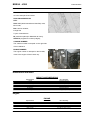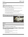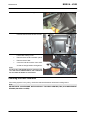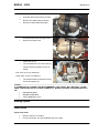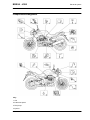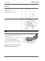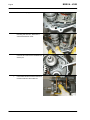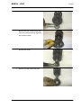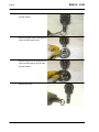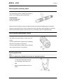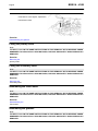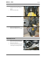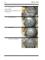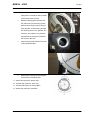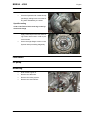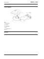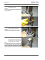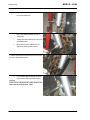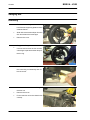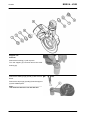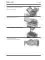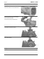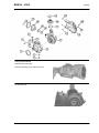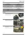
1
SERVICE STATION MANUAL
854316
BREVA - V850
SERVICE STATION
MANUAL
BREVA - V850
While the basic features as described and illustrated in this manual remain unchanged, Moto Guzzi
s.p.a. reserves the right to introduce changes to their own models at any time. All rights regarding
electronic data storage, total or partial reproduction or adaptation of this manual by any means are
reserved for all Countries. Third party products or services referred to in this manual should be considered
only informative and are not binding. Moto Guzzi s.p.a. shall not be liable for any functions or use of these
products.
SERVICE STATION MANUAL
BREVA - V850
This manual provides the main information to carry out regular maintenance operations on your scooter.
This manual is intended to Moto Guzzi Dealers and their qualified mechanics; several concepts have
been deliberately omitted as they are considered unnecessary. As it is not possible to include complete
mechanical notions in this manual, users should have basic mechanical knowledge or minimum
knowledge about the procedures involved when repairing scooters. Without this knowledge, repairing or
checking the vehicle may be inefficient or even dangerous. As the vehicle repair and check procedures
are not described in detail, be extremely cautious so as not to damage components or injure individuals.
In order to optimise customer satisfaction when using our vehicles, Moto Guzzi s.p.a. commits itself to
continually improve its products and the relative documentation. The main technical modifications and
changes in repair procedures are communicated to all Moto Guzzi Sales Outlets and its International
Subsidiaries. These changes will be introduced in the subsequent editions of the manual. In case of
need or further queries on repair and check procedures, consult Moto Guzzi CUSTOMER
DEPARTMENT, which will be prepared to provide any information on the subject and any further
communications on updates and technical changes related to the vehicle.
NOTE Provides key information to make the procedure easier to understand and carry out.
CAUTION Refers to specific procedures to carry out for preventing damages to the vehicle.
WARNING Refers to specific procedures to carry out to prevent injuries to the repairer.
Personal safety Failure to completely observe these instructions will result in serious risk of personal
injury.
Safeguarding the environment Sections marked with this symbol indicate the correct use of the vehicle
to prevent damaging the environment.
Vehicle intactness The incomplete or non-observance of these regulations leads to the risk of serious
damage to the vehicle and sometimes even the invalidity of the guarantee
INDEX OF TOPICS
CHARACTERISTICS
CHAR
SPECIAL TOOLS
S-TOOLS
MAINTENANCE
MAIN
ELECTRICAL SYSTEM
ELE SYS
ENGINE FROM VEHICLE
ENG VE
ENGINE
POWER SUPPLY
ENG
P SUPP
SUSPENSIONS
SUSP
CHASSIS
CHAS
BRAKING SYSTEM
BRAK SYS
BODYWORK
BODYW
PRE-DELIVERY
PRE DE
INDEX OF TOPICS
CHARACTERISTICS
CHAR
BREVA - V850
Characteristics
Rules
Safety rules
Carbon monoxide
If you need to keep the engine running while working on the vehicle, please ensure that you do so in
an open or very well ventilated area. Never run the engine in an enclosed area. If you do work in an
enclosed area, make sure to use a fume extraction system.
CAUTION
EXHAUST EMISSIONS CONTAIN CARBON MONOXIDE, A POISONOUS GAS WHICH CAN CAUSE
LOSS OF CONSCIOUSNESS AND EVEN DEATH.
Fuel
CAUTION
THE FUEL USED TO POWER INTERNAL COMBUSTION ENGINES IS HIGHLY FLAMMABLE AND
MAY BE EXPLOSIVE UNDER CERTAIN CONDITIONS. IT IS THEREFORE RECOMMENDED TO
CARRY OUT REFUELLING AND MAINTENANCE PROCEDURES IN A VENTILATED AREA WITH
THE ENGINE SWITCHED OFF. DO NOT SMOKE DURING REFUELLING AND NEAR FUEL VAPOURS, AVOIDING ANY CONTACT WITH NAKED FLAMES, SPARKS OR OTHER SOURCES
WHICH MAY CAUSE THEM TO IGNITE OR EXPLODE.
DO NOT DISPERSE FUEL IN THE ENVIRONMENT.
KEEP OUT OF THE REACH OF CHILDREN
Hot components
The engine and the exhaust system components become very hot and remain hot for some time after
the engine has been switched off. When handling these components, wear insulating gloves or wait
until the engine and the exhaust system have cooled down.
Used engine oil and transmission oil
CAUTION
IT IS ADVISABLE TO WEAR PROTECTIVE IMPERMEABLE GLOVES WHEN SERVICING THE VEHICLE.
THE ENGINE OR GEARBOX OIL MAY CAUSE SERIOUS INJURIES TO THE SKIN IF HANDLED
FOR PROLONGED PERIODS OF TIME AND ON A REGULAR BASIS.
WASH YOUR HANDS CAREFULLY AFTER HANDLING OIL.
HAND THE OIL OVER TO OR HAVE IT COLLECTED BY THE NEAREST USED OIL RECYCLING
COMPANY OR THE SUPPLIER.
DO NOT DISPOSE OF OIL IN THE ENVIRONMENT
KEEP OUT OF THE REACH OF CHILDREN
CHAR - 7
Characteristics
BREVA - V850
Brake and clutch fluid
BRAKE AND CLUTCH FLUIDS CAN DAMAGE THE PLASTIC OR RUBBER PAINTED SURFACES.
WHEN SERVICING THE BRAKING SYSTEM OR THE CLUTCH SYSTEM, PROTECT THESE COMPONENTS WITH A CLEAN CLOTH. ALWAYS WEAR PROTECTIVE GOGGLES WHEN SERVICING
THESE SYSTEMS. BRAKE AND CLUTCH FLUIDS ARE EXTREMELY HARMFUL FOR YOUR
EYES. IN THE EVENT OF ACCIDENTAL CONTACT WITH THE EYES, RINSE THEM IMMEDIATELY
WITH ABUNDANT COLD, CLEAN WATER AND SEEK MEDICAL ADVICE.
KEEP OUT OF THE REACH OF CHILDREN
Battery electrolyte and hydrogen gas
CAUTION
THE BATTERY ELECTROLYTE IS TOXIC, CORROSIVE AND AS IT CONTAINS SULPHURIC ACID,
IT CAN CAUSE BURNS WHEN IN CONTACT WITH THE SKIN. WHEN HANDLING BATTERY
ELECTROLYTE, WEAR TIGHT-FITTING GLOVES AND PROTECTIVE APPAREL. IN THE EVENT
OF SKIN CONTACT WITH THE ELECTROLYTIC FLUID, RINSE WELL WITH PLENTY OF CLEAN
WATER. IT IS PARTICULARLY IMPORTANT TO PROTECT YOUR EYES BECAUSE EVEN TINY
AMOUNTS OF BATTERY ACID MAY CAUSE BLINDNESS. IF THE FLUID GETS IN CONTACT WITH
YOUR EYES, WASH WITH ABUNDANT WATER FOR FIFTEEN MINUTES AND CONSULT AN EYE
SPECIALIST IMMEDIATELY. THE BATTERY RELEASES EXPLOSIVE GASES; KEEP IT AWAY
FROM FLAMES, SPARKS, CIGARETTES OR ANY OTHER HEAT SOURCES. ENSURE ADEQUATE VENTILATION WHEN SERVICING OR RECHARGING THE BATTERY.
KEEP OUT OF THE REACH OF CHILDREN
BATTERY LIQUID IS CORROSIVE. DO NOT POUR IT OR SPILL IT, PARTICULARLY ON PLASTIC
COMPONENTS. ENSURE THAT THE ELECTROLYTIC ACID IS COMPATIBLE WITH THE BATTERY TO BE ACTIVATED.
Maintenance rules
GENERAL PRECAUTIONS AND INFORMATION
When repairing, dismantling and reassembling the vehicle, follow the recommendations given below
carefully.
BEFORE DISASSEMBLING COMPONENTS
•
Before dismantling components, remove dirt, mud, dust and foreign bodies from the vehicle.
Use the special tools designed for this bike, as required.
COMPONENTS REMOVAL
•
Do not loosen and/or tighten screws and nuts using pliers or any other tools than the specific
wrench.
•
Mark positions on all connection joints (pipes, cables etc.) before separating them, and
identify them with distinctive symbols.
•
Each component needs to be clearly marked to enable identification during reassembly.
•
Clean and wash the dismantled components carefully using a low-flammability detergent.
•
Keep mated parts together since they have "adjusted" to each other due to normal wear.
CHAR - 8
BREVA - V850
•
Some components must be used together or replaced completely.
•
Keep away from heat sources.
Characteristics
REASSEMBLING COMPONENTS
CAUTION
BEARINGS MUST ROTATE FREELY, WITHOUT JAMMING AND/OR NOISE, OTHERWISE, THEY
NEED TO BE REPLACED.
•
Only use ORIGINAL Moto Guzzi SPARE PARTS.
•
Comply with lubricant and consumables use guidelines.
•
Lubricate parts (whenever possible) before reassembling them.
•
When tightening nuts and screws, start from the ones with the largest section or from the
internal ones, moving diagonally. Tighten nuts and screws in successive steps before applying the tightening torque.
•
Always replace self-locking nuts, washers, sealing rings, circlips, O-rings (OR), split pins
and screws with new ones if their tread is damaged.
•
When assembling the bearings, make sure to lubricate them well.
•
Check that each component is assembled correctly.
•
After a repair or routine maintenance procedure, carry out pre-ride checks and test the vehicle on private grounds or in an area with low traffic density.
•
Clean all coupling surfaces, oil guard rims and gaskets before refitting them. Smear a light
layer of lithium-based grease on the oil guard rims. Reassemble oil guards and bearings
with the brand or lot number facing outward (visible side).
ELECTRICAL CONNECTORS
Electric connectors must be disconnected as described below; failure to comply with this procedure
causes irreparable damage to both the connector and the wiring harness:
Press the relative safety clips, if applicable.
•
Grip the two connectors and disconnect them by pulling them in opposite directions.
•
If any signs of dirt, rust, moisture, etc. are noted, clean the inside of the connector carefully
with a jet of compressed air.
•
Ensure that the cables are correctly fastened to the internal connector terminals.
•
Then connect the two connectors, ensuring that they couple correctly (if fitted with clips, you
will hear them "click" into place).
CAUTION
DO NOT DISCONNECT CONNECTORS BY PULLING THE CABLES.
NOTE
THE TWO CONNECTORS CAN ONLY BE CONNECTED IN ONE DIRECTION: CONNECT THEM
THE RIGHT WAY ROUND.
TIGHTENING TORQUES
CAUTION
REMEMBER THAT THE TIGHTENING TORQUES FOR ALL FASTENING ELEMENTS ON WHEELS,
BRAKES, WHEEL AXLES AND ANY OTHER SUSPENSION COMPONENTS PLAY A KEY ROLE
IN ENSURING VEHICLE SAFETY AND MUST COMPLY WITH SPECIFIED VALUES. CHECK THE
CHAR - 9
Characteristics
BREVA - V850
TIGHTENING TORQUES OF FASTENING ELEMENTS ON A REGULAR BASIS AND ALWAYS USE
A TORQUE WRENCH TO REASSEMBLE THESE COMPONENTS. FAILURE TO COMPLY WITH
THESE RECOMMENDATIONS MAY CAUSE ONE OF THESE COMPONENTS TO LOOSEN OR
EVEN DETACH, CAUSING A WHEEL TO LOCK OR COMPROMISING VEHICLE HANDLING. THIS
MAY LEAD TO FALLS, WITH THE RISK OF SERIOUS INJURY OR DEATH.
Running-in
Running the engine in correctly is essential for ensuring engine longevity and functionality. Twisty roads
and gradients are ideal for running in the engine, brakes and suspension effectively. Vary your riding
speed during the running in period. This ensures that components operate in "loaded" conditions and
then "unloaded" conditions, allowing the engine components to cool.
CAUTION
THE CLUTCH MAY EMIT A SLIGHT BURNING SMELL WHEN FIRST USED. THIS PHENOMENON
SHOULD BE CONSIDERED NORMAL AND WILL DISAPPEAR AS SOON AS THE CLUTCH
PLATES GET ADAPTED.
IT IS IMPORTANT TO STRAIN ENGINE COMPONENTS DURING RUN-IN, HOWEVER, MAKE SURE
NOT TO OVERDO THIS.
CAUTION
THE FULL PERFORMANCE OF THE VEHICLE IS ONLY AVAILABLE AFTER THE SERVICE AT
THE END OF THE RUNNING IN PERIOD.
Follow the guidelines detailed below:
•
Do not fully open the throttle grip abruptly at low engine speeds, either during or after the
running in period.
•
During the first 100 Km (62 miles) use the brakes gently, avoiding sudden or prolonged
braking. That is to permit the adequate adjustment of the pad friction material to the brake
discs.
AFTER THE SPECIFIED MILEAGE, TAKE THE VEHICLE TO AN OFFICIAL Moto Guzzi DEALER
FOR THE CHECKS INDICATED IN THE "AFTER RUN-IN" TABLE IN THE SCHEDULED MAINTENANCE SECTION TO AVOID INJURING YOURSELF, OTHERS AND /OR DAMAGING THE VEHICLE.
Vehicle identification
SERIAL NUMBER LOCATION
These numbers are necessary for vehicle registration.
NOTE
ALTERING IDENTIFICATION NUMBERS MAY BE SERIOUSLY PUNISHABLE BY LAW. IN PARTICULAR, MODIFYING THE FRAME NUMBER IMMEDIATELY VOIDS THE WARRANTY.
CHAR - 10
BREVA - V850
Characteristics
This number is composed by numbers and letters,
as in the example shown below.
ZGULPB000YMXXXXXX
KEY:
ZGU: WMI (World manufacture identifier) code;
LP: model;
B00: version variation;
0: digit free
Y year of manufacture
M: production plant (M= Mandello del Lario);
XXXXXX: progressive number (6 digits);
CHASSIS NUMBER
The chassis number is stamped on the right side
of the headstock.
ENGINE NUMBER
The engine number is stamped on the left side,
close to the engine oil level check cap.
Dimensions and mass
WEIGHT AND DIMENSIONS
Specification
Length
Width
Maximum height
Saddle height
Minimum earth clearance
Wheelbase
Kerb weight
Desc./Quantity
2195 mm (86.4 in)
870 mm (34.2 in)
1125 mm (44.3 in)
800 mm (31.5 in)
185 mm (7.3 in)
1495 mm (58.8 in)
248 kg (547 pounds)
Engine
ENGINE
Specification
Type
No. of cylinders
Cylinder arrangement
Total engine capacity
Bore / stroke
Desc./Quantity
traverse-mounted twin-cylinder four-stroke V 90°
2
V 90°
877 cm³ (53.5 cu.in)
92 x 66 mm (3.6 x 2.6 in)
CHAR - 11
BREVA - V850
Characteristics
Specification
Compression ratio
Electric
Engine idle speed
Clutch
Lubrication
Air filter
Cooling
Fuel system
Diffuser
Fuel
Desc./Quantity
9.8 :1
starter
1100 ± 100 rpm
dry, twin disc with hydraulic control
Pressure-fed, controlled by valves and trochoidal pump
cartridge-type dry filter
air
Electronic injection (Weber . Marelli) with stepper motor
Ø 45 mm (1.77 in)
Premium unleaded petrol, minimum octane rating 95 (NORM)
and 85 (NOMM)
Timing system diagram:
2 rod valves and rocking levers
Valid values with checking clearance between rocking levers
inlet: 0.10 mm (0.0039 in)
and valve
outlet: 0.15 mm (0.0059 in)
Transmission
TRANSMISSION
Specification
Main transmission
Gearbox
Desc./Quantity
with gears, ratio: 23/36 = 1 :0.6389
Mechanical, 6 speeds with foot lever on the left hand side of
the engine
1st gear : 17/38 = 1 :2.2353
2nd gear : 20/34 = 1:1.7
3rd gear : 23/31 = 1:1.3478
4th gear : 26/29 = 1:1.1154
5th gear : 31/30 = 1:0.9677
6th gear : 29/25 = 1:0.8621
with U-joint
12/44 = 1:3.6667
Gear ratios:
Final drive
Ratio
Capacities
CAPACITY
Specification
Engine oil
Gearbox oil
Transmission oil
Fuel (reserve included)
Fuel reserve
Fork oil
Seats
Vehicle maximum load
Desc./Quantity
Oil and oil filter change 3600 cm³ (219 cu.in)
500 cm³ (30.5 cu.in)
380 cm³ (23.2 cu.in)
23 l (6.1 gal)
4 l (1.06 gal)
400 ± 2.5 cm³ (24.4 ± 0.15 in) (for each stem)
2
230 Kg (507 pounds) (rider + passenger + luggage)
Electrical system
ELECTRICAL SYSTEM
Specification
Outer spark plug
Electrode gap
Battery
Alternator (permanent magnet type)
Main fuses
AUXILIARY FUSES
Daylight running light
Low-beam light
High-beam light
Turn indicators
CHAR - 12
Desc./Quantity
NGK BPR6ES
0.6 - 0.7 mm (0.024 - 0.028 in)
12 V - 18 Ampere/hour
12 V - 550 W
30 A
3A - 15A - 20A
12V - 5 W
12 V - 55 W H7
12 V - 65 W H9
12V - 10 W (orange bulb)
BREVA - V850
Characteristics
Specification
Rear daylight running light/stop light
Dashboard lighting
License plate light
Turn indicator warning light
ABS warning light
Neutral gear warning light
Alarm warning light
Side stand down warning light
Low fuel warning light
High beam warning light
Antitheft device warning light
Gear shift warning light
Desc./Quantity
LED
LED
12V - 5 W
LED
LED
LED
LED
LED
LED
LED
LED
LED
Frame and suspensions
CHASSIS
Specification
Type
Trail
Headstock angle
Front
Wheel travel
Rear
Wheel travel
Desc./Quantity
high strength steel tube chassis
120 mm (4.72 in)
25° 30'
hydraulic telescopic fork; Ø 45 mm (1.77 in)
120 mm (4.72 in)
single arm suspension with progressive linkage, single shock
absorber with adjustable rebound and ergonomic knob for
spring preloading adjustment.
140 mm (5.5 in)
SIZES A AND B
Specification
Size A
Size B
Desc./Quantity
758.9 +/- 1 mm (29.88 +/- 0.04 in)
345.5 mm (13.60 in)
Brakes
BRAKES
Specification
Front
Rear
Desc./Quantity
twin Ø 320 mm (12.6 in) stainless steel floating disc, calliper
with 4 different and counteracting plungers
282 mm (11.1 in) diam. stainless steel disc
CHAR - 13
BREVA - V850
Characteristics
Wheels and tyres
WHEELS AND TYRES
Specification
Type
Front wheel rim
Rear wheel rim
Tyres
Desc./Quantity
hollow 3-spoke rim in chilled cast aluminium alloy
3.50" x 17"
5.50" x 17"
METZELER Roadtec Z6
MICHELIN Pilot Road
DUNLOP D220 ST Sportmax
120/70 - ZR 17" 58 W
2.5 bar (250 kPa) (36.3 PSI)
2.5 bar (250 kPa) (36.3 PSI)
180/55 - ZR 17" 73 W
2.8 bar (280 kPa) (40.6 PSI)
2.8 bar (280 kPa) (40.6 PSI)
Front
Inflation pressure (front)
Inflation pressure with passenger (front)
Rear
Inflation pressure (rear)
Inflation pressure with passenger (rear)
Tightening Torques
HEADS
Name
Oil cap (2)
Exhaust system stud bolt (4)
Rocking lever support nut - M10x1.5 (8)
Rocking lever nut (4)
Set screw - TE M6x16 (4)
Head cover screw - M6x25 (16)
Head fixing screw (4)
Oil temperature sensor
Oil temperature sensor container
Outer Spark plugs
Spark plug hole cap
Torque in Nm
25 Nm (18.44 lbf ft)
10 Nm (7.38 lbf ft) - Loctite 648
15 Nm (11.06 lbf ft) + 90º + 90º
10 Nm (7.38 lbf ft)
10 Nm (7.38 lbf ft)
10 Nm (7.38 lbf ft)
15 Nm (11.06 lbf ft) + 90º
11 Nm (8.11 lbf ft) - Loctite 243
11 Nm (8.11 lbf ft) - Loctite 601
30 Nm (22.13 lbf ft) - Molikote
11 Nm (8.11 lbf ft)
CRANKCASE
Name
Crankcase stud bolt - cylinder (8)
Transmission side flange stud bolt - M8x66 (3)
Transmission side flange stud bolt - M8x75 (2)
Crankshaft flange screw - TE M8x25 (14)
Timing system cover screw - TCEI M8x55 (4)
Timing system cover screw - TCEI M6x30 (10)
Oil vapour union screw - TCEI M6x20 (2)
Timing system outer cover screw - TCEI M6x16 (4)
Screw TSPEI M4x8 (2)
TCEI M6x40 Screw (2)
Timing sensor - TCEI M5x12 (2)
Crankcase stud bolts - chassis (4)
Torque in Nm
25 Nm (18.44 lbf ft)
35 Nm (25.81 lbf ft)
35 Nm (25.81 lbf ft)
25 Nm (18.44 lbf ft)
25 Nm (18.44 lbf ft)
10 Nm (7.38 lbf ft)
10 Nm (7.38 lbf ft)
10 Nm (7.38 lbf ft)
5 Nm (3.69 lbf ft) - Loctite 243
10 Nm (7.38 lbf ft)
6 Nm (4.42 lbf ft)
40 Nm (29.5 lbf ft) - Loctite 601
OIL SUMP
Name
Cap on oil sump flange (2)
Oil pipe on sump
Oil sump lower screw - TCEI M6x30 (4)
Oil sump screw - TCEI M6x55 (14)
Oil sump screw - TCEI M6x60 (2)
Oil drainage plug - M10x1 (1)
Oil filter (1)
Oil filter fitting (1)
Oil pipe in sump
Pressure-relief plug
Oil intake filter fixing screw - TCEI M6x16 (1)
CHAR - 14
Torque in Nm
20 Nm (14.75 lbf ft)
20 Nm (14.75 lbf ft)
10 Nm (7.38 lbf ft)
10 Nm (7.38 lbf ft)
10 Nm (7.38 lbf ft)
20 Nm (14.75 lbf ft)
15 Nm (11.06 lbf ft)
40 Nm (29.5 lbf ft) - Loctite 243
20 Nm (14.75 lbf ft) - Loctite 648
40 Nm (29.5 lbf ft)
10 Nm (7.38 lbf ft) - Loctite 648
BREVA - V850
Characteristics
OIL PUMP
Name
Oil pump fixing screw - TBEI M6x30 (3)
Oil pump gear nut - M10x1.25 (1)
Oil delivery pipe screw (1)
Oil pressure sensor
Torque in Nm
10 Nm (7.38 lbf ft) - Loctite 243
20 Nm (14.75 lbf ft)
17 Nm (12.54 lbf ft)
45 Nm (33.19 lbf ft)
TIMING SYSTEM
Name
Camshaft flange screw - TE M6x20 (3)
Timing system gear nut on camshaft - M18 (1)
Timing system gear nut on crankshaft - M25 (1)
Camshaft support screw on timing system cover - TCEI M4x10
(4)
Belt tension
Torque in Nm
10 Nm (7.38 lbf ft)
150 Nm (110.63 lbf ft)
120 Nm (88.51 lbf ft)
5 Nm (3.69 lbf ft) - Loctite 243
50 Nm (36.88 lb ft)
GENERATOR
Name
Alternator fixing screw - TCEI M8x45 (1)
Alternator fixing nut - M10x1.5 (1)
Alternator pulley nut on crankshaft - M16 (1)
Torque in Nm
22 Nm (16.23 lbf ft)
30 Nm (22.13 lbf ft)
80 Nm (59 lbf ft) - Loctite 243
CRANKSHAFT - FLYWHEEL
Name
Start-up crown fixing screw on flywheel (8)
Connecting rod screw (4) - pre-tightening
Connecting rod screw (4) - final tightening
Flywheel fixing screw on crankshaft - M8x25 (6)
Torque in Nm
18 Nm (13.28 lbf ft) - Loctite 243
40 Nm (29.5 lbf ft)
80 Nm (59 lbf ft)
42 Nm (30.98 lbf ft) - Loctite 243
GEAR
Name
Gear shift cable lever nut
Gear shift tie rod lever nut on gear pre-selector
Gearbox to crankcase fixing nut - M8 (5)
TE flanged screw fixing gearbox to crankcase - M8x45 (1)
Oil cap M18x1.5 (1)
Breather cap (1)
Gear in neutral sensor (1)
Oil drainage plug - M10x1 (1)
Transmission shaft ring nut (1)
Torque in Nm
10 Nm (7.38 lbf ft)
10 Nm (7.38 lbf ft)
20 Nm (14.75 lbf ft)
20 Nm (14.75 lbf ft)
28 Nm (20.65 lbf ft)
8 Nm (5.9 lbf ft)
10 Nm (7.38 lbf ft)
24 Nm (17.7 lbf ft)
100 Nm (73.76 lbf ft)
CHASSIS TO ENGINE UNIT
Name
M6x40 TCEI DA screw
Reduction
Torque in Nm
8 -12 Nm
20 Nm
FUEL SUPPLY CONTROL UNIT
Name
M5x12 TCEI screw
Stainless M5x16 TBEI flanged screw
M6x25 TCEI DA screw
Torque in Nm
6 -7 Nm
6 -7 Nm
8 -12 Nm
CHASSIS
Name
Electronic control unit retainer + coil plates
Electronic control unit retainer
Tank support rubber rings to chassis retainer
Gearbox to chassis retainer
Coil retainer
Engine retainer
Torque in Nm
10 Nm
10 Nm
25 Nm
80 Nm
2 Nm
80 Nm
CHAR - 15
BREVA - V850
Characteristics
Name
Left and right footrest plate to chassis upper retainer
Right footrest plate to chassis lower retainer
Left footrest plate to chassis lower retainer
Right/left protection cover retainer
Plate ring to plate retainer
Handgrip to chassis fixing screw
Cover to handgrip retainer
Torque in Nm
20 Nm
30 Nm
30 Nm
6 Nm
6 Nm
25 Nm
25 Nm
FOOTRESTS AND LEVERS
Name
Footrest rubber retainer
Rod retainer (nut)
Gear shift lever / brake pin retainer
Gear shift lever / pre-selector retainer
Spring hook pin
Torque in Nm
10 Nm
10 Nm
10 Nm
10 Nm
4 Nm
SIDE STAND
Name
Stand plate to engine retainer
Side stand retainer pin
Switch fixing screw
Lock nut
Torque in Nm
80 Nm
10 Nm
10 Nm
30 Nm
CENTRE STAND
Name
Stand to plates fixing screw
Pipe guide ring to plates fixing screw
Torque in Nm
50 Nm
10 Nm
FRONT SUSPENSION
Name
Speed sensor retainer
Tube lock plate to steering base retainer
Fork stem to lower / upper plate retainer
Headstock ring nut
Headstock counter ring nut
Upper yoke fixing cap
Fork hubs closing
Torque in Nm
10 Nm
6 Nm
25 Nm
40 Nm
manual + 90 degrees
100 Nm
10 Nm
REAR SUSPENSION
Name
Shock absorber to chassis retainer - 8.8
Double connecting rod/shock absorber retainer - 10.9
Single connecting rod/double connecting rod retainer - 10.9
Single connecting rod to chassis retainer - 8.8
Double connecting rod/swingarm retainer - 10.9
Torque in Nm
50 Nm
40 Nm
50 Nm
50 Nm
50 Nm
AIR FILTER CASING
Name
Filter casing cover/filter casing bracket
Blow-by tank to filter casing cover retainer
Air temperature sensor retainer
Torque in Nm
3 Nm
3 Nm
2 Nm
EXHAUST
Name
Exhaust pipe to engine retainer
Exhaust pipe to compensator retainer (clamp)
Compensator to plate retainer
Compensator to silencer retainer (clamp)
Lambda probe retainer
Silencer to support retainer (screw +nut)
CHAR - 16
Torque in Nm
25 Nm
10 Nm
25 Nm
10 Nm
38 Nm
25 Nm
BREVA - V850
Characteristics
FRONT WHEEL
Name
Wheel pin nut
Disc retainer
Torque in Nm
80 Nm
30 Nm
REAR WHEEL
Name
Disc retainer
Rear wheel retainer 10.9
Torque in Nm
30 Nm
110 Nm
FRONT BRAKING SYSTEM
Name
Front brake right and left calliper retainer
Torque in Nm
40 Nm
REAR BRAKING SYSTEM
Name
Rear brake calliper retainer
Rear brake lever pin
Rear brake fluid reservoir retainer
Rear brake fluid reservoir support to plate retainer
Rear brake rod lock nut
Brake lever spring to plate retainer
Brake pump retainer
Torque in Nm
50 Nm
15 Nm
3 Nm
10 Nm
manual
6 Nm
10 Nm
HANDLEBAR AND CONTROLS
Name
Half-handlebar to steering plate retainer
Handlebar pipes to half-handlebar retainer
Anti-vibration counterweight fastener
Torque in Nm
25 Nm
25 Nm
10 Nm
ELECTRICAL SYSTEM
Name
Horn retainer
Speed sensor to front fork retainer
Torque in Nm
15 Nm
12 Nm
INSTRUMENT PANEL AND LIGHTS
Name
Instrument panel support to light support retainer
Instrument panel support to fork upper plate retainer
Instrument panel retainer
Light support to fork lower plate retainer
Light + turn indicators retainer
Rear light to handgrip retainer
Torque in Nm
10 Nm
25 Nm
3 Nm
25 Nm
10 Nm
4 Nm
FUEL PUMP FLANGE
Name
Tank breather joint
Pump support to tank retainer
Torque in Nm
6 Nm
4 Nm
FUEL TANK
Name
Filler to tank retainer
Rear screw fixing the tank to the chassis - M8x45
Torque in Nm
4 Nm
25 Nm
CHASSIS / FAIRINGS (FRONT)
Name
Air inlet to tank retainer
Lug to engine retainer
Right to left lug retainer
Torque in Nm
4 Nm
25 Nm
4 Nm
CHAR - 17
BREVA - V850
Characteristics
Name
Front mudguard retainer
Torque in Nm
4 Nm
CHASSIS/ FAIRINGS (REAR)
Name
Tail section + fairing retainer
Tail section to handgrip retainer
Net hooks to chassis retainer
Retroreflector to support retainer
Retroreflector support to license plate holder retainer
License plate lamp to license plate holder retainer
Torque in Nm
4 Nm
4 Nm
25 Nm
4 Nm
4 Nm
4 Nm
FINISHINGS
Name
Ignition lock retainer - shear head screw
Ignition lock retainer
Torque in Nm
- Nm
25 Nm
SWINGARM
Name
Swingarm on bushing clamp retainer
Swingarm on bevel gear pair retainer
Reaction rod to bevel gear pair retainer
Reaction rod to chassis retainer
Swingarm bolt to swingarm retainer
Preloading bushing to swingarm bolt retainer
Torque in Nm
10 Nm
50 Nm
50 Nm
50 Nm
60 Nm
10 Nm
Overhaul data
Assembly clearances
Cylinder - piston assy.
Measurement of the cylinder diameter must be done at three heights, turning the dial gauge 90°.
Check the clearance between the cylinders and pistons; if it exceeds the value specified, it is necessary
to replace cylinders and pistons.
The pistons of an engine must be balanced; a weight difference of up to 1.5 (0.0033 lb) is admitted.
ADMITTED MEASUREMENTS
Specification
cylinder diameter
piston diameter
fitting clearance
CHAR - 18
Desc./Quantity
92.000 - 92.020 mm (3.62204 - 3.62282 in)
91.942 - 91.972 mm (3.6197 - 3.6209 in)
0.048 - 0.068 mm (0.00189 - 0.00268 in)
BREVA - V850
Characteristics
Piston rings
Check the sealing piston rings and the oil scraper.
On each piston there are:
1 top piston ring;
1 middle stepped piston ring;
1 oil scraper piston ring.
The ends of the fitted piston rings are out of phase.
Fitting backlash detected between the ring thickness and seats on the piston:
Sealing rings and oil scraper 0.030 - 0.065 mm (0.00118 - 0.00256 in)
Gap between the end of the piston rings inserted in the cylinder:
Upper sealing ring and stepped ring 0.40 - 0.65 mm (0.00158 - 0.00255 in)
Oil scraper ring 0.30 - 0.60 mm (0.00118 - 0.00236 in).
Turn the rings so that the coupling ends are 120 degrees from each other.
Crankcase - crankshaft - connecting rod
CAMSHAFT (CAM) SUPPORT DIAMETER AND THEIR SEATS ON THE CRANKCASE
(TIMING SYSTEM SIDE)
Specification
Shaft support diameter
Seat diameter on base
fitting clearance
Desc./Quantity
47.000 - 46.984 mm
(1.85039 ÷ 1.84976 inch)
47.025 - 47.050 mm
(1.85137 ÷ 1.85236 inch )
0.025 - 0.066 mm
(0.00098 ÷ 0.00260 inch)
CAMSHAFT (CAM) SUPPORT DIAMETER AND THEIR SEATS ON THE CRANKCASE
(FLYWHEEL SIDE)
Specification
Shaft support diameter
Seat diameter on base
fitting clearance
Desc./Quantity
32.000 - 31.984 mm
(1.25984 ÷ 1.25921 inch)
32.025 - 32.050 mm
(1.26082 ÷ 1.26181 inch)
0.025 - 0.066 mm
(0.00098 ÷ 0.00260 inch)
CHAR - 19
BREVA - V850
Characteristics
TAPPET-SEAT COUPLING ON CRANKCASE DATA (PRODUCTION)
Specification
Seats diameter
Desc./Quantity
22.021 - 22.000 mm
(0.86697 ÷ 0.86614 inch)
21.996 - 21.978 mm
(0.86598 ÷ 0.86527 inch)
0.004 - 0.043 mm
(0.00016 ÷ 0.00169 in.)
Tappet external diameter
Fitting clearances
Recommended products chart
RECOMMENDED PRODUCTS
Product
AGIP RACING 4T 10W-60
Description
Engine oil
AGIP GEAR SAE 80 W 90
AGIP GEAR MG/S SAE 85 W 90
AGIP FORK 7.5W
AGIP GREASE SM2
Neutral grease or petroleum jelly.
AGIP BRAKE 4 / BRAKE 5.1
Transmission oil
Gearbox oil
Fork oil
Lithium grease with molybdenum for
bearings and other points needing lubrication
Battery poles
Brake fluid
AGIP BRAKE 4 / BRAKE 5.1
Clutch fluid
Specifications
SAE 10W - 60. As an alternative to recommended fluids, use top branded oils
with performances that meet or exceed
the requirements of CCMC G-4 API. SG
specifications.
SAE 5W / SAE 20W
NLGI 2
As an alternative for recommended fluids, use top branded fluids that meet or
exceed the requirements of SAE J1703,
NHTSA 116 DOT 4, ISO 4925 synthetic
fluid specifications.
As an alternative for recommended fluids, use top branded fluids that meet or
exceed the requirements of SAE J1703,
NHTSA 116 DOT 4, ISO 4925 synthetic
fluid specifications.
NOTE
USE ONLY NEW BRAKE FLUID. DO NOT MIX DIFFERENT BRANDS OR TYPES OF OIL WITHOUT
CHECKING THEIR BASE COMPATIBILITY.
CHAR - 20
INDEX OF TOPICS
SPECIAL TOOLS
S-TOOLS
BREVA - V850
Special tools
SPECIAL TOOLS
Stores code
05.94.86.30
Description
Belt tension tool
05.91.17.30
Front cover insertion cone
05.91.25.30
Gearbox opening
05.92.80.30
Piston ring clamp
05.92.72.30
Timing system cover sealing ring punch
01.92.91.00
Wrench for removing the cover on sump
and filter
S-TOOLS - 22
BREVA - V850
Special tools
Stores code
05.90.25.30
Description
Gearbox support
19.92.96.00
Graduated dial to control ignition timing
17.94.75.60
Arrow to control ignition timing
12.91.18.01
Tool to lock the flywheel and the starting
ring gear
12.91.36.00
Tool to remove the flywheel-side flange
10.90.72.00
Tool for valve removal and refitting
30.90.65.10
Tool for clutch fitting
S-TOOLS - 23
BREVA - V850
Special tools
Stores code
14.92.71.00
Description
Tool to fit the sealing ring on the flywheelside flange
12.91.20.00
Tool to fit the flywheel-side flange together with seal ring on the crankshaft
19.92.71.00
Tool to fit the seal ring on the flywheelside flange
14.92.73.00
Tool for camshaft gear sealing
981006
Graduated dial hub
AP8140190
Tool for steering tightening
000019663300
Tool for clutch shaft removal
S-TOOLS - 24
BREVA - V850
Special tools
Stores code
30.91.28.10
Description
Clutch body locking
05.90.27.30
Gearbox support
05.90.27.31
Gearbox oil seal buffer
05.90.27.32
Buffer handgrip
05.90.27.33
Ball joint sealing buffer
05.90.27.34
Wrench for pinion ring nut
05.90.27.35
Pinion oil seal buffer
S-TOOLS - 25
BREVA - V850
Special tools
Stores code
05.90.27.36
Description
Bevel gear pair support
GU14912603
Hook spanner for fixing ring nut of the
clutch shaft internal body
S-TOOLS - 26
INDEX OF TOPICS
MAINTENANCE
MAIN
BREVA - V850
Maintenance
Maintenance chart
NOTE
CARRY OUT MAINTENANCE OPERATIONS AT HALF THE INTERVALS SPECIFIED IF THE VEHICLE IS USED IN PARTICULAR RAINY OR DUSTY CONDITIONS, OFF ROAD OR FOR TRACK
USE.
AT EVERY START-UP
Action
Engine oil pressure warning light - check and clean, adjust, grease or replace if necessary
BEFORE EACH RIDE AND EVERY 2000 KM (1250 MI)
Action
Tyre pressure - Adjust
Brake pad wear - Check and clean, adjust or replace if necessary
AFTER RUN-IN (1,500 KM (932 MI)
Action
Exhaust pipe flange bolts - Check and clean, adjust, grease or replace if necessary
Transmission cables and controls - Check and clean, adjust, grease or replace if necessary
Steering bearings and steering clearance - Check and clean, adjust, grease or replace if necessary.
Disc brakes - Check and clean, adjust or replace if necessary
Engine oil filter - Replace
Fork - Check and clean, adjust and lubricate
General vehicle operation - Check and clean, adjust, grease or replace if necessary.
Braking systems - Check and clean, adjust, grease or replace if necessary
Light circuit - Check and clean, adjust or replace if necessary
Safety switches - Check and clean, adjust, grease or replace if necessary
Gearbox oil - Change
Engine oil - Change
Final transmission oil - Change
Tyres - Check and clean, adjust, grease or replace if necessary
Tyre pressure - Adjust
Engine revs at idle speed - Adjustment.
Valve clearance adjustment - Adjust
Wheels - Check and clean, adjust, grease or replace if necessary
Bolts, nuts and screws tightening - Check and clean, adjust, grease or replace if necessary
Battery terminals tightening - Check and clean, adjust, grease or replace if necessary
Cylinder synchronisation - Check and clean, adjust, grease or replace if necessary
Suspensions and setting - Check and clean, adjust, grease or replace if necessary
Brake pad wear - Check and clean, adjust or replace if necessary
EVERY 4 YEARS
Action
Fuel pipes - Replace
Brake pipes - Replacement
EVERY 5000 KM (3125 MI) - IF THE VEHICLE IS USED FOR RACING
Action
Outer spark plugs - Replace
Engine oil filter - Replace
Engine oil - Change
Purge fluid present in oil drainage pipe from the filter housing - Clean
Clutch wear - Check and clean, adjust, grease or replace if necessary
EVERY 10,000 KM (6250 MILES) OR 12 MONTHS
Action
Outer spark plugs - Replace
Idle mixture (CO) - Check and clean, adjust, grease or replace if necessary
Transmission cables and controls - Check and clean, adjust, grease or replace if necessary
MAIN - 28
BREVA - V850
Maintenance
Action
Steering bearings and steering clearance - Check and clean, adjust, grease or replace if necessary.
Wheel bearings - Check and clean, adjust, grease or replace if necessary
Disc brakes - Check and clean, adjust or replace if necessary
Air filter - Check and clean, adjust, grease or replace if necessary
Engine oil filter - Replace
General vehicle operation - Check and clean, adjust, grease or replace if necessary.
Braking systems - Check and clean, adjust, grease or replace if necessary
Gearbox oil - Change
Engine oil - Change
Final transmission oil - Change
Valve clearance adjustment - Adjust
Wheels - Check and clean, adjust, grease or replace if necessary
Bolts, nuts and screws tightening - Check and clean, adjust, grease or replace if necessary
Cylinder synchronisation - Check and clean, adjust, grease or replace if necessary
Purge fluid present in oil drainage pipe from the filter housing - Clean
Fuel pipes - Check and clean, adjust, grease or replace if necessary
Brake pipes - Check and clean, adjust, grease or replace if necessary
Clutch wear - Check and clean, adjust, grease or replace if necessary
AFTER THE FIRST 10,000 KM (6,250 MILES) AND THEN AFTER EVERY 20,000 KM (12,500
MILES)
Action
Fork oil - Change
Fork oil seals - Replace
EVERY 20,000 KM (12,500 MI) OR 24 MONTHS
Action
Alternator belt - Adjust; EVERY 50,000 km (31,050 mi)
Air filter - Replace
Fork - Check and clean, adjust and lubricate
Brake fluid - change
Suspensions and setting - Check and clean, adjust, grease or replace if necessary
Brake pad wear - Check and clean, adjust or replace if necessary
Transmission fluid
Check
• Keep the vehicle upright with both wheels on the
ground.
• Unscrew and remove the cap/dipstick (1).
• The level is correct if the oil is close to the hole
of the cap/dipstick (1).
• If the oil is lower than specified, top-up until it
reaches the cap/dipstick hole (1).
CAUTION
DO NOT ADD ADDITIVES OR ANY OTHER SUBSTANCE TO
THE FLUID. WHEN USING A FUNNEL OR ANY OTHER ELEMENT, MAKE SURE IT IS PERFECTLY CLEAN.
MAIN - 29
Maintenance
BREVA - V850
Replacement
CAUTION
THE UNIT MUST BE HOT WHEN THE OIL IS CHANGED AS UNDER SUCH CONDITIONS OIL IS
FLUID AND THEREFORE EASY TO DRAIN.
NOTE
RIDE SOME km (miles) TO WARM UP ENGINE OIL
•
Place a container with + 400 cm³ (25 cu in) capacity under the drainage plug (3).
•
Unscrew and remove the drainage plug (3).
•
Unscrew and remove the breather cap (2).
•
Drain the oil into the container; allow several minutes for oil to drain out completely.
•
Check and if necessary, replace the sealing washer of drainage plug (3).
•
Remove any metal scrap attached to the drainage plug (3) magnet.
•
Screw and tighten the drainage plug (3).
•
Pour new oil through the fill opening (1) until it reaches the cap/dipstick hole (1).
CAUTION
DO NOT ADD ADDITIVES OR ANY OTHER SUBSTANCE TO THE FLUID. WHEN USING A FUNNEL
OR ANY OTHER ELEMENT, MAKE SURE IT IS PERFECTLY CLEAN.
•
Screw and tighten the caps (1 - 2).
Engine oil
Check
CAUTION
ENGINE MUST BE WARM TO CHECK ENGINE OIL LEVEL.
NOTE
DO NOT LET THE ENGINE IDLE WITH THE VEHICLE AT STANDSTILL TO WARM UP THE ENGINE
OIL AND REACH THE OPERATING TEMPERATURE OF ENGINE OIL. OIL IS BEST CHECKED
AFTER RUNNING FOR ABOUT 15 KM (10 miles).
•
Shut off the engine.
•
Keep the vehicle upright with the two wheels on the ground.
•
Unscrew and remove the dipstick (1).
•
Clean the dipstick (1).
•
Reinsert the dipstick (1) into the opening but do not screw it.
MAIN - 30
BREVA - V850
•
Remove the dipstick (1).
•
Check oil level on the dipstick (1).
•
The oil level is correct when it close to the "MAX" mark.
Maintenance
MAX = maximum level
MIN = minimum level
Add engine oil if required:
•
Unscrew and remove the dipstick (1).
•
Top-up with engine oil until it goes above the minimum level marked "MIN".
CAUTION
DO NOT ADD ADDITIVES OR ANY OTHER SUBSTANCE TO
THE FLUID. WHEN USING A FUNNEL OR ANY OTHER ELEMENT, MAKE SURE IT IS PERFECTLY CLEAN.
Replacement
NOTE
HOT OIL IS MORE FLUID AND WILL DRAIN OUT MORE EASILY AND COMPLETELY.
•
Place a container with + 4000 cm³ (245
cu in) capacity under the drainage plug
(2).
•
Unscrew and remove the drainage
plug (2).
•
Unscrew and remove the filler plug (3).
•
Drain the oil into the container; allow
several minutes for oil to drain out completely.
•
Check and if necessary, replace the
sealing washers of drainage plug (2).
•
Remove any metal scrap attached to
the drainage plug (2) magnet.
MAIN - 31
Maintenance
•
BREVA - V850
Screw and tighten the drainage plug
(2).
•
Pour new oil until it goes above the
minimum level marked "MIN".
Engine oil filter
•
Unscrew and remove the engine oil filter from its seat.
NOTE
NEVER REUSE AN OLD FILTER.
•
Spread a thin layer of oil on the sealing ring of the new engine oil filter.
•
Fit and screw the new oil filter in its seat.
Gearbox Oil
Inspection
CHECKING AND TOPPING UP
CAUTION
ENGINE MUST BE WARM TO CHECK GEARBOX OIL LEVEL.
NOTE
DO NOT LET THE ENGINE IDLE WITH THE VEHICLE AT STANDSTILL TO WARM UP THE ENGINE
OIL AND REACH THE OPERATING TEMPERATURE OF ENGINE OIL. OIL IS BEST CHECKED
AFTER RUNNING FOR ABOUT 15 KM (10 miles).
•
Shut off the engine.
•
Keep the vehicle upright with both
wheels on the ground.
•
Undo and remove the dipstick opening
(1) located on the right side of the gearbox.
•
The level is correct if the oil is close to
the hole of the dipstick (1).
If necessary:
MAIN - 32
BREVA - V850
•
Maintenance
Top-up with oil until it reaches the dipstick opening (1).
CAUTION
DO NOT ADD ADDITIVES OR ANY OTHER SUBSTANCE TO
THE FLUID. WHEN USING A FUNNEL OR ANY OTHER ELEMENT, MAKE SURE IT IS PERFECTLY CLEAN.
Replacement
NOTE
HOT OIL IS MORE FLUID AND WILL DRAIN OUT MORE EASILY AND COMPLETELY.
• Place a container with suitable capacity under the
drainage plug (2).
• Unscrew and remove the drainage plug (2).
• Unscrew and remove the filler cap (1).
• Drain the oil into the container; allow several minutes for oil to drain out completely.
• Check and replace, if necessary, the sealing
washers of drainage plug (2).
• Remove any metal scrap attached to the drainage plug (2) magnet.
• Screw and tighten the drainage plug (2).
• Pour in new oil until it reaches the dipstick opening (1).
• Tighten the filler cap (1).
CAUTION
DO NOT ADD ADDITIVES OR ANY OTHER SUBSTANCE TO
THE FLUID. WHEN USING A FUNNEL OR ANY OTHER ELEMENT, MAKE SURE IT IS PERFECTLY CLEAN.
Air filter
•
Remove the fuel tank.
•
Disconnect the connector from the air
temperature sensor.
MAIN - 33
Maintenance
•
Remove the oil breather pipe.
•
Unscrew and remove the five screws.
•
Lift the filter casing cover.
•
Remove the acoustic insulation panel.
•
Remove the air filter.
•
Cover the inlet duct with a clean cloth
BREVA - V850
so that no foreign bodies could get into.
NOTE
DO NOT START THE ENGINE WITHOUT THE AIR FILTER.
TO CLEAN THE FILTERING ELEMENT, USE A PRESSURE
AIR JET FROM THE INSIDE TO THE OUTSIDE.
Checking the valve clearance
If the timing system is very noisy, check the clearance between valves and rocking levers.
NOTE
ADJUST WITH COLD ENGINE, WITH PISTON AT TOP DEAD CENTRE (TDC) IN COMPRESSION
STROKE (VALVES CLOSED).
MAIN - 34
BREVA - V850
•
Remove the fuel tank.
•
Unscrew and remove the two screws.
•
Remove the spark plugs protection.
•
Disconnect both spark plug tubes.
•
Unscrew and remove the eight screws.
•
Remove the head cover.
•
loosen the nut (1);
•
use a screwdriver on the set screw (2)
Maintenance
until the following clearances are obtained:
- inlet valve: 0.10 mm (0.0039 in)
- outlet valve: 0.15 mm (0.0059 in).
•
The measurement must be done using
a thickness gauge (3).
CAUTION
IF CLEARANCE IS LARGER THAN RECOMMENDED, THE TAPPET WILL BE NOISY. OTHERWISE, THE VALVES DO NOT CLOSE CORRECTLY, WHICH CAN LEAD TO PROBLEMS SUCH
AS:
•
PRESSURE DROP;
•
ENGINE OVERHEAT;
•
VALVE BURNOUT, ETC.
Braking system
Level check
Brake fluid check
•
Rest the vehicle on its stand.
•
For the front brake, turn the handlebar fully to the right.
MAIN - 35
Maintenance
•
BREVA - V850
For the rear brake, keep the vehicle upright so that the fluid in the reservoir is at the same
level with the plug.
•
Make sure that the fluid level in the reservoir is above the "MIN" reference mark:
MIN = minimum level
MAX = maximum level
If the fluid does not reach at least the "MIN" reference mark:
•
Check brake pads and disc for wear.
•
If the pads and/or the disc do not need replacing, top-up the fluid.
Top-up
Front brake:
•
Unscrew the two screws (1) of the
brake fluid reservoir (2) using a Phillips
screwdriver.
•
Lift and remove the cover (3) and
screws (1) as well.
•
Remove the gasket (4).
Rear brake:
•
Unscrew and remove the cap (5).
•
Remove the gasket (6).
•
Top-up the reservoir with brake fluid to
the correct level, which is between the
two "MIN" and "MAX" reference marks.
RISK OF BRAKE FLUID SPILLS. DO NOT OPERATE THE
BRAKE LEVER WITH BRAKE FLUID RESERVOIR CAP
LOOSENED OR REMOVED.
CAUTION
AVOID PROLONGED AIR EXPOSURE OF THE BRAKE
FLUID. BRAKE FLUID IS HYGROSCOPIC AND ABSORBS
MOISTURE WHEN IN CONTACT WITH AIR. LEAVE THE
BRAKE FLUID RESERVOIR OPEN ONLY FOR THE TIME
NEEDED TO COMPLETE THE TOPPING UP PROCEDURE.
TO AVOID SPILLING FLUID WHILE TOPPING-UP, KEEP
THE TANK PARALLEL TO THE RESERVOIR EDGE (IN
HORIZONTAL POSITION).
DO NOT ADD ADDITIVES OR ANY OTHER SUBSTANCE TO
THE FLUID.
MAIN - 36
BREVA - V850
Maintenance
WHEN USING A FUNNEL OR ANY OTHER ELEMENT,
MAKE SURE IT IS PERFECTLY CLEAN.
DO NOT EXCEED THE "MAX" LEVEL MARK WHEN TOPPING UP.
TOP-UP TO "MAX" LEVEL MARK ONLY WHEN BRAKE
PADS ARE NEW. WHEN TOPPING UP DO NOT EXCEED
THE "MAX" LEVEL MARK WHEN BRAKE PADS ARE
WORN AS YOU RISK SPILLING FLUID WHEN CHANGING
THE BRAKE PADS.
CHECK BRAKING EFFICIENCY. IN CASE OF EXCESSIVE
TRAVEL OF THE BRAKE LEVER OR POOR PERFORMANCE OF THE BRAKING SYSTEM, TAKE YOUR VEHICLE
TO AN Official Moto Guzzi Dealer, AS IT MAY BE NECESSARY TO PURGE THE AIR IN THE SYSTEM.
MAIN - 37
INDEX OF TOPICS
ELECTRICAL SYSTEM
ELE SYS
BREVA - V850
Electrical system
Components arrangement
Key:
1 Coil
2 Instrument panel
3 Fuel pump
4 Injector
ELE SYS - 39
Electrical system
5 Throttle valve potentiometer
6 Fall sensor
7 Rear light
8 Battery
9 Main fuses
10 Lambda probe
11 Intake air temperature sensor
12 Engine revolution sensor
13 Auxiliary fuses
14 Head temperature sensor
15 Engine control unit
16 Instrument panel air temperature sensor
17 Front headlamp
18 Key lock with integrated immobilizer aerial
19 Speed sensor
20 Alternator
21 Oil pressure sensor
22 Starter motor
Electrical system installation
ELE SYS - 40
BREVA - V850
BREVA - V850
Electrical system
General wiring diagram
Legenda:
1. Connettori multipli
2. Interruttore frizione
3. Rele' avviamento
4. Rele' luci
ELE SYS - 41
Electrical system
5. Devioluci destro
6. LED illuminazione pulsante HAZARD
7. Pulsante HAZARD
8. Claxon
9. Devioluci sinistro
10.Termistore temperatura aria cruscotto
11.Cruscotto
12.Commutatore a chiave
13.Antenna immobilizer
14.Manopole riscaldate
15.Comando manopole riscaldate
16.Indicatore di direzione posteriore destro
17.Fanale posteriore (a LED)
18.Indicatore di direzione posteriore sinistro
19.Luce targa
20.Interruttore stop posteriore
21.Interruttore stop anteriore
22.Connettore diagnostica
23.Fusibili secondari
24.Fusibili principali
25.Motorino avviamento
26.Batteria
27.Presa di corrente
28.Alternatore
29.Rele' principale iniezione
30.Rele' secondario iniezione
31.Sensore pressione olio
32.Interruttore folle
33.Sonda lambda
34.Interruttore cavalletto laterale
35.Sensore riserva benzina
36.Pompa benzina
37.Termistore temperatura aria aspirazione
38.Termistore temperatura testa
39.Aria automatica
40.Sensore acceleratore
41.42.Candela cilindro destro
ELE SYS - 42
BREVA - V850
BREVA - V850
Electrical system
43.44.Candela cilindro sinistro
45.Doppia bobina cilindro destro
46.Doppia bobina cilindro sinistro
47.Iniettore destro
48.Iniettore sinistro
49.Sensore di velocità
50.Sensore di caduta
51.Pick up volano
52.Schermatura cavo pick up
53.Centralina E.C.U.
54.Indicatore di direzione anteriore sinistro
55.Lampada luce di posizione
56.Lampada luce anabbagliante
57.Lampada luce abbagliante
58.Fanale anteriore
59.Indicatore di direzione anteriore destro
60.Diagnostica cruscotto
61.Predisposizione diodo
62.Predisposizione condensatore
Cable colour:
Ar orange
Az sky blue
B blue
Bi white
G yellow
Gr grey
M brown
N black
R red
Ro pink
V green
Vi purple
Checks and inspections
ELE SYS - 43
Electrical system
BREVA - V850
Dashboard
Diagnosis
Changing the CODE
If you know the code, just enter it and then a new code that will be automatically stored in the memory.
If the vehicle is new, the user code is: 00000
Resetting the CODE
This function is used to set a new code when the old one is not available; in this case, at least two of
the programmed keys have to be inserted in the ignition lock.
After the first key has been inserted, the second one is requested with the following message:
INSERT KEY II
If the second key is not inserted within 20 seconds, the operation is finished.
After recognising the second key, the new code is required with the message:
ENTER NEW CODE
Once the operation is finished, the instrument panel goes back to the SET-UP menu.
DIAGNOSIS
Access to this menu (diagnosis functions), for the technical service only, after requesting a service code.
It will read: ENTER SERVICE CODE
For Breva 850 with "switch" type instrument panel control, THE SERVICE CODE is: 36421
For Breva 850 with "joystick" type instrument panel control, THE SERVICE CODE is: 28315
The functions in this menu are
•
Exit
•
ECU errors
•
Instrument Panel Errors
•
Delete errors
•
Reset Service
•
Update
•
Change Keys
ECU ERRORS
The instrument panel receives only the current errors from the control unit.
Description Error code
Throttle Valve Error DC V DC ECU 10
Throttle Valve Error DC Gnd ECU 11
Engine Temperature Error DC V DC ECU 14
Engine Temperature Error DC Gnd ECU 15
Air Temperature Error DC V DC ECU 16
Air Temperature Error DC Gnd ECU 17
ELE SYS - 44
BREVA - V850
Electrical system
Low Battery Error ECU 20
Lambda Probe Error ECU 21
Coil 1 Error DC V DC ECU 22
Coil 1 Error DC Gnd ECU 23
Coil 2 Error DC V DC ECU 24
Coil 2 Error DC Gnd ECU 25
Injector 1 Error DC V DC ECU 26
Injector 1 Error DC Gnd ECU 27
Injector 2 Error DC V DC ECU 30
Pump Relay Error ECU 36
Local Loopback Error ECU 37
Start-up Remote Error DC V DC ECU 44
Remote Error Start-up DC Gnd ECU 45
Canister Error DC V DC ECU 46
Canister Error DC Gnd ECU 47
Battery Error Hig ECU 50
Generic ECU Error ECU 51
Signal Panel Error ECU 54
Self-adaptability Value Error ECU 55
Vehicle Speed Error ECU 56
Stepper Error AC ECU 60
Stepper Error DC V DC ECU 61
Stepper Error DC Gnd ECU 62
Not recognised error ECU 00
INSTRUMENT PANEL ERRORS
In this mode a chart is displayed showing potential errors in the immobilizer and its sensors.
This is the error decoding chart:
Description Error code
Immobilizer failure: Key code
read but not recognised DSB 01
Immobilizer failure: Key code
not read (Key not present
or transponder not working) DSB 02
Immobilizer failure: Aerial
not working (Open or short-circuited) DSB 03
Immobilizer failure: Failure of
internal controller DSB 04
Fuel sensor failure DSB 05
ELE SYS - 45
Electrical system
BREVA - V850
Air temperature sensor failure DSB 06
Oil sensor failure DSB 07
Oil pressure failure DSB 08
The instrument panel keeps all previous errors stored in its memory.
DELETE ERRORS
This option deletes instrument panel errors only, a further confirmation is requested.
INSTRUMENT PANEL SOFTWARE UPGRADE
This function is used to program the instrument
panel again with a new software through Axone.
The Display reads: "Instrument panel disconnected. Now connect the diagnosis instrument"; the
instrument panel will connect normally after the
key is extracted-inserted.
The white connector is placed under the saddle,
beside the fuse box, close to the diagnosis connector for the injection system.
Use the Ditech connector in the Axone 2000 Aprilia-Moto Guzzi package to connect to the Axone
cable.
KEY CHANGE FUNCTION
This function can be used:
1) if one key is lost; the dealer can disable this key;
2) to activate up to 4 keys;
3) should a new key lock be necessary and thus program the new set of keys.
In the first phase the user code must be entered and, after confirming the inserted key (key I) has been
programmed, the other keys must be entered too.
The procedure finishes once the 4 keys have been programmed or after 20 seconds.
Should a new key lock be necessary, the procedure is: once the key is set to ON but the instrument
panel does not recognise it, the user code is requested: enter the user code.
Now enter MENU, DIAGNOSIS (entering the service code), KEY CHANGE and program the new keys.
Battery recharge circuit
ELE SYS - 46
BREVA - V850
Electrical system
Checking the stator
Single-phase generator with regulated voltage
Maximum load 40A (550W)
Charging voltage 14.2 - 14.8 V (5000 rpm)
Start-up system check
pick-up input about 100 A
level indicators
Petrol pump:
Input: 3.5 A (to be measured between pins 1 and
2 with 12V voltage)
Fuel level sensor:
Resistance (to be measured between pins 3 and
4)
250-300 Ohm with fuel level equal to 0 litre
100 Ohm with fuel level equal to 11.25 litres (20.43
pt)
10-20 Ohm with fuel level equal to 22.5 litres
(40.86 pt)
The low fuel warning light turns on with values over
230 Ohm.
ELE SYS - 47
Electrical system
Lights list
FRONT HEADLAMP
Tail light: 12V - 5W
Low-beam light: 12 V - 55 W H7
High-beam light: 12 V - 65 W H9
REAR LIGHT
LED
Fuses
AUXILIARY FUSES
A - Stop, horn, Hazard button illumination, light relay coil (15 A).
B - Tail lights, ignition relay coil, passing (15 A).
C - Fuel pump, coils, injectors (20 A).
D - Lambda burner, auxiliary injection relay coil,
start-up relay coil, speed sensor power supply (15
A).
E - Permanent positive, ECU power supply (3A).
NOTE
THERE ARE THREE SPARE FUSES (3, 15, 20 A).
ELE SYS - 48
BREVA - V850
BREVA - V850
Electrical system
MAIN FUSES
1 - From battery to voltage regulator (30 A).
2 - From battery to key and auxiliary fuses C - D
(30 A).
NOTE
THERE IS ONE SPARE FUSE.
Control unit
Model: Magneti Marelli IAW 5 AM2
Black connector pins
Pin Use
1 Not used
2 Not used
3 Ignition potentiometer signal
4 Not used
5 Engine temperature signal
6 Not used
7 Not used
8 Not used
9 Stepper motor (+)
10 Right cylinder coil control
11 Not used
12 Not used
13 Not used
14 Air temperature signal
15 Not used
16 Not used
17 Stepper motor (+)
18 Stepper motor (-)
19 Stepper motor (-)
20 5V power supply (NTC sensors)
21 Not used
22 Not used
23 Neutral sensor signal
24 Not used
ELE SYS - 49
Electrical system
25 Engine revolution sensor signal
26 Not used
27 Not used
28 Left cylinder injector control
29 Ignition potentiometer power supply
30 Not used
31 Not used
32 Ignition potentiometer negative
33 Not used
34 Revolution sensor anti-jamming cable
35 Engine revolution sensor signal
36 Not used
37 Right cylinder injector control
38 Left cylinder coil control
Grey connector pins
Pin Use
1 Pin 85 ignition relay control
2 Not used
3 Not used
4 Power supply protected from instrument panel
5 Not used
6 Pin 86 auxiliary relay control
7 Immobilizer line
8 Pin 85 ignition relay control
9 Not used
10 Not used
11 Oxygen probe negative control
12 Not used
13 Not used
14 Not used
15 Not used
16 K line (diagnosis)
17 Power supply from main relay
18 Not used
19 Not used
20 CAN - H line (ccm/instrument panel)
21 Not used
22 Oxygen probe signal
ELE SYS - 50
BREVA - V850
BREVA - V850
Electrical system
23 Not used
24 Vehicle speed signal input
25 Not used
26 Not used
27 "Engine stop" signal input
28 Ignition signal input
29 CAN - L line (ccm/instrument panel)
30 Not used
31 Not used
32 Oxygen probe power supply
33 Clutch sensor signal
34 Not used
35 Fall sensor signal
36 Not used
37 Not used
38 Side stand sensor signal
Battery
12 V - 18 Ampere/hour
Speed sensor
Active inductive sensor
3-pin connector (Power supply - Signal-Earth connection).
ELE SYS - 51
BREVA - V850
Electrical system
Engine rpm sensor
Measures the engine revolution speed and each
cylinder timing in relation to the TDC
Inductive type sensor, with three-way connector:
•
positive voltage pin;
•
negative voltage pin: resistance from
650 to 720 Ohm (to be measured between pins 1 and 2);
•
shielding pin.
Air gap value: (measure sensor length with a depth
gauge): 0.5 - 0.7 mm (0.0197 - 0.0276 in).
Throttle position sensor
Output voltage 0.55 - 4.4 V (variable depending on
the position of the throttle valve, to be measured
between pins C and A)
Engine temperature sensor
This sensor, 5V powered, features NTC specifications and sends the control unit a signal which
varies depending on temperature to help manage
the stoichiometric ratios during engine speed adjustment.
ENGINE TEMPERATURE SENSOR RESISTANCE
1
2
3
4
5
ELE SYS - 52
Specification
Resistance at -40 °C (-40 °F)
Resistance at -30 °C (-22 °F)
Resistance at -20 °C (-4 °F)
Resistance at -10 °C (14 °F)
Resistance at 0 °C (32 °F)
Desc./Quantity
100.950 kOhm
53.100 kOhm
29.120 kOhm
16.600 kOhm
9.750 kOhm
BREVA - V850
6
7
8
9
10
11
12
13
14
15
16
17
Electrical system
Specification
Resistance at +10 °C (50 °F)
Resistance at +20 °C (68 °F)
Resistance at +30 °C (86 °F)
Resistance at +40 °C (104 °F)
Resistance at +50 °C (122 °F)
Resistance at +60 °C (140 °F)
Resistance at +70 °C (158 °F)
Resistance at +80 °C (176 °F)
Resistance at +90 °C (194 °F)
Resistance at +100 °C (212 °F)
Resistance at +110 °C (230 °F)
Resistance at +120 °C (257 °F)
Desc./Quantity
5.970 kOhm
3.750 kOhm
2.420 kOhm
1.600 kOhm
1.080 kOhm
0.750 kOhm
0.530 kOhm
0.380 kOhm
0.280 kOhm
0.204 kOhm
0.153 kOhm
0.102 kOhm
Air temperature sensor
NTC type sensor
AIR TEMPERATURE SENSOR RESISTANCE
1
2
3
4
5
6
7
Specification
Resistance at -40 °C (-40 °F)
Resistance at 0 °C (32 °F)
Resistance at 10 °C (50 °F)
Resistance at 20 °C (68 °F)
Resistance at 30 °C (86 °F)
Resistance at 40 °C (104 °F)
Resistance at 90 °C (194 °F)
Desc./Quantity
100.950 kOhm
9.750 kOhm
5.970 kOhm
3.750 kOhm
2.420 kOhm
1.600 kOhm
0.280 kOhm
Lambda sensor
Oxygen sensor with heater.
Sensor voltage between 0 and 0.9 V (to be measured between pins 1 and 2).
Heater resistance 12.8 Ohm (to be measured between pins 3 and 4 at 20°C - 68°F).
ELE SYS - 53
Electrical system
Injector
Resistance 14 Ohm ± 2 Ohm measured at 20 °C
(68 °F)
Coil
Characteristic
Primary resistance:
0.9 - 1.1 Ω (measured between pins 1 and 15)
Secondary resistance:
6.5 - 7.2 KΩ.
Engine oil pressure sensor
There is a failure in the oil pressure sensor when
it is detected as not conducting (open) with the engine off and the key set to ON. This problem is
signalled by the lighting of the "service" warning
light, which should remain lit also when the engine
is on.
There is an oil pressure failure indication when,
with engine on and over 2000 rpm, the sensor is
detected as conducting (closed). In this case, the
error is indicated by the lighting of the "bulb" icon.
In both cases, the instrument panel diagnosis
memory is stored.
ELE SYS - 54
BREVA - V850
BREVA - V850
Electrical system
Bank angle sensor
Normally open contact, 62 kOhm resistance, with
vehicle upright (straight sensor); Closed contact, 0
Ohm resistance, when the sensor is turned by 90°
with respect to its fitting position.
Air temperature sensor - instrument panel
Characteristic
Resistance
10 kOhm (at 25°C - 77°F)
Resistance
32.5 kOhm (at 0°C - 32°F)
Dashboard
PIN USE
1 + KEY
2 RIGHT TURN INDICATOR CONTROL
3 OIL PRESSURE SENSOR
4 HIGH-BEAM LIGHT INPUT
56 SELECT 1
7 SELECT 2
8 FUEL LEVEL SENSOR
9 AIR TEMPERATURE SENSOR
10 11 + BATTERY
12 LEFT TURN INDICATOR CONTROL
13 14 HAZARD
ELE SYS - 55
Electrical system
15 ANTITHEFT DEVICE LED (IF CONNECTED)
16 SELECT 3
17 SENSORS EARTH CONNECTION
18 GENERAL EARTH CONNECTION
19 GENERAL EARTH CONNECTION
20 GENERAL EARTH CONNECTION
21 + BATTERY
22 + BATTERY
23 LOW-BEAM LIGHT RELAY ACTIVATION
24 25 HEATED HANDGRIP CONTROL
26 CAN L
27 CAN H
28 K LINE
29 30 AERIAL 1
31 32 33 34 RIGHT REAR TURN INDICATOR ACTIVATION
35 RIGHT FRONT TURN INDICATOR ACTIVATION
36 LEFT REAR TURN INDICATOR ACTIVATION
37 LEFT FRONT TURN INDICATOR ACTIVATION
38 LEFT HEATED HANDGRIP ACTIVATION
39 RIGHT HEATED HANDGRIP ACTIVATION
40 AERIAL 2
ELE SYS - 56
BREVA - V850
INDEX OF TOPICS
ENGINE FROM VEHICLE
ENG VE
Engine from vehicle
Removing the engine from the vehicle
•
To remove the engine block, first remove the air filter casing, the oil pan
guard and disconnect the battery.
•
Remove the fork and the bevel gear
pair.
•
Disconnect the spark plug tubes.
•
Disconnect the injectors connectors.
•
Disconnect the throttle cables.
ENG VE - 58
BREVA - V850
BREVA - V850
•
Disconnect the idle motor connector.
•
Disconnect the engine temperature
Engine from vehicle
sensor connector.
•
Disconnect the throttle valve position
sensor connector.
ENG VE - 59
Engine from vehicle
•
Disconnect the revolution sensor connector.
•
Disconnect the alternator connector.
•
Disconnect the neutral sensor connector.
ENG VE - 60
BREVA - V850
BREVA - V850
•
Unscrew and remove the two screws.
•
Remove the starter motor protection.
•
Unscrew and remove the screw.
•
Disconnect the earth leads.
•
Disconnect the starter motor connec-
Engine from vehicle
tors.
ENG VE - 61
Engine from vehicle
•
Disconnect the Lambda probe connector.
•
Place a container to collect the oil.
•
Open the clutch bleed pipe.
•
Drain clutch oil completely.
•
Unscrew and remove the screw fixing
the oil clutch pipe and collect the washer.
•
Release the clutch pipe.
•
Disconnect the horn connectors.
ENG VE - 62
BREVA - V850
BREVA - V850
•
Engine from vehicle
Unscrew and remove the lower pin nut
and collect the washer.
•
Remove the lower pin and collect the
washer.
•
Remove the centre stand.
•
Loosen the clamp.
ENG VE - 63
Engine from vehicle
•
Unscrew and remove the screws and
collect the washers.
•
Remove the exhaust manifolds.
•
Remove the catalytic converter.
•
Place the engine service stand.
•
Operating from both sides, unscrew
and remove the front fixing screw.
•
Remove the clamps from the cable
harness.
ENG VE - 64
BREVA - V850
BREVA - V850
•
Engine from vehicle
Unscrew and remove the two screws
fixing the oil vapour union tube.
•
Move the oil vapour union tube aside.
•
Helped by a second operator, unscrew
and remove the engine upper fixing nut
and collect the washer.
•
Remove the upper pin and collect the
washer.
•
Partially lower the engine.
•
Disconnect the oil pressure sensor
connector.
•
Lower the engine completely.
ENG VE - 65
Engine from vehicle
Installing the engine to the vehicle
•
Fasten the vehicle chassis to a hoister
and lift the engine to place it in its position.
•
During this operation, restore the oil
pressure transmitter connection.
•
Insert the upper pin and its washer.
•
Fit the washer and tighten the engine
upper fixing nut to the specified torque.
•
Fit the oil vapour union tube.
•
Tighten the two screws.
ENG VE - 66
BREVA - V850
BREVA - V850
•
Engine from vehicle
Operating from both sides, tighten the
front fixing screw.
•
Fit the catalytic converter.
•
Fit the exhaust manifolds.
•
Fit the washers and tighten the nuts.
ENG VE - 67
Engine from vehicle
•
Tighten the clamp.
•
Fit the centre stand.
•
Insert the lower pin and its washer.
•
Fit the washer and tighten the engine
lower fixing nut to the specified torque.
ENG VE - 68
BREVA - V850
BREVA - V850
•
Connect the horn connectors.
•
Fasten the clutch oil pipe with the
Engine from vehicle
screw and its washers.
•
Fit the clutch bleed pipe.
•
Fill up the clutch system.
•
Connect the Lambda probe connector.
ENG VE - 69
Engine from vehicle
•
Fit the starter motor connector.
•
Screw the nut and place the rubber
cover.
•
Fit the earth leads.
•
Tighten the screw.
•
Fit the starter motor protection.
•
Tighten the two screws.
ENG VE - 70
BREVA - V850
BREVA - V850
•
Connect the neutral sensor connector.
•
Connect the alternator connectors.
•
Connect the revolution sensor connec-
Engine from vehicle
tor.
ENG VE - 71
Engine from vehicle
•
Connect the throttle valve position sensor connector.
•
Connect the engine temperature sensor connector.
•
Connect the idle motor connector.
•
Correctly fit the throttle cables, adjusting clearance.
ENG VE - 72
BREVA - V850
BREVA - V850
•
Connect the injector connectors.
•
Connect the four spark plug tubes.
•
Refit the entire fork, reaction rod, con-
Engine from vehicle
necting rod assembly, brake calliper
and the rear wheel.
ENG VE - 73
INDEX OF TOPICS
ENGINE
ENG
BREVA - V850
Engine
Gearbox
Diagram
KEY:
1. Ball bearing
2. Circlip
ENG - 75
Engine
3. Shim washer
4. Pin
5. Desmodromic compl.
6. Ball bearing
7. Spring
8. Spacer
9. Circlip
10. Fifth wheel
11. Linking pin
12. Gear
13. Circlip
14. Shoulder washer
15. Ball bearing cage
16. Gear
17. Sealing ring
18. Ball bearing
19. Gear
20. Circlip
21. Washer
22. Half ring
23. Oil cap
24. Washer
25. Gearbox
26. Aluminium gasket
27. Bleed cap
28. Neutral sensor
29. Gasket
30. Sealing ring
31. Bushing
32. Gasket
33. Oil drainage cap
34. Roller bearing
35. Circlip
36. Belleville spring
37. Pressure plate
38. Shaped washers
39. Sleeve
40. Circlip
ENG - 76
BREVA - V850
BREVA - V850
Engine
41. Transmission gear
42. Ball bearing
43. Gear
44. Gear
45. Ball bearing cage
46. Shoulder washer
47. Circlip
48. Gear
49. Circlip
50. Gear
51. Main shaft
52. Transmission gear
53. Ring nut
54. Washer
55. Clutch internal body
56. Sealing ring
57. Ball bearing
58. O-Ring
59. Clutch shaft
60. Fork
61. Fork shaft
62. Fork
63. Fork
64. Gear
65. Gear
66. Ball bearing
67. Secondary shaft
68. Gear
69. Spacer
70. Spring
71. Index lever
72. Bushing
73. Pre-selector compl.
74. Spring
Gearbox
ENG - 77
BREVA - V850
Engine
Removing the gearbox
•
Remove the starter motor.
•
Make sure the transmission is in idle.
•
Undo and remove the screw and remove the gearbox lever.
•
Unscrew and remove the cap.
•
Place a container of suitable capacity
under it, unscrew and remove the cap
and then bleed all gearbox oil.
•
ENG - 78
Unscrew and remove the three screws.
BREVA - V850
•
Unscrew and remove the two screws.
•
Unscrew and remove the screw.
•
Remove the gearbox.
Engine
See also
Removing the
starter motor
Replacement
Gearbox shafts
ENG - 79
BREVA - V850
Engine
Disassembling the gearbox
•
Remove the gearbox.
•
Place the gearbox on the specific gearbox support tool and on a vice.
Specific tooling
05.90.25.30 Gearbox support
•
Unscrew and slide off the odometer
gear and collect the abutment washer
that is inside the gearbox.
•
From the outside, slide off the thrust
cylinder and collect the O-Ring and the
washer.
•
Remove the thrust bearing and the
washer.
ENG - 80
BREVA - V850
•
Engine
Slide off the two bushings (1) and remove the rod (2), collect the bushing
(3).
•
Fold the washer fins.
•
Using the adequate ring nut spanner and the clutch body locking tool, unscrew and remove
the ring nut, and collect the clutch internal body.
Specific tooling
GU14912603 Hook spanner for fixing ring nut of the clutch shaft internal body
30.91.28.10 Clutch body locking
•
Open the gearbox using the specific
tool.
Specific tooling
05.91.25.30 Gearbox opening
ENG - 81
BREVA - V850
Engine
•
Release the spring.
•
Pressing the selector, slide off the
whole transmission lever.
•
Unscrew and remove the threaded reference pin.
•
Use rubber bands to tie down the transmission shaft unit and extract it.
ENG - 82
BREVA - V850
•
Engine
Remove the bearings from the gearbox
if necessary.
•
Once the transmission shaft unit is in
on a bench, remove the rubber bands,
being careful with the group.
•
Detach the shafts and label the forks
before removal.
•
Remove the forks and collect the shaft.
ENG - 83
BREVA - V850
Engine
•
Replace bearings if necessary and remove the clutch shaft.
Removing the primary shaft
•
Remove the main shaft.
•
Operate on the main shaft from the
second gear side.
ENG - 84
BREVA - V850
•
Engine
Remove the gear of the second gear
and collect the ball bearing cage.
•
Remove the gear of the sixth gear and
collect the shoulder washer.
•
Remove the circlip.
•
Remove the gear of the third and fourth
gears.
ENG - 85
BREVA - V850
Engine
•
Remove the circlip and collect the
shoulder washer.
•
Remove the gear of the fifth gear and
collect the ball bearing cage.
•
Heat the shaft with a specific heater
and remove the helical transmission
gear.
Removing the secondary shaft
•
Remove the transmission shaft.
•
Operate on the shaft from the grooved
side.
ENG - 86
BREVA - V850
•
Remove the shoulder washer.
•
Remove the gear of the second gear
Engine
and collect the ball bearing cage and
the shoulder washer.
•
Remove the circlip.
•
Remove the gear of the sixth gear.
ENG - 87
BREVA - V850
Engine
•
Remove the circlip and collect the
shoulder washer.
•
Remove the gear of the fourth gear and
collect the ball bearing cage.
•
Remove the gear of the third gear and
collect the ball bearing cage and the
shoulder washer.
•
ENG - 88
Remove the circlip.
BREVA - V850
•
Remove the gear of the fifth gear.
•
Remove the circlip, the shoulder wash-
Engine
er and remove the gear of the first gear,
collect the ball bearing cage.
•
Remove the bearing if necessary.
See also
Disassembling the gearbox
Disassembling the clutch shaft
•
Remove the gearbox from the engine
block.
•
Remove the gearbox.
•
Insert the clutch shaft in the special tool
for removal.
Specific tooling
000019663300 Tool for clutch shaft removal
•
Compress the Belleville springs (10) until releasing the two half-rings (12).
•
Remove the Belleville springs (10).
•
Remove the washer (11).
•
Remove the shaped washers (8).
•
Remove the sleeve (7).
•
Remove the circlip (6).
•
Remove the transmission gear (5).
•
Collect the clutch shaft (4).
CAUTION
ENG - 89
Engine
BREVA - V850
VEHICLES WITH CHASSIS NUMBER FROM ZGULPB00X6M111111 TO ZGULPB00X6M111397
MAY PRESENT SOME NOISE PROBLEMS AT IDLE SPEED.
TO REDUCE THIS NOISE, ON THE CLUTCH SHAFT FIT TWO SHAPED WASHERS (8) BESIDES
THE ONE ALREADY PRESENT IN THE ASSEMBLY
Checking the primary shaft
Measure coaxiality of the main shaft with a dial
gauge and a centring device and replace it if not
complying with specifications.
Characteristic
Shaft coaxiality limit
0.08 mm (0.0031 in)
Check transmission gears for signs of pitting and wear and replace damaged gears if necessary.
Check the gear fitting teeth for cracks, damage and wear and replace those damaged if necessary.
Check the transmission gears movement and, if it is not regular, replace the damaged part.
ENG - 90
BREVA - V850
Engine
Checking the secondary shaft
Measure the coaxiality of the transmission shaft
with a dial gauge and a centring device and replace it if not complying with specifications.
Characteristic
Shaft coaxiality limit
0.08 mm (0.0031 in)
Check transmission gears for signs of pitting and wear and replace damaged gears if necessary.
Check the gear fitting teeth for cracks, damage and wear and replace those damaged if necessary.
Check the transmission gears movement and, if it is not regular, replace the damaged part.
Checking the desmodromic drum
Check gear drum for damage, scratches and wear
and replace the desmodromic control rod if necessary.
Check the desmodromic segment «3» for damage
and wear and replace it if necessary.
Check the desmodromic bearing «4» for damage
and cracks and replace it if necessary.
Checking the forks
NOTE
THE FOLLOWING PROCEDURE IS VALID FOR ALL GEARBOX FORKS.
•
Check the transmission fork cam roller
«1» and the transmission fork tooth
«2» for damage, deformation and
wear.
•
Replace the transmission fork if necessary.
ENG - 91
BREVA - V850
Engine
•
Check the transmission fork movement and if it is not regular, replace the
transmission forks.
See also
Disassembling the gearbox
Fitting the primary shaft
NOTE
TO REFIT, FOLLOW THE SAME INSTRUCTIONS AS FOR REMOVAL BUT IN REVERSE ORDER.
REMEMBER TO REPLACE ALL SEALING RINGS, CIRCLIPS AND SAFETY RINGS PREVIOUSLY
REMOVED.
See also
Removing the
primary shaft
Fitting the secondary shaft
NOTE
TO REFIT, FOLLOW THE SAME INSTRUCTIONS AS FOR REMOVAL BUT IN REVERSE ORDER.
REMEMBER TO REPLACE ALL SEALING RINGS, CIRCLIPS AND SAFETY RINGS PREVIOUSLY
REMOVED.
See also
Removing the
secondary shaft
Assembling the clutch shaft
NOTE
TO REFIT, FOLLOW THE SAME INSTRUCTIONS AS FOR REMOVAL BUT IN REVERSE ORDER.
REMEMBER TO REPLACE ALL SEALING RINGS, CIRCLIPS AND SAFETY RINGS PREVIOUSLY
REMOVED.
See also
Disassembling the
clutch shaft
Assembling the gearbox
NOTE
TO REFIT, FOLLOW THE SAME INSTRUCTIONS AS FOR REMOVAL BUT IN REVERSE ORDER.
REMEMBER TO REPLACE ALL SEALING RINGS, CIRCLIPS AND SAFETY RINGS PREVIOUSLY
REMOVED.
ENG - 92
BREVA - V850
Engine
See also
Disassembling the gearbox
Flywheel
Removing the flywheel
•
Remove the clutch.
•
Position the locking tool on the flywheel
and loosen the six flywheel fixing
screws operating diagonally and in
stages.
•
Remove the locking tool.
Specific tooling
12.91.18.01 Tool to lock the flywheel and the
starting ring gear
•
Remove the flywheel.
See also
Disassembling the
clutch
Checking
•
Check that the flywheel surface that contacts the plate is not scratched.
•
Check that the contact faces on the crankshaft are not distorted; if they are, replace the
flywheel.
ENG - 93
BREVA - V850
Engine
Installing the flywheel
•
Position the flywheel.
NOTE
RESPECT THE FLYWHEEL POSITIONING REFERENCES.
CAUTION
THE SCREWS MUST BE REPLACED WITH NEW ONES AT
THE FOLLOWING REFITTING AS THEY ARE SUBJECT TO
HIGH LOADS AND STRESS.
•
Position the locking tool on the flywheel
and tighten the six flywheel sealing
screws operating diagonally and in
stages.
•
Fit the clutch.
Specific tooling
12.91.18.01 Tool to lock the flywheel and the
starting ring gear
See also
Assembling the
clutch
Generator
Removing the generator
•
Unscrew and remove the six screws
and collect the bushings.
ENG - 94
BREVA - V850
•
Remove the cover.
•
Unscrew and remove the eight screws.
•
Undo and remove the two screws.
•
Unscrew the nut and collect the screw.
Engine
ENG - 95
BREVA - V850
Engine
•
Loosen the screw.
•
Loosen the nut and undo the set screw
so that the alternator slides down.
•
Completely loosen and remove the
screw.
•
Remove the belt and the alternator with
pulley.
ENG - 96
BREVA - V850
•
Engine
Using a compressed air gun, unscrew
and remove the nut and collect the
spacer.
•
Remove the lower pulley.
•
Undo and remove the two screws.
•
Remove the alternator frame.
•
Remove the sealing ring if necessary.
Tensioning the belt
•
Remove both fuel tank side fairings.
•
Remove the right exhaust manifold.
•
Remove the control unit.
•
Unscrew and remove the fixing screw
of the engine oil scavenge reservoir.
ENG - 97
BREVA - V850
Engine
•
Unscrew and remove the spacer.
•
Unscrew and remove the five fixing
screws of the timing system cover.
•
Remove the timing system cover.
•
Loosen the set screw lock nut.
•
Using the belt tensioning tool (code
05.94.86.30), tension the belt to the
prescribed torque.
•
Screw the set screw.
•
Tighten the lock nut.
Specific tooling
05.94.86.30 Belt tension tool
Installing the generator
•
If the sealing ring has been previously
removed, replace it using the punch of
the timing system cover sealing ring.
Specific tooling
05.92.72.30 Timing system cover sealing ring
punch
ENG - 98
BREVA - V850
•
Engine
Replace the gasket and place the alternator frame using the front cover insertion cone.
•
Remove the insertion cone afterwards.
Specific tooling
05.91.17.30 Front cover insertion cone
•
Tighten the two screws.
•
Tighten the eight lower screws.
•
Operating diagonally and in stages,
tighten the ten fixing screws on the alternator fitting.
•
Position the lower pulley and the
spacer.
•
Tighten the nut to the prescribed torque.
ENG - 99
BREVA - V850
Engine
•
Position the alternator and the timing
system belt.
•
Position the screw and pre-tighten it.
•
Position the screw and tighten the nut.
•
Using the belt tensioning tool (code
05.94.86.30), tension the belt to the
prescribed torque and screw the set
screw.
•
Remove the belt tensioning tool.
•
Lock the set screw in position by
screwing the lock nut.
Specific tooling
05.94.86.30 Belt tension tool
ENG - 100
BREVA - V850
•
Tighten the alternator fixing screws.
•
Tighten the four screws, operating di-
Engine
agonally and in stages.
•
Position the timing system cover.
•
Tighten the five screws, operating in
oblique direction and in stages.
Starter motor
Removing the starter motor
•
Undo and remove the two screws and
collect the washers.
ENG - 101
BREVA - V850
Engine
•
Slide off the starter motor.
Clutch side
Disassembling the clutch
•
Remove the gearbox from the engine.
•
Use the locking tool and the clutch
spring compression tool on the flywheel.
Specific tooling
30.90.65.10 Tool for clutch fitting
12.91.18.01 Tool to lock the flywheel and the
starting ring gear
•
Undo and remove the eight sealing
screws from the sprocket gear on the
engine flywheel.
•
ENG - 102
Remove the start-up sprocket gear.
BREVA - V850
Engine
Extract from the inside of the engine flywheel:
•
the clutch plate.
•
The intermediate plate.
•
The second clutch plate.
•
The pressure plate disc cover.
ENG - 103
BREVA - V850
Engine
•
The pressure plate disc with springs.
Checking the clutch plates
Driven plates
Check that the supporting surfaces with the driven plates are perfectly smooth and even and that the
external toothing that works inside the flywheel is not damaged, otherwise, replace the plate.
Crown gear for start-up
Check that the supporting surface with the driven plate is perfectly smooth and even.
Also check that the toothing where the starter motor pinion works is not chipped or scratched; otherwise,
replace it.
Checking the clutch housing
Check that the teeth do not show any marks on the plate faying areas and that the toothing inside the
clutch bell is in good conditions.
Checking the pusher plate
Pressure plate
Check that the plate does not show signs of wear on the opening where the control cap works, and that
the supporting surfaces with the driven plate are perfectly even.
Checking the springs
Check that the springs are still flexible and are not
deformed:
•
Springs compressed at 22 mm (0.8661
in) must bear a load of 11.25 ÷ 11.70
kg (24.80 ÷ 25.79 pounds);
•
Springs compressed at 20 mm (0.7874
in) must bear a load of 14.75 ÷ 15.30
kg (32.52 ÷ 33.73 pounds).
ENG - 104
BREVA - V850
Engine
Assembling the clutch
Insert the components in the clutch bell in the following order:
•
the pressure plate with springs.
•
Make sure that the reference marked
on the pressure plate tooth is aligned
with the reference on the flywheel.
•
Use the locking tool and the clutch
spring compression tool on the flywheel.
Specific tooling
30.90.65.10 Tool for clutch fitting
12.91.18.01 Tool to lock the flywheel and the
starting ring gear
ENG - 105
BREVA - V850
Engine
•
Remove the locking tool.
•
Fit the clutch disc.
Specific tooling
12.91.18.01 Tool to lock the flywheel and the
starting ring gear
•
The intermediate disc.
•
The clutch disc.
•
Place the crown gear aligning its reference with that on the flywheel.
ENG - 106
BREVA - V850
•
Engine
Tighten the eight screws sealing the
crown gear to the flywheel to the prescribed torque
•
Remove the special tool for clutch
spring compression.
Specific tooling
30.90.65.10 Tool for clutch fitting
•
Insert the pressure plate disc cover.
•
Install the gearbox unit.
Head and timing
Removing the head cover
NOTE
THE FOLLOWING OPERATIONS REFER TO REMOVING ONLY ONE COVER BUT APPLY TO
BOTH COVERS.
•
Unscrew and remove the eight screws
and collect the bushings.
ENG - 107
BREVA - V850
Engine
•
Remove the head cover and collect the
gasket.
Removing the cylinder head
•
Remove the rocker rods.
•
Unscrew and remove the outer spark
plug.
•
Loosen the nut and disconnect the
pipes that deliver oil to the head.
•
Unscrew and remove the threaded
cap.
ENG - 108
BREVA - V850
•
Engine
Unscrew and remove the joint of the
pipe that delivers oil to the head and
collect the washer.
•
Undo and remove the two screws and
collect the two washers.
•
Slightly detach the cylinder head and
remove the four O-rings.
ENG - 109
BREVA - V850
Engine
•
Remove the head and collect the gasket.
Cylinder head
Removing the rocker arms
NOTE
THE FOLLOWING OPERATIONS REFER TO REMOVING ONLY ONE HEAD BUT APPLY TO BOTH
HEADS.
• Remove the head cover.
• Rotate the crankshaft to TDC position in combustion phase (closed valves) for the left cylinder.
• Unscrew and remove the two screws.
• Remove the rocking lever shafts.
ENG - 110
BREVA - V850
Engine
• Remove the rocking levers and collect the three
washers.
See also
Removing the
head cover
Removing the valves
•
Remove the head.
•
Place the special tool on the upper cap
and at the centre of the head of the
valve to be removed.
Specific tooling
10.90.72.00 Tool for valve removal and refitting
•
Tighten the tool screw until fitted, and
then hit the tool head (where the upper
retainer works) with a mallet so that the
two cotters (1) get detached from the
upper retainer (2).
•
Once the two cotters (1) are detached,
screw these cotters until they can be
slid off the valve seats; unscrew the
tool and remove it from the head.
•
Remove the upper retainer (2).
•
Remove the internal spring (3).
•
Remove the external spring (4).
•
Remove the lower retainer (5) and the
shimming washers if necessary.
•
Remove the valve (6) from inside the
head.
ENG - 111
BREVA - V850
Engine
Checking the valve guides
Use a punch to extract the valve guides from the
heads.
The valve guides should be replaced only if the
clearance between them and the stem cannot be
eliminated by simply replacing the valves.
To refit the valve guides on the head, follow this
procedure:
•
Heat the head in an oven at approximately 60°C (140°F).
•
Lubricate the valve guide.
•
Fit the circlips.
•
Press a punch with the valve guides.
•
Use a reamer to bore the holes the
valve stems slide through so that the
inside diameter is at the prescribed value. The interference between the seat
on the head and the valve guide must
be 0.046 - 0.075 mm (0.0018 - 0.0030
in)
VALVE AND GUIDES COUPLING DATA
CHART (INLET)
Specification
Valve guide inside diameter
mm (in)
Valve stem diameter
Fitting clearance mm (in)
Desc./Quantity
8.000 ÷ 8.022 (0.3150 ÷
0.3158)
7.972 ÷ 7.987 (0.3139 ÷
0.3145)
0.013 ÷ 0.050 (0.0005 ÷
0.0020)
VALVE AND GUIDES COUPLING DATA
CHART (OUTLET)
Specification
Valve guide inside diameter
mm (in)
Valve stem diameter mm (in)
Fitting clearance mm (in)
Desc./Quantity
8.005 ÷ 8.022 (0.3152 ÷
0.3158)
7.965 ÷ 7.980 (0.3136 ÷
0.3142)
0.025 ÷ 0.057 (0.0010 ÷
0.0022)
Checking the cylinder head
Check that:
ENG - 112
BREVA - V850
•
Engine
The planes of contact with the cover and with the cylinder are not scored or damaged so as
to compromise a perfect seal.
•
Check that the clearance between the valve guide holes and valve stanchions is within the
prescribed limits.
•
Check the status of the valve seats.
The valve seats should be reamed with a mill. The
seat inclination angle is 45° +/- 5'. After milling, it
is necessary to grind them to ensure a good coupling and a perfect sealing between the ring nuts
and the valve heads.
Installing the valves
NOTE
THE FOLLOWING OPERATIONS REFER TO REMOVING ONLY ONE HEAD BUT APPLY TO BOTH
HEADS.
•
Place the valve (6) inside the head.
•
Place the lower retainer (5) and the
shimming washers.
•
Place the external spring (4).
•
Place the internal spring (3).
•
Insert the upper retainer (2).
•
Place the two cotters (1) on the seats
on the valves.
•
Compressing the spring with the special valve tool, install the valve cotters.
Specific tooling
ENG - 113
BREVA - V850
Engine
10.90.72.00 Tool for valve removal and refitting
NOTE
UPON REFITTING, PLACE THE O-RING CORRECTLY ON
THE VALVE.
•
Remove the special tool
Installing the rocker arms
CAUTION
UPON REFITTING, ALWAYS REPLACE THE O-RINGS
CAUTION
UPON REFITTING, DO NOT INVERT THE POSITION OF
THE ROCKING LEVER SUPPORTS SO AS NOT TO COMPROMISE LUBRICATION.
CAUTION
THE NEW LUBRICATION SYSTEM IS VALID FROM ENGINE N° A111934 ON.
ENG - 114
BREVA - V850
•
Engine
Install the rocking lever rods if they
have been previously removed.
•
Install the rocking lever support and replace the four O-rings.
•
Place the four washers and screw the
four nuts.
•
Place the six washers and install the
rocking levers.
•
Insert the rocking lever shafts.
ENG - 115
BREVA - V850
Engine
•
Rotate the crankshaft to TDC position
in combustion phase (closed valves)
for the left cylinder.
•
Tighten the two screws.
See also
Installing the rods
Timing
Chain removal
•
Remove the engine assembly.
•
Remove the alternator.
•
Clearly indicate the distribution timing
marks that should be restored at the
next refitting (left cylinder TDC).
•
Using the adequate tool, lock the ignition crown.
Specific tooling
12.91.18.01 Tool to lock the flywheel and the
starting ring gear
ENG - 116
BREVA - V850
•
Engine
Unscrew the central sealing nut of the
camshaft gear and collect the washer.
•
Remove the cotter.
•
Unscrew and remove the central sealing nut of the timing system control
gear on the crankshaft and collect the
washer.
•
Unscrew and remove the oil pump gear
nut and collect the washer.
ENG - 117
BREVA - V850
Engine
•
Remove the chain tensioner and collect the spring.
•
Slide off the three gears together with
the chain.
CAUTION
BE CAREFUL WITH THE OIL PUMP PULLING COTTER.
See also
Removing the engine from the vehicle
Removing the rods
•
Remove the rocking levers.
•
Unscrew and remove the four nuts and
collect their washers.
•
Remove the rocking lever support.
•
Remove the two rocking lever rods
See also
ENG - 118
BREVA - V850
Engine
Removing the rocker arms
Removing the tappets
•
Remove the engine assembly.
•
Remove both heads.
•
Slide off and remove the tappets from
their seat on both sides.
See also
Removing the engine from the vehicle
Removing the phonic wheel
•
Remove the timing chain.
•
Slide off the tone wheel and collect the
plug.
See also
Chain removal
Removing the camshaft
•
Remove the timing chain.
•
Remove the tone wheel.
•
Remove the tappets.
•
Remove the rods.
ENG - 119
BREVA - V850
Engine
•
Unscrew and remove the three screws
and collect the washers.
•
Remove the flange.
•
Remove the camshaft.
See also
Chain removal
Removing the phonic wheel
Removing the tappets
Removing the rods
Installing the camshaft
NOTE
FOR TIMING SYSTEM REFITTING, IT IS NECESSARY TO HEAT THE ENGINE WITH A SUITABLE
HEATER IN ORDER TO INSERT THE CAMSHAFT CORRECTLY AND WITHOUT DAMAGING IT.
Follow the camshaft removal instructions but in reverse order.
ENG - 120
BREVA - V850
Engine
Installing the rods
•
Install the head if it has been previously
removed.
•
Replace the four O-rings.
•
Install the two rocking lever rods.
Installing the chain
For the installation of the three gears and of the timing chain carry out the operations indicated in section
"Timing".
Cam timing
•
On the crankcase, fit the crankshaft
and the camshaft.
•
Fit the cylinders and the heads.
•
Fit the rods.
•
Do not fit the rocking levers before carrying out engine timing so as not to
damage the valves during the rotation
of the camshaft.
•
Turn the crankshaft until the left cylinder piston reaches the top dead centre
(TDC).
•
Fit the flywheel on the crankshaft aligning the stamp arrow on the flywheel
ENG - 121
BREVA - V850
Engine
with the fixed reference on the crankcase.
•
Position the locking tool on the flywheel
and tighten the six flywheel sealing
screws operating diagonally and in
stages.
•
Fit the clutch.
Specific tooling
12.91.18.01 Tool to lock the flywheel and the
starting ring gear
•
Fit the plug on the camshaft.
•
Introduce the tone wheel with the
smooth side facing outward.
•
Place the shim washer adequately so
that the timing chain do not wear out
the crankcase.
•
Fit the three timing system gears and
the chain aligning the references on
the camshaft and crankshaft gears.
ENG - 122
BREVA - V850
•
Engine
Introduce the belleville spring and the
nut to fasten the camshaft gear.
•
Introduce the washer and the nut to
fasten the crankshaft gear.
•
Turn the oil pump shaft and introduce
the gear pulling woodruff key.
•
Introduce the chain tensioner.
•
Remove the flywheel locking tool.
•
Check the crankshaft rotation.
•
Fit the rocking levers.
Specific tooling
12.91.18.01 Tool to lock the flywheel and the starting ring gear
ENG - 123
BREVA - V850
Engine
Timing
To check distribution timing, follow these instructions:
•
Obtain a clearance between rocking
levers and valves equal to 1.5 mm
(0.059 in);
•
Place the hub for graduated dial and
the relative graduated dial on the
crankshaft slot, inserting the spacer
and fixing it to the shaft with the nut.
Specific tooling
981006 Graduated dial hub
19.92.96.00 Graduated dial to control ignition
timing
•
With a screw, fasten the specific arrow
to the threaded hole to the left of the
crankcase.
Specific tooling
17.94.75.60 Arrow to control ignition timing
•
Fit the dial gauge support and then the
gauge itself on the left outer spark plug
hole.
ENG - 124
BREVA - V850
•
Engine
Rotate the crankshaft until the left cylinder piston is actually at the top dead
centre (with valves closed).
•
Reset the dial gauge and make sure
the references (on the timing system
gears and the engine pinion) are perfectly aligned, so that looking through
the checking hole on the gearbox, the
reference line marked 'S' is perfectly
aligned with the reference marked at
the centre of the hole.
•
Align the arrow point with the TDC zero
on the graduated dial.
•
Observing the timing system diagram,
check timing considering that:
A - intake start opens 22° before TDC
B - exhaust end closes 24° after TDC
C - exhaust start opens 52° before BDC
D - intake end closes 54° after BDC
ENG - 125
BREVA - V850
Engine
•
Screw the dial gauge support and then
the gauge itself on the right cylinder
outer spark plug hole.
•
With a screw, fix the arrow to the threaded hole to the right of the crankcase.
•
Turn the disc clockwise until the reference marked with letter 'D' is aligned
with the reference at the centre of the
checking hole on the gearbox (valves
closed).
•
Repeat the operations described
above for the left cylinder.
•
After the check and if everything is correct, operate as follows to restore the operation clearance between rocking levers and valves (intake 0.10 mm (0.0039 in), outlet 0.15 mm (0.0059
in).
•
Remove the graduated dial hub, the graduated dial, the arrow, the dial gauge support and
the gauge itself.
•
Refit the spark plugs and finish the refit.
Specific tooling
981006 Graduated dial hub
19.92.96.00 Graduated dial to control ignition timing
17.94.75.60 Arrow to control ignition timing
Measuring air gap
•
Undo and remove the two screws and
remove the sensor.
ENG - 126
BREVA - V850
•
Engine
Insert a suitable plain washer on the
sensor and note its thickness.
•
Place the sensor on the timing system
cover and cause it to make contact with
the tone wheel.
•
Measure the clearance between the
fixing plate and the cover with a feeler
gauge. Subtract the plain washer value
from this measurement to obtain the
clearance between the sensor and the
tone wheel.
•
Remove the washer and fit the sensor after applying adequate sealing paste on the fixing
plate, then tighten the screws to the prescribed torque.
Cylinder-piston assembly
ENG - 127
BREVA - V850
Engine
Removing the cylinder
NOTE
THE OPERATIONS DESCRIBED BELOW REFER TO ONE HEAD REMOVING ONLY BUT APPLY
TO BOTH HEADS.
•
Remove the head.
•
Slide off the gasket.
•
Slide off the cylinder from the stud
bolts, paying attention not to damage
the piston.
See also
Removing the
cylinder head
Disassembling the piston
NOTE
THE OPERATIONS DESCRIBED BELOW REFER TO ONE HEAD REMOVING ONLY BUT APPLY
TO BOTH HEADS.
•
Remove the cylinder.
•
Cover the crankcase opening with a
clean cloth.
•
ENG - 128
Release the snap ring.
BREVA - V850
•
Remove the pin.
•
Mark the piston crown on the exhaust
Engine
side so as to remember the refitting position.
•
Remove the piston.
See also
Removing the
cylinder
Fitting the piston
NOTE
THE OPERATIONS DESCRIBED BELOW REFER TO REMOVING ONLY ONE HEAD BUT APPLY
TO BOTH HEADS.
•
Fit the piston.
NOTE
CHECK THE ORIENTATION OF THE PISTON ACCORDING
TO THE REFERENCES AT THE TOP. DO NOT ASSEMBLE
PISTONS AND CYLINDERS OF DIFFERENT SELECTOR
TYPES.
ENG - 129
BREVA - V850
Engine
•
Insert the pin.
•
Insert the pin clip.
Installing the cylinder
•
Fit the piston.
•
Remove the cloth used to prevent foreign bodies coming into the crankcase.
•
Turn the rings so that the junction ends are 120 degrees from each other.
•
Lubricate piston and cylinder.
•
Using a specific tool for piston ring clamps, place the cylinder.
CAUTION
DURING THIS OPERATION, PAY ATTENTION NOT TO DAMAGE THE PISTON.
Specific tooling
05.92.80.30 Piston ring clamp
•
Remove the piston ring clamp tool and
finish positioning the cylinder.
Specific tooling
05.92.80.30 Piston ring clamp
ENG - 130
BREVA - V850
Engine
CAUTION
UPON REFITTING DO NOT INVERT THE POSITION OF THE
CYLINDER GASKET SO AS NOT TO COMPROMISE LUBRICATION.
CAUTION
THE NEW LUBRICATION SYSTEM IS VALID FROM ENGINE N° A111934 ON.
•
Place the gasket on the cylinder base.
•
Fit the head.
See also
Fitting the piston
Installing the
cylinder head
Installing the cylinder head
•
Fit the valves if they have been previously removed.
•
Replace the gasket between head and
cylinder.
•
Fit the head.
ENG - 131
BREVA - V850
Engine
•
Place the two washers and tighten the
two screws.
•
Insert the washer and screw the joint of
the pipe that delivers oil to the head .
•
ENG - 132
Screw the threaded cap.
BREVA - V850
•
Engine
Connect the pipes that deliver oil to the
head and screw the nut.
•
Install the outer spark plug.
•
Replace the gasket and install the
head cover.
See also
Installing the valves
Installing the
head cover
ENG - 133
BREVA - V850
Engine
Installing the head cover
•
Replace the gasket and fit the head
cover.
•
Place the bushings and cross tighten
the eight screws.
Crankcase - crankshaft
Removing the crankshaft
•
Remove the connecting rods.
•
Undo and remove the eight fixing
screws and collect the washers.
ENG - 134
BREVA - V850
•
Engine
Hold the crankshaft during flange removal.
•
Using the suitable special tool, remove
the crankshaft flange.
•
Remove the sealing ring from the
flange, if necessary.
Specific tooling
12.91.36.00 Tool to remove the flywheel-side
flange
•
Remove the crankshaft afterwards.
See also
Disassembling the connecting rod
Disassembling the connecting rod
•
Remove the heads.
•
Remove the cylinders and the pistons.
•
Remove the clutch.
•
Remove the flywheel.
•
Remove the timing system.
•
Remove the oil sump.
•
Loosen the coupling screws 'A' from
inside the crankcase and remove the
connecting rods 'B'.
See also
Removing the flywheel
Disassembling the piston
Removing the
cylinder
Removing the
cylinder head
ENG - 135
BREVA - V850
Engine
Inspecting the crankshaft components
Check the surfaces of the main journals; if they are scored or oval-shaped, reface them (observing the
undersize charts), and replace the flanges and the main journals.
FITTING CLEARANCES
Specification
Between the bearing and the main journal on the timing system
side
Between the bearing and the main journal on the flywheel side
Between the bearing and the connecting rod pin
Desc./Quantity
0.028 ÷ 0.060 mm (0.00110 ÷ 0.00236 in);
0.040 ÷ 0.075 mm (0.00157 ÷ 0.00295 in)
0.022 ÷ 0.064 mm (0.00087 ÷ 0.00252 in)
MAIN JOURNAL DIAMETER ON THE TIMING SYSTEM SIDE (A)
Specification
Main journal regular production
Desc./Quantity
37.975 mm (1.49507 inch)
37.959 mm (1.49444 inch)
CRANKPIN DIAMETER (B)
Specification
Regular production
'Blue' bushing half-shell regular production
'Red' bushing half-shell regular production
Desc./Quantity
44.008 ÷ 44.020 mm - (1.73259 ÷ 1.73307 in)
44.008 ÷ 44.014 mm (1.73259 ÷ 1.73283 in)
44.014 ÷ 44.020 mm (1.73283 ÷ 1.73307 in)
FLYWHEEL SIDE MAIN JOURNAL DIAMETER (C)
Specification
Regular production
Desc./Quantity
52.970 mm (2.08542 inch)
53.951 mm (2.12405 inch)
Checking the connecting rod
CONNECTING RODS
When examining the connecting rods, check that:
•
Bushings are in good conditions, their clearance and the pins;
•
Shaft parallelism;
•
Connecting rod bearings.
These are thin shell bearings, anti-friction alloy that does not allow for any adaptation; replace them
immediately if seizing or wear marks are found.
Upon replacing the bearings it may be necessary to ream the crankshaft pin.
ENG - 136
BREVA - V850
Engine
Before reaming the crankpin, measure the pin diameter comparing it with the maximum wear allowed,
as indicated in the figure; this defines what kind of undersizing the bearing should have and to which
diameter the pin should be reamed.
Checking shaft parallelism
Check shafts for squaring before fitting them.
It is therefore necessary to check that the head holes and the rod small end are parallel and on the
same plane.
The maximum parallelism and plane error of the two shafts of the head and rod small end, measured
at 200 mm (7.873 inch) should be +/- 0.10 mm (0.00393 inch).
CONNECTING ROD BEARING THICKNESS
Specification
Connecting rod bearing regular (production)
Regular 'Blue' connecting rod bearing (production)
Regular 'Red' connecting rod bearing (production)
Desc./Quantity
1.535 - 1.544 mm (0.06043 - 0.06079 in)
1.539 - 1.544 mm (0.06059 - 0.06079 in)
1.535 - 1.540 mm (0.06043 - 0.06063 in)
CRANKPIN DIAMETER (B)
Specification
Regular production
'Blue' bushing half-shell regular production
'Red' bushing half-shell regular production
Desc./Quantity
44.008 ÷ 44.020 mm - (1.73259 ÷ 1.73307 in)
44.008 ÷ 44.014 mm (1.73259 ÷ 1.73283 in)
44.014 ÷ 44.020 mm (1.73283 ÷ 1.73307 in)
PIN-BUSHING COUPLING DATA
Specification
fitted and machined bushing inside Ø mm (inch)
pin Ø mm (inch)
Clearance between pin and bushing mm (inch)
Desc./Quantity
22.007 mm (0.86641 inch) - 22.020 mm (0.86692 inch)
21.994 mm (0.86590 inch) - 21.998 mm (0.86606 inch)
0.009 ÷ 0.026 mm (0.000354 ÷ 0.001024 inch)
ENG - 137
BREVA - V850
Engine
Assembling the connecting rod
•
The references on the connecting rods
should be facing the flywheel.
•
Do not interchange left and right connecting rods.
•
Place the connecting rods and the
caps (B) on the crankshaft and fasten
them with new screws (A).
•
Remember these recommendations:
•
The screws fixing the connecting rods to the crankshaft must be replaced with new ones at
the following refitting as they are subject to high loads and stress;
•
The fitting clearance between bearing and connecting rod pin is 0.028 mm (0.0011 inch)
minimum and 0.052 mm (0.0020 inch) maximum;
•
The clearance between the shim washers of the connecting rod and those of the crankshaft
is comprised between 0.30 mm (0.01181 in) and 0.50 mm (0.01968 in);
•
Lock the screws (A) on the caps (B) with a torque wrench at the prescribed torque.
Installing the crankshaft
•
Use the sealing ring fitting tool on the flywheel-side flange to fit the sealing ring on the flange.
Specific tooling
19.92.71.00 Tool to fit the seal ring on the flywheel-side flange
•
ENG - 138
Fit a new gasket between the crankcase and the crankshaft flange, flywheel side.
BREVA - V850
•
Introduce the crankshaft.
•
Place the flywheel side crankshaft sup-
Engine
port flange, taking into account the fitting order indicated by the holes.
Specific tooling
19.92.71.00 Tool to fit the seal ring on the flywheel-side flange
•
Apply Teflon tape on the two lower fixing screws at the back in order to prevent oil leaks.
•
Screw the eight flange screws on the
flywheel side proceeding diagonally.
Lubrication
Oil pump
Removing
•
Drain all the engine oil.
•
Remove the alternator.
•
Remove the timing system.
•
Remove the shim washer.
ENG - 139
BREVA - V850
Engine
•
Unscrew and remove the three screws
fixing the oil pump.
•
Remove the oil pump.
Installing
•
Fit the oil pump.
•
Tighten the three oil pump fixing
screws.
•
Place the shim washer adequately so
that the timing chain do not wear out
the crankcase.
•
Fit the timing system.
•
Fit the alternator.
•
Top-up with engine oil.
Removing the oil sump
NOTE
TO REMOVE THE OIL SUMP, PLACE A SUITABLE CONTAINER UNDER IT TO COLLECT THE
USED OIL AND DRAIN OUT ALL OIL.
CAUTION
THE NEW LUBRICATION SYSTEM IS VALID FROM ENGINE N° A111934 ON.
•
If necessary, the filter can be removed with the suitable special tool.
Specific tooling
01.92.91.00 Wrench for removing the cover on sump and filter
ENG - 140
BREVA - V850
•
Engine
Unscrew and remove the oil level plug
and collect the O-Ring.
•
Undo and remove the fourteen screws
fixing the oil sump to the engine crankcase.
•
Unscrew and remove the four screws
and remove the engine oil sump cover.
•
Unscrew and remove the two screws.
ENG - 141
BREVA - V850
Engine
•
Unscrew and remove the two screws.
•
Remove the mesh filter and collect the
gasket.
•
Remove the black flange and collect
the gasket.
•
Unscrew and remove the plug.
•
Unscrew and remove the pressure relief valve plug.
•
Remove the pressure relief valve components
ENG - 142
BREVA - V850
Engine
Refitting the oil sump
•
Place the pressure relief valve components correctly.
•
Screw the pressure relief valve plug.
•
In case of overpressure, the engine oil
goes back into the oil sump through the
hole indicated in the picture.
ENG - 143
BREVA - V850
Engine
•
Screw the cap.
•
Place a new gasket and refit the black
flange.
•
Place a new gasket and refit the mesh
filter tightening the two screws.
•
ENG - 144
Tighten the two screws.
BREVA - V850
•
Place the oil sump cover.
•
Tighten the four screws.
•
Refit the oil sump on the base.
•
Fill engine oil up to the correct level.
Engine
Blow-by
•
Loosen the oil return pipe sealing joint
and remove the oil return pipe from the
crankcase.
•
Remove the clamp.
•
Release the two straps retaining the oil
breather pipe.
ENG - 145
BREVA - V850
Engine
•
Remove the two oil breather pipes.
•
Unscrew and remove the oil return pipe
positioning screw.
•
Release the oil return pipe
•
Remove the complete blow-by system.
ENG - 146
INDEX OF TOPICS
POWER SUPPLY
P SUPP
Power supply
Circuit diagram
Key:
1. Full fuel tank
2. Fuel pipe
3. Throttle body
4. Joint
5. Three-way joint
6. Pipe
Injection
P SUPP - 148
BREVA - V850
BREVA - V850
Power supply
Diagram
Key:
1. Control unit
2. Ignition switch
3. Battery
4. Fuel pump
5. Coils
6. Instrument panel
7. Air temperature sensor
8. Throttle valve position sensor
9. Injectors
10. Engine temperature sensor
11. Crankshaft position sensor
12. Lambda probe
P SUPP - 149
Power supply
BREVA - V850
13. Side stand
14. Fall sensor
Cylinders synchronisation
•
With engine off, connect the Navigator
tool to the diagnosis connector and to
the vehicle battery.
•
Turn on the scanner.
•
Screw the joints connecting the vacuometer pipes on the inlet pipe holes.
•
Connect the vacuometer pipes to the relative joints.
•
Set the key to ON.
•
Make sure there are no errors in the control unit; otherwise, solve them and repeat the
procedure.
•
Make sure the left throttle is fully in.
DO NOT TOUCH THE THROTTLE ABUTMENT SCREW OR
THE THROTTLE BODY MUST BE REPLACED. CHECK
THAT THE THROTTLE RETURN CABLE IS NOT TAUT.
•
The Axone should display the adjustable parameters screen page.
•
Autodetect the throttle position.
P SUPP - 150
BREVA - V850
•
Power supply
Turn the key to "OFF" and leave it for
at least 30 seconds.
•
Turn the key back to "ON" and restore
the Axone session.
•
Check that the "Throttle" value reading
is 4.7 +/- 0.2°. If the value is incorrect,
replace the control unit and repeat the
procedure from the start.
•
Completely close the two by-pass
screws on the throttle bodies.
•
Start the engine.
•
Take the engine to the prescribe temperature: 60 °C (140 °F).
•
Make the engine rev at 2000/3000 rpm
and with the vacuometer check that the
difference between the two pressures
is 1 cm Hg (1.33 kPa) maximum.
If this condition is detected:
•
take the engine back to idle and check
the depression values so that they are
aligned between the two cylinders.
Otherwise, open only the screw with
higher depression, using the by-pass
screws, to compensate.
If there is a larger difference:
•
act on the set screw of the throttle body
connecting rod to reduce the pressure
difference in the two pipes.
•
Repeat the procedure "Throttle position self-acquisition" as explained
above.
•
Take the engine back to idle and check
the depression values so that they are
aligned between the two cylinders.
•
Otherwise, open only the screw with
higher depression, using the by-pass
screws, to compensate.
P SUPP - 151
BREVA - V850
Power supply
Recovery function
If the signal of the following sensors is interrupted, the control unit determines some values to keep the
engine running or it uses a different parameter. The instrument panel and the Axone also signal the
problem.
RECOVERY FUNCTION
Specification
air temperature
engine temperature
Desc./Quantity
25 °C (77 °F)
30 °C (86 °F)
with linear increase from the air temperature at ignition
1010 hPa
2.9° at idle, otherwise variable.
fixed value variable depending on the vehicle
barometric pressure
throttle valve potentiometer
idle motor
Using axone for injection system
Injection
Iso screen page
ISO
This screen page shows general data regarding
the control unit, for example software type, mapping, control unit programming date
ISO DISPLAY
Specification
Mapping
P SUPP - 152
Desc./Quantity
-
BREVA - V850
Power supply
Engine parameter reading screen page
ENGINE PARAMETER READING
This screen page shows the parameters measured by the several sensors (engine revs, engine
temperature, etc.) or values set by the control unit
(injection time, ignition advance, etc.)
ENGINE PARAMETER READING SCREEN PAGE
Specification
Engine rpm
Injection time
Ignition advance
Air temperature
Engine temperature
Battery voltage
Throttle
Atmospheric pressure
Lambda probe
Lambda integrator
Vehicle speed
Target engine revs
Stepper base
CL Stepper
Stepper regulator
Virtual throttle angle from Stepper
Desc./Quantity
Engine revolutions per minute: the minimum value is set by the
control unit cannot be adjusted
- ms
-°
°C
Temperature of the air taken in by the engine, measured by the
sensor in the filter casing. This is not the temperature indicated
by the instrument panel
°C
V
Value corresponding to the throttle when closed (approximate
value between 4.5 and 4.9°) (left throttle supported by the end
of stroke screw). If a different value is read, it is necessary to
activate the parameter "Throttle positioner autodetection" and
obtain this value.
1015 mPa (approximate values)
The sensor is inside the instrument panel
100 - 900 mV (approximate values)
Signal when energised that the control unit receives from the
lambda probe: inversely proportional to the presence of oxygen
When the control unit uses the lambda probe signal (see the
'Lambda' parameter on the 'Device status' display) this value
should be close to 0%
- km/h
1150 rpm (approximate values)
Parameter valid at idle, setting depends especially on the engine temperature: the control unit will try to keep the engine
running at this revs, acting on the ignition advance and the
Stepper motor
70 - 100 (approximate values)
Steps corresponding to the Stepper motor reference position
70 - 150 (approximate values)
Steps set by the control unit for the Stepper motor. At idle, steps
so that the engine keeps the target engine revs set by the control unit
Difference between current steps of motor at idle and those at
the reference position
0°
With engine not at idle speed, this value indicates the throttle
degrees corresponding to the Stepper motor air flow
P SUPP - 153
BREVA - V850
Power supply
Device status screen page
DEVICE STATUS
This screen page shows the status (usually ON/
OFF) of the vehicle devices or the operation condition of some vehicle systems (for example, lambda probe functioning status).
DEVICE STATUS
Specification
Engine status
Desc./Quantity
ON/run/power-latch/stopped
operation conditions
Released / pressed
indicates if the throttle potentiometer is open or closed
Retracted / extended
indicates the position of the side stand (only with gear engaged)
Enabled / disabled
indicates if the control unit consents engine start-up
Run / stop
indicates the position of the safety switch
No / Yes
indicates the clutch sensor status
No / Yes
indicates the gear sensor status
Normal / Tip over
indicates the vehicle fall sensor status
Open loop / Closed loop
Indicates if the control unit is using (CLOSED) the lambda
probe signal to keep the stoichiometric combustion. At idle
CLOSED only if: Air T over 20°C (68°F) and engine T over 30°
C (86°F) and engine on for at least 2-3 minutes
Synchronised / Not synchronised
Indicates if the control unit detects the revolution sensor signal
correctly
Throttle position
Stand
Ignition
RUN / STOP switch
Clutch
Gear engaged
fall sensor
Lambda
Synchronisation
Devices activation screen page
DEVICES ACTIVATION
This screen page is used to delete errors in the
control unit memory and to activate some systems
controlled by the control unit.
DEVICES ACTIVATION
Specification
Left coil
P SUPP - 154
Desc./Quantity
operation for 2.5 m, 5 times
BREVA - V850
Power supply
Specification
Right coil
Left injector
Right injector
Error clearing
Desc./Quantity
operation for 2.5 m, 5 times
Operation for 4 m, 5 times
Operation for 4 m, 5 times
By pressing the 'enter' button, the stored errors (MEM) become
part of the historical data (STO). In the next connection between the Navigator and the control unit, the historical errors
(STO) are no longer shown
Operation for 30''
<span style="FONT-SIZE: 12pt; FONT-FAMILY: "Times New
Roman"; mso-fareast-font-family: "Times New Roman"; msoansi-language: IT; mso-fareast-language: IT; mso-bidi-language: AR-SA">For 4'' advancement command of 32 steps, for
the next 4'' retrocession command of 32 steps and so on for
30''
Fuel pump
Stepper control
Errors display screen page
ERRORS DISPLAY
This screen page shows potential errors detected
in the vehicle (ATT) or stored in the control unit
(MEM) and it allows to check error clearing (STO).
ERRORS DISPLAY
Specification
Pressure sensor
Air temperature
Engine temperature
Throttle actuator position sensor
Lambda probe
Left injector
Right injector
Fuel pump relay
Left coil
Right coil
Idle regulator
Battery voltage
Starter diagnosis
Engine revolution sensor
Lambda heater
Desc./Quantity
Possible short circuit in the earth lead, battery or open circuit:
recovery function noticeable for customer. Careful with the air
pressure sensor in the instrument panel
Possible short circuit in the earth lead, battery or open circuit:
recovery function hardly noticeable for customer.
Possible short circuit in the earth lead, battery or open circuit:
recovery function.
Possible short circuit in the earth lead, battery or open circuit:
recovery function noticeable for customer.
Possible short circuit on the earth lead, battery or open circuit
or plausibility: recovery function hardly noticeable for customer.
Possible short circuit in the earth lead, battery or open circuit.
If both injectors do not work, the engine does not work
Possible short circuit in the earth lead, battery or open circuit.
If both injectors do not work, the engine does not work
Possible short circuit in the earth lead, battery or open circuit:
the engine does not start.
Possible short circuit in the earth lead, battery or open circuit.
If both coils do not work, the engine does not work.
Possible short circuit in the earth lead, battery or open circuit.
If both coils do not work, the engine does not work.
Possible short circuit in the earth lead, battery or open circuit:
recovery function noticeable for the customer due to no idle
management
Battery voltage detected is too low (7V) or too high (16V) for a
certain period
Possible short circuit in the earth lead, battery or open circuit.
Possible open circuit.
Possible short circuit in the earth lead, battery or lambda probe
heating circuit open.
SPEED SENSOR
P SUPP - 155
BREVA - V850
Power supply
Specification
CAN line diagnosis
Desc./Quantity
<span style="FONT-SIZE: 12pt; FONT-FAMILY: "Times New
Roman"; mso-fareast-font-family: "Times New Roman"; msoansi-language: IT; mso-fareast-language: IT; mso-bidi-language: AR-SA">Possible error on line CAN: short circuit or line
break or no signal or plausibility error detected.
Possible internal control unit error. Also check the control unit
supply and earth connections
Possible internal control unit error. Also check the control unit
supply and earth connections
Possible internal control unit error. Also check the control unit
supply and earth connections
Possible internal control unit error. Also check the control unit
supply and earth connections
RAM memory
ROM memory
Microprocessor
Checksum EPROM
Adjustable parameters screen page
ADJUSTABLE PARAMETERS
This screen page is used to adjust some control
unit parameters.
ADJUSTABLE PARAMETERS
Specification
Throttle positioner autodetection
P SUPP - 156
Desc./Quantity
Allows the control unit to detect the closed throttle position: just
press the enter button
INDEX OF TOPICS
SUSPENSIONS
SUSP
Suspensions
Front
Front fork
Diagram
KEY:
1. Screw
2. Right sleeve
3. Left sleeve
4. Upper bushing
5. Cap
6. Sealing ring
7. Locking ring
8. Dust guard
9. Buffer
10. Washer
11. Screw
12. Pin
13. Complete cover
14. Counter spring
SUSP - 158
BREVA - V850
BREVA - V850
Suspensions
15. Complete pumping member
16. Ring
17. Lower bushing
18. Stem
19. Preload tube
20. Spring
21. Locking ring
22. Bushing
23. Nut
24. Fifth wheel
25. O-Ring
26. Cap body
27. O-Ring
28. Rigging pin
Removing the fork legs
•
Unscrew the screws fixing the front
mudguard and remove it.
•
Unscrew the speed sensor screw, release the cable harness from the
clamps.
•
Remove the speed sensor.
SUSP - 159
Suspensions
•
Unscrew the screws fixing the front
brake callipers and remove them from
their seat.
•
Support the front part of the vehicle.
•
Remove the nut fixing the wheel pin.
•
Collect the sealing washer.
•
Loosen the screws on the wheel pin
terminals.
•
Hit the wheel pin slightly with a rubber
hammer so that the hole on the opposite side is exposed.
SUSP - 160
BREVA - V850
BREVA - V850
•
Suspensions
Remove the wheel pin by inserting a
screwdriver in the holes on the pin.
•
During extraction, support the wheel
and then remove it.
•
Collect the spacer from the front wheel
right side.
•
Support the stanchion and loosen the
screws on the upper and then the lower
plate.
SUSP - 161
Suspensions
•
Remove the fork stem.
Draining oil
To drain out the oil follow these operations:
• Remove the fork.
• Unscrew the complete upper closing cap. Pay
attention to the possible thrust that the spring can
cause to the loosened cap.
• Be careful not damage the O-Ring during extraction.
• Press the stem inside the wheel holder sleeve.
• Remove the spring.
• Be careful not damage the O-Ring during extraction.
SUSP - 162
BREVA - V850
BREVA - V850
Suspensions
• Press the stem inside the wheel holder sleeve.
• Remove the spring.
• Drain out all the oil inside the stem.
• Collect the preload tube.
NOTE
FOR EASY DRAINAGE OF THE OIL INSIDE THE PISTON
ROD, PRESS THE STANCHION IN THE WHEEL HOLDER
SLEEVE TO PUMP OIL OUT.
• Carefully check each part of the stem and make sure that there are no damaged elements.
• If there are no damaged or worn elements, refill the stem; otherwise, replace the damaged elements.
Disassembling the fork
•
Drain out all the oil in the stem.
•
Block the wheel holder sleeve with a
vice.
•
Unscrew the bottom screw and remove
it together with its gasket.
SUSP - 163
Suspensions
•
Remove the dust scraper using a
screwdriver as a lever.
CAUTION
BE CAREFUL NOT TO DAMAGE THE SLEEVE RIM AND
THE DUST SCRAPER.
•
Remove the locking ring inside the
sleeve using a thin screwdriver.
CAUTION
BE CAREFUL NOT TO DAMAGE THE SLEEVE RIM.
•
Slide off the stem from the wheel holder sleeve together with the lower bushing, sealing ring, cap, upper bushing
and the entire pumping member.
NOTE
WHEN REMOVING THE STEM FROM THE WHEEL HOLDER SLEEVE SOME PARTS MAY REMAIN INSIDE THE
SLEEVE. IF THIS OCCURS, THESE PARTS MUST BE REMOVED AFTERWARDS, BEING CAREFUL NOT TO DAMAGE THE SLEEVE RIM AND THE UPPER BUSHING SEAT
SUSP - 164
BREVA - V850
BREVA - V850
Suspensions
Checking the components
Stem
Check the sliding surface for scorings and/or scratches.
These scorings can be eliminated by rubbing them with wet sandpaper (grain 1).
If the scorings are deep, replace the stem.
Use a dial gauge to check that the stem bending is below the limit value.
If over the value, replace the stem.
CAUTION
A BENT STEM SHOULD NEVER BE STRAIGHTENED BECAUSE ITS STRUCTURE WOULD BE
WEAKENED AND USING THE VEHICLE MAY BECOME DANGEROUS.
Characteristic
Bending limit:
0.2 mm (0.00787 in)
Sleeve
SUSP - 165
Suspensions
BREVA - V850
Check that there are no damages and/or cracks; otherwise, replace it.
Spring
Check the spring is in good conditions.
Check that the following components are in good
conditions:
•
upper bushing;
•
lower bushing;
•
piston.
If there are signs of excessive wear or damage, replace the affected component.
CAUTION
REMOVE ANY IMPURITY IN THE BUSHINGS, TAKING CARE NOT TO SCRATCH THEIR SURFACE.
Replace the following components with new ones:
•
seal ring;
•
dust gaiter;
SUSP - 166
BREVA - V850
•
Suspensions
O-Ring on the cap.
Reassembling the fork
CAUTION
ALL COMPONENTS MUST BE CAREFULLY WASHED AND DRIED WITH COMPRESSED AIR BEFORE REFITTING.
•
Carry out any necessary service operation.
•
On the stem, fit the entire pumping unit
together with counter spring and ring.
•
Check that the upper guide bushing is
fitted on the wheel holder fork leg.
•
Insert the lower sliding bushing in the
seat on the stem.
•
Refit the stem in the wheel holder fork
leg pressing it until it stops.
SUSP - 167
Suspensions
•
Screw the bottom screw and tighten it
to the prescribed torque.
•
Insert the cap and the well lubricated
sealing ring in the stem.
•
Use a suitable inserting tool to push the
sealing ring in the fork leg until it stops.
•
SUSP - 168
Fit the locking ring.
BREVA - V850
BREVA - V850
•
Suspensions
Fit the dust scraper.
Filling oil
•
Place the sleeve upright in a vice fitted
with protection shoes.
•
Compress the sleeve in the stem.
•
Pour part of the fork oil into the sleeve.
•
Wait some minutes until the oil fills all
the ducts.
•
Pour the remaining oil.
•
Pump out oil a few times.
•
Measure the air gap between the oil
level and the rim.
THE SLEEVE MUST BE PERFECTLY UPRIGHT IN ORDER
TO MEASURE THE CORRECT OIL LEVEL. THE OIL LEVEL
MUST BE THE SAME IN BOTH STANCHIONS.
Characteristic
Oil quantity (for each stem):
400 ± 2.5 cm³ (24.4 ± 0.15 cu in).
Oil level (from sleeve rim, without the spring
and preloading pipe)
140 +/- 2 mm (5.51 +/- 0.08 in)
• Insert the preload tube and the spring.
SUSP - 169
Suspensions
•
Place the cap on the bearing tube taking care not to damage the O-ring.
•
Then, tighten the cap to the prescribed
torque.
Installing the fork legs
•
SUSP - 170
Insert the fork stem in position.
BREVA - V850
BREVA - V850
•
Suspensions
Insert the wheel pin so that the stems
are aligned.
•
Tighten the screws on the fork plates
to the prescribed torque.
•
Remove the wheel pin
•
Place the right side wheel with spacer.
•
Insert the pin.
SUSP - 171
Suspensions
•
Tighten the terminal screws (nut side)
to lock the wheel pin
•
Insert the sealing washer onto the
wheel axle.
•
Tighten the wheel axle fixing nut to the
specified torque
•
Make sure that the stanchions are
aligned by working with the fork.
• Tighten the terminal screws that lock the wheel
pin to the prescribed torque.
•
Fit the brake callipers tightening the fixing screws to the prescribed torque.
CAUTION
AFTER FITTING THE BRAKE CALLIPERS, OPERATE THE
FRONT BRAKE LEVER SEVERAL TIMES
SUSP - 172
BREVA - V850
BREVA - V850
•
Fit the speed sensor.
•
Tighten the speed sensor screw.
•
Secure the speed sensor cable har-
Suspensions
ness with clamps.
•
Fit the front mud guard.
Steering bearing
Adjusting play
•
Unscrew the upper bolt on the headstock.
•
Operating on both half-handlebars, remove the lower fastening screw to the
fork plate.
SUSP - 173
Suspensions
•
Operating on both half-handlebars, remove the two upper fastening screws
to the fork plate.
•
Remove both half-handlebars but keep
them connected to the cables.
•
Operating from both sides, remove the
fastening screw of the front cowl under
the instrument panel.
•
Lift the front cowl towards the instrument panel being careful not to force
the hazard button and the temperature
sensor cables.
•
Remove the upper screw fastening the
light holder fitting.
SUSP - 174
BREVA - V850
BREVA - V850
•
Suspensions
Operating from both sides, remove the
screw fastening the light holder fitting
to the lower fork plate.
•
Operating from both sides, remove the
screw fixing the fork stems to the upper
plate.
•
Move the light holder fitting a few centimetres forward, together with the
headlamp and instrument panel.
•
Slide off the fork upper plate moving it
towards the instrument panel.
SUSP - 175
Suspensions
•
Rivet the safety washer on the headstock.
CAUTION
UPON REFITTING REPLACE THE SAFETY WASHER WITH
A NEW ONE.
•
Unscrew the upper ring nut.
CAUTION
UPON REFITTING TIGHTEN THE UPPER RING NUT MANUALLY AND THEN FORCE IT SLIGHTLY UNTIL THE
NOTCHES ARE ALIGNED WITH THE RING NUTS.
•
Remove the safety washer.
•
Adjust the preloading of the steering
bearings with the special tool.
NOTE
GET THE ADEQUATE SPECIAL TOOL.
Specific tooling
AP8140190 Tool for steering tightening
SUSP - 176
BREVA - V850
INDEX OF TOPICS
CHASSIS
CHAS
BREVA - V850
Chassis
Swinging arm
Removing
•
To remove the swingarm, first remove
both footrest supporting plates and the
exhaust silencer.
•
Slide off the rear brake calliper from the
disc and release the brake pipe.
•
Remove the cover.
•
Engage the first gear.
•
Unscrew and remove the four screws,
collecting the spacers and the dust protection ring.
•
Unscrew and remove the fixing nut of
the connecting rod assembly and collect the screw.
•
Unscrew and remove the nut fixing the
reaction rod.
•
Remove the screw.
•
Fix the reaction rod to the chassis with
a clamp.
CHAS - 178
BREVA - V850
•
Chassis
Remove the clamp from the dust guard
cap.
•
Loosen the two swingarm terminal
screws.
•
Loosen the ring nut.
Specific tooling
GU14912603 Hook spanner for fixing ring nut
of the clutch shaft internal body
•
Helped by a second operator, remove
the pin and remove the swingarm together with the cardan shaft.
CHAS - 179
BREVA - V850
Chassis
Checking
•
Check that the universal joint is not
damaged, the gear teeth inserting in
the sleeve grooves and the grooves on
the joint are not deformed or damaged;
otherwise, replace the joint.
•
Check that the rubber bellows are not
cut or pierced; otherwise, replace it.
•
Check that the fork pin threads and the
fork fixing nuts are not damaged, deformed or flattened; otherwise, replace
them.
•
Check that the sleeve grooves are not
damaged, deformed or deteriorated;
otherwise, replace the sleeve.
•
Check that the sleeve outer toothing
and grooves are not damaged.
Installing
•
Spread a thin layer of lubricating
grease all along the swingarm pin.
•
Fit the ring nut in the swingarm pin and
screw it manually.
•
Working from both sides, grease the
cardan shaft cables with the recommended product from the recommended products table.
•
Block the swingarm, insert the universal joint, align the holes and, at the
same time, helped by a second operator, insert the pin completely.
•
CHAS - 180
Tighten the swingarm pin.
BREVA - V850
•
Chassis
Use the suitable box-spanner to tighten the ring nut.
Specific tooling
GU14912603 Hook spanner for fixing ring nut
of the clutch shaft internal body
•
Tighten the two screws of the swingarm clamp.
•
Fit the dust guard cap in the gearbox.
•
Lock the dust guard cap with a new
clamp.
•
Place the reaction rod into its seat.
•
Insert the screw.
•
Screw the nut fixing the reaction rod.
CHAS - 181
BREVA - V850
Chassis
•
Place the connecting rod assembly on
the swingarm.
•
Insert the screw.
•
Tighten the fixing nut of the connecting
rod assembly.
•
Place the dust-protection ring between
the rim and the cardan shaft taking
care to mount it with the collar facing
the transmission unit.
•
Place the rear wheel on the swingarm.
•
Tighten the four screws with their
spacers and the dust-protection ring.
•
Place the cover.
•
Place the rear brake calliper on the disc
and the brake pipe on the swingarm.
Bevel gears
Removing
•
To remove the gearbox, first remove
the exhaust silencer and the rear
wheel.
CHAS - 182
BREVA - V850
•
Chassis
Unscrew and remove the nut fixing the
reaction rod.
•
Remove the screw.
•
Fasten the reaction rod to the chassis
with a clamp.
•
Undo and remove the four screws.
•
Remove the transmission casing sliding off the universal joint.
Checking
Support unit
CHAS - 183
Chassis
Support unit
Removal
Remove the bushing (1) with a punch.
Turn the support (5) over and remove the other
bushing (8).
Remove the sealing rings (2) and (7) with a screwdriver.
Remove the stop rings (3) and (6) from the support
(5) with suitable pliers.
NOTE
THIS OPERATION DESTROYS THE SEALING RING.
CHAS - 184
BREVA - V850
BREVA - V850
Chassis
Remove the ball joint (4) with a suitable buffer and
a rubber hammer.
FITTING
Fit the stop ring (6) in the support (5) with suitable
pliers.
Turn the support (5) over.
Assemble the ball joint (4) with the buffer and a
rubber hammer.
Fit the stop ring (3) in the support (5) with suitable
pliers.
CHAS - 185
Chassis
Manually assemble the new sealing rings (2) and
(7).
Assemble the bushing (1).
Drive the bushing (1) in with a plastic hammer.
Turn the support (5) over and assemble the other
bushing (8).
Pinion unit
Pinion unit
Removal
Remove the stop ring (1) from the ring nut.
Unscrew the ring nut (2) with the special spanner
(s4).
CHAS - 186
BREVA - V850
BREVA - V850
Chassis
Remove the ring nut (2) and remove the sealing
ring from the ring nut.
NOTE
THIS OPERATION DESTROYS THE SEALING RING.
Assemble the sealing ring (3) to the ring nut (2)
with the buffer CA715855 (see Fig.1) and a hammer.
Lubricate the sealing ring (3).
Assemble the ring nut (2).
CHAS - 187
Chassis
Tighten the ring nut (2) with the special spanner
(s4) to the prescribe torque.
Insert the stop ring (1) in the ring nut (2) in the indicated direction.
Assembly position of the stop ring (1).
CAUTION
MAKE SURE THE STOP RING IS IN ITS SEAT.
Wheel axle unit
CHAS - 188
BREVA - V850
BREVA - V850
Chassis
Gruppo asse ruota
Removal
Remove the bearing from the wheel axle with a
suitable extractor.
Turn the unit over.
Remove the bearing from the wheel axle with a
suitable extractor.
FITTING
Heat the bearings to 100°C (212 °F).
Assemble the bearings to the wheel axle.
CHAS - 189
Chassis
Turn the unit over.
Assemble the bearings to the wheel axle.
Casing unit fitting
Casing unit fitting
Assemble the dowel pins to the casing with the
buffer and a hammer.
Assemble the casing to the special fastening tool.
Clean the casing faying surfaces carefully.
Heat the casing.
CHAS - 190
BREVA - V850
BREVA - V850
Chassis
Insert the support group in the casing.
Assemble the cap and the ring.
Fit the cap on the support.
Fit the clamp.
Screw the clamp with the specific pliers.
CHAS - 191
Chassis
Apply the prescribed sealant to the casing.
Fit a new sealing ring using the buffer.
Lubricate the sealing ring.
Assemble two centring stud bolts with M8 thread
in the threaded holes of the casing as shown in the
picture.
Fit the casing.
Remove the two dowel pins.
CHAS - 192
BREVA - V850
BREVA - V850
Chassis
Assemble the fixing screws (7).
Tighten the screws (7) to the prescribed torque.
Remove excessive sealant.
Assemble the ring to the casing.
Tighten the fixing screws to the prescribed torque.
Fit the cap with the washer.
Screw the cap to the prescribed torque.
CHAS - 193
Chassis
Fit the breather with the washer.
Screw the breather to the prescribed torque.
Fill the transmission with the prescribed oil.
Fit the cap with the washer.
Screw the cap to the prescribed torque.
Assemble the cap with the clamps.
Fit the cap in its seat.
Casing unit removal
CHAS - 194
BREVA - V850
BREVA - V850
Chassis
Casing unit removal
Remove the cover (20).
Remove the plug (3) to drain out the oil.
Lift the cap (10).
CHAS - 195
Chassis
Remove the clamps (9) and (11).
Remove the cap (14).
Remove the screws (16).
Collect the ring (15).
Remove the screws (7).
Remove the casing (4).
CHAS - 196
BREVA - V850
BREVA - V850
Chassis
Remove the clamp (12).
Remove the cap (14).
Collect the ring (13).
Remove the support unit (8).
TROUBLESHOOTING
Possible Cause
1. Fitting error of the radial seal or seal damaged 2. Sliding
surface of the wheel axle seal spoiled or damaged
Operation
1. Replace the sealing ring and fit it correctly with the suitable
tool
2. Replace the wheel axle
CHAS - 197
BREVA - V850
Chassis
Possible Cause
Operation
1. Casing not sealed 2. Closing screws of the casing shells not 1. Open the casing shells, clean the surfaces, seal and reastightened to the prescribed torque
semble the casing shells
2. Tighten the closing screws to the correct torque
1. Dirt between the sealing ring and the casing 2. A used seal1. Clean and tighten to the correct torque
ing ring has been fitted 3. Plug not tightened to the prescribed
2. Replace the sealing ring
torque
3. Tighten the plug to the correct torque
1. Cap damaged 2. Retaining clamp or closing cover loose 3.
1. Replace the cap
Fitting error of the radial seal or seal damaged 4. Sliding sur2. Screw the clamp with suitable pliers
face of the wheel spacer spoiled or damaged
3. Replace the sealing ring and fit it correctly with the suitable
tool
4. Replace the spacer
1. Cap damaged 2. Internal retaining clamp or external closing
1. Replace the cap
clamp loose
2. Screw the internal or external clamp with suitable pliers
1. Bevel gear pair fitting error 2. Bevel gear pair toothing spoiled
1. Replace the bevel gear pair
or damaged
1. Ball bearings on the wheel axle damaged
1. Replace the wheel bearings
Installing
•
Insert the transmission casing on the
swingarm making sure that the universal joint engages correctly.
•
Tighten the four screws to the prescribed torque operating diagonally.
•
Place the reaction rod into its seat.
•
Insert the screw.
•
Screw the nut fixing the reaction rod.
CHAS - 198
BREVA - V850
•
Chassis
Place the dust-protection ring between
the rim and the cardan shaft taking
care to mount it with the collar facing
the transmission unit.
•
Place the rear wheel on the swingarm.
•
Tighten the four screws with their
spacers and the dust-protection ring.
•
Place the cover.
•
Place the rear brake calliper on the disc
and the brake pipe on the swingarm.
CHAS - 199
INDEX OF TOPICS
BRAKING SYSTEM
BRAK SYS
BREVA - V850
Braking system
Front brake pads
Removal
•
Turn the pins and remove both split
pins.
•
Remove both pins.
•
Remove the vibration-damping plate.
•
Extract one pad at a time.
CAUTION
AFTER REMOVING THE PADS, DO NOT OPERATE THE
BRAKE LEVER OR THE CALLIPER PLUNGERS COULD
GO OUT OF THEIR SEATS RESULTING IN BRAKE FLUID
LEAKS.
BRAK SYS - 201
Braking system
BREVA - V850
Rear brake pads
Removal
•
Undo and remove the two screws.
•
Remove the brake calliper from the
disc.
•
Turn the pin and pull out the split pin.
•
Remove the split pin.
•
Remove the pin.
•
Extract one pad at a time.
CAUTION
AFTER REMOVING THE PADS, DO NOT OPERATE THE BRAKE LEVER OR THE CALLIPER
PLUNGERS COULD GO OUT OF THEIR SEATS RESULTING IN BRAKE FLUID LEAKS.
•
Insert two new pads, placing them so that the holes are aligned with the calliper holes.
CAUTION
ALWAYS REPLACE BOTH PADS AND MAKE SURE THEY ARE CORRECTLY POSITIONED INSIDE THE CALLIPER.
BRAK SYS - 202
BREVA - V850
•
Insert the pin.
•
Place the split pin.
•
Check the brake fluid level in the res-
Braking system
ervoir.
Bleeding the braking system
Front
Any air trapped in the hydraulic circuit acts as a
cushion, absorbing much of the pressure applied
by the brake pump and minimising the braking
power of the calliper.
The presence of air is signalled by the "sponginess" of the brake control and poor braking efficiency.
CONSIDERING THE DANGER FOR VEHICLE AND RIDER,
IT IS STRICTLY NECESSARY, AFTER REFITTING BRAKES
AND RESTORING THE BREAKING SYSTEM TO THE REGULAR USE CONDITIONS, THAT THE HYDRAULIC CIRCUIT
BE AIR PURGED.
NOTE
THE FOLLOWING OPERATIONS REFER TO ONLY ONE
FRONT BRAKE CALLIPER BUT APPLY TO BOTH CALLIPERS. THE VEHICLE MUST BE ON LEVEL GROUND TO BE
PURGED. WHILE PURGING THE HYDRAULIC SYSTEM,
FILL THE RESERVOIR WITH THE NECESSARY QUANTITY
OF BRAKE FLUID. CHECK THAT, DURING THE OPERATION, THERE IS ALWAYS BRAKE FLUID IN THE RESERVOIR.
•
Remove the rubber protection cover
from the bleed valve.
•
Insert the transparent plastic pipe in
the front brake calliper bleed valve and
slide the other end of this pipe in a container to collect the fluid.
•
Remove the front brake fluid reservoir
cap.
BRAK SYS - 203
Braking system
•
BREVA - V850
Quickly press and release the front
brake lever several times and then
keep it fully pressed.
•
Loosen the bleed valve 1/4 of a turn so
that the brake fluid flows into the container. This will release the tension on
the brake lever and will make it reach
the end of stroke.
•
Close the bleed valve before the lever
reaches its end of stroke.
•
Repeat the operation until the fluid
draining into the container is air-bubble
free.
NOTE
WHILE PURGING THE HYDRAULIC SYSTEM, FILL THE
RESERVOIR WITH THE NECESSARY QUANTITY OF
BRAKE FLUID. CHECK THAT, DURING THE OPERATION,
THERE IS ALWAYS BRAKE FLUID IN THE RESERVOIR.
•
Screw the bleeding valve and remove the pipe.
•
Top-up the reservoir until the correct brake fluid level is obtained.
•
Refit and block the front brake oil reservoir cap.
•
Refit the rubber protection cover.
Rear
Any air trapped in the hydraulic circuit acts as a cushion, absorbing much of the pressure applied by
the brake pump and minimising the braking power of the calliper.
The presence of air is signalled by the "sponginess" of the brake control and poor braking efficiency.
CAUTION
CONSIDERING THE DANGER FOR VEHICLE AND RIDER, IT IS STRICTLY NECESSARY, AFTER
REFITTING BRAKES AND RESTORING THE BRAKING SYSTEM TO THE REGULAR USE CONDITIONS, THAT THE HYDRAULIC CIRCUIT BE AIR PURGED. THE VEHICLE MUST BE ON LEVEL
GROUND TO BE PURGED. WHILE PURGING THE HYDRAULIC SYSTEM, FILL THE RESERVOIR
WITH THE NECESSARY QUANTITY OF BRAKE FLUID. CHECK THAT, DURING THE OPERATION,
THERE IS ALWAYS BRAKE FLUID IN THE RESERVOIR.
BRAK SYS - 204
BREVA - V850
•
Braking system
Remove the rubber protection cover
from the bleed valve.
•
Insert the transparent plastic pipe in
the rear brake calliper bleed valve and
insert the other end of this pipe into a
container to collect the fluid.
•
Remove the rear brake fluid reservoir
cap.
•
Quickly press and release the rear
brake lever several times and then
keep it fully pressed.
•
Loosen the bleed valve 1/4 of a turn so
that the brake fluid flows into the container. This will release the tension on
the brake lever and will make it reach
the end of stroke.
•
Close the bleed valve before the lever
reaches its end of stroke.
•
Repeat the operation until the fluid
draining into the container is air-bubble
free.
NOTE
WHILE PURGING THE HYDRAULIC SYSTEM, FILL THE
RESERVOIR WITH THE NECESSARY QUANTITY OF
BRAKE FLUID CHECK THAT, DURING THE OPERATION,
THERE IS ALWAYS BRAKE FLUID IN THE RESERVOIR.
•
Screw the bleed valve and remove the pipe.
•
Top-up the reservoir until the right brake fluid level is obtained.
•
Refit and lock the rear brake oil reservoir cap.
•
Refit the rubber protection cover.
BRAK SYS - 205
INDEX OF TOPICS
BODYWORK
BODYW
BREVA - V850
Bodywork
Air box
•
Remove the fuel tank.
•
Disconnect the connector from the air
temperature sensor.
•
Remove the oil breather pipe.
•
Unscrew and remove the two screws
from the oil vapour recovery reservoir.
•
Unscrew and remove the tube guide
screw on the air filter casing.
BODYW - 207
BREVA - V850
Bodywork
•
Move the oil vapour recovery reservoir
aside.
•
Unscrew and remove the two front
screws from the air filter casing.
•
Operating from both sides, loosen the
clamp and slide off the sleeve from the
throttle body.
•
Lift the air filter casing and slide off the
fuel depression pipe.
•
Remove the air filter casing.
Fuel tank
•
Remove the saddle.
•
Working from both sides, undo and remove the screw.
BODYW - 208
BREVA - V850
•
Bodywork
Operating from both sides, lift the side
fairing to remove it and slide it off the
pin.
•
Operating from both sides, unscrew
and remove the two front screws.
•
Unscrew and remove the rear screw.
•
Lift the fuel tank and remove the pipes
from the "T" joint.
BODYW - 209
BREVA - V850
Bodywork
•
Disconnect the connector.
•
Disconnect the fuel pipe.
•
Remove the fuel tank by sliding it off
and back.
BODYW - 210
INDEX OF TOPICS
PRE-DELIVERY
PRE DE
Pre-delivery
BREVA - V850
Carry out the listed checks before delivering the motorcycle.
WARNING
HANDLE FUEL WITH CARE.
Aesthetic inspection
- Paintwork
- Fitting of Plastic Parts
- Scratches
- Dirt
Tightening torques inspection
- Safety fasteners:
front and rear suspension unit
front and rear brake calliper retainer unit
front and rear wheel unit
engine - chassis retainers
steering assembly
- Plastic parts fixing screws
Electrical system
- Main switch
- Headlamps: high beam lights, low beam lights, tail lights (front and rear) and their warning lights
- Headlight adjustment according to regulations in force
- Front and rear stop light switches and their bulbs
- Turn indicators and their warning lights
- Instrument panel lights
- Instrument panel: fuel and temperature indicator (if present)
- Instrument panel warning lights
- Horn
- Electric starter
- Engine stop via emergency stop switch and side stand
- Helmet compartment electrical opening switch (if present)
PRE DE - 212
BREVA - V850
Pre-delivery
- Through the diagnosis tool, check that the last mapping version is present in the control unit/s and, if
required, program the control unit/s again: consult the technical service website to know about available
upgrades and details regarding the operation.
CAUTION
TO ENSURE MAXIMUM PERFORMANCE, THE BATTERY MUST BE CHARGED BEFORE USE.
INADEQUATE CHARGING OF THE BATTERY WITH A LOW LEVEL OF ELECTROLYTE BEFORE
IT IS FIRST USED SHORTENS BATTERY LIFE.
CAUTION
UPON INSTALLING THE BATTERY, ATTACH THE POSITIVE LEAD FIRST AND THEN THE NEGATIVE ONE, AND PERFORM THE REVERSE OPERATION UPON REMOVAL.
WARNING
THE BATTERY ELECTROLYTE IS POISONOUS AS IT MAY CAUSE SERIOUS BURNS. IT CONTAINS SULPHURIC ACID. AVOID CONTACT WITH YOUR EYES, SKIN AND CLOTHING.
IN CASE OF CONTACT WITH YOUR EYES OR SKIN, WASH WITH ABUNDANT WATER FOR APPROX. 15 MIN. AND SEEK MEDICAL ATTENTION IMMEDIATELY.
IF ACCIDENTALLY SWALLOWED, IMMEDIATELY DRINK LARGE QUANTITIES OF WATER OR
VEGETABLE OIL. SEEK MEDICAL ATTENTION IMMEDIATELY.
BATTERIES PRODUCE EXPLOSIVE GASES; KEEP CLEAR OF NAKED FLAMES, SPARKS OR
CIGARETTES. VENTILATE THE AREA WHEN RECHARGING INDOORS. ALWAYS WEAR EYE
PROTECTION WHEN WORKING IN THE PROXIMITY OF BATTERIES.
KEEP OUT OF THE REACH OF CHILDREN.
CAUTION
NEVER USE FUSES WITH A CAPACITY HIGHER THAN THE RECOMMENDED CAPACITY. USING
A FUSE OF UNSUITABLE RATING MAY SERIOUSLY DAMAGE THE VEHICLE OR EVEN CAUSE
A FIRE.
Levels check
- Hydraulic braking system fluid level
- Clutch system fluid level (if present)
- Gearbox oil level (if present)
- Transmission oil level (if present)
- Engine coolant level (if present)
- Engine oil level
- Mixer oil level (if present)
Road test
- Cold start
- Instrument panel operation
PRE DE - 213
Pre-delivery
BREVA - V850
- Response to throttle control
- Stability when accelerating and braking
- Front and rear brake efficiency
- Front and rear suspension efficiency
- Abnormal noise
Static test
Static check after test drive:
- Restarting when warmed up
- Starter operation (if present)
- Minimum holding (turning the handlebar)
- Uniform turning of the steering
- Possible leaks
- Radiator electric fan operation (if present)
Functional inspection
- Hydraulic braking system
- Stroke of brake and clutch levers (if present)
- Clutch - Check for correct operation
- Engine - Check for correct general operation and absence of abnormal noise
- Other
- Documentation check:
- Chassis and engine numbers check
- Supplied tools check
- License plate fitting
- Locks checking
- Tyre pressure check
- Installation of mirrors and any possible accessories
NEVER EXCEED THE RECOMMENDED INFLATION PRESSURES AS TYRES MAY BURST.
CAUTION
CHECK AND ADJUST TYRE PRESSURE WITH TYRES AT AMBIENT TEMPERATURE.
PRE DE - 214
A
Air filter: 33
Air temperature sensor: 53, 55
B
Battery: 46, 51
Brake: 201, 202
Brake pads: 201, 202
C
Centre stand:
Chain: 116, 119–121
Clutch: 89, 92–94, 102, 104, 105
Coil: 54
Crankcase: 19, 134
Crankshaft: 19, 134, 136, 138
Cylinder: 18, 108, 110, 112, 128–131, 135
D
Desmodromic drum: 91
Display: 155
E
Electrical system: 12, 39, 40, 212
Engine oil: 30
Engine temperature sensor: 52
Exhaust:
F
Fairings:
Fork: 158, 159, 163, 167, 170
Forks: 91
Front wheel:
Fuel: 208
Fuel pump:
Fuses: 48
G
Gearbox oil: 32
H
Handlebar:
Head cover: 107, 111, 133, 134
I
Identification: 10
Instrument panel: 55
M
Maintenance: 8, 28
O
Oil filter: 32
Oil pressure sensor: 54
Oil sump: 140, 143
P
Primary shaft: 84, 90, 92
R
Rear wheel:
Recommended products: 20
S
Secondary shaft: 86, 91, 92
Side stand:
Speed sensor: 51
Stand:
Start-up: 47
Starter motor: 79, 101
T
Tank: 208
Transmission: 12, 29
Tyres: 14
W
Wiring diagram: 41