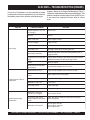
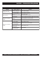
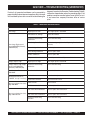
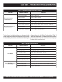
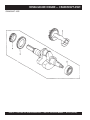
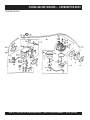
1
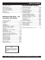
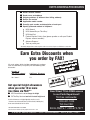
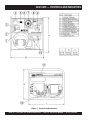
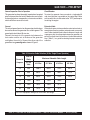
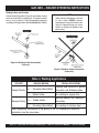
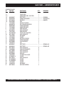
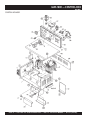
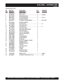
PARTS AND OPERATION MANUAL
© COPYRIGHT 2004, MULTIQUIP INC.
MULTIQUIP
Model GLW-180H
D.C. WELDER
A.C. GENERATOR
Revision #5 (03/14/05)
MULTIQUIP INC..
PARTS DEPARTMENT:
18910 WILMINGTON AVE.
800-427-1244
CARSON, CALIFORNIA 90746 FAX: 800-672-7877
SERVICE DEPARTMENT/TECHNICAL ASSISTANCE:
310-537-3700
800-421-1244
800-478-1244
FAX: 310-537-3927
FAX: 310-631-5032
E-mail:[email protected] • www:multiquip.com
Atlanta • Boise • Dallas • Houston • Newark
Montreal, Canada • Manchester, UK
Rio De Janiero, Brazil • Guadalajara, Mexico
WARNING
CALIFORNIA
Proposition 65 Warning
This product contains or produces chemicals known to
the State of California to cause cancer and birth defects
(or other reproductive harm).
DCL160
PAGE 2 — GLW-180H A.C. GENERATOR/WELDER — PARTS & OPERATION MANUAL — REV. #5 (03/14/05)
HERE'S HOW TO GET HELP
PLEASE HAVE THE MODEL AND SERIAL NUMBER
ON-HAND WHEN CALLING
PARTS DEPARTMENT
800-427-1244 or 310-537-3700
FAX: 800-672-7877 or 310-637-3284
SERVICE DEPARTMENT/TECHNICAL ASSISTANCE
800-478-1244 or 310-537-3700
FAX: 310- 537-4259
WARRANTY DEPARTMENT
888-661-4279, or 310-661-4279
FAX: 310- 537-1173
MAIN
800-421-1244 or 310-537-3700
FAX: 310-537-3927
GLW-180H A.C. GENERATOR/WELDER — PARTS & OPERATION MANUAL — REV. #5 (03/14/05) — PAGE 3
TABLE OF CONTENTS
Here's How To Get Help ............................................ 3
Table Of Contents ..................................................... 4
Parts Ordering Procedures ....................................... 5
Rules For Safe Operation ......................................... 6
Operation and Safety Decals .................................... 7
Specifications ............................................................ 8
General Information .................................................. 9
Multiquip GLW-180H — AC
Generator And Welder
Controls and Indicators ........................................... 10
Instrumentation ....................................................... 11
Installation .......................................................... 12-13
Pre-Setup ........................................................... 14-15
Load Application ..................................................... 16
Operating Instructions (Generator) ........................ 17
Operating Instructions (Welder)......................... 18-19
Maintenance ........................................................... 20
Preparation For Long Term Storage ....................... 21
Wiring Diagram ....................................................... 22
Troubleshooting (Engine) ................................... 23-24
Troubleshooting (Generator/Welder) ................. 25-26
Explanation Of Codes In Remarks Column ............ 28
Suggested Spare Parts ........................................... 29
Generator Assembly .......................................... 30-31
Control Box Assembly ........................................ 32-33
Control Box Assembly ........................................ 34-35
Pipe Frame Assembly ........................................ 36-37
Muffler Assembly ............................................... 38-39
Nameplate and Decals....................................... 40-41
Honda GX340K1 Engine
Cylinder Head Assembly ....................................42-43
Recoil Starter Assembly.....................................44-45
Fan Cover Assembly ..........................................46-47
Camshaft/Valves Assembly ................................48-49
Piston/Rings Assembly.......................................50-51
Air Cleaner Assembly.........................................52-53
Cylinder Barrel (Recoil) Assembly .....................54-55
Cylinder Barrel (Electric) Assembly ...................56-57
Crankcase Cover/Governor Assembly ..............58-59
Flywheel/Fan Assembly .....................................60-61
Coil Assembly.....................................................62-63
Crankshaft Assembly .........................................64-65
Electric Start Assembly ......................................66-67
Governor Controls Assembly .............................68-69
Carburetor Assembly .........................................70-71
Solenoid Assembly .............................................72-73
Fuel Cock Assembly ..........................................74-75
Terms and Conditions Of Sale — Parts .................. 76
NOTE
Specification and part number
are subject to change without
notice.
PAGE 4 — GLW-180H A.C. GENERATOR/WELDER — PARTS & OPERATION MANUAL — REV. #5 (03/14/05)
PARTS ORDERING PROCEDURES
■
■
■
■
■
■
■
Dealer account number
Dealer name and address
Shipping address (if different than billing address)
Return fax number
Applicable model number
Quantity, part number and description of each part
Specify preferred method of shipment:
•
•
•
•
UPS Ground
UPS Second Day or Third Day*
UPS Next Day*
Federal Express Priority One (please provide us with your Federal
Express account number)*
•
•
Airborne Express*
Truck or parcel post
*Normally shipped the same day the order is received, if prior to 2PM west coast time.
Earn Extra Discounts when
you order by FAX!
All parts orders which include complete part numbers
and are received by fax qualify for the following extra
discounts:
Number of
line items ordered
1-9 items
Additional Discount
3%
10+ items**
5%
Get special freight allowances
when you order 10 or more
line items via FAX!**
■ UPS Ground Service at no charge for freight
■ PS Third Day Service at one-half of actual freight cost
No other allowances on freight shipped by any other carrier.
**Common nuts, bolts and washers (all items under $1.00 list price)
do not count towards the 10+ line items.
*DISCOUNTS ARE SUBJECT TO CHANGE*
ount
c
s
i
D
Fax
Extra
c USA
i
t
s
e
m
for Do
Only
s
r
e
l
Dea
Now! Direct TOLL-FREE access
to our Parts Department!
Toll-free nationwide:
800-421-1244
Toll-free FAX:
800/6-PARTS-7 • 800-672-7877
Fax order discount and UPS special programs revised June 1, 1995
GLW-180H A.C. GENERATOR/WELDER — PARTS & OPERATION MANUAL — REV. #5 (03/14/05) — PAGE 5
RULES FOR SAFE OPERATION
CAUTION:
Failure to follow instructions in this manual
may lead to serious injury or even death! This
equipment is to be operated by trained and
qualified personnel only! This equipment is
for industrial use only.
The following safety guidelines should always be used when
operating the GLW-180H Generator/Welder:
GENERAL SAFETY
■ DO NOT operate or service this equipment before reading
this entire manual.
■ This equipment should not be operated by persons under 18
years of age.
■ NEVER operate this equipment without proper protective
clothing, shatterproof glasses, steel-toed boots and other
protective devices required by the job.
■ Provide adequate ventilation when operating the generator.
DO NOT operate the generator in any enclosed or narrow
space. The generator's GLWsoline engine gives off DEADLY
carbon monoxide GLWs.
■ NEVER operate the generator in an explosive atmosphere or
near combustible materials. An explosion or fire could result
causing severe bodily harm or even death.
■ Always make sure that the generator is secure on level ground
so that it cannot slide or shift around, endangering workers.
Also keep the immediate area free of bystanders.
■ When using a concrete vibrator or a similar device that is
immersed in a water based solution, make sure the device is
equipped with short circuit protection.
■ Always use rubber boots and gloves when operating a
concrete vibrator or similar device.
■ Use adequate size connecting cable for extension.
■ This generator is a source of potentially LETHAL high voltage.
Never permit unqualified personnel-especially children to
operate the generator.
■ Maintain electrical cords in good condition and frequently
replace the entire cable of the concrete vibrator with a new
one.
■ Always refuel in a well-ventilated area, away from sparks and
open flames.
■ High Temperatures – Allow the machine and engine to cool
before adding fuel or performing service and maintenance
functions. Contact with hot components can cause serious
burns.
■ Always use extreme caution when working with flammable
liquids. When refueling, stop the engine and allow it to cool.
DO NOT smoke around or near the machine. Fire or explosion
could result from fuel vapors, or if fuel is spilled on a hot
engine.
■ This generator is equipped with a ground terminal for your
protection. Always complete the grounding path from the
generator to an external grounding source.
■ NEVER operate this generator, or handle any electrical
equipment while standing in water, while bare foot, while
hands are wet, or in the rain. Electrical shock could occur
causing severe bodily harm or even death.
■ Keep electrical cords in good condition. Worn, bare or frayed
wiring can cause electrical shock, leading to bodily harm or
even death.
■ This generator requires an adequate free flow of cooling air.
Never operate the generator in any enclosed or narrow area
where free flow of the air is restricted. If the air flow is restricted
it will cause serious damage to the generator and may cause
injury to people.
■ NEVER touch the hot exhaust manifold, muffler or cylinder.
Allow these parts to cool before servicing generator.
Emergencies
■ Always know the location of the nearest fire extinguisher
and first aid kit. Know the location of the nearest telephone.
Also know the phone numbers of the nearest ambulance,
doctor and fire department. This information will be
invaluable in the case of an emergency.
Maintenance Safety
■ NEVER lubricate components or attempt service on a running
machine.
■ Always allow the machine a proper amount of time to cool
before servicing.
■ Keep the machinery in proper running condition.
■ Fix damage to the machine immediately and always replace
broken parts.
■ Dispose of hazardous waste properly. Examples of potentially
hazardous waste are used motor oil, fuel and fuel filters.
■ DO NOT use food or plastic containers to dispose of
hazardous waste.
■ DO NOT pour waste, oil or fuel directly onto the ground,
down a drain or into any water source
PAGE 6 — GLW-180H A.C. GENERATOR/WELDER — PARTS & OPERATION MANUAL — REV. #5 (03/14/05)
OPERATION AND SAFETY DECALS
Machine Safety Decals
The GLW-180H portable generator is equipped with a number of safety decals. These decals are provided for operator safety and
maintenance information. The illustration below shows these decals as they appear on the machine. Should any of these decals
become unreadable, replacements can be obtained from your dealer.
GLW-180H A.C. GENERATOR/WELDER — PARTS & OPERATION MANUAL — REV. #5 (03/14/05) — PAGE 7
GLW-180H — SPECIFICATIONS
Table 1. Specifications GLW-180H
Max. Current
180 Amps
Rated Voltage
26.4 Volts
Duty Cycle
50%
Welder
Adjustable Current Range
Rated Current
Applicable Electrode Size
Type Alternator
60 Cycle Generator
2-pole, Brushless Type Revolving Field
Rated Output (continuous)
4000 Watts
Rated Voltage
120 VAC
Rated Current
33.3 Amps
Single Phase (3-wire)
60 Hz
Rated Speed
3600 RPM
Power Factor
100%
Model
Honda GX340K1VD
Type
Air-cooled 4 stroke OVH 25° inclinded cylinder
Bore X Stroke
3.23 in. X 2.52 in.
(82 mm X 64 mm)
Displacement
20.63 cc
Max Output
Fuel Tank Capacity
Fuel
Lube Oil Capacity
Speed Control Method
Starting Method
Dry Net Weight
5/64" - 5/32"
4500 Watts
Frequency
Dimension (LXWXH)
160 Amps
Max. Output
Phase
Engine
50-180 Amps
8.0 H.P./3600 R.P.M.
Approx. 3-3/4 U.S. Gallons
Unleaded Automobile Gasoline
1-3/4 pints
Centrifugal Fly-weight Type
Recoil Start
31.5 x 22 x 22 in.
(800 x 560 x 560 mm.)
297 lbs. (135 Kg.)
Effects of Altitude and Heat
The maximum output of the engine listed above is applicable to supplying electrical power for continuous service at ambient
conditions in accordance with SAE Test cord J607. The above ambient conditions are at standard sea level, with a barometric
reading of 29.92 inches and a temperature of 60 degrees fahrenheit.
Generally, the engine output power will decrease 3-1/2% for each 1000 feet of altitude above sea level, and 1% for each 10° F
fahrenheit above the standard temperature of 60° F .
PAGE 8 — GLW-180H A.C. GENERATOR/WELDER — PARTS & OPERATION MANUAL — REV. #5 (03/14/05)
GLW-180H — GENERAL INFORMATION
WARNING:
Before connecting this generator to
any building’s electrical system, a
licensed electrician must install an
isolation (transfer) switch.
Serious injury or death may result
without this transfer switch.
GLW-180H FAMILIARIZATION
Generator/Welder
The Multiquip Model GLW-180H generator has been designed
as a portable lightweight power source for 60 Hz (singlephase) vibrators, lighting facilities, power tools, submersible
pumps and other industrial and construction machinery.
This generator is powered by a HONDA GLWsoline engine.
The alternator, a brushless revolving-field type, is
permanently aligned to the engine through rigid coupling.
The generator is mounted on rubber vibration isolators that
have a steel base backplate which is attached to the
protective steel pipe carrying frame. The protective carrying
frame is made of steel tubing and fully wraps around the
generator to protect aGLWinst damage.
This portable generator is supplied with a electrical control
box. To reduce vibration caused by the engine, the control
box is also placed on rubber isolators.
Control Box
The control box has the following: (all outputs are 60 Hz,
single phase)
z One 120V output receptacle.
z One 120V output receptacle (GFCI protected).
z One main 40 amp circuit breaker.
z AC Voltmeter
Excitation System
All GLW-series generators use a magnet attached to a
flywheel to produce AC voltage from a lamp coil beneath
the flywheel. As the magnet passes the coil it produces
approximately 19-22 AC volts.
This voltage (19-22 VAC) is then sent to the control box that
contains three rectifying diodes:
z Excitation (diode 1)
z Battery (diode 2)
z Slow Down (diode 3)
The AC voltage will pass through the excitation diode that
converts the voltage to DC power.
This DC power is then sent to the excitation windings housed
within the main windings commonly called the "stator".
This voltage is then transferred into the rotor through
induction. The rotor contains two diodes within it which rectify
the DC voltage and send it out through the main windings,
as AC voltage.
Engine
The four-cycle air-cooled HONDA GLWsoline engine is
designed to meet every performance requirement of this
generator. Reference Table 1, page 8 for engine
specifications.
Figure 1 (page 10) shows the basic controls and indicators
for the GLW-180H generator.
Idle Control Switch
DO NOT use the idle control switch in conjunction with AC
electro-magnetic switches relays etc. Using the idle control switch
with these devices will cause the idle control device not to actuate.
If any of these devices are being used, leave the idle control
switch in the OFF position.
When running capacitor start motors such as submersible
pumps, the idle control switch should NOT BE USED.
Disconnect the pump or tool from the power source by
switching OFF the main circuit breaker.
z Idle Control Switch
z Operation Switch
z Output Terminals (Welding)
NOTE
In keeping with Multiquip's policy of
constantly improving its products, the
specifications quoted herein are subject
to change without prior notice.
GLW-180H A.C. GENERATOR/WELDER — PARTS & OPERATION MANUAL — REV. #5 (03/14/05) — PAGE 9
GLW-180H — CONTROLS AND INDICATORS
Figure 1. Controls and Indicators
PAGE 10 — GLW-180H A.C. GENERATOR/WELDER — PARTS & OPERATION MANUAL — REV. #5 (03/14/05)
GLW-180H — INSTRUMENTATION
CAUTION :
When using a combination of dual
receptacles, total load should not exceed
the rated capacity of the generating.
7.
Current Regulator – Use this dial to adjust the welder's
output to the desired setting.
8.
Idle Control Switch – This unit is provided with an
automatic idle control for noise suppression and reduced
fuel consumption. The automatic idle control automatically
enGLWges under a no-load condition.
With the automatic idle control switched “ON”, the engine
revolutions will automatically drop to about 2500 rpm (lowspeed operation) within 3 seconds after the load stops.
The definitions below describe the controls and functions of the
of the GLW-180 H Generator/Welder.
1.
Ground Terminal Equipment – If required ground
equipment (power tools etc,) to this ground terminal. This
ground is not EARTH ground.
2.
120 VAC Twist Lock Receptacle – This unit is supplied
with one Twist Lock NEMA L5-30R (120V, 30 Amp)
output receptacle.
3.
120 VAC GFCI Receptacle – This unit is supplied with
one Duplex NEMA (GFCI) 5-20R (120V, 20 Amp) output
receptacle.
4.
AC Voltmeter – This voltmeter indicates (with a mark) the
rated 60 Hz, 120 VAC single phase output voltage. In
addition the voltmeter can also be used as a diagnostic
tool.
If the voltmeter indicator (needle) is below the rated voltage,
engine problems may exist (low/high RPM's). To prevent
damage to the generator or power tools turn the generator
OFF and consult your authorized Multiquip service dealer.
5.
Circuit Breaker – This single-pole, 40 amp breaker is
provided to protect both 120 VAC output receptacles from
overload.
6.
Operation Switch – Must be in the up position (ON) for
normal operation. To turn-off generator place this switch in
the down position (OFF).
When the operation is resumed, the engine speed is
automatically increased to about 3600 rpm (high-speed
operation) as soon as the load is connected.
9.
Current Regulator Selector Switch – Two position switch,
left position selects minimum current output (min.-130
amps), right position selects maximum current output
(max.-180).
10. DC Output Terminals – Connect the welder's (+) and (-)
welding cables to these terminals.
11. Fuel Tank – The fuel GLWuge is located on the fuel tank
and allows easy monitoring of the fuel level.
12. Chassis Ground – Connect earth ground (ground rod)
to this lug. See Figure 3.
CAUTION :
When AC power is required, ALWAYS
place the current regulator dial in the AC
power using range.
CAUTION :
NEVER turn the load ON or OFF by
connecting and disconnecting the load
power cord from the generator's AC output
receptacle. ALWAYS turn the circuit
breaker OFF to remove power from the
120 AC recepracles (load).
Figure 2. Current Regulator Switch
AC Power Range
GLW-180H A.C. GENERATOR/WELDER — PARTS & OPERATION MANUAL — REV. #5 (03/14/05) — PAGE 11
GLW-180H — INSTALLATION
Outdoor Installation
Install the generator in a location where it will not be exposed to
rain or sunshine. Make sure that the generator is on secure level
ground so that it cannot slide or shift around. Also install the
generator in a manner so that the exhaust will not be discharged
in the direction of nearby homes.
The installation site must be relatively free from moisture and
dust. All electrical equipment should be protected from excessive
moisture. Failure to do will result in deterioration of the insulation
and will result in short circuits and grounding.
Foreign materials such as dust, sand, lint and abrasive materials
have a tendency to cause excessive wear, not only to the engine
parts, but also to the alternator parts.
CAUTION :
An electric shock is apt to happen when
vibrators are used. Pay close attention to
handling when operating vibrators and
always use rubber boots and gloves to
insulate the body from a short circuit.
Generator Grounding
To guard aGLWnist electrical shock and possible damage to
the equipment, it is important to provide a good EARTH
ground.
Article 250 (Grounding) of the National Electrical Code (NEC)
provides guide lines for proper grounding and specifies that
the cable ground shall be connected to the grounding system
of the building (Figure 3) as close to the point of cable entry
as practical.
CAUTION :
NEC articles 250-91a and 250-95 set the following grounding
requirements:
Pay close attention to ventilation when
operating the generator inside confined
areas. The engine exhaust contains
noxious elements.
Indoor Installation
Exhaust GLWses from GLWsoline engines are extremely
poisonous. Whenever an engine is installed indoors the
exhaust fumes must be vented to the outside. The engine
should be installed at least two feet from any outside wall.
Using an exhaust pipe which is too long or too small can
cause excessive back pressure which will cause the engine
to heat excessively and possibly burn the valves
1. Use one of the following wire types to connect the
generator to earth ground.
Eliminate the danger of deadly carbon monoxide GLWs.
Remember that exhaust fumes from any GLWsoline engine
are very poisonous if discharged in a closed room, but
harmless if allowed to mix with the outside air. If the generator
is installed indoors, you must make provisions for venting
the engine exhaust to the outside of the building.
a. Copper - 10 AWG (5.3 mm2) or larger.
b. Aluminum - 8 AWG (8.4 mm2) or larger.
2. When grounding the generator (Figure 3) connect the
ground cable between the lock washer and the nut on
the generator and tighten the nut fully. Connect the other
end of the ground cable to earth ground.
3. NEC article 250-83c specifies that the earth ground rod
should be buried a minimum of 8 ft. into the ground.
NOTE
When connecting the generator to
any buildings electrical system
ALWAYS consult with a licensed
electrician.
PAGE 12 — GLW-180H A.C. GENERATOR/WELDER — PARTS & OPERATION MANUAL — REV. #5 (03/14/05)
GLW-180H — INSTALLATION
Grounding
Figure 3. Generator Ground Rod Application
GLW-180H A.C. GENERATOR/WELDER — PARTS & OPERATION MANUAL — REV. #5 (03/14/05) — PAGE 13
GLW-180H — PRE-SETUP
General Inspection Prior to Operation
Circuit Breaker
This generator has been thoroughly inspected and accepted
prior to shipment from the factory. However, be sure to check
for damaged parts or components, or loose nuts and bolts,
which could have occurred in transit.
To protect the generator from an overload, a single-pole 40
amp circuit breaker is provided on the control box. Make
sure to switch this circuit breaker to the "OFF" position prior
to starting the engine.
Ground
Extension Cable
The nut and ground terminal on the generator should always
be used to connect the generator to a suitable ground. The
ground path should be of #8 size wire.
When electric power is to be provided to various tools or loads at
some distance from the generator, extension cords are normally
used. Cables should be sized to allow for distance in length and
amperage so that the voltage drop between the generator and
point of use (load) is held to a minimum. Use the cable selection
chart (Table 2 ) as a guide for selecting the proper extension
cable size.
Connect the terminal of the ground wire between the
lock washer and the nut at the base of the generator
and tighten the nut fully. Connect the other end of the
ground wire to a grounding rod as shown in Figure 3.
Table 2. Extension Cable Selection (60 Hz, Single Phase Operation)
Current in
Amperes
Load In
Watts
Maximum Allowable Cable Length
At 1 2 0
Volts
#10 Wire
#12 Wire
#14 Wire
#16 Wire
2.5
300
1000 ft.
6 0 0 ft .
375 ft.
250 ft.
5
600
500 ft.
300 ft.
200 ft.
1 2 5 ft .
7.5
900
350 ft.
2 0 0 ft .
125 ft.
1 0 0 ft .
10
1200
250 ft.
150 ft.
100 ft.
15
1800
150 ft.
1 0 0 ft .
65 ft.
20
2400
125 ft.
7 5 ft .
5 0 ft.
CAUTION: Equipment damage can result from low voltage.
PAGE 14 — GLW-180H A.C. GENERATOR/WELDER — PARTS & OPERATION MANUAL — REV. #5 (03/14/05)
GLW-180H — PRE-SETUP
Lubrication Oil
Fuel
Fill the engine crankcase with lubricating oil through the filler
hole, but do not overfill. Make sure the generator is level.
With the dipstick inserted all the way, but without being screw
into the filler hole, verify that the oil level is maintained
between the two notches on the dipstick.
Close the fuel cock before filling the tank. Fill the fuel tank
with clean and fresh unleaded GLWsoline. DO NOT fill the
tank beyond capacity.
The oil listed in Table 3 is recommended to ensure better
engine performance. Use class SC or higher grade motor
oil.
Table 3. Recommended Motor Oil
Temperature Range
Type Oil
104° F ~ 23° F
(40° C ~ -5°C)
SAE 30
23° F ~ 5° F
(-5° C ~ -15°C)
SAE 20 or sae 10W-30
Below 5° C (-15°)
SAE 10W or SAE 10W-30
Pay attention to the fuel tank capacity when replenishing
fuel. Refer to the fuel tank capacity listed on page 8
Specification Table 1.
The fuel tank cap must be closed tightly after filling.
Handle fuel in a safety container. If the container does not have
a spout, use a funnel.
CAUTION :
Never fill the fuel tank while the engine is
running or in the dark. GLWsoline spillage
on a hot engine can cause a fire or
explosion. If GLWsoline spillage occurs,
wipe up the spilled GLWsoline completely
to prevent fire hazards.
GLW-180H A.C. GENERATOR/WELDER — PARTS & OPERATION MANUAL — REV. #5 (03/14/05) — PAGE 15
GLW-180H — LOAD APPLICATION
Single Phase Load
Always be sure to check the nameplate on the generator
and equipment to insure the wattage, amperage and
frequency requirements are satisfactorily supplied by the
generator for operating the equipment.
Generally, the wattage listed on the nameplate of the
equipment is its rated output. Equipment may require 130—
150% more wattage than the rating on the nameplate, as
the wattage is influenced by the efficiency, power factor and
starting system of the equipment.
NOTE
If wattage is not given on the equipment's
name plate, approximate wattage may be
determined by multiplying nameplate
voltage by the nameplate amperage.
WATTS = VOLTAGE x AMPERAGE
CAUTION:
Motors and motor-driven equipment draw
much greater current for starting than
during operation.
An inadequate size connecting cable which cannot carry
the required load can cause a voltage drop which can burn
out the appliance or tool and overheat the cable.
The idle control is operated at minimum load capacity of
100W. If the load capacity is less than 100W, throw the idle
control switch to the OFF position.
To determine the running wattage for your load, multiply the
running wattage as indicated by steps 1, 2, and 3 below:
1.
INCANDESCENT LOADS
Lights, heaters and similar appliances.
Total the running wattage and multiply by 1.
Example:
29 light bulbs @ 100W each = 2.9 KW
use a 3 KW generator.
2.
SMALL MOTORS
Drills and other small power tools.
Total the running wattage and multiply by 2.
Example:
A 1 inch drill runs at 1 KW
use a 2 KW generator.
3.
LARGE MOTORS
Submersible pumps, table saws etc.
Total the running wattage and multiply by 3.
Example:
A conveyor belt runs at 8 KW
use a 24 KW generator.
PAGE 16 — GLW-180H A.C. GENERATOR/WELDER — PARTS & OPERATION MANUAL — REV. #5 (03/14/05)
GLW-180H — GENERATOR OPERATING INSTRUCTIONS
Before Starting
1. Be sure to disconnect the electrical load and switch the
main circuit breaker to the “OFF” position prior to starting
the engine.
2. Never start the engine with the main circuit breaker “ON”.
3. Check the lubricating oil level prior to starting the engine.
Make sure the generator is level. The oil level must be
maintained between two notches on the dipstick.
4. When there is not enough lubricating oil, fill the crankcase
with high grade motor oil. Use a high quality detergent
oil classified SC, SD or SE. (See Table 3 on page 15)
Warm up
1. When the engine starts, open the choke slowly.
2. Run the engine at low speed for 3 minutes without load
until the engine warms up.
3. Turn the idle control switch to the "OFF" (down) position
and check the voltage by referring to the voltmeter on
the control box.
CAUTION:
DO NOT change the engine speed control
lever which has been set at the factory prior
to shipping.
CAUTION:
z NEVER start the engine when the oil level
is below the lower mark on the dipstick.
1. Check the generator for abnormal noise and smells. Then
connect the load to the receptacles of the generator.
z Check the fuel level on the fuel GLWuge.
When fuel is low, fill the fuel tank with
clean fresh unleaded automotive
GLWsoline.
2. Switch the main circuit breaker to the “ON” position and
turn the idle control switch to the “ON” (down) position
for normal (load) engine operation.
Operation
z If GLWsoline spillage occurs, completely
Starting
wipe up the spilled GLWsoline.
1. Place the idle control switch in the “ON” (up) position.
2. Close the choke. Adjust the opening of the choke valve
according to operating conditions. When the engine is
warm or the air temperature is high, close the choke
valve halfway or open it all the way.
3. Confirm that the main circuit breaker on the generator
control box is “OFF”.
4. Set the operation switch to the “ON” position and grasp
the starting rope and slowly pull it out. The resistance
becomes hardest at a certain position, corresponding
to the compression point. Rewind the rope a little from
that point and pull out sharply.
5. If the engine fails to start, repeat the procedure.
CAUTION:
z DO NOT pull the starter rope all the way
to the end.
z DO NOT release the starter rope after
pulling. Allow it to rewind as soon as
possible.
Check the voltage by referring to the voltmeter on the control
box. When the voltmeter indicates 120 volts, 120 volts from
the 120V receptacles and 240 volts from the 240V receptacle
can be obtained at the same time. Refer to Figure 1, Controls
and Indicators, item 4 on page 10.
Stopping the Engine
CAUTION:
NEVER stop the engine suddenly while
running at high speeds.
1. Remove the load from the generator. Place the circuit
breaker in the “OFF” position. Refer to Figure 1, item 5
on page 10. Run the engine (no-load) with the idle control
switch set to the ON position for three to five minutes,
then stop the engine.
2. Turn the START/STOP switch to the “STOP” position.
3. Never stop the engine suddenly while running at high
speed.
4. Close the fuel cock.
GLW-180H A.C. GENERATOR/WELDER — PARTS & OPERATION MANUAL — REV. #5 (03/14/05) — PAGE 17
GLW-180H — WELDER OPERATING INSTRUCTIONS
Welding Cables and Polarities
Connect the welding cables (Figure 4) to the welder's output
terminals located on the control panel. The output terminals
have (+) and (-) polarities. Select the appropriate polarities
according to the application (See Welding Application, Table 5).
NOTE
Attach terminal connectors at the end
of each cable. NEVER connect
exposed wires (Figure 5) directly to the
terminal. Exposed wiring may cause
shocks or di-electric breakdown from
poor contact.
Figure 4. Welding Cable Connection
(Correct)
Figure 5. Welding Cable Connection
(Incorrect)
Table 4. Welding Applications
POLARITY
Straight Polarity
Reverse Polarity
WELDING METHOD
TYPICAL APPLICATIONS
(+) ... Grounding (Base Metal)
Welding steel materials for general
structures, and thickness plates.
(-) ... Welder Holder
Arc welding for copper alloy
(+) ... Welder Holder
Build-up welding, ARC welding of
thin plates
(+) ... Grounding (Base Metal)
Arc welding of stainless steel
Note: Reguarding the selection of the polarity in the CV character tics, follow the
instructions from the wire maker.
PAGE 18 — GLW-180H A.C. GENERATOR/WELDER — PARTS & OPERATION MANUAL — REV. #5 (03/14/05)
GLW-180H — WELDER OPERATING INSTRUCTIONS
Welding Cables
Duty Cycle
The required cable welding size is governed by this simple
rule: The longer the welding cable, or the greater the welding
current, the thicker (copper strands) the calbe must be.
The duty cycle for the generator/welder is based on 10 minute
intervals. See Table 6 below.
Table 6. Duty Cycle
Select a welding cable with adequate thickness according
to the cable length and welding amperage (current) as listed
in Table 5.
Table 5. Welder Cable Sizes
Welder Output
Current
100
150
200
Cable Length
Cable Size
50
No. 3
100
No. 3
125
No. 3
150
No. 3
200
No. 3
250
No. 3
300
No. 3
50
No. 3
100
No. 3
125
No. 3
150
No. 3
200
No. 2
250
No. 1
300
No. 1
50
No. 3
100
No. 3
125
No. 3
150
No. 2
200
No. 1
250
No. 1/0
300
No. 1/0
CAUTION:
To prevent serious accidents, ALWAYS turn
off the generator/welder ( operation switch)
and set the main circuit breaker to the OFF
position.
Welding
Current
110 or
L e ss
125
145
160
180
Duty
Cycle%
100
80
60
50
40
CAUTION:
NEVER switch the current range selector
switch during any welding operation.
1. Connect the welding cables (electrodes) to the
generator's output terminals (Figure 4). For minimum
welding current (min-130 amps), use an eyelet terminal
connector with a 5/64" to 1/8" diameter, for maximum
welding current (110 - max amps), use an eyelet terminal
connector with a 3/32" to 5/32" diameter
2. Set the current regulator control switch on the control
panel (Figure X) to the desired setting. The inner scale
is for low current, the outer scale is high current output.
Figure 6. Current Regulator/Range Switches
3. Set the current range control switch (Figure 7) to either
low or high. DO NOT change the position of this switch
while welding.
GLW-180H A.C. GENERATOR/WELDER — PARTS & OPERATION MANUAL — REV. #5 (03/14/05) — PAGE 19
GLW-180H — MAINTENANCE
General Inspection
At least daily or prior to each use, the generating set should
be cleaned and inspected for deficiencies. Check for loose,
missing or damaged nuts, bolts or other fasteners. Also check
for fuel or oil leaks.
Service Daily
Engine Side (Refer to the Engine Instruction Manual)
Cleaning the Fuel Strainer
Check Oil Level
Clean the fuel strainer if it contains dust or water. Remove
dust or water in the strainer cap and wash it in GLWsoline.
Securely fasten the fuel strainer cap so that fuel will not
leak. Check the fuel strainer every 200 hours of operation or
once a month.
Check the crankcase oil level prior to each use, or when the
fuel tank is filled. Make sure the generating set is level. The
oil level must be between the two notches on the dipstick.
Changing Oil
Change oil after the first 20 hours of operation. Drain and
refill the engine crankcase every 50 operating hours or once
a week thereafter. Drain crankcase oil into a suitable container
while engine is still warm. Replace the drain plug tightly. Add
oil through the filler hole.
Air Cleaner
If engine is operating in very dusty and dry grass conditions.
A clogged air cleaner will result in high fuel consumption,
loss of power and excessive carbon buildup in the
combustion chamber.
Spark Plug
Remove carbon build-up on the spark plug (Figure 5) with a
wire brush. Set the spark plug GLWp to 0.6—0.7mm (0.0240.028 inch). Tighten with a spark plug socket wrench. Clean
the spark plug every 50 operating hours or once a week.
Every 50 hours: Remove air cleaner element (std. or heavy
duty types), and wash in kerosene or liquid detergent and
hot water. Wrap foam element in a cloth and squeeze dry.
Wipe heavy duty paper element dry with toweling. Saturate
element with kerosene; squeeze excess from foam element.
Wipe excess from heavy duty paper element.
Figure 5. Spark Plug GLWp
PAGE 20 — GLW-180H A.C. GENERATOR/WELDER — PARTS & OPERATION MANUAL — REV. #5 (03/14/05)
GLW-180H — PREPARATION FOR LONG -TERM STORAGE
Generator Storage
For storage of the generating set for over 30 days, the
following is required:
z Drain the fuel tank completely.
z Run the engine until the GLWsoline in the carburetor is
completely consumed.
z Completely drain the oil from the crankcase and refill
with fresh oil.
z Remove the spark plug, pour 2 or 3 cc of SAE 30 oil
into the cylinder and crank slowly to distribute the oil.
z Slowly rotate the engine a few times with the starter
Rope and install a new plug.
z Pull out the starter rope slowly and stop at the
compression point.
z Clean all external parts of the generating set with a cloth.
z Cover the generating set and store in a clean, dry place.
GLW-180H A.C. GENERATOR/WELDER — PARTS & OPERATION MANUAL — REV. #5 (03/14/05) — PAGE 21
GLW-180H — WIRING DIAGRAM GENERATOR/ ENGINE
GENERATOR
ENGINE
PAGE 22 — GLW-180H A.C. GENERATOR/WELDER — PARTS & OPERATION MANUAL — REV. #5 (03/14/05)
GLW-180H — TROUBLESHOOTING (ENGINE)
Practically all breakdowns can be prevented by proper
handling and maintenance inspections, but in the event of a
breakdown, please take a remedial action following the
diagnosis based on the Engine Troubleshooting (Table 7)
information shown below and on the proceeding page. If the
problem cannot be remedied, please leave the unit just as it
is and consult our company's business office or service
plant.
TABLE 7. ENGINE TROUBLESHOOTING
SYMPTOM
Poor star ting
Insufficient power output "no
compression"
Insufficient power output
"compression"
POSSIBLE PROBLEM
SOLUTION
Inspect carburetor to see if fuel
is reaching it?
Check fuel line
No Fuel?
A d d Fu e l
Water in fuel tank?
Flush or replace fuel tank.
Fuel filter clogged?
Replace fuel filter
Stuck carburetor?
Check float mechanism.
Spark plug is red?
Spark plug is fouled. Check tranistor ignition unit.
Spark plug is blue-white?
Insufficient compression, injected air leaking. Carburetor jets are
clogged (overflow).
No spark present at tip of spark
plug?
Tranistor ignition unit broken, high voltage cord cracked or broken.
Star t/Stop switch broken. Replace spark plug if fouled.
No oil?
Add oil as required.
Oil pressure alarm lamp blinks
upon star ting?
Check Automatic shutdown circuit "oil sensor".
Engine will not turn over?
Replace cylinder and piston and if necessary axel joint.
Cylinder head connecting bolts
loose?
Tighten cylinder head connecting bolts.
Cylinder head gasket damaged?
Replace cylinder head gasket.
Malfunction of valve seat?
Re-seat valves.
Spark plug is loose?
Replace spark plug.
Worn piston rings?
Replace piston rings.
Malfunction in air-cleaner
system, air filter clogged?
Clean or replace air filter.
Air leaking in from interface
between carburetor and cylinder
head?
Tighten bolts between carburetor and cylinder head. Replace
cylinder head gasket.
Malfunction in fuel system?
Clean or replace fuel filter.
Clean or replace carburetor.
Check carburetor float.
GLW-180H A.C. GENERATOR/WELDER — PARTS & OPERATION MANUAL — REV. #5 (03/14/05) — PAGE 23
GLW-180H — TROUBLESHOOTING (ENGINE)
TABLE 7. ENGINE TROUBLESHOOTING (CONTINUED)
SYMPTOM
Insufficient power output
"compression" and overheats
Burns to much fuel
Exhaust color is continiously
"WHITE"
Exhaust color is continiously
"BLACK"
POSSIBLE PROBLEM
SOLUTION
Malfunction in cooling fan?
Check or replace cooling fan.
Air in-take filter clogged?
Clean or replace air in-take filter.
Over accumulation of exhaust
products?
Clean and check valves.
Check muffler, replace if necessary.
Wrong spark plug?
Replace spark plug with manufactures suggested type spark plug.
Lubricating oil is wrong
viscosity?
Replace lubricating oil with correct viscosity.
Worn rings?
Replace rings
Air cleanner clogged?
Clean or replace air cleaner.
Choke valve has not been set
to the correct position?
Adjust choke valve to the correct position.
Carburetor defective, seal on
carburetor broken?
Replace carburetor or seal.
Poor carburetor adjustment
"engine runs too rich?
Adjust carburetor.
PAGE 24 — GLW-180H A.C. GENERATOR/WELDER — PARTS & OPERATION MANUAL — REV. #5 (03/14/05)
GLW-180H — TROUBLESHOOTING (GENERATOR)
Practically all generator breakdowns can be prevented by
proper handling and maintenance inspections, but in the event
of a breakdown, please take a remedial action following the
diagnosis based on the Generator Troubleshooting (Table 8)
information shown below and on the preceding page. If the
problem cannot be remedied, please leave the unit just as it
is and consult our company's business office or service
plant.
TABLE 8. GENERATOR TROUBLESHOOTING
SYMPTOM
Low voltage
POSSIBLE PROBLEM
SOLUTION
Engine speed too low?
Raise engine speed to rated RPM.
AC voltmeter not working?
Replace AC voltmeter.
Control box internal wiring
malfunction?
Check control box wiring.
Defective ignition coil?
Check red and green ignition wires. Replace ignition wires if
necessary.
Rotor winding malfunction?
Check or replace rotor.
Stator winding malfunction?
Check or replace stator.
Breaker malfunction?
Check or replace CB1.
Full power switch malfunction?
Check full power switch and full power switch circuit.
Voltage output too high.
Engine speed too high?
Lower engine speed to rated RPM.
Voltage output too high. Engine
speed normal 3650 RPM
(unloaded), 2500 RPM (idle)
Control box internal wiring
malfunction
Check control box wiring.
Circuit breaker will not turn on
"NO LOAD"
Defective circuit breaker?
Replace circuit breaker.
Overload?
Reduce load or replace breaker.
Load circuit is shor ted?
Check load circuit for shor t.
Stuck solenoid?
Check solenoid.
Bad Idle control switch?
Check or replace idle control switch.
Idle control switch malfunction?
Check or replace idle control switch.
Idle control device malfunction?
Check or replace idle control device.
Control box interal wiring
defective?
Check control box wiring.
Low voltage. Engine speed
normal 3650 RPM (unloaded),
2500 RPM (idle)
Circuit breaker will turn on
"LOADED" but trips immediately.
Does not accelerate from low to
high "NO LOAD"
Does not accelerate from low to
high "LOAD ACTIVE"
GLW-180H A.C. GENERATOR/WELDER — PARTS & OPERATION MANUAL — REV. #5 (03/14/05) — PAGE 25
GLW-180H — TROUBLESHOOTING (GENERATOR)
TABLE 8. GENERATOR TROUBLESHOOTING (CONTINUED)
SYMPTOM
Does not decelerate no
"VOLTAGE OUTPUT".
Does not decelerate but has
"VOLTAGE OUTPUT".
POSSIBLE PROBLEM
SOLUTION
Defective rotor windings?
Check or replace rotor.
Defective solenoid?
Check or replace solenoid.
Defective idle control device?
Check or replace idle control device.
Defective solenoid?
Check or replace idle control device.
Control box wiring malfunction?
Check control box wiring, replace any defective components.
Defective solenoid?
Check or replace solenoid.
Idle control device malfunction?
Check or replace idle control device.
Practically most welder breakdowns can be prevented by
proper handling and maintenance inspections, but in the event
of a breakdown, please take a remedial action following the
diagnosis based on the Welder Troubleshooting (Table 9)
information shown below . If the problem cannot be remedied,
please leave the unit just as it is and consult our company's
business office or service plant.
TABLE 9. WELDER TROUBLESHOOTING
SYMPTOM
POSSIBLE PROBLEM
SOLUTION
Loose or disconnected wires?
Visually check wires, replace if necessary.
Defective generator?
Check generator, replace if necessary.
Poor contactor contact?
Pull the lead wire and check for connection.
Defective rectifer Re4 or Re5?
Replace rectifer.
Defective exciter Field Assy?
Replace Field Assy.
Defective rectifer Re1 or Re2?
Replace rectifer.
Improper engine speed?
Adjust engine speed.
Improper welding cable?
Use welding cables with sufficient current capacity and length.
Improper current control?
Readjust to 50-180 amps.
No "ARCING"
Weak "ARCHING" and low
outout voltage.
PAGE 26 — GLW-180H A.C. GENERATOR/WELDER — PARTS & OPERATION MANUAL — REV. #5 (03/14/05)
NOTE PAGE
GLW-180H A.C. GENERATOR/WELDER — PARTS & OPERATION MANUAL — REV. #5 (03/14/05) — PAGE 27
GLW-180H — EXPLANATION OF CODE IN REMARKS COLUMN
How to read the marks and remarks used in this parts
book.
Items Found In the “Remarks” Column
Serial Numbers-Where indicated, this indicates a serial
number range (inclusive) where a particular part is used.
Model Number-Where indicated, this shows that the
corresponding part is utilized only with this specific model
number or model number variant.
Items Found In the “Items Number” Column
All parts with same symbol in the number column, , #, +, %, or
■, belong to the same assembly or kit.
*
NOTE
If more than one of the same reference number is
listed, the last one listed indicates newest (or latest)
part available.
NOTE
The contents of this catalog are
subject to change without notice.
PAGE 28 — GLW-180H A.C. GENERATOR/WELDER — PARTS & OPERATION MANUAL — REV. #5 (03/14/05)
GLW-180H — SUGGESTED SPARE PARTS
GLW-180H 1 TO 5 UNITS WITH HONDA
GX340K1EDN2 ENGINE
1 to 5 Units
Qty.
P/N
Description
5 ............ 9807955846 ......... SPARK PLUG
1 ............ 15510ZE2W01 ..... OIL LEVEL SWITCH
1 ............ 15600735700 ...... DIPSTICK
1 ............ 28400ZEZW01ZB RECOIL STARTER
5 ............ 17211899000 ...... ELEMENT AIR
1 ............ 16100ZEZF00 ..... CARBURETOR ASSY.
1 ............ 16950ZB4015 ....... FUEL COCK ASSY.
2 ............ 0810107103 .......... FUEL FILTER
2 ............ 0810106004 .......... CAP, FUEL TANK
1 ............ 0601805327 .......... CIRCUIT BREAKER
1 ............ 0601823204 .......... RECTIFIER
1 ............ 0601812597 .......... RECEPTACLE
1 ............ 0601811031 .......... RECEPTACLE, 125V, 30A
NOTE
Part numbers on this Suggested
Spare Parts List may supercede/
replace the P/N shown in the text
pages of this book.
GLW-180H A.C. GENERATOR/WELDER — PARTS & OPERATION MANUAL — REV. #5 (03/14/05) — PAGE 29
GLW-180H — GENERATOR ASSY.
GENERATOR ASSY.
PAGE 30 — GLW-180H A.C. GENERATOR/WELDER — PARTS & OPERATION MANUAL — REV. #5 (03/14/05)
GLW-180H — GENERATOR ASSY.
GENERATOR ASSY.
NO.
1
*1-1
*1-2
1-3
1-4
1-5
1-6
2
3
4
5
6
7
8
9
10
11
12
13
14
15
16
17
18
19
20
21
22
23
24
25
26
27
28
29
30
31
PART NO.
1971005003
0601820037
0601822640
0071206304
3051070003
1971018004
0801086104
0040010000
1971345003
1971315502
0012308025
7851315402
D2137000103
0017106025
1961324003
1971336004
7911316004
0040008000
0041208000
1961844513
0601820012
0601820013
0017105016
1031890004
0017108035
0019008016
0207208000
1001843504
D1153500114
0017105010
D1153500603
D1153500503
1971331003
1031863104
0027105010
PART NAME
QTY.
REMARKS
ROTOR ASSY.
1
FIELD ASSY.
1
ARMATURE ASSY., EXCITER
1
RECTIFIER ........................................... 1 ............. S10VB60
SURGE ABSORBER ............................. 1 ............. TNR15G471K
BEARING .............................................. 1 ............. 6304DDU
FAN
1
SET BOLT ROTOR
1
SET WASHER BEARING
1
SPRING WASHER
1
ARMATURE ASSY.
1
END BRACKET
1
HEX HEAD BOLT
4
END BRACKET
1
FIELD ASSY. EXCITER
1
HEX HEAD BOLT
4
GROMMET
1
COVER
1
SET BOLT STATOR
4
SPRING WASHER
4
PLAIN WASHER
4
FIN
2
RECTIFIER ........................................... 1 ............. SR30MA- 6S
RECTIFIER ........................................... 1 ............. SR30MA- 6R
HEX HEAD BOLT
8
INSULATOR WASHER
8
HEX HEAD BOLT
4
HEX HEAD BOLT
2
HEX NUT
2
CONNECTION PLATE
6
COVER
2
HEX HEAD BOLT
4
COVER
2
COVER
2
COVER
1
GROMMET
1
MACHINE SCREW
4
GLW-180H A.C. GENERATOR/WELDER — PARTS & OPERATION MANUAL — REV. #5 (03/14/05) — PAGE 31
GLW-180H — CONTROL BOX
ASSY.
CONTROL BOX ASSY.
PAGE 32 — GLW-180H A.C. GENERATOR/WELDER — PARTS & OPERATION MANUAL — REV. #5 (03/14/05)
GLW-180H — CONTROL BOX
ASSY.
CONTROL BOX ASSY.
NO.
1
1-1
2
3
4
5
6
7
8
9
10
11
12
13
14
15
16
17
18
19
20
21
22
23
24
25
26
27
28
PART NO.
1971811002
0226900215
0601823204
0027103016
0800235101
0027104020
0601804211
0027104010
1971885003
0017106016
1971880003
0017106016
1971811404
0017105016
0801831204A
0801880004
0039510000
0042710000
0045110000
0037810000
1971865103
1971866004
0805088004
0805088304
0017106020
0207006000
1971805204
0017105016
1971811103
1970501002
0601803021
PART NAME
QTY.
REMARKS
CONTROL BOX
1
EDGE COVER
1
RECTIFIER ........................................... 3 ............. S5VB60
MACHINE SCREW
3
SLOW DOWN UNIT............................... 1 ............. NC- 54
MACHINE SCREW
2
CURRENT TRANSFORMER ................. 1 ............. MCT-100Y
MACHINE SCREW
2
DC REACTOR ....................................... 1 ............. L2
HEX HEAD BOLT
4
AC REACTOR ....................................... 1 ............. L1
HEX HEAD BOLT
4
HEAT INSULATOR PANEL
1
HEX HEAD BOLT
2
OUT PUT TERMINAL
2
INSULATOR WASHER
2
HEX NUT
4
PLAIN WASHER
4
WAVE WASHER
4
WING NUT
2
OUTPUT TERMINAL COVER
1
RUBBER SHEET
1
RUBBER WASHER
2
COLLAR
2
HEX HEAD BOLT
2
HEX NUT
2
COVER
1
HEX HEAD BOLT
2
CONTROL PANEL
1
NAME PLATE ........................................ 1 ............. N-5646
CURRENT RANGE SELECTOR ............ 1 ............. SW1
GLW-180H A.C. GENERATOR/WELDER — PARTS & OPERATION MANUAL — REV. #5 (03/14/05) — PAGE 33
GLW-180H — CONTROL BOX ASSY.
CONTROL BOX ASSY.
PAGE 34 — GLW-180H A.C. GENERATOR/WELDER — PARTS & OPERATION MANUAL — REV. #5 (03/14/05)
GLW-180H — CONTROL BOX ASSY.
CONTROL BOX ASSY.
NO.
29
30
31
32
33
34
35
36
37
38
39
40
41
42
43
44
45
46
47
48
49
50
PART NO.
8705945004
0027106016
1971835004
0021104010
0801800202
0050402525
0601800258
0601805306
3011816004
0027104010
0601812597
0601811031
0027104010
0207004000
0601815109
0601830727
0601830738
0017105016
1971811303
0017105016
1971811203
0017105016
0017108020
PART NAME
QTY.
REMARKS
SEAL
1
MACHINE SCREW
3
RHEOSTAT ............................................ 1 ............. VR 100W 48 OHM
MACHINE SCREW
3
KNOB
1
SPRING PIN
1
AC VOLTMETER ................................... 1 ............. 8283 0 ~120V, 240V
CIRCUIT BREAKER .............................. 1 ............. CB KM51 40A
CIRCUIT BREAKER BRACKET
1
MACHINE SCREW
2
RECEPTACLE ....................................... 1 ............. CON2 5- 20R
RECEPTACLE ....................................... 1 ............. CON1 L5- 30R REPL. 0601811035
MACHINE SCREW
4
HEX NUT
4
GROUND TERMINAL ............................ 1 ............. T- 381
IDLE CONTROL SWITCH ..................... 1 ............. SW2 ET115A12
OPERATION SWITCH ........................... 1 ............. ET210K12
HEX HEAD BOLT
4
CONTROL BOX PANEL
1
HEX HEAD BOLT
7
CONTROL BOX COVER
1
HEX HEAD BOLT
5
HEX HEAD BOLT
4
GLW-180H A.C. GENERATOR/WELDER — PARTS & OPERATION MANUAL — REV. #5 (03/14/05) — PAGE 35
GLW-180H — PIPE FRAME ASSY.
PIPE FRAME ASSY.
PAGE 36 — GLW-180H A.C. GENERATOR/WELDER — PARTS & OPERATION MANUAL — REV. #5 (03/14/05)
GLW-180H — PIPE FRAME ASSY.
PIPE FRAME ASSY.
NO.
1
2
3
4
5
6
7
8
9
10
11
12
13
14
14
15
16
17
18
19
20
21
22
23
24
25
PART NO.
1975401012
1975401103
3015419604
0207008000
1725419214
0207008000
0017108030
0207008000
0017108045
0207008000
7915455103
7855455003
0017106016
1975401304
0017106016
1975511002
1975511002MQ0
0810106004
0810107103
7855525514
7855525604
0017108030
0017108020
16950ZB4015
9500014519040
0605515096
1975401203
0017108020
PART NAME
QTY.
REMARKS
PIPE FRAME
1
BASE
1
RUBBER SUSPENSION
2
HEX NUT
4
RUBBER SUSPENSION
2
HEX NUT
4
HEX HEAD BOLT
2
HEX NUT
2
HEX HEAD BOLT
2
HEX NUT
2
COVER
1
COVER
1
HEX HEAD BOLT
6
STOPPER
1
HEX HEAD BOLT
2
TEAL/MINT GREEN FUEL TANK
1
ORANGE/RED FUEL TANK
1
CAP, FUEL TANK
1
FUEL FILTER
1
RUBBER CUSHION
2
COLLAR
2
HEX HEAD BOLT
2
HEX HEAD BOLT
2
FUEL COCK .......................................... 1 ............. REPLACES 0605511087
HOSE .................................................... 1 ............. REPLACES 0605513140
HOSE BAND 8
2
HEAT INSULATOR PANEL
1
HEX HEAD BOLT
1
GLW-180H A.C. GENERATOR/WELDER — PARTS & OPERATION MANUAL — REV. #5 (03/14/05) — PAGE 37
GLW-180H — MUFFLER ASSY.
MUFFLER ASSY.
PAGE 38 — GLW-180H A.C. GENERATOR/WELDER — PARTS & OPERATION MANUAL — REV. #5 (03/14/05)
GLW-180H — MUFFLER ASSY.
MUFFLER ASSY.
NO.
1
2
3
4
5
6
7
8
9
10
11
12
13
14
15
16
17
18
PART NO.
7852310003
18320ZC2000
18325ZB4000
18329ZB4000
18355ZB4630
90183671003
0017106012
18333ZB4800
957000802000
7855469004
0017108020
0017108020
7905469004
0017106020
0017106016
7905468004
7905468014
0017106012
0017106016
PART NAME
QTY.
REMARKS
MUFFLER
1
MUFFLER PROTECTOR ....................... 1 ............. 0602302001
MUFFLER PROTECTOR ....................... 1 ............. 0602302002
SEAL ..................................................... 2 ............. 0602302003
SPARK ARRESTOR .............................. 1 ............. 0602313060
TAPPING SCREW ................................. 1 ............. 0602322060
HEX HEAD BOLT
5
GLWSKET ............................................. 1 ............. 0602320175
HEX HEAD BOLT .................................. 2 ............. 0602322061
BRACKET
1
HEX HEAD BOLT
1
HEX HEAD BOLT
1
BRACKET
1
HEX HEAD BOLT
1
HEX HEAD BOLT
2
BRACKET ............................................. 1 ............. UP TO S/N. 4734153
BRACKET ............................................. 1 ............. FROM S/N.4734154
HEX HEAD BOLT
2
HEX HEAD BOLT
2
GLW-180H A.C. GENERATOR/WELDER — PARTS & OPERATION MANUAL — REV. #5 (03/14/05) — PAGE 39
GLW-180H — NAMEPLATE ASSY.
NAMEPLATE ASSY.
PAGE 40 — GLW-180H A.C. GENERATOR/WELDER — PARTS & OPERATION MANUAL — REV. #5 (03/14/05)
GLW-180H — NAMEPLATE ASSY.
NAMEPLATE ASSY.
NO
PART NO
PART NAME
1
2
3
4
5
6
7
8
9
10
0800628504
1980680004
7900638204
TBD
TBD
0820610804
0820610404
7900636004
8700611804
8700611904
DECAL : GROUND
DECAL : FUEL COCK
DECAL : OPERATING INSTRUCTIONS
DECAL : CURRENTRANGE CONTROL
DECAL : MQ GLW-180
DECAL : CAUTION
DECAL : WARNING
DECAL : OPERATE AT 3600 RPM ONLY
DECAL : WARNING
DECAL : DANGER
QTY.
1
1
1
1
1
1
1
1
1
1
REMARKS
S-1123
S-3704
S-4607
DSC01
S-4984
S-4985
SEE DECAL ILLUSTRATIONS ON PAGE 7.
GLW-180H A.C. GENERATOR/WELDER — PARTS & OPERATION MANUAL — REV. #5 (03/14/05) — PAGE 41
HONDA GX340K1 ENGINE — CYLINDER HEAD
CYLINDER HEAD ASSY.
HONDA GX240K1 ENGINE — CYLINDER HEAD
PAGE 42 — GLW-180H A.C. GENERATOR/WELDER — PARTS & OPERATION MANUAL — REV. #5 (03/14/05)
HONDA GX340K1 ENGINE — CYLINDER HEAD
CYLINDER HEAD ASSY.
NO
PART NO
PART NAME
1
2
3
4
5
6
7
8
9
10
11
12
13
14
15
16
17
122AOZF6W00
12204ZE2325
12205ZE2315
12216ZE2300
12251ZE3W00
12310ZE2010
12391ZE2010
18330ZE3700
18333ZE3800
90014ZE2000
90042ZE3700
90047ZE2000
90441ZE2010
9405008000
9430112200
957251008000
9807955846
9807955855
HEAD COMP., CYLNDER ........... 1 .......... INCLUDES ITEM W/
GUIDE, IN. VALVE (OVER SIZE) 1
GUIDE, EX. VALVE (OVER SIZE) 1
CLIP, VALVE GUIDE
2
GLWSKET, CYLINDER HEAD 1
COVER COMP., HEAD
1
PACKING, HEAD COVER
1
PIPE, EX.
1
GLWSKET, EX. PIPE
1
BOLT, HEAD COVER
1
BOLT, STUD, 8X98
2
BOLT, STUD, 8X47
2
WASHER COMP., HEAD COVER 1
NUT, FLANGE, 8MM
2
PIN, DOWEL, 12X20
2
BOLT, FLANGE, 10X80
4
PLUG, SPARK (BPR5ES NGK) 1
PLUG, SPARK (W16EPRU ND) 1
*
*
*
QTY.
REMARKS
*
1
GLW-180H A.C. GENERATOR/WELDER — PARTS & OPERATION MANUAL — REV. #5 (03/14/05) — PAGE 43
HONDA GX340K1 ENGINE — RECOIL STARTER
RECOIL STARTER ASSY.
PAGE 44 — GLW-180H A.C. GENERATOR/WELDER — PARTS & OPERATION MANUAL — REV. #5 (03/14/05)
HONDA GX340K1 ENGINE — RECOIL STARTER
RECOIL STARTER ASSY.
NO
PART NO
PART NAME
1
2
3
4
5
6
7
8
9
10
11
12
13
14
28400ZE3W01ZB
28410ZE3W01ZB
28421ZE3W01
28422ZE2W01
28441ZE2W01
28442ZE2W01
28443ZE2W01
28444ZE2W01
28445ZE2W01
28461ZE2W01
28462ZE3W01
28469ZE2W01
90004ZE2W01
957010600800
STARTER ASSY, RECOIL
CASE COMP., RECOIL STARTER
PULLEY, RECOIL STARTER
RATCHET, STARTER
SPRING, FRICTION
SPRING, STARTER RETURN
SPRING, RATCHET
RETAINER, SPRING
HOLDER, SPRING
GRIP, STARTER
ROPE, RECOIL STARTER
GRID REINFORCEMENT
SCREW, CENTER
BOLT, FLANGE, 6X8
*
*
*
*
*
*
*
*
*
*
*
*
QTY.
1
1
1
2
1
1
2
1
1
1
1
1
1
3
REMARKS
INCLUDES ITEMS W/
*
GLW-180H A.C. GENERATOR/WELDER — PARTS & OPERATION MANUAL — REV. #5 (03/14/05) — PAGE 45
HONDA GX340K1 ENGINE — FAN COVER
FAN COVER ASSY.
PAGE 46 — GLW-180H A.C. GENERATOR/WELDER — PARTS & OPERATION MANUAL — REV. #5 (03/14/05)
HONDA GX340K1 ENGINE — FAN COVER
FAN COVER ASSY.
NO
PART NO
PART NAME
1
2
3
4
5
19610ZE3700ZB
19631ZE3W00
81329567020
90013883000
90654SA4003
COVER COMP., FAN
SHROUD
GROMMET, DRAIN HOLE
BOLT, FLANGE, 6X12
CLIP
QTY.
REMARKS
1
1
1
6
2
GLW-180H A.C. GENERATOR/WELDER — PARTS & OPERATION MANUAL — REV. #5 (03/14/05) — PAGE 47
HONDA GX340K1 ENGINE — CAMSHAFT/VALVES
CAMSHAFT/VALVES ASSY.
PAGE 48 — GLW-180H A.C. GENERATOR/WELDER — PARTS & OPERATION MANUAL — REV. #5 (03/14/05)
HONDA GX340K1 ENGINE — CAMSHAFT/VALVES
CAMSHAFT/VALVES ASSY.
NO
PART NO
PART NAME
1
2
3
4
5
6
7
8
9
10
11
12
13
14
15
16
14100ZE3010
14410ZE3013
14431ZE2000
14441ZE2000
14451ZE1003
14568ZE1000
14711ZE3000
14721ZE3000
14751ZE2003
14771ZE2000
14773ZE2000
14775ZE2010
14781ZE2000
14791ZE2010
90012ZE0010
90206ZE1000
CAMSHAFT ASSY. .............................. 1 ........ INCLUDES ITEMS/W
ROD, PUSH
2
ARM, VALVE ROCKER
2
LIFTER, VALVE
2
PIVOT, ROCKER ARM
2
SPRING, WEIGHT RETURN
1
VALVE, IN
1
VALVE, EX.
1
SPRING, VALVE
2
RETAINER, IN. VALVE SPRING
1
RETAINER, EX. VALVE SPRING
1
SEAT, VALVE SPRING
2
ROTATOR, VALVE
1
PLATE, PUSH ROD GUIDE
1
BOLT, PIVOT
2
NUT, PIVOT ADJUSTING
2
*
QTY.
REMARKS
*
GLW-180H A.C. GENERATOR/WELDER — PARTS & OPERATION MANUAL — REV. #5 (03/14/05) — PAGE 49
HONDA GX340K1 ENGINE — PISTON/RINGS
PISTON/RINGS ASSY.
PAGE 50 — GLW-180H A.C. GENERATOR/WELDER — PARTS & OPERATION MANUAL — REV. #5 (03/14/05)
HONDA GX340K1 ENGINE — PISTON/RINGS
PISTON/RINGS ASSY.
NO
PART NO
PART NAME
1
13010ZE3003
13011ZE3003
13012ZE3003
13013ZE3003
13101ZE3W00
13102ZE3W00
13103ZE3W00
13104ZE3W00
13111ZF6000
13200ZE3010
90001ZE8000
90601ZE3000
RING SET, PISTON (STD)
1
RING SET, PISTON (0.25)
1
RING SET, PISTON (0.50)
1
RING SET, PISTON (0.75)
1
PISTON (STD)
1
PISTON (0.25)
1
PISTON (0.50)
1
PISTON (0.75)
1
PIN, PISTON
1
ROD ASSY., CONNECTING ............ 1 .. INCLUDES ITEM W/
BOLT, CONNECTING ROD
2
CLIP, PISTON PIN, 18MM
2
2
3
4
5
6
*
QTY. REMARKS
*
GLW-180H A.C. GENERATOR/WELDER — PARTS & OPERATION MANUAL — REV. #5 (03/14/05) — PAGE 51
HONDA GX340K1 ENGINE — AIR CLEANER
AIR CLEANER ASSY.
PAGE 52 — GLW-180H A.C. GENERATOR/WELDER — PARTS & OPERATION MANUAL — REV. #5 (03/14/05)
HONDA GX340K1 ENGINE — AIR CLEANER
AIR CLEANER ASSY.
NO
PART NO
PART NAME
1
2
3
4
5
6
7
8
9
10
11
12
15721ZB4000
17211899000
17212ZB4003
17220ZB4003
17222ZC2000
17231899000
17235899000
17236899000
17252899000
17367413690
9405005000
9405006000
TUBE BREATHER
ELEMENT, AIR CLEANER
SEPARATOR, AIR CLEANER
CASE COMP., AIR CLEANER
STAY, AIR CLEANER
COVER COMP., AIR CLEANER
CLIP A, AIR CLEANER WIRE
CLIP B, AIR CLEANER WIRE
SEAL, AIR CLEANER
FILTER, DRAIN TUBE
NUT, FLANGE, 5 MM
NUT, FLANGE, 6 MM
QTY. REMARKS
1
1
1
1
1
1
2
2
1
1
6
3
GLW-180H A.C. GENERATOR/WELDER — PARTS & OPERATION MANUAL — REV. #5 (03/14/05) — PAGE 53
HONDA GX340K1 ENGINE — CYLINDER BARREL
CYLINDER BARREL ASSY. (RECOIL STARTER)
PAGE 54 — GLW-180H A.C. GENERATOR/WELDER — PARTS & OPERATION MANUAL — REV. #5 (03/14/05)
HONDA GX340K1 ENGINE — CYLINDER BARREL
CYLINDER BARREL ASSY. (RECOIL STARTER)
NO
PART NO
PART NAME
1
2
3
4
5
6
7
8
9
10
11
12
13
12000ZE3816
15510ZE2043
16541ZE3000
90131883000
90446KE1000
9410912000
91201ZE3004
91203952771
91353671004
9405010000
9425108000
957010601200
961006202000
BARREL ASSY., CYLINDER
SWITCH ASSY., OIL LEVEL
SHAFT, GOVERNOR ARM
BOLT, DRAIN PLUG
WASHER, 8.2X17X0.8
WASHER, DRAIN PLUG
OIL SEAL
OIL SEAL
ORING, 14 MM
NUT, FLANGE, 10 MM
PIN, LOCK, 8 MM
BOLT, FLANGE, 6X12
BEARING, RADIAL BALL 6202
QTY. REMARKS
1
1
1
2
1
2
1
1
1
1
1
2
1
GLW-180H A.C. GENERATOR/WELDER — PARTS & OPERATION MANUAL — REV. #5 (03/14/05) — PAGE 55
HONDA GX340K1 ENGINE — CYLINDER BARREL ASSY.
CYLINDER BARREL ASSY. (ELECTRIC START)
PAGE 56 — GLW-180H A.C. GENERATOR/WELDER — PARTS & OPERATION MANUAL — REV. #5 (03/14/05)
HONDA GX340K1 ENGINE — CYLINDER BARREL ASSY.
CYLINDER BARREL ASSY. (ELECTRIC START)
NO
PART NO
PART NAME
1
2
3
4
5
6
7
8
9
10
11
12
13
12000ZE3826
15510ZE2043
16541ZE3000
90131883000
90446KE1000
9410912000
91201ZE300
91203952771
91353671004
9405010000
9425108000
957010601200
961006202000
BARREL ASSY., CYLINDER
SWITCH ASSY., OIL LEVEL
SHAFT, GOVERNOR ARM
BOLT, DRAIN PLUG
WASHER, 8.2X17X0.8
WASHER, DRAIN PLUG
OIL SEAL
OIL SEAL
ORING, 14 MM
NUT, FLANGE, 10 MM
PIN, LOCK, 8 MM
BOLT, FLANGE, 6X12
BEARING, RADIAL BALL 6202
QTY. REMARKS
1
1
1
2
1
2
1
1
1
1
1
2
1
GLW-180H A.C. GENERATOR/WELDER — PARTS & OPERATION MANUAL — REV. #5 (03/14/05) — PAGE 57
HONDA GX340K1 ENGINE — CRANKCASE COVER/GOVERNOR ASSY.
CRANKCASE COVER/GOVERNOR ASSY.
PAGE 58 — GLW-180H A.C. GENERATOR/WELDER — PARTS & OPERATION MANUAL — REV. #5 (03/14/05)
HONDA GX340K1 ENGINE — CRANKCASE COVER/GOVERNOR ASSY.
CRANKCASE COVER/GOVERNOR ASSY.
NO
1+
2
3
4
5
6
7#
8*+
9*+
10*+
11*+
12*+
13*+
14*+
15
16+
17*
18
19+
20+
21#
PART NO
06165ZE3000
11300ZE3020
11381ZE3800
15600735700
15621896010
15625ZE1000
16510ZE3000
16511ZE8000
16512ZE3000
16513ZE2000
16531ZE2000
16520ZG4910
90473147000
90602ZE1000
91201ZE3004
9410106800
90701HC4000
959000804000
961006202000
961006207000
15620735700
PART NAME
QTY. REMARKS
GOVERNOR KIT ..................................... 1 ...... INCLUDES ITEM W/*
COVER ASSY., CRANKCASE ................. 1 ...... INCLUDES ITEM W/+
PACKING, CASE COVER
1
CAP ASSY., OIL FILLER ......................... 1 ...... INCLUDES ITEM W/#
PACKING, OIL FILLER CAP
1
PACKING, OIL FILLER CAP
1
GOVERNOR ASSY.
1
WEIGHT, GOVERNOR
3
HOLDER, GOVERNOR WEIGHT
1
PIN, GOVERNOR WEIGHT
3
SLIDER, GOVERNOR
1
CAP, OIL FILLER
1
WASHER, 6X16
1
CLIP, GOVERNOR HOLDER
1
OIL SEAL, 35X52X8
1
WASHER, PLAIN, 6 MM
1
PIN, DOWEL, 8X12
2
BOLT, FLANGE, 8X40
7
BEARING, RADIAL BALL 6202
1
BEARING, RADIAL BALL 6207
1
CAP, OIL FILLER
1
GLW-180H A.C. GENERATOR/WELDER — PARTS & OPERATION MANUAL — REV. #5 (03/14/05) — PAGE 59
HONDA GX340K1 ENGINE — FLYWHEEL/FAN ASSY.
FLYWHEEL/FAN ASSY.
PAGE 60 — GLW-180H A.C. GENERATOR/WELDER — PARTS & OPERATION MANUAL — REV. #5 (03/14/05)
HONDA GX340K1 ENGINE — FLYWHEEL/FAN ASSY.
FLYWHEEL/FAN ASSY.
NO
PART NO
PART NAME
1
2
3
4
5
19511ZE3000
28451ZE3W01
31100ZE3721
90201ZE3790
90741ZE2000
FAN, COOLING
PULLEY, STARTER
FLYWHEEL COMP.
NUT, SPECIAL, 16 MM
KEY, SPECIAL WOODRUFF
QTY. REMARKS
1
1
1
1
1
GLW-180H A.C. GENERATOR/WELDER — PARTS & OPERATION MANUAL — REV. #5 (03/14/05) — PAGE 61
HONDA GX340K1 ENGINE — COIL ASSY.
COIL ASSY.
PAGE 62 — GLW-180H A.C. GENERATOR/WELDER — PARTS & OPERATION MANUAL — REV. #5 (03/14/05)
HONDA GX340K1 ENGINE — COIL ASSY.
COIL ASSY.
NO
PART NO
PART NAME
1
2
3
4
5
6
7
8
9
10
30500ZE2013
30700ZE1013
31510ZE1811
31511ZE3000
31512ZE2000
36101ZE3800
36103ZE1000
90012888000
90013883000
90015883000
COIL ASSY., IGNITION
CAP ASSY., NOISE SUPPRESSO
COIL ASSY., LAMP 12V/25W
CLAMP, WIRE
GROMMET, CORD
CORD, STOP SWITCH
HOLDER, STOP SWITCH CORD
BOLT, FLANGE, 6X40
BOLT, FLANGE, 6X12
BOLT, FLANGE, 6X28
QTY. REMARKS
1
1
1
1
1
1
1
4
1
2
GLW-180H A.C. GENERATOR/WELDER — PARTS & OPERATION MANUAL — REV. #5 (03/14/05) — PAGE 63
HONDA GX340K1 ENGINE — CRANKSHAFT ASSY.
CRANKSHAFT ASSY.
PAGE 64 — GLW-180H A.C. GENERATOR/WELDER — PARTS & OPERATION MANUAL — REV. #5 (03/14/05)
HONDA GX340K1 ENGINE — CRANKSHAFT ASSY.
CRANKSHAFT ASSY.
NO
PART NO
PART NAME
1
2
3
4
5
13310ZE3701
13351ZE3010
13352ZE3310
14311ZE3310
961006207000
CRANKSHAFT COMP. ..................... 1 ....INCLUDES ITEMS W/
WEIGHT, BALANCER
1
GEAR, BALANCER DRIVE
1
GEAR, TIMING
1
BEARING, RADIAL BALL, 6207
1
*
*
*
QTY. REMARKS
*
GLW-180H A.C. GENERATOR/WELDER — PARTS & OPERATION MANUAL — REV. #5 (03/14/05) — PAGE 65
HONDA GX340K1 ENGINE — ELECTRIC STARTER ASSY.
ELECTRIC STARTER ASSY.
PAGE 66 — GLW-180H A.C. GENERATOR/WELDER — PARTS & OPERATION MANUAL — REV. #5 (03/14/05)
HONDA GX340K1 ENGINE — ELECTRIC STARTER ASSY.
ELECTRIC STARTER ASSY.
NO
PART NO
PART NAME
1
2
3
4
5
6
7
8
9
10
11 #
12
13
14
15
16
17
18
19
20
31204ZA0003
31206ZE3003
31207ZE3013
31201ZE3013
31211ZE2003
31212ZE3003
31213ZE2003
31215ZE2003
31218ZE3003
31219ZE2003
31222ZE3791
31231ZE2003
31232ZE3003
31233ZE2003
90110ZE2003
91601ZE2003
938920501418
938920503218
9407206080
957010803508
CONTACTOR ASSY,
1
ARMATURE COMP
1
CLUTCH COMP, OVER RUNNING . 1 ....INCLUDES ITEMS W/#
MOTOR UNIT, STARTER ................ 1 ....INCLUDES ITEMS W/
BRAKET, CENTER
1
BRAKET, FR
1
GEAR, DRIVE DINION
1
BRUSH
2
YOKE COMP
1
SPRING, BRUSH RETURN
4
GEAR, REDUCTION
1
HOLDER, BRUSH
1
WIRE, WATER COVER
1
INSULATOR
1
SCREW-WASHER, 4X6
1
PACKING
1
SCREW-WASHER, 5X14
1
SCREW-WASHER, 5X32
4
NUT-WASHER, 6MM
2
BOLT, FLANGE, 8X35
2
*
*
*
*
*
*
*
*
*
*
*
*
*
*
*
*
*
*
QTY. REMARKS
*
GLW-180H A.C. GENERATOR/WELDER — PARTS & OPERATION MANUAL — REV. #5 (03/14/05) — PAGE 67
HONDA GX340K1 ENGINE — GOVERNOR CONTROLS ASSY.
GOVERNOR CONTROLS ASSY.
PAGE 68 — GLW-180H A.C. GENERATOR/WELDER — PARTS & OPERATION MANUAL — REV. #5 (03/14/05)
HONDA GX340K1 ENGINE — GOVERNOR CONTROLS ASSY.
GOVERNOR CONTROLS ASSY.
NO
PART NO
PART NAME
1
2
3
4
5
6
7
8
9
10
16550ZE3700
16555ZE3000
16561ZE3000
16562ZE3700
16570ZE3700
16584883300
90013883000
90015ZE5010
93500050350A
9405006000
ARM, GOVERNOR
1
ROD, GOVERNOR
1
SPRING, GOVERNOR
1
SPRING, THROTTLE RETURN
1
CONTROL ASSY. ............................. 1 ....INCLUDES ITEMS W/
SPRING, CONTROL ADJUSTING 1
BOLT, FLANGE, 6X12
1
BOLT, GOVERNOR ARM
1
SCREW, PAN, 5X35
1
NUT, FLANGE, 6MM
1
*
*
QTY. REMARKS
*
GLW-180H A.C. GENERATOR/WELDER — PARTS & OPERATION MANUAL — REV. #5 (03/14/05) — PAGE 69
HONDA GX340K1 ENGINE — CARBURETOR ASSY.
CARBURETOR ASSY.
PAGE 70 — GLW-180H A.C. GENERATOR/WELDER — PARTS & OPERATION MANUAL — REV. #5 (03/14/05)
HONDA GX340K1 ENGINE — CARBURETOR ASSY.
CARBURETOR ASSY.
NO
PART NO
PART NAME
1
2
3
4
5
6
7
8
9
10
11
12
13
14
15
16
17#
18#
19#
20#
21#
22#
23
24#
25#
26#
27#
29
30#
31#
32#
33#
34#
35
36#
37
38
39#
40#
41#
42#
43
44
45
46
16010ZE3701
16011ZA0931
16013ZA0931
16015ZA0931
16016ZH7W01
16024124761
16028ZA0931
16100ZE3F10
16124ZE0005
16148141881
16166ZE3701
16211ZE3700
16221ZE3800
16223ZE3800
16230ZE3701
16260ZE2722
16261ZE2702
16262ZE2711
16263ZA0000
16264ZE2701
16265ZE2721
16268ZE2721
16269ZA0800
16400ZE2703
16611ZE2711
16613893000
16615893000
36135ZV1003
53149964003
90431ZE2700
90432ZE2700
90433ZE2700
90434ZE2700
90650SD9003
93500050120A
938920501208
9405006000
9410305000
9454002010
9454004010
9454007010
9500202070
950053507510
950053513010
99101ZF50920
99101ZF50950
GLWSKET SET
1
VALVE SET, FLOAT
1
FLOAT SET
1
CHAMBER SET, FLOAT
1
SCREW SET
1
SCREW SET, DRAIN
1
SCREW SET
1
CARBURETOR ASSY. ..................... 1 ... INCLUDES ITEMS W/
SCREW, THROTTLE STOP
1
CAP, CHOKE DUST
1
NOZZLE, MAIN
1
INSULATOR, CARBURETOR
1
PACKING, CARBURETOR
1
PACKING, INSULATOR
1
VALVE ASSY., SOLENOID
1
STAY, MANUAL CHOKE ................... 1 .. INCLUDES ITEMS W/#
STAY, COMP., SOLENIOD
1
LEVER, CHOKE
1
JOINT, ROD
1
ROD, CHOKE
1
STOPER, CHOKE ROD
1
SPRING, MANUAL CHOKE
1
PACKING, AIR CLEANER
2
DIAPHRAGM ASSY.
1
ROD, CHOKE CONTROL
1
GROMMET, CHOKE ROD
1
GUIDE, CHOKE ROD
1
VALVE, DASHPOT CHECK
1
BUSH, ARM PIVOT
1
WASHER, CHOKE LEVER
1
SEAL, CHOKE LEVER
2
WASHER, THRUST
1
COLLAR, LOVER
1
CLIP, WIRE HARNESS
1
SCREW, PAN, 5X12
2
SCREW, WASHER 5X12
2
NUT, FLANGE, 6MM
2
WASHER, PLAIN 5MM
1
E-RING 2MM
1
E-RING 4MM
1
E-RING 7MM
1
CLIP B7, TUBE
4
TUBE, 3.5X75
1
TUBE, 3.5X130
1
JET, MAIN, #92
1
JET, MAIN, #95
1
*
*
*
*
*
*
*
*
*
*
*
QTY. REMARKS
*
GLW-180H A.C. GENERATOR/WELDER — PARTS & OPERATION MANUAL — REV. #5 (03/14/05) — PAGE 71
HONDA GX340K1 ENGINE — SOLENOID ASSY.
SOLENOID ASSY.
PAGE 72 — GLW-180H A.C. GENERATOR/WELDER — PARTS & OPERATION MANUAL — REV. #5 (03/14/05)
HONDA GX340K1 ENGINE — SOLENOID ASSY.
SOLENOID ASSY.
NO
PART NO
PART NAME
1
2
3
4
5
16268893000
17850ZD1E30
36160ZB4003
93500050080A
90013883000
SPRING, CHOKE RETURN
LEVER COMP., THROTTLE
SOLENOID ASSY.
SCREW, PAN
BOLT, FLANGE, 6X2
QTY. REMARKS
1
1
1
2
1
GLW-180H A.C. GENERATOR/WELDER — PARTS & OPERATION MANUAL — REV. #5 (03/14/05) — PAGE 73
HONDA GX340K1 ENGINE — FUEL COCK ASSY.
FUEL COCK ASSY.
PAGE 74 — GLW-180H A.C. GENERATOR/WELDER — PARTS & OPERATION MANUAL — REV. #5 (03/14/05)
HONDA GX340K1 ENGINE — FUEL COCK ASSY.
FUEL COCK ASSY.
NO
PART NO
PART NAME
1
2
3
4
5
6
7
8
9
16173001004
16950ZB4015
16952ZB4005
16958397771
16959471831
16967GLW6671
90854ZB2000
950014521040
9500202080
PACKING, FUEL STRAINER CUP 1
COCK ASSY., FUEL ......................... 1 ..... INCLUDES ITEMS W/
SCREEN, FUEL STRAINER
1
O-RING
1
FILTER CUP
1
CUP, FUEL STRAINER
1
RUBBER, FUEL TUBE
1
TUBE, FUEL, 4.5X210
1
CLIP B8, TUBE
2
*
*
*
*
*
QTY. REMARKS
*
GLW-180H A.C. GENERATOR/WELDER — PARTS & OPERATION MANUAL — REV. #5 (03/14/05) — PAGE 75
TERMS AND CONDITIONS OF SALE — PARTS
Effective: July 1, 2000
PAYMENT TERMS
4.
Terms of payment for parts are net 10 days.
FREIGHT POLICY
All parts orders will be shipped collect or
prepaid with the charges added to the invoice.
All shipments are F.O.B. point of origin.
Multiquip’s responsibility ceases when a signed
manifest has been obtained from the carrier,
and any claim for shortage or damage must be
settled between the consignee and the carrier.
Freight is at the sender’s expense. All
parts must be returned freight prepaid to
Multiquip’s designated receiving point.
5.
Parts must be in new and resalable
condition, in the original Multiquip package
(if any), and with Muiltiquip part numbers
clearly marked.
6.
The following items are not returnable:
MINIMUM ORDER
a.
Obsolete parts. (If an item is listed
in the parts price book as being
replaced by another item, it is
obsolete.)
b.
Any parts with a limited shelf life
(such as GLWskets, seals, “O” rings,
and other rubber parts) that were
purchased more than six months
prior to the return date.
The minimum charge for orders from Multiquip
is $15.00 net. Customers will be asked for
instructions reGLWrding handling of orders not
meeting this requirement.
c.
Any line item with an extended dealer
net price of less than $5.00.
RETURNED GOODS POLICY
d.
Special order items.
Return shipments will be accepted and credit
will be allowed, subject to the following
provisions:
e.
Electrical components.
f.
Paint, chemicals, and lubricants.
g.
Decals and paper products.
h.
Items purchased in kits.
1.
A Returned Material Authorization must
be approved by Multiquip prior to shipment.
2.
To obtain a Return Material Authorization,
a list must be provided to Multiquip Parts
Sales that defines item numbers,
quantities, and descriptions of the items to
be returned.
a.
3.
The parts numbers and descriptions
must match the current parts price
list.
b.
The list must be typed or computer
generated.
c.
The list must state the reason(s) for
the return.
d.
The list must reference the sales
order(s) or invoice(s) under which
the items were originally purchased.
e.
The list must include the name and
phone number of the person
requesting the RMA.
A copy of the Return Material
Authorization must accompany the return
shipment.
7.
The sender will be notified of any material
received that is not acceptable.
8.
Such material will be held for 5 working
days from notification, pending
instructions. If a reply is not received
within 5 days, the material will be returned
to the sender at his expense.
9.
Credit on returned parts will be issued at
dealer net price at time of the original
purchase, less a 15% restocking charge.
10. In cases where an item is accepted for
which the original purchase document
can not be determined, the price will be
based on the list price that was effective
twelve months prior to the RMA date.
11. Credit issued will be applied to future
purchases only.
PRICING AND REBATES
Prices are subject to change without prior
notice. Price changes are effective on a specific
date and all orders received on or after that date
will be billed at the revised price. Rebates for
price declines and added charges for price
increases will not be made for stock on hand at
the time of any price change.
Multiquip reserves the right to quote and sell
direct to Government agencies, and to Original
Equipment Manufacturer accounts who use
our products as integral parts of their own
products.
SPECIAL EXPEDITING SERVICE
A $20.00 to $50.00 surcharge will be added to
the invoice for special handling including bus
shipments, insured parcel post or in cases
where Multiquip must personally deliver the
parts to the carrier.
LIMITATIONS OF SELLER’S LIABILITY
Multiquip shall not be liable here under for
damages in excess of the purchase price of the
item with respect to which damages are claimed,
and in no event shall Multiquip be liable for loss
of profit or good will or for any other special,
consequential or incidental damages.
LIMITATION OF WARRANTIES
No warranties, express or implied, are made in
connection with the sale of parts or trade
accessories nor as to any engine not
manufactured by Multiquip. Such warranties
made in connection with the sale of new,
complete units are made exclusively by a
statement of warranty packaged with such
units, and Multiquip neither assumes not
authorizes any person to assume for it any
other obliGLWtion or liability whatever in
connection with the sale of its products. A part
from such written statement of warranty, there
are no warranties, express, implied or statutory,
which extend beyond the description of the
products on the face hereof.
PAGE 76 — GLW-180H A.C. GENERATOR/WELDER — PARTS & OPERATION MANUAL — REV. #5 (03/14/05)
NOTE PAGE
TERMS AND CONDITIONS OF SALE — PARTS
GLW-180H A.C. GENERATOR/WELDER — PARTS & OPERATION MANUAL — REV. #5 (03/14/05) — PAGE 77
PARTS AND OPERATION MANUAL
HERE'S HOW TO GET HELP
PLEASE HAVE THE MODEL AND SERIAL NUMBER
ON-HAND WHEN CALLING
PARTS DEPARTMENT
800-427-1244 or 310-537-3700
FAX: 800-672-7877 or 310-637-3284
SERVICE DEPARTMENT/TECHNICAL ASSISTANCE
800-478-1244 or 310-537-3700
FAX: 310- 537-4259
WARRANTY DEPARTMENT
888-661-4279, or 310-661-4279
FAX: 310- 537-1173
MAIN
800-421-1244 or 310-537-3700
FAX: 310-537-3927
Manufactured for MULTIQUIP INC.
by
DENYO MANUFACTURING CO., JAPAN
MULTIQUIP INC.
POST OFFICE BOX 6254
CARSON, CA 90749
310-537-3700 • 800-421-1244
FAX: 310-537-3927
E-MAIL: [email protected]
WWW: multiquip.com
Atlanta • Boise • Dallas • Houston • Newark
Quebec, Canada • Manchester, UK • Rio De Janiero, BR • Guadalajara, MX