1
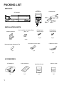
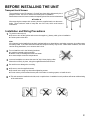
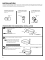
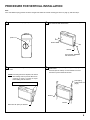
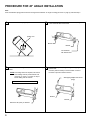
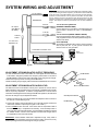
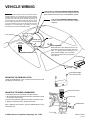
6
COMPACT
ACC-40
DIGITAL AUDIO 6 DISC
COMPACT DISC CHANGER
MODEL ACC-40
6-DISC CD CHANGER
WITH WIRED COMMANDER
COMPACT
DIGITAL AUDIO
INSTALLATION MANUAL
PACKING LIST
MAIN UNIT
Wired
Commander
CD Changer
FM Modulator
6
COMPACT
ACC-40
DIGITAL AUDIO 6 DISC
COMPACT DISC CHANGER
INSTALLATION PARTS
Mounting Bracket
Hex Head Bolt with Washer Base
(M5 x 12)
2 pcs.
4 pcs.
Phillips Head
Screw (Large)
Phillips Head
Screw (Small)
4 pcs.
2 pcs.
Mounting Angle Adjustment Tool
Screw Hole Cover Labels
1 pc.
1 pc.
5 Meter Din Cable
1 pc.
ACCESSORIES
1
CD Magazine
Index seal sheet
Installation Manual
Owner's guide
1 pc.
1 pc.
1 pc.
1 pc.
BEFORE INSTALLING THE UNIT
Transport Lock Screws
The mechanism in the CD changer is "locked" into place during shipment by the 4
transport screws. Be sure to remove the screws prior to installation.
Retain these screws for future use when transporting the unit for service/maintenance.
l Caution l
After removing the transport lock screws, place the supplied seals over the screw
holes. These seals are used to keep dust out of the unit, which could cause a
malfunction.
Installation and Wiring Precautions
1
To prevent a short-circuit,
l Be sure to turn off the ignition and remove the negative (-) battery cable, prior to installation.
l Connect power wires last.
Note
If the changer is to be installed in a car that is equipped with an on-board drive or navigation computer, do not disconnect
the battery cable. If the cable is disconnected, the computer memory may be lost. Under these conditions, use extra
caution during installation, not to cause a short circuit.
2
Do not install the unit in the following locations.
l Locations exposed to direct sunlight.
l Where hot air is discharged from the car heater.
l In areas subject to extreme temperatures.
3
Incorrect installation can cause the sound to "skip" when playing a disc.
Mount the unit firmly in place, using the supplied brackets and screws.
4
5
Be careful not to damage the car wiring.
6
l This unit cannot be installed on its side, end, or upside down. Installation in such positions will cause malfunctioning
of the mechanism.
l Be sure to use the supplied screws.
l Be careful not to snag any wires when tightening screws.
l Do not use any of the screws that are part of the brake or steering system, to install the unit.
2
INSTALLATION
The unit can be installed horizontally, vertically or at a 45° angle. The position of the built-in anti-vibration springs (left and right side), must
correspond to the mounting position chosen. If the springs are not set correctly for the type of installation chosen, the anti-vibration
compensation will not be effective and vibration may cause the disc to skip.
HORIZONTAL INSTALLATION
Set the anti-vibration springs to
position "H".
position "H"
45° ANGLE INSTALLATION
Set the anti-vibration springs to
position "45°".
position "45°"
position "V"
H
H
H
°
45
V
45°
V
45°
V
VERTICAL INSTALLAITON
Set the anti-vibration springs to
position "V".
45°
PROCEDURE FOR HORIZONTAL INSTALLATION
1
Attach a mounting bracket to each side of the unit, using the
4 hex head bolts with washer base.
45°
V
H
Bracket
NOTE: Make sure anti-vibration springs
are set to position "H".
Bracket
2
Hex head bolt
with washer base
Determine the mounting location, and drill four mounting
holes.
NOTE: If mounting surface is carpeted, use caution
when drilling holes to prevent drill bit from
catching on carpet. Cut holes in carpet
before drilling into sub-surface.
Drill holes 1/8" (4mm) in diameter.
Never mount the unit near the fuel tank.
3
Secure the unit in place, using four large self-tapping Phillips
head screws.
Use RTV (silicone sealer) on screw threads or around
the holes to prevent moisture intrusion.
Self-tapping Phillips head screw
(large)
Bracket
Bracket
3
PROCEDURE FOR VERTICAL INSTALLATION
Note
If the anti-vibration spring position has been changed and verified for vertical mounting (as shown on page 3), start with step 2.
1
Set the anti-vibration springs to position "V".
2
Attach a mounting bracket to each side of the unit, using the
hex head bolts with washer base.
position "V"
45°
V
Bracket
H
Bracket
Hex head bolt
with washer base
3
Determine the mounting location, and drill four mounting
holes.
4
Mount the unit in place, using four large self-tapping Phillips
head screws.
Use RTV (silicone sealer) on screw threads or around
the holes to prevent moisture intrusion.
NOTE: If mounting surface is carpeted, use caution
when drilling holes to prevent drill bit from
catching on carpet. Cut holes in carpet
before drilling into sub-surface.
Self-tapping
Phillips head screw
(large)
Never mount the unit near the fuel tank.
Bracket
Bracket
Drill holes 1/8" (4mm) in diameter
4
PROCEDURE FOR 45° ANGLE INSTALLATION
Note
If the anti-vibration spring position has been changed and verified for 45° angle mounting (as shown on page 3), start with step 2.
1
Set the anti-vibration springs to position "45°".
2
Attach a mounting bracket to each side of the unit, using the
4 hex head bolts with washer base.
position "45°"
45
V
°
Bracket
H
Bracket
Hex head bolt
with washer base
45°
3
Determine the mounting location, and drill four mounting
holes.
NOTE: If mounting surface is carpeted, use caution
when drilling holes to prevent drill bit from
catching on carpet. Cut holes in carpet
before drilling into sub-surface.
4
Mount the unit in place, using four large self-tapping Phillips
head screws.
Use RTV (silicone sealer) on screw threads or around
the holes to prevent moisture intrusion.
Self-tapping Phillips head screw
(large)
Never mount the unit near the fuel tank.
Bracket
Bracket
Drill holes 1/8" (4mm) in diameter
5
SYSTEM WIRING AND ADJUSTMENT
IMPORTANT - Some import cars use a special dual antenna “Diversity" system.
If your car has this type of antenna system, you will find the antenna cable will
not fit the socket on the FM modulator. Use of the ACC-40 with “Diversity"
systems is not recommended. You may also find some GM cars and others
have an antenna plug that is too small to mate with the socket on the FM
modulator. If this is found, call Audiovox’s Toll-Free Assistance for a special
adaptor. This adaptor can also be purchased at most car stereo installation
center.
To car antenna
FM Modulator
Fuse 2A
RF output
(89.1MHz or
88.7MHz)
Fuse 5A
+12 volt Accessory/Switched
(ORANGE w/WHITE STRIPE)
Connect this wire to a point which is energized when the
ignition switch is turned to the "ON" or "ACCESSORY"
position.
+12 volt Constant (GREEN w/WHITE STRIPE)
Connect this lead to the cable to which power is continuously supplied and which has been passed through the
vehicle's fuse block.
Antenna
socket
To +12V ACC,
Speakers, etc.
Ground (BLACK)
Screw this to a metal part of the vehicle. Clean connecting
area of paint, dirt, etc. A poor ground connection can
cause incorrect or noisy operation.
Commander connection cord
Wired
Commander
6
COMPACT
O
P
E
N
MUT
LOU
T/F
1
2
3
4
5
6
FM Radio
EQ
TAPE
AS/PS
BAND
ACC-40
DIGITAL AUDIO 6 DISC
COMPACT DISC CHANGER
MAN
SEK
DIN cable
CD changer
ADJUSTMENT OF FM MODULATOR OUTPUT FREQUENCY
FM Modulator
If there is interference from a local station or a clear signal cannot be obtained
on 89.1 MHz., change the position of the frequency select switch on the side of
the FM Modulator and tune the radio to 88.7 MHz. when using the CD changer.
l Select the frequency before mounting the FM Modulator.
l Radio sensitivity may be slightly reduced when the FM Modulator is connected.
l
Slide Switch
ADJUSTMENT OF FM MODULATOR AUDIO LEVEL
Move to 88.7M Position
The audio level from the modulator is factory-set to provide the correct volume
balance between radio and CD changer in the majority of installations and usually
will not require any adjustment. If, however, a large difference in volume level is
noted when switching between CD changer and FM radio operation, the audio level
from the CD changer may be adjusted as follows:
#0 Phillips Screwdriver
1. With the CD changer off, tune to an FM station and adjust the volume control on
the radio to a normal listening level.
FM Modulator
2. Leaving the volume control at the setting, turn on the CD changer and tune the
radio to the modulator output frequency (89.1 or 88.7 MHz.).
3. Select a LOUD section of the CD. If the volume level is comparable to that of
the FM station in step 1, no adjustment is necessary. If it is noticeably louder or
more quiet than that of the radio station, use a # 0 Phillips screwdriver to adjust
the "AUDIO LEVEL" control on the modulator so that the CD changer volume
is comparable to that of the radio station.
dio
Au
l
ve
Le
Ad
jus
t
IMPORTANT: If the modulator audio level is adjusted too high, it may result in
unacceptable levels of distortion during loud sections of CD's. If set too low, it may
result in poor signal/noise levels during CD changer operation.
6
VEHICLE WIRING
IMPORTANT - Some import cars use a special dual antenna
“Diversity" system. If your car has this type of antenna system,
you will find the antenna cable will not fit the socket on the FM
modulator. Use of the ACC-40 with “Diversity" systems is not
recommended. You may also find some GM cars and others
have an antenna plug that is too small to mate with the socket
on the FM modulator. If this is found, call Audiovox’s Toll-Free
Assistance for a special adaptor. This adaptor can also be
purchased at most car stereo installation center.
From antenna
+12V Accessory / Switched (ORANGE w/WHITE STRIPE)
Connect this wire to a terminal which is energized when the
ignition switch is turned to the "ON" or "ACCESSORY" position.
+12V Constant (GREEN w/WHITE STRIPE)
Connect this wire to a terminal which is always
energized.
To FM radio antenna
input
Fuses
FM radio
Wired
Commander
FM modulator
Commander connection cord
Ground (BLACK)
Attach this wire to the chassis of the car. Be
sure that the surface is free of paint, and is not
rusty. If a proper ground connection is not
made, the CD changer may not operate
correctly and stray noise may be picked
up by the unit.
CD changer
DIN cable
Self-tapping Phillips
head screw (small)
MOUNTING THE FM MODULATOR
Install the FM Modulator to the mounting surface with the small
self-tapping screws (M3 x 12).
Wired Commander
MOUNTING THE WIRED COMMANDER
1. Determine where the commander unit will be located.
2. Be sure that the mounting surface where the commander unit will
be located is clean and dry.
3. Remove the protective paper from the back of the Velcro strip.
4. Apply the commander unit to the desired location.
After completing all connections, press the RESET button on the
commander unit.
© 2000 Audiovox Corporation, Happauge, N.Y. 11788
Velcro Strip
FM Modulator
Printed in Korea
128-5582A