1
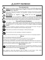
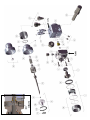
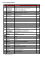
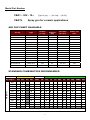
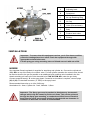
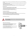
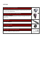
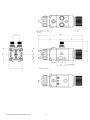
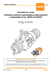
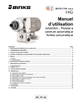
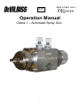
EN SB-E-2-CBA1 ISS.10 Operation Manual Cobra 1 – Automatic Spray Gun 1 Operation Manual Cobra 1 Automatic Spraygun Important Read and follow all instructions and Safety Precautions before using this equipment CHARACTERISTICS This automatic spray gun complies to ATEX regulations 94/9/EC, protection level II 2 G X, suitable to use in Zones 1 & 2. This Cobra 1 is a production spray gun suitable for use with automatic and semi-automatic machine in conventional, HVLP or Trans-Tech application. To handle a wide range of coating materials the material passages are manufactured from high grade stainless steel. Fluid tips and needles are available in high grade stainless steel. Pressure feed material supply can be re-circulating or direct. The needle adjustment knob has 18 ratchet positions, allows fine and accurate fluid flow control. SPECIFICATIONS & MATERIALS OF CONSTRUCTION Thread Fluid inlet & recirculation “P” 1/4 BSP Pressure Max 7 Bar Air inlet (Atom+Fan) 1/4 BSP Max 7 Bar 1/8 BSP 4 to 7 Bar Cylinder/trigger “A” “F” “Cyl” Maximum temperature in use 40° C Spray gun weight 720 g Gun body Aluminium hard anodized Tip / Needle / Spray head Stainless steel 303 EC Declaration of Conformity We, ITW Finishing UK, Ringwood Rd, Bournemouth, Dorset, BH11 9LH, UK, as the manufacturer of the Spray gun model COBRA , declare, under our sole responsibility that the equipment to which this document relates is in conformity with the following standards or other normative documents: BS EN 292-1 PARTS 1 & 2: 1991, BS EN 1953: 1999; and thereby conform to the protection requirements of Council Directive 98/37/EEC relating to Machinery Safety Directive, and; EN 13463-1:2001, council Directive 94/9/EC relating to Equipment and Protective Systems intended for use in Potentially Explosive Atmospheres protection level II 2 G X. B. Holt, General Manager 24th April 2007 ITW Finishing Systems and Products reserve the right to modify equipment specification without prior notice. 2 SAFETY WARNINGS Fire and explosion Solvents and coating materials can be highly flammable or combustible when sprayed. ALWAYS refer to the coating material supplier’s instructions and COSHH sheets before using this equipment. Users must comply with all local and national codes of practice and insurance company requirements governing ventilation, fire precautions, operation and house-keeping of working areas. This equipment, as supplied, is NOT suitable for use with Halogenated Hydrocarbons. Static electricity can be generated by fluid and/or air passing through hoses, by the spraying process and by cleaning non- conductive parts with cloths. To prevent ignition sources from static discharges, earth continuity must be maintained to the spray gun and other metallic equipment used. It is essential to use conductive air and/or fluid hoses. Personal Protective Equipment Toxic vapours – When sprayed, certain materials may be poisonous, create irritation or are otherwise harmful to health. Always read all labels, safety data sheets and follow any recommendations for the material before spraying. If in doubt, contact your material supplier. The use of respiratory protective equipment is recommended at all times. The type of equipment must be compatible with the material being sprayed. Always wear eye protection when spraying or cleaning the spray gun. Gloves must be worn when spraying or cleaning the equipment. Training – Personnel should be given adequate training in the safe use of spraying equipment. Misuse Never aim a spray gun at any part of the body. Never exceed the max. Recommended safe working pressure for the equipment. The fitting of non-recommended or non-original spares may create hazards. Before cleaning or maintenance, all pressure must be isolated and relieved from the equipment. The product should be cleaned using a gun-washing machine. However, this equipment should not be left inside gun-washing machines for prolonged periods of time. Noise Levels The A-weighted sound level of spray guns may exceed 85 dB (A) depending on the setup being used. Details of actual noise levels are available on request. It is recommended that ear protection is worn at all times when spraying. Operating Spray equipment using high pressures may be subject to recoil forces. Under certain circumstances, such forces could result in repetitive strain injury to the operator. 3 4 LIST OF SPARE PARTS Rep 1 Ref SP-100-xxx-K Description Air cap and its retaining ring with seals. See chart 2 SP-200S-xx-K SP-247S-xx-K SP-259S-xx-K Tip with air separator seal Ø 0,85 / 1,0 / 1,2 / 1,4 / 1,6 /1,8 / 2,0 / 2,2 Ø 2,2 / 2,8 for Air cap 470 Ø 0,5 / 0,7 / 1,0 for Air cap 590 1 5 SPA-27-K5 Separator Kit of 5 1 6 S-14192-K4 Screw M4 x 25 kit of 4 (Torx 20 ) 4 8 Spray head Packing -Kit of 1 Packing -Kit of 10 Spacer 1 10 SPA-40 SPA-86-K SPA-86-K10 SPA-10 11 SPA-53-K10 Gasket kit of 10 2 12 SPA-1-CBA1 Gun body 1 13 AGG-403 Air valve (Fan and atomising) 2 14 S-28220X-K2 O Ring Kit of 2 1 15 SPA-6X-K Piston + Seals (16,14,15a,15b) 1 15a S-28225X-K2 O Ring Kit of 2 1 15b SPA-6-CER-K Piston 1 16 S-28219X-K4 O Ring Kit of 4 1 17 SPA-13 Piston Spring Stainless steel needle 0.5/0.7/0,85/1,0/1,2/1,4/1,6/1.8/2.0/2.2 Acetal Tipped Stainless Steel Needle 085-10 & 1,4 1 9 18 19 SPA-310-xx-K SPA-310P-xx-K SPA-310N-xx-K SPA-3 Qty 1 1 1 1 Hardened Needle 1,0 / 1,2 /1,4 / 1,6 Housing 1 20 21 22 SPA-KK-1 Ring and ball for ratchet SPA-31 Spring 1 3 1 23 SPA-37 Collar 1 24 SPA-49 Button 1 25 SPA-4 Adjusting knob 1 26* SPA-7-K Kit rear housing without adjustment 27* SPA-22-K2 Kit of air connector for remote control 28* AGGS-33 Mounting Bar 29* SS-659-CD Nut 30 S-18226 Plug ¼ BSP (No recirculation) 1 31 S-1444-H M5 Set screw, 8 long 2 32 SPA-26 Plug (No recirculation) 1 33 ADV-403-K Retaining ring & seals 1 34* SPA-112 Index ring (Air cap) 1 35 SPA-20V-K5 Packing & O Ring kit of 5 (CBA1V) 1 *Optional spare parts 5 Model Part Number CBA1 – 522 - 12 = CBA1V [Type of gun] – [Air Cap] – [Ø Tip] Spray gun for ceramic applications AIR CAP CHART AVAILABLE Air cap SP-100-430-K SP-100-443-K SP-100-470-K SP-100-497-K SP-100-500R-K SP-100-505-K SP-100-510-K SP-100-513-K SP-100-515-K SP-100-522-K SP-100-523-K SP-100-590-K SP-100-590HV-K SP-100-591-K SP-100-520-K Type Air Flow (L / min) Conventional Conventional Conventional Conventional HVLP HVLP Trans-Tech Trans-Tech Trans-Tech Trans-Tech Trans-Tech Trans-Tech Trans-Tech Trans-Tech Trans-Tech 340 345 465 510 195 385 283 531 385 410 410 218 310 218 283 At Inlet Pressure (bar) 3,5 3,0 3,0 3,5 1,0 1,4 2,0 3,0 2.0 2,0 2,0 2,0 2.0 2,0 2.0 Fluid Flow (ml / min) Pattern size (mm) 200 - 280 200 - 300 500 - 1800 200 - 600 130 –190 130 –190 160 - 220 200 - 600 200 - 400 200 - 600 200 - 400 50 -150 50 - 150 50 -150 150 - 250 200 300 420 380 round 270 270 350 320 350 150 150 120 150 280 STANDARD COMBINATION RECOMMENDED Air Cap N° 430 443 470 497 TIP Ø mm Conventional 0,5 0,6 0,7 0,85 1,0 1,2 1,4 1,6 1,8 2,0 2,2 2,8 X X X X X X Trans-Tech HVLP Type 500R 505 510 513 515 520 522 523 590 590HV 591 X X X X X X X X X X X X X X X X X X X X X X X X X X X X X X X X X X X X X X X X X X X X X X X X X X X X X X X X X Combination « X » are available and fitted as standard. 6 A Adjusting knob B Sprayhead C Air cap Retaining Ring D Air Cap E Valve (Fan and atom) F Body P Product inlet/ outlet G Fluid tip INSTALLATION Important : To ensure that this equipment reaches you in first class condition, protective coatings have been used. Flush the equipment through with appropriate solvent before use. Fix the spray gun using mounting stem ref.28 and secure it with nut ref.29. HOSES Use separate filtered regulated air supplies for atomizing and cylinder air. Connect the cylinder air ‘CYL AIR’ on top of the body via a control valve. For fast cylinder operation the control valve should be fitted as close to the gun as possible or an additional quick exhaust valve installed in the line. Attach atomizing air hose to the inlet threaded hole ‘FAN & ATOM AIR’ under the gun body. Connect material hose(s) ‘P’ to the spray head. If material re-circulation is required, remove plugs (30) & (32). Fit standard connector (¼” BSP) to the spray head. Recommended hose size up to 10m (34ft) long : Atomization Air : 8mm, Cylinder Air : 6mm, Material : 9,5mm Important : The Spray gun must be earthed to dissipate any electrostatic charges which may be created by fluid or air flows. This can be achieved through the Spray gun mounting, or conductive air/fluid hoses. Electrical bond from the spray gun to earth should be checked with an ohmmeter. A resistance of less than 106 Ohms is recommended. 7 SETTING 1. The ATOM air valve controls the atomizing air pressure FAN valve reduces the spray pattern size. To increase the pressure turn clockwise, to reduce turn counter-clockwise. 2. Fluid flow can be adjusted with the rear ratchet knob, fluid flow is increased when you turn the knob counter-clockwise. 3. For the arrangement of the parts, refer the exploded view at the end of the manual. STARTING UP 1. Turn the needle adjusting knob (25) clockwise until the needle is fully closed. 2. Turn the FAN and ATOM air valves (13) counter-clockwise to be full open. 3. Use the air cap chart above to set the air pressure at the air regulator to achieve recommended pressures above. 4. Turn the adjusting knob (25) counter clockwise to obtain the desired fluid flow. 5. Test spray. If the finish is too dry or fine, reduce the airflow by reducing the air inlet pressure or by screwing the valve ATOM (13) in clockwise, or increase the fluid flow using ratchet knob, rotating counter clockwise. 6. If the finish is too wet, turn the ratchet knob (25) in clockwise to reduce the fluid flow, or reduce the fluid pressure. If the atomization is too coarse, increase inlet air pressure, or reduce fluid flow. 7. The pattern size can be reduced by turning adjusting valve FAN (13) clockwise. 8. The spray pattern will give the best results when perpendicular to the target. 9. The recommended spray distance is 150-220 mm (6’’ to 8’’). 10. Spray edges first. Overlap each stroke a minimum of 50%. Move gun at a constant speed. 11. Always turn off air and fluid supply and relieve pressure and clean down when gun is not in us. PREVENTIVE MAINTENANCE 1. Turn off air and coating supply and relieve pressure in the supply lines, or disconnect from airline and fluid line. 2. Remove air cap (1) and clean. If any of the holes in the cap are blocked with coating material use a toothpick to clean. Never use metal wire which could damage the cap and produce distorted spray patterns 3. Ensure the nozzle of the fluid tip (2) is clean and free from damage. Any build up of dried paint can distort the spray pattern. REPLACEMENT OF PARTS Turn off air and coating supply and relieve pressure in the supply lines, before any maintenance operation. Tip (2) & needle (18) Remove the air cap (1) by unscrewing its retaining ring counter- clockwise. Remove the tip (2) and its air separator ring (3) by unscrewing by unscrewing counter- clockwise with 10mm hexagonal spanner. Unscrew the adjusting needle knob (25) fully in counter-clockwise rotation, push the needle from the 8 front of the spay gun, carefully so to avoid damage the needle end, then pull out the needle (18) from the back. If necessary, replace the needle and the tip, first screw the tip with its air separator ring (recommended torque between 9,5 to 12 Nm). Lubricate all the surface of the needle which will be in contact with the packing and O ring. Slide the needle into the spray gun from the back. Fit the needle springs with its plastic pad (22,23,24) and screw the needle adjusting knob (25). Packing seal (9) Unscrew the air cap (1), tip (2) and its air separator ring (3). Unscrew the 4 screws (6) to disassemble the gun head (8). Push back the packing seal (9) using a rod diameter 5,5mm from the front of the gun head. Clean the packing location hole carefully with adequate solvent. Fit a new packing seal (9) U face towards the fluid passage. Packing seal (35) CBA1V Unscrew the air cap (1), tip (2) and its air separator ring (3). Unscrew the 4 screws (6) to disassemble the gun head (8). Push back the packing seal and O ring (35) using a rod diameter 5,5mm from the front of the gun head. Clean the packing location hole carefully with adequate solvent. Fit a new O ring and packing seal (35) U face towards the fluid passage. Fan & Atom air valve (13) Before assembling, check the air valve is in fully open position by unscrewing it counter-clockwise. Piston (15), O ring (16) & (14) Unscrew the rear housing (19) at the back of the gun body counter clockwise, pull out the needle (18). Use bent nose pliers so to pull out the piston which has a 12mm internal groove for this purpose. It’s recommended to replace the o ring (14) into the gun body as soon you disassemble the Piston. If necessary, when replacing the piston, slightly lubricate the piston lip before fitting into the gun body. 9 OPTIONS Spray gun without needle adjustment Part number: SPA-7-K This kit includes the back piece and washer to replace the part items 19, 20, 21, 24, 25, on the exploded view. Spray gun with “Atom” & “fan” remote control Parts number: SPA-22-K2 This includes 2 connectors taking place of the two 2 air valves (13) on the exploded view. Spray gun shaft Part number: AGGS-33 Nut for spray gun shaft Part number: SS-659-CD Ring to index air cap with spray gun head Part number : SPA-112 : Indexed ring 0 & 90° © 2011 ITW Finishing Systems and Products 11 ITW Finishing Systems and Products Ringwood Road, Bournemouth, BH11 9LH, England. Tel. No. (01202) 571111 Telefax No. (01202) 581940, Website address http://www.itweuropeanfinishing.com ITW Finishing Systems and Products is a Division of ITW Ltd. Reg. Office: Admiral House, St Leonard’s Road, Windsor, Berkshire, SL4 3BL, UK Registered in England: No 559693 Vat No 619 5461 24 12 © 2011 ITW Finishing Systems and Products