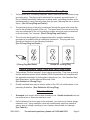
1
10” COMPOUND SLIDE MITER SAW
Model 90891
Set up And Operating Instructions
Diagrams within this manual may not be drawn proportionally.
Due to continuing improvements, actual product may differ slightly from the product described herein.
Distributed exclusively by Harbor Freight Tools®.
3491 Mission Oaks Blvd., Camarillo, CA 93011
Visit our website at: http://www.harborfreight.com
Read this material before using this product.
Failure to do so can result in serious injury.
Save this manual.
Copyright© 2003 by Harbor Freight Tools®. All rights reserved. No portion of this
manual or any artwork contained herein may be reproduced in any shape or form
without the express written consent of Harbor Freight Tools.
For technical questions or replacement parts, please call 1-800-444-3353.
Cover revised 07h
SPECIFICATIONS
Electrical
Requirements
Arbor Diameter
Positive Stops
Blade Diameter
Cutting Capacity
Features
Accessories
120 V / 60 Hz / 4600 RPM
10.8 A Input Working Amperage (with load)
1-3/4 HP Motor / Single Phase
2-Prong Power Plug
Double Insulated Motor w/ External Access Brushes
5/8” (0.625”)
0°, 15°, 22.5°, 30°, 45° Miter
0°, 45° Compound
10”, 60 Tooth, C2 Carbide Tipped Blade
At 90 Degrees: 3-1/2” Deep x 12” Front to Back
At 45 Degrees: 1-3/4” Deep x 10” Front to Back
Trigger Safety Button
Transparent, Retractable, Blade Guard
Workpiece Holders (Qty. 2)
Hex Socket Wrench (Qty. 1)
Baffle Plate (Qty. 1)
Baffle Plate Screw (Qty. 1)
Carbon Brushes (Qty. 2)
Dust Collect Bag (Qty. 1)
E105017
SAVE THIS MANUAL
You will need this manual for the safety warnings and precautions, assembly,
operating, inspection, maintenance and cleaning procedures, parts list and assembly
diagram. Keep your invoice with this manual. Write the invoice number on the inside
of the front cover. Keep this manual and invoice in a safe and dry place for future reference.
GENERAL SAFETY RULES
WARNING! Read all instructions
Failure to follow all instructions listed below may result in electric shock,
fire, and/or serious injury. The term “power tool” in all of the warnings listed
below refers to your mains-operated (corded) power tool or battery-operated
(cordless) power tool.
SAVE THESE INSTRUCTIONS
WORK AREA
1.
Keep your work area clean and well lit. Cluttered benches and dark areas
invite accidents.
REV 05i, 07h
SKU 90891
For technical questions, please call 1-800-444-3353.
Page 2.
Do not operate power tools in explosive atmospheres, such as in the presence of flammable liquids, gases, or dust. Power tools create sparks which
may ignite the dust or fumes.
3.
Keep bystanders, children, and visitors away while operating a power tool.
4.
Distractions can cause you to lose control. Protect others in the work area from
debris such as chips and sparks. Provide barriers or shields as needed.
ELECTRICAL SAFETY
1.
Grounded tools must be plugged into an outlet properly installed and
grounded in accordance with all codes and ordinances. Never remove the
grounding prong or modify the plug in any way. Do not use any adapter
plugs. Check with a qualified electrician if you are in doubt as to whether
the outlet is properly grounded. If the tools should electrically malfunction or
break down, grounding provides a low resistance path to carry electricity away
from the user.
2.
Double insulated tools are equipped with a polarized plug (one blade is
wider than the other). This plug will fit in a polarized outlet only one way.
If the plug does not fit fully in the outlet, reverse the plug. If it still does
not fit, contact a qualified electrician to install a polarized outlet. Do not
change the plug in any way. Double insulation eliminates the need for the
three wire grounded power cord and grounded power supply system.
3.
Avoid body contact with grounded surfaces such as pipes, radiators, ranges, and refrigerators. There is an increased risk of electric shock if your body is
grounded.
4.
Do not expose power tools to rain or wet conditions. Water entering a power
tool will increase the risk of electric shock.
5.
Do not abuse the Power Cord. Never use the Power Cord to carry the tools
or pull the Plug from an outlet. Keep the Power Cord away from heat, oil,
sharp edges, or moving parts. Replace damaged Power Cords immediately. Damaged Power Cords increase the risk of electric shock.
6.
When operating a power tool outside, use an outdoor extension cord
marked “W-A” or “W”. These extension cords are rated for outdoor use, and
reduce the risk of electric shock.
PERSONAL SAFETY
1.
Stay alert. Watch what you are doing, and use common sense when operating a power tool. Do not use a power tool while tired or under the influence of drugs, alcohol, or medication. A moment of inattention while operating
power tools may result in serious personal injury.
SKU 90891
For technical questions, please call 1-800-444-3353.
Page 2.
Dress properly. Do not wear loose clothing or jewelry. Contain long
hair. Keep your hair, clothing, and gloves away from moving parts. Loose
clothes, jewelry, or long hair can be caught in moving parts.
3.
Avoid accidental starting. Be sure the Power Switch is off before plugging
in. Carrying power tools with your finger on the Power Switch, or plugging in
power tools with the Power Switch on, invites accidents.
4.
Remove adjusting keys or wrenches before turning the power tool on. A
wrench or a key that is left attached to a rotating part of the power tool may result
in personal injury.
5.
Do not overreach. Keep proper footing and balance at all times. Proper
footing and balance enables better control of the power tool in unexpected situations.
6.
Use safety equipment. Always wear eye protection. Dust mask, non-skid
safety shoes, hard hat, or hearing protection must be used for appropriate conditions.
TOOL USE AND CARE
1.
Use clamps (not included) or other practical ways to secure and support
the workpiece to a stable platform. Holding the work by hand or against your
body is unstable and may lead to loss of control.
2.
Do not force the tool. Use the correct tool for your application. The correct
tool will do the job better and safer at the rate for which it is designed.
3.
Do not use the power tool if the Power Switch does not turn it on or off.
Any tool that cannot be controlled with the Power Switch is dangerous and must
be replaced.
4.
Disconnect the Power Cord Plug from the power source before making any
adjustments, changing accessories, or storing the tool. Such preventive
safety measures reduce the risk of starting the tool accidentally.
5.
Store idle tools out of reach of children and other untrained persons. Tools
are dangerous in the hands of untrained users.
6.
Maintain tools with care. Keep cutting tools sharp and clean. Properly
maintained tools with a sharp cutting edge are less likely to bind and are easier
to control. Do not use a damaged tool. Tag damaged tools “Do not use” until
repaired.
.
Check for misalignment or binding of moving parts, breakage of parts, and
any other condition that may affect the tool’s operation. If damaged, have
the tool serviced before using. Many accidents are caused by poorly maintained tools.
SKU 90891
For technical questions, please call 1-800-444-3353.
Page 8.
Use only accessories that are recommended by the manufacturer for your
model. Accessories that may be suitable for one tool may become hazardous
when used on another tool.
SERVICE
1.
Tool service must be performed only by qualified repair personnel. Service
or maintenance performed by unqualified personnel could result in a risk of injury.
2.
When servicing a tool, use only identical replacement parts. Follow instructions in the “Inspection, Maintenance, And Cleaning” section of this
manual. Use of unauthorized parts or failure to follow maintenance instructions
may create a risk of electric shock or injury.
SPECIFIC SAFETY RULES
1.
Maintain a safe working environment. Keep the work area well lit. Make sure
there is adequate surrounding workspace. Always keep the work area free of
obstructions, grease, oil, trash, and other debris. Do not use the Miter Saw in
areas near flammable chemicals, dusts, and vapors. Do not use this product in a
damp or wet location.
2.
Maintain labels and nameplates on the Miter Saw. These carry important
information. If unreadable or missing, contact Harbor Freight Tools for a replacement.
3.
Do not force the equipment. This Miter Saw will do the work better and safer at
the speed and capacity for which it was designed.
4.
Keep all guards in place and in working order.
5.
Remove all adjusting wrenches from the Miter Saw before turning it on.
6.
Do not abuse the Power Cord. Do not use the Power Cord to pull its Plug from
an electrical outlet. Keep the Power Cord away from heat, oil, sharp edges, and
moving parts. Route the Power Cord safely. Protect the Power Cord from being damaged by other equipment in the work area. Do not route the Power Cord
where it can be walked on or tripped over. Replace a damaged Power Cord immediately.
.
Make sure the Power Switch is in the “OFF” position before plugging in the
Power Cord.
8.
Do not use this Miter Saw for cutting metals or brittle materials. Do not cut
dangerous materials, such as asbestos which can cause harmful dust or vapors.
SKU 90891
For technical questions, please call 1-800-444-3353.
Page 9.
When replacing the Saw Blade, make sure the new Saw Blade has a diameter of 10”, has an RPM rating of at least 4600, and has an arbor hole of 5/8”
diameter.
10.
To avoid accidental injury, always wear heavy duty work gloves when
changing a Saw Blade.
11.
Before using the Miter Saw, make sure the Saw Blade is properly mounted
on the Saw Spindle. Make sure the Saw Blade is balanced, and is not cracked
or bent.
12.
The Saw Blade will become hot while cutting. Allow the Saw Blade to completely cool before touching.
13.
Allow the Saw Blade to spin up to full speed before feeding it into wood.
When turning off the Miter Saw, allow the Saw Blade to spin down and stop on its
own. Do not press against the Saw Blade to stop it.
14.
Do not force the material into the Saw Blade when cutting. Apply moderate
pressure, allowing the Saw Blade to cut without being forced.
15.
Never attempt to remove material stuck in the moving parts of the Miter
Saw while the machine is plugged in and running.
16.
Whenever possible, use clamps or other safe, practical ways to hold and
support the workpiece. Do not attempt to cut material that does not have a flat
surface, unless a suitable support is used.
1.
Turn off the Miter Saw and allow the Saw Blade to stop on its own if the
Saw Blade is to be backed out of an uncompleted cut.
18.
Always keep hands and fingers away from the spinning Saw Blade.
19.
Use eye, hearing, and breathing protection. Always wear ANSI approved
safety impact eye goggles, hearing protectors, and dust masks or respirator
when working with the Miter Saw.
20.
Do not use this product if under the influence of alcohol or drugs. Read warning
labels on prescriptions to determine if your judgement or reflexes are impaired
while taking drugs. If there is any doubt, do not attempt to use this product.
21.
Industrial applications must follow OSHA requirements.
22.
Maintain this product with care. Keep the Miter Saw clean and dry for better and
safer performance. For your safety, service and maintenance should be performed regularly by a qualified technician.
23.
Use the right tool or attachment for the right job. Do not attempt to force a
small tool or attachment to do the work of a larger industrial tool or attachment.
There are certain applications for which this product was designed. It will do the
SKU 90891
For technical questions, please call 1-800-444-3353.
Page job better and more safely at the rate for which it was intended. Do not modify
this product, and do not use this product for a purpose for which it was not intended.
24.
Always turn off the Miter Saw and unplug the Power Cord from its electrical
outlet before changing accessories or performing any inspection, maintenance, or cleaning procedures.
25.
WARNING: Some dust created by power sanding, sawing, grinding, drilling, and
other construction activities, contains chemicals known [to the State of California]
to cause cancer, birth defects or other reproductive harm. Some examples of
these chemicals are:
Lead from lead-based paints
Crystalline silica from bricks and cement or other masonry products
Arsenic and chromium from chemically treated lumber
Your risk from these exposures varies, depending on how often you do this type
of work. To reduce your exposure to these chemicals: work in a well ventilated
area, and work with approved safety equipment, such as those dust masks that
are specially designed to filter out microscopic particles. (California Health &
Safety Code § 25249.5, et seq.)
26.
People with pacemakers should consult their physician(s) before use. Electromagnetic fields in close proximity to heart pacemaker could cause pacemaker
interference or pacemaker failure.
2.
The warnings, precautions, and instructions discussed in this manual cannot
cover all possible conditions and situations that may occur. The operator must
understand that common sense and caution are factors which cannot be built into
this product, but must be supplied by the operator.
28.
Only lock the Motor Housing in the lock down position for carrying or storing the
Miter Saw. Never attempt to cut with the Miter Saw when the Motor Housing is in
the lock down position.
Grounding
WARNING
Improperly connecting the grounding wire can result in
electric shock.
Check with a qualified electrician if you are in doubt as to
whether the outlet is properly grounded. Do not modify
the power cord plug provided with the tool. Never remove
the grounding prong from the plug. Do not use the tool if
the power cord or plug is damaged. If damaged, have it
repaired by a service facility before use. If the plug will not
fit the outlet, have a proper outlet installed by a qualified
electrician.
SKU 90891
For technical questions, please call 1-800-444-3353.
Page Grounded Tools: Tools with Three Prong Plugs
1.
Tools marked with “Grounding Required” have a three wire cord and three prong
grounding plug. The plug must be connected to a properly grounded outlet. If
the tool should electrically malfunction or break down, grounding provides a low
resistance path to carry electricity away from the user, reducing the risk of electric
shock. (See 3-Prong Plug and Outlet.)
2.
The grounding prong in the plug is connected through the green wire inside the
cord to the grounding system in the tool. The green wire in the cord must be the
only wire connected to the tool’s grounding system and must never be attached
to an electrically “live” terminal. (See 3-Prong Plug and Outlet.)
3.
The tool must be plugged into an appropriate outlet, properly installed and
grounded in accordance with all codes and ordinances. The plug and outlet
should look like those in the following illustration.
(See 3-Prong Plug and Outlet.)
3-Prong Plug and Outlet
Outlets for 2-Prong Plug
Double Insulated Tools: Tools with Two Prong Plugs
1.
Tools marked “Double Insulated” do not require grounding. They have a special
double insulation system which satisfies OSHA requirements and complies with
the applicable standards of Underwriters Laboratories, Inc., the Canadian Standard Association, and the National Electrical Code.
(See Outlets for 2-Prong Plug.)
2.
Double insulated tools may be used in either of the 120 volt outlets shown in the
preceding illustration. (See Outlets for 2-Prong Plug.)
Extension Cords
1.
Grounded tools require a three wire extension cord. Double Insulated tools can
use either a two or three wire extension cord.
2.
As the distance from the supply outlet increases, you must use a heavier gauge
extension cord. Using extension cords with inadequately sized wire causes a
serious drop in voltage, resulting in loss of power and possible tool damage.
(See Table A.)
SKU 90891
For technical questions, please call 1-800-444-3353.
Page 3.
The smaller the gauge number of the wire, the greater the capacity of the cord.
For example, a 14 gauge cord can carry a higher current than a 16 gauge cord.
(See Table A.)
4.
When using more than one extension cord to make up the total length, make
sure each cord contains at least the minimum wire size required. (See Table A.)
5.
If you are using one extension cord for more than one tool, add the nameplate
amperes and use the sum to determine the required minimum cord size.
(See Table A.)
6.
If you are using an extension cord outdoors, make sure it is marked with the suffix “W-A” (“W” in Canada) to indicate it is acceptable for outdoor use.
.
Make sure the extension cord is properly wired and in good electrical condition.
Always replace a damaged extension cord or have it repaired by a qualified electrician before using it.
8.
Protect the extension cords from sharp objects, excessive heat, and damp or wet
areas.
RECOMMENDED MINIMUM WIRE GAUGE FOR EXTENSION CORDS* (120/240 VOLT)
NAMEPLATE
AMPERES
EXTENSION CORD LENGTH
(at full load)
25 Feet
50 Feet
75 Feet
100 Feet
150 Feet
0 – 2.0
18
18
18
18
16
2.1 – 3.4
18
18
18
16
14
3.5 – 5.0
18
18
16
14
12
5.1 – 7.0
18
16
14
12
12
7.1 – 12.0
18
14
12
10
-
12.1 – 16.0
14
12
10
-
-
16.1 – 20.0
12
10
-
-
-
TABLE A
* Based on limiting the line voltage drop to five volts at 150% of the rated amperes.
Symbology
Double Insulated
Canadian Standards Association
Underwriters Laboratories, Inc.
SKU 90891
V~
A
Volts Alternating Current
Amperes
No Load Revolutions per Minute
n0 xxxx/min. (RPM)
For technical questions, please call 1-800-444-3353.
Page UNPACKING
When unpacking, check to make sure all the parts shown on the Parts Lists on
pages 22 and 23 are included. If any parts are missing or broken, please call Harbor
Freight Tools at the number shown on the cover of this manual as soon as possible.
ASSEMBLY AND Functions
Note: For additional references to the parts listed in the following pages, refer to the Assembly Diagrams on pages 24 and 25.
To Assemble The Accessories:
WARNING! Prior to performing any assembly procedures, make sure the Power
Cord of the Miter Saw is unplugged from its electrical outlet.
1.
The Miter Saw comes with several accessories that may be attached to the unit.
ELBOW
(47)
FIGURE D
2.
DUST COLLECTION BAG
(154)
BAFFLE PLATE
(151)
HOLDER (149)
The Dust Collection Bag (154) can be attached by inserting the bag opening onto the top of the Elbow (47). The Dust Collection Bag helps keep the work area clean by catching sawdust and wood chips which are thrown off by the Saw Blade (51). When the Dust Collection Bag is half full, remove it from the Miter Saw, empty, and reattach it to the Miter Saw. (See Figure D.)
SKU 90891
For technical questions, please call 1-800-444-3353.
Page 10
ADJUSTING KNOB (102)
WING SCREW (97)
GUIDE FENCE (105)
BAFFLE PLATE (151)
FIGURE E
WING SCREW (148)
HOLDER (149)
3.
A workpiece Clamp Assembly (95, 96, 97, 98, 99, 100, 101, 102) can be installed
by inserting the Assembly into the hole located in the Guide Fence (105). Once
inserted, lock the Assembly in place with a Wing Screw (97). To clamp the workpiece to the Base (147) of the Miter Saw, turn the Adjusting Knob (102) clockwise. (See Figure E.)
4.
A workpiece Holder (149) can be inserted into each side of the Base (147), adjusted for the desired length, and locked in place with a Wing Screw (148). The
Holders should be used as supports when cutting longer length workpieces.
(See Figure E.)
5.
The Baffle Plate (151) can be attached to the workpiece Holder (149) and locked
in place with a Wing Screw (152). Once attached and locked in place, the Baffle
Plate allows you to make repeated cuts of the same length. To do so, loosen
the Wing Screw (148) that holds the Holder (149) in place. Measure the distance
from the Saw Blade (51) to the Baffle Plate and, when the desired length of cut is
determined, lock the Holder in place with the Wing Screw (148).
(See Figures D, and E.)
To Mount The Miter Saw:
1.
When in use, the Miter Saw should be securely mounted to a flat, level, sturdy
table/workbench capable of supporting the weight of the Miter Saw, accessories,
and the workpieces being cut.
2.
Located on the front side of the Miter Saw’s Base (147) are two 1/4” mounting
holes. Using the two mounting holes as a template, mark the two 1/4” holes that
are to be drilled through the table/workbench. Drill the holes and secure the Miter Saw to the table/workbench, using two 1/4” bolts, lock washers, and nuts (not
included). (See Figure F, next page.)
SKU 90891
For technical questions, please call 1-800-444-3353.
Page 11
FIGURE F
Front Cover
with Support
Leg (117)
1/4” MOUNTING HOLE
3.
1/4” MOUNTING HOLE
Use two C-clamps (not included) to secure the back side of the Miter Saw to the
table/workbench.
To Remove/Install A Saw Blade:
WARNING! Prior to performing this procedure, make sure the Miter Saw is unplugged from its electrical outlet.
When replacing a Saw Blade (51), make sure the new Saw Blade has a 10”
diameter, rated to at least 4600 RPM, made to fit a 5/8” (0.625”) Spindle, and
suited for the type of material being cut.
SAFETY COVER (58)
SAW BLADE (51)
FIGURE G
1.
Lift up and hold the transparent Safety Cover (58) in place. (See Figure G.)
SKU 90891
For technical questions, please call 1-800-444-3353.
Page 12
SAFETY COVER (58)
FLAT HEAD SCREW (60)
CENTER COVER (55)
FIGURE H
2.
Remove the Flat Head Screw (60) and Center Cover (55). (See Figure H.)
SAFETY BUTTON
(16)
SWITCH LEVER
(25)
SHAFT LOCK (1)
HANDLE COVER
(40)
SAFETY COVER (58)
FIGURE I
3.
Press in and hold the Shaft Lock (1) to keep the Spindle (35) from turning.
(See Figure I.)
4.
Use the accessory Hex Socket Wrench (150) to remove the Hex Flange Head
Bolt (61). NOTE: To remove the Hex Flange Head Bolt (61), turn the Bolt
CLOCKWISE. (See Figure J, next page.)
5.
Remove the Flange (52). (See Figure J, next page.)
SKU 90891
For technical questions, please call 1-800-444-3353.
Page 13
FLANGE (52)
HEX FLANGE HEAD BOLT (61)
HEX SOCKET WRENCH
(150)
FLANGE (52)
HEX FLANGE HEAD BOLT (61)
FIGURE J
SAW BLADE (51)
BLADE CASE (43)
ARROW
ARROW
FIGURE K
6.
Remove the old Saw Blade (51). Then mount the new Saw Blade on the Spindle
(35), making sure the arrow direction on the Saw Blade matches the arrow on the
Blade Case (43). The teeth of the Saw Blade should point toward the rear of the
Miter Saw. (See Figure K.)
SKU 90891
For technical questions, please call 1-800-444-3353.
Page 14
HEX FLANGE HEAD BOLT
(61)
SAW BLADE (51)
SPINDLE (35)
FLANGE (52)
INNER FLANGE (65)
FIGURE L
.
Insert the Flange (52) onto the Spindle (35) and against the Saw Blade (51).
NOTE: Make sure the larger diameter side of the Flange is against the Saw
Blade. (See Figure L.)
8.
Press in and hold the Shaft Lock (1) to keep the Spindle (35) from turning.
(See Figure I.)
9.
Use the accessory Hex Socket Wrench (150) to tighten the Hex Flange Head
Bolt (61) into the Spindle (35). NOTE: To tighten the Bolt turn it COUNTERCLOCKWISE. (See Figure J previous page, and L.)
10.
Replace the Center Cover (55) and Flat Head Screw (60), and allow the transparent Safety Cover (58) to return to its normal downward position. (See Figure H.)
11.
Lastly, check to make sure the Saw Blade (51) does not touch the Turn Base
(125) of the Miter Saw. (See Assy. Diagram.)
The Safety Cover For The Saw Blade:
1.
The transparent Safety Cover (58) automatically rotates to cover the Saw Blade
(51) when the Handle Cover (40) is lifted. When the Handle Cover is lowered,
the Safety Cover rotates back out of the way. (See Figure I.)
2.
Do not disconnect or remove the Safety Cover (58). Do not operate the Miter
Saw if the Safety Cover is damaged or missing. (See Figure I.)
3.
If the transparent Safety Cover (58) becomes so dirty that the Saw Blade (51)
cannot be seen clearly, disconnect the electrical Power Cord from its electrical
outlet and clean the Safety Cover with a soft, damp, cloth. A mild detergent may
be used, but do not use solvents which may damage the Safety Cover.
(See Figure I.)
SKU 90891
For technical questions, please call 1-800-444-3353.
Page 15
The Power Switch:
Note: The Miter Saw can be disabled for safety purposes by removing the Safety Button (16). Make sure to store the Safety Button in a safe place, and do not lose it.
The Miter Saw cannot be started without the Safety Button in place.
(See Figure I.)
1.
Before plugging in the Miter Saw, check the operation of the Safety Button (16)
and the Switch Lever (25). Do not operate the Miter Saw if either the Safety Button or Switch Lever are not operating properly. (See Figure I.)
2.
To operate the Miter Saw, first make sure the Motor Housing (26) is in its full up
position. NOTE: To raise and lower the Motor Housing, pull out on the Knob (74)
and move the Motor Housing fully up or fully down. Then, release the Knob to
lock the Motor Housing in position. (See Figure N, page 18.)
Note: Only lock the Motor Housing in the down position for carrying or storing the Miter
Saw. Never attempt to cut with the Miter Saw when the Motor Housing is in the
lock down position.
3.
Plug the Power Cord into the nearest 120 volt, grounded, electrical outlet. Depress the Safety Button (16) with your thumb, and squeeze the Switch Lever (25)
on the Handle Cover (40). Then, release the Safety Button. (See Figure I.)
4.
To turn off the Miter Saw, release the Switch Lever (25). This allows the Safety
Button (16) to return to the “OFF” position. (See Figure I.)
5.
Do not force the Switch Lever (25) if the Safety Button (16) is not present. This
will damage the Switch Lever mechanism. (See Figure I.)
To Adjust The Cutting Depth:
WARNING! Prior to performing this procedure, make sure the Power Cord of the
Miter Saw is unplugged from its electrical outlet.
1.
The cutting depth can be adjusted to assure that the workpiece is cut completely
through.
SKU 90891
For technical questions, please call 1-800-444-3353.
Page 16
HEX HEAD BOLT
(71)
MOTOR
HOUSING
(26)
KERF BOARD
(114)
SAW BLADE
(51)
TURN BASE
(125)
FIGURE M
2.
Push the Miter Saw’s Motor Housing (26) forward as far as it will go. Notice
whether the edge of the Saw Blade (51) passes completely through the Kerf
Board (114). (See Figure M.)
3.
If the Saw Blade (51) does not pass completely through the Kerf Board (114),
lower the Saw Blade slightly by turning the Hex Head Bolt (71) COUNTERCLOCKWISE. (See Figure M.)
4.
After adjusting the Hex Head Bolt (71), press down on the Miter Saw and make
sure the Saw Blade (51) does not contact the bottom of the Turn Base (125) or
any other part of the Saw Base. (See Figure M.)
5.
If the Saw Blade (51) touches the Turn Base (125) or any other part of the Saw
Base, turn the Hex Head Bolt (71) CLOCKWISE to raise the Saw Blade slightly
until it clears. (See Figure M.)
SKU 90891
For technical questions, please call 1-800-444-3353.
Page 17
To Adjust The Miter Angle:
WARNING! Prior to performing this procedure, make sure the Power Cord of the
Miter Saw is unplugged from its electrical outlet.
Knob (74)
FASTEN KNOB (104)
GUIDE FENCE (105)
FIGURE N
SCALE PLATE
(141)
TURN BASE
(125)
1.
The miter angle of a cut may be adjusted 0 - 45 degrees to the right or left. To do
so, loosen the Fasten Knob (104) located on the Guide Fence (105).
(See Figure N.)
2.
Move the Turn Base (125) to the right or left until the desired miter angle of cut is
indicated by the Scale Plate (141). Then, retighten the Fasten Knob (104) to lock
the Miter Saw in place. (See Figure N.)
SKU 90891
For technical questions, please call 1-800-444-3353.
Page 18
To Adjust The Support Screw:
To Adjust The Bevel Angle:
WARNING! Prior to performing this procedure, make sure the
Power Cord of the Miter Saw is unplugged from its electrical outlet.
1. The Support Screw (138) ca
adjusted by turning it clockw
lengthen it or by turning it co
clockwise to shorten it.
2. It should be adjusted so tha
just above the surface of the
bench the saw is mounted o
FIGURE O
ARM HOLDER
(82)
SCALE PLATE
(89)
LOCK HANDLE
(59)
Support Screw
(138)
1.
The bevel angle (or Saw Blade tilt capacity) may be adjusted
from 0 - 45 degrees to the left. To do so, loosen the Lock Handle (59) located at
the rear of the Miter Saw. (See Figure O.)
2.
Tilt the Arm Holder (82) until the desired compound angle of cut is achieved as
indicated on the Scale Plate (89). Then, retighten the Lock Handle (59) to lock
the Arm Holder in place. (See Figure O.)
To Adjust The Support Screw:
1.
The Support Screw (138) can be adjusted by turning it clockwise to lengthen it or
by turning it counterclockwise to shorten it.
2.
It should be adjusted so that it rests just above the surface of the table or bench
the saw is mounted on.
SKU 90891
For technical questions, please call 1-800-444-3353.
Page 19
Operation
1.
Make sure the Power Cord of the Miter Saw is unplugged from its electrical outlet. Then, if necessary, make adjustments to the workpiece Holder (149),
Baffle Plate (151), cutting depth, and miter angle and/or bevel angle.
2.
Raise the Motor Housing (26) to its full “UP” position.
3.
Check to make sure the Safety Button (16) and the Switch Lever (25) are operating properly.
4.
Place the workpiece on the Turn Base (125) and against the Guide Fence (105).
5.
Use the Clamp Assembly (95 to 102) to hold the workpiece in place.
6.
Plug the Power Cord into the nearest 120 volt, grounded, electrical outlet.
.
Depress the Safety Button (16) with your thumb, and squeeze the Switch Lever
(25) on the Handle Cover (40). Then, release the Safety Button.
8.
When the Saw Blade (51) is turning at full speed, slowly bring down the Motor
Housing (26) to complete the cut. NOTE: Feed the Saw Blade into the workpiece gradually. Do not force the machine to remove material faster than it was
designed to cut.
9.
When cutting a large workpiece, make sure its entire length is properly supported. If necessary, use a roller stand (not included) with a larger workpiece.
10.
Never attempt to remove material stuck in the moving parts of the Miter Saw
while it is plugged in and running.
11.
Turn off the Miter Saw if the workpiece is to be backed out of an uncompleted
cut.
12.
When the cut is complete, release the Switch Lever (25). This allows the Safety
Button (16) to return to the “OFF” position.
13.
Wait until the Saw Blade (51) comes to a complete stop. Then, raise the Motor
Housing (26) to its full “UP” position.
14.
Loosen the Clamp Assembly (95 to 102), and remove the workpiece and scrap
material.
15.
Unplug the Power Cord from its electrical outlet.
SKU 90891
For technical questions, please call 1-800-444-3353.
Page 20
INSPECTION, MAINTENANCE, AND CLEANING
WARNING! Always make sure the Switch Lever (25) is in its “OFF” position, and
unplug the Power Cord from its 120 volt electrical outlet before performing
any inspection, adjustments, maintenance, or cleaning.
1.
Before each use, inspect the general condition of the Miter Saw. Check for loose
screws, misalignment or binding of moving parts, cracked or broken parts, damaged electrical wiring, loose, cracked, or bent Saw Blade (51), and any other
condition that may affect its safe operation. If abnormal noise or vibration occurs,
have the problem corrected before further use.
Do not use damaged equipment.
2.
Daily: With a soft brush, cloth, or vacuum, remove all sawdust and debris from
the Miter Saw. Then, use a premium quality, lightweight machine oil to lubricate
all moving parts.
3.
When necessary: When the Dust Collection Bag (154) is half full, remove it
from the Miter Saw, empty, and re-attach it to the Miter Saw.
4.
To replace the Motor Carbon Brushes: It may become necessary at sometime
to replace the two Carbon Brushes (22) when the Motor performance decreases,
or stops working completely. The Carbon Brushes are located on each side of
the Motor Housing (26). To do so, use a standard screwdriver (not included) to
remove the two Carbon Brush Caps (21). Then, remove the two Carbon Brushes
from the Brush Holders (23). If the Carbon Brushes are worn down more than
1/2, replace both Carbon Brushes. If, however, the Carbon Brushes are just dirty
they may be cleaned by rubbing them with a pencil eraser. When installing the
Carbon Brushes, make sure the carbon portion of the Carbon Brushes contact
the Motor Armature, and that the springs face away from the Motor. Also, make
sure the springs operate freely. After cleaning or replacement, replace the Carbon Brush Caps with a screwdriver and tighten firmly.
PLEASE READ THE FOLLOWING CAREFULLY
THE MANUFACTURER AND/OR DISTRIBUTOR HAS PROVIDED THE PARTS LIST AND ASSEMBLY
DIAGRAM IN THIS MANUAL AS A REFERENCE TOOL ONLY. NEITHER THE MANUFACTURER OR
DISTRIBUTOR MAKES ANY REPRESENTATION OR WARRANTY OF ANY KIND TO THE BUYER THAT
HE OR SHE IS QUALIFIED TO MAKE ANY REPAIRS TO THE PRODUCT, OR THAT HE OR SHE IS
QUALIFIED TO REPLACE ANY PARTS OF THE PRODUCT. IN FACT, THE MANUFACTURER AND/OR
DISTRIBUTOR EXPRESSLY STATES THAT ALL REPAIRS AND PARTS REPLACEMENTS SHOULD BE
UNDERTAKEN BY CERTIFIED AND LICENSED TECHNICIANS, AND NOT BY THE BUYER. THE BUYER
ASSUMES ALL RISK AND LIABILITY ARISING OUT OF HIS OR HER REPAIRS TO THE ORIGINAL
PRODUCT OR REPLACEMENT PARTS THERETO, OR ARISING OUT OF HIS OR HER INSTALLATION
OF REPLACEMENT PARTS THERETO.
SKU 90891
For technical questions, please call 1-800-444-3353.
Page 21
PARTS LIST
Torsion Spring Assy. *
* Includes: #57 Spindle Sleeve and #58 Safety Cover. (Note: Customer must save old brass sleeve
from old Safety Cover and use it when installing new #56 Torsion Spring Assembly).
REV 05b
SKU 90891
For technical questions, please call 1-800-444-3353.
Page 22
PARTS LIST - CONTINUED
REV 04d
SKU 90891
For technical questions, please call 1-800-444-3353.
Page 23
ASSEMBLY DIAGRAM
10
1
3
2
4
5
6
8
7
35
11
15
13 14
12
16
17
18
19
20
9
21
34
32
33
31
29
44
23
27
28
36
24
25
26
30
22
43
42
41
40
39
38
37
46 45
56
55
54
53
52
51
49
50
48
61
57
58
59
83
47
62
64
63
65
66
67
68
69
70
60
71
72
73
82
81
77
80
79
76
75
74
78
Note: Some parts are listed and shown for illustration purposes only, and are not available individually as replacement parts.
SKU 90891
For technical questions, please call 1-800-444-3353.
Page 24
ASSEMBLY DIAGRAM - CONTINUED
84
85
86
87
88
89
90
138
137
136
135
134
91
92
93
94
95
96 97
99
98
100
102
101
109
110
133
103
111
112
132
104
113
105
114
131
130
154
129
106
108
107
115
116
128
127
126
125 124
117
123
122
121
120
119
118
153
152
151
150
149
148
147
146
145
144
143
142
141
Note: Some parts are listed and shown for illustration purposes only, and are not available individually as replacement parts.
REV 04d
SKU 90891
For technical questions, please call 1-800-444-3353.
Page 25