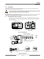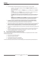
1
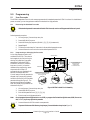
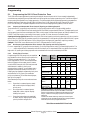
Independent Zone Control (IZC) D279A
Operation and Installation Guide
DELAYED
INSTANT
ARMED
1
2
3
4
5
6
7
8
9
*
*
D279A
D279A Operation and Installation Guide
46456E
Page 2
© 2002 Bosch Security Systems
D279A
Contents
Contents
1.0
1.1
1.2
1.3
1.3.1
1.3.2
1.4
2.0
2.1
2.2
3.0
3.1
3.2
4.0
4.1
4.2
4.3
4.4
4.5
4.6
4.7
4.8
4.9
4.10
4.11
4.12
4.13
4.14
5.0
5.1
5.1.1
5.1.2
5.2
5.2.1
5.2.2
5.2.3
5.2.4
5.3
5.3.1
5.4
5.4.1
5.5
5.5.1
5.5.2
5.6
5.6.1
5.6.2
Introduction ............................................................................................................................................................................................. 5
Manual Organization ............................................................................................................................................................ 5
Other Referenced Literature ............................................................................................................................................. 5
Documentation Conventions ............................................................................................................................................. 5
Type Styles Used in this Guide ......................................................................................................................................... 5
Tips, Notes, Cautions and Warnings ............................................................................................................................... 6
FCC Notice ............................................................................................................................................................................ 6
Overview .................................................................................................................................................................................................... 7
Specifications ........................................................................................................................................................................ 7
Features ................................................................................................................................................................................... 7
Installation ................................................................................................................................................................................................ 9
Connecting the D279A to the Panel .............................................................................................................................. 9
Connecting the D279A to the D55 Desk Stand ....................................................................................................... 10
Operation ............................................................................................................................................................................................... 11
Loop Inputs ........................................................................................................................................................................... 11
Delayed Loop ....................................................................................................................................................................... 11
Instant Loop .......................................................................................................................................................................... 11
Restorals ............................................................................................................................................................................... 11
Entry/Exit Delay ................................................................................................................................................................... 11
Arming and Disarming ........................................................................................................................................................ 11
Burglary Alarm Output ....................................................................................................................................................... 11
Panic Alarm Function ......................................................................................................................................................... 11
Relay Output ........................................................................................................................................................................ 11
Delayed LED ........................................................................................................................................................................ 11
Instant LED ........................................................................................................................................................................... 11
Armed LED ........................................................................................................................................................................... 12
Buzzer ..................................................................................................................................................................................... 12
Lit Keys .................................................................................................................................................................................. 12
Programming ....................................................................................................................................................................................... 13
User Passcode ..................................................................................................................................................................... 13
Recovering the Standard Passcode .............................................................................................................................. 13
Programming or Changing the Passcode ..................................................................................................................... 13
Programming the D8112 Panel Protective Zone ...................................................................................................... 14
Supervised Independent Zone Controls (Opening and Closing Reports) ........................................................... 14
Non-Supervised Independent Zone Controls (No Opening and Closing Reports) ........................................... 14
Priority Zone Functions ..................................................................................................................................................... 14
Audible Alarms ..................................................................................................................................................................... 15
Programming the D7112 Panel Point ............................................................................................................................ 15
Supervised Independent Zone Controls (Opening and Closing Reports) ........................................................... 15
Programming the D6112 and D4112 Panel Protective Zone ................................................................................. 15
Audible Alarms ..................................................................................................................................................................... 15
Programming the D9112B for the D279A ................................................................................................................... 15
Using the D279A to Control an Input Point ................................................................................................................ 15
Using the D279A as a Keyswitch .................................................................................................................................. 16
Programming the 9000 Series Panels for the D279A ............................................................................................. 16
Assigning the D279A to a Point with Index 17 ........................................................................................................... 16
Assigning the D279A to a Point with Index 18 ........................................................................................................... 16
D279A Operation and Installation Guide
© 2002 Bosch Security Systems
Page 3
46456E
D279A
Contents
Figures
Figure 1: Installing the D279A ........................................................................................................................................................................ 9
Figure 2: Wiring the D279A ............................................................................................................................................................................... 9
Figure 3: D279A Printed Circuit Assembly ............................................................................................................................................. 13
Tables
Table 1: D279A Independent Zone Control Operation and Installation Guide Organization ......................................... 5
Table 2: Referenced Literature ........................................................................................................................................................................ 5
Table 3: Recommended D8112 Zone Codes ......................................................................................................................................... 14
D279A Operation and Installation Guide
46456E
Page 4
© 2002 Bosch Security Systems
D279A
Introduction
1.0
Introduction
1.1
Manual Organization
This manual is divided up into five sections, which are summarized in Table 1: D279A Independent Zone Control Operation
and Installation Guide Organization:
Section
Description
1
Introduction
2
Overview – provides an overview of the D279A, including operational specifications
3
Installation – provides installation instructions
4
Operation – provides operational instructions
5
Programming – provides programming instructions
Table 1: D279A Independent Zone Control Operation and Installation Guide Organization
1.2
Other Referenced Literature
Table 2: Referenced Literature lists other documents (and corresponding part numbers) that include more complete and
detailed description of the D279A. Contact Bosch Security Systems if you need to order additional literature.
Document Names
D4112 Installation and Programming Manual
6112: Main Program Entry Guide
8112: Main Program Entry Guide
9000: Series Program Entry Guide
D9112B Program Entry Guide
Part Numbers
73-05365-002
74-04367-000
74-03762-000
74-07695-000
74-06145-000
Table 2: Referenced Literature
1.3
Documentation Conventions
1.3.1
Type Styles Used in this Guide
Bold text
Bold Italicized text
Italicized text
Courier Text
[CAPITALIZED TEXT]
Usually indicates selections that you may use while programming your
panel. May also indicate an important fact that you should note.
Denotes notes, cautions and/or warnings.
Refers you to a drawing, table, or other section of this document, or to
another document. Also used to symbolize names for records that you
will create.
Indicates what may appear on the D5200 Programmer display,
command center/keypad, or internal printer.
Indicates a specific key to be pressed.
D279A Operation and Installation Guide
© 2002 Bosch Security Systems
Page 5
46456E
D279A
Introduction
1.3.2
Warnings, Programming Notes, and Programming Tips
Throughout this document, helpful tips and notes will be presented concerning the entire application and/or programming
the unit. They will be set off as follows:
These caution he operator that physical damage to the program and/or equipment may occur.
0101
0101
0101
These cover notes and clarifications specific to programming the unit.
Programming
Note
0101
0101
0101
These are helpful shortcuts or reminders in programming the unit.
Programming
Tip
1.4
FCC Notice
This equipment generates and uses radio frequency energy. If not installed in accordance with the manufacturer’s
instructions, it may cause interference to radio and television reception. It has been type tested and found to comply with the
specifications in Sub-part J of Part 15 of FCC rules for Class B Computing Devices. If this equipment causes interference to
radio or television reception - which can be determined by turning the equipment on and off - the installer is encouraged to
correct the interference by one or more of the following measures: 1) Reorient the antenna of the radio/television,
2) Connect the AC transformer to a different outlet so the control panel and radio/television are on different branch circuits,
3) Relocate the control panel with respect to the radio/television.
If necessary, the installer should consult an experienced radio/television technician for additional suggestions, or send for the
“Interference Handbook” prepared by the Federal Communications Commission. This booklet is available from the U.S.
Government Printing Office, Washington D.C. 20402, stock no. 004-000-00450-7.
D279A Operation and Installation Guide
46456E
Page 6
© 2002 Bosch Security Systems
D279A
Overview
2.0
Overview
With a D279A, you can arm and disarm a single zone or point of a Bosch Computer Systems Control/Communicator panel
separately from the rest of the system. The Independent Zone Control (IZC) features a user-programmable four-digit
passcode for arming and disarming, and a built-in panic function. Entry and exit delay times allow you to locate the D279A
Command Center inside the protected area. If you program the D7112, D8112, D9112, D9112B, D7212B and 9000 Series for
opening and closing reports, the D279A can initiate opening and closing reports by zone or point. A 10-wire cable is shipped
with the D279A for interfacing the Independent Zone Control with the panel (4-wires), protective loops (3-wires) and
onboard relay (3-wires).
The D279A is not supervised from the panel: UL Listed applications require arming device supervision. Use the D268/D269
Independent Zone Control to meet the UL requirement for arming device supervision.
2.1
Specifications
Operating Voltage
Current Requirements
Auxiliary Relay Rating
Dimensions (H x W x D)
Wiring
Operating Temperature
Non-Condensing Relative Humidity
2.2
Nominal 12 VDC
Keypad idle: 60 mA
Keypad lit, buzzer on, both loops faulted, and relay
activated: 104 mA
Form C contacts, 12 VDC, 2 A max.
4.6 in. x 8.2 in. x 0.816 in. (117 mm x 208 mm x 21 mm)
A 10-wire quick-connect plug-in cable is provided for
interfacing the D279A with the Control/Communicator
and the protective loops. 22 AWG (1.2 mm) or heavier
gauge wire is required to connect the loops and
control/communicator to the ten flying leads.
+32°F to +122°F (0°C to +50°C)
5% to 85% at +86°F (+30°C)
Features
• Permits independent arming and disarming of a single control/communicator zone or point
• 4-digit, user-programmable combination
• Built-in panic function
• Pre-programmed entry and exit delay times
• Individual annunciation of delayed and instant loop status
• Panic and burglary alarm signals to control/communicator
• Form C relay activation on alarm
• Keypad backlights when number keys or the command bar are pressed
• Plug-in cable included for simple wiring to the control/communicator
• Low-profile surface mount enclosure
D279A Operation and Installation Guide
© 2002 Bosch Security Systems
Page 7
46456E
D279A
Overview
Notes:
D279A Operation and Installation Guide
46456E
Page 8
© 2002 Bosch Security Systems
D279A
Installation
3.0
Installation
You can mount the D279A directly onto a wall, install it in a flush-mount unit, or attach it to a D55 Desk Stand (see the
special installation instruction sheet that comes with each item).
Do not mount the D279A in a location exposed to direct sunlight. Direct sunlight makes the LEDs less visible, and
intense heat can damage the D279A enclosure and electrical components.
Wiring between the D279A and the panel is not supervised: The wiring between the D279A and the panel is not supervised for
trouble conditions. Wiring between the D279A and remote sensing devices is supervised with end-of-line resistors.
3.1
Connecting the D279A to the Panel
1.
Remove the front cover from the enclosure base (see Figure 1). Use a small flat-blade screwdriver to gently
push the two bottom cover tabs back. As the tabs are pushed back, lift the bottom of the cover away from the
base. Remove the cover.
ENCLOSURE COVER (BACK VIEW)
BOTTOM COVER TABS
TOP TAB SLOTS
MOUNTING HOLE
MOUNTING HOLE
TOP COVER TABS
MOUNTING HOLE
MOUNTING HOLE
BOTTOM TAB SLOTS
(WITH COVER ATTACHED)
(WITH COVER REMOVED)
Figure 1: Installing the D279A
Circled numbers represent
terminals on control panel
D279A PINOUTS
1k Ω EOL
RESISTOR
1kΩ EOL
RESISTOR
WHITE
BLUE
+12 VDC
1
COMMON
2
BLACK
BURGLARY
3
GREEN
YELLOW
PANIC
4
DELAY
5
INSTANT
6
COMMON
7
BLACK
VIOLET
BROWN
ORANGE
OPTIONAL
ANNUNCIATION
DEVICE
NC RELAY CONTACT
RELAY COMMON
NO RELAY CONTACT
8
9
D4112
D6112
D7112
D8112
D7212/D9112
D7412/D9412
3
7
5
3
3
4
3
11
4
9
RED
FUNCTION
AUX POWER
COMMMON
PROTECTIVE
ZONE OR
ON-BOARD
POINT
Install into 1 k Ω terminating loop input.*
* 1 k Ω EOL resistors should not be used on D279A protective
zones. Instead, they are built into the D279A I.Z.C.
10
For single zone connection:
D279A PINOUTS
2
3
4
BLACK
COMM
GREEN
POINT
YELLOW
CAN TIE INTO A SHARED
POINT OR OWN POINT
COMMON
PROTECTIVE
ZONE OR
ON-BOARD
POINT
For single point connection,
J4 JUMPER POSITION
J4 JUMPER POSITION
use this jumper position
FOR SINGLE ZONE CONNECTION FOR MULTIPLE ZONE CONNECTION*
Install into 1 k Ω terminating loop input.*
Figure 2: Wiring the D279A
D279A Operation and Installation Guide
© 2002 Bosch Security Systems
Page 9
46456E
D279A
Installation
2.
Connect the D279A to the panel and protective zones or points as shown in Figure 2 on page 9.
- Install a 1 kΩ EOL beyond the last sensor of both the Delayed and Instant loops to provide a
reference for supervision.
- No terminating resistor is needed on the Burglary (green wire) or Panic (yellow wire) outputs to
the panel.
- If the Panic (yellow wire) and Burglary (green wire) outputs are connected to the same zone or
point, place the J4 jumper on the bottom two pins (see Figure 3 on page 13).
- If the Panic (yellow wire) outputs from several Independent Zone Controls are connected to the
same zone or point, place the J4 jumper on the bottom two pins (see Figure 3) on all but one
D279A.
- Burglary (green wire) and panic (yellow wire) outputs: You cannot connect D279A Burglary and
Panic outputs to the D6112 or D4112 powered loop inputs. Powered loop inputs are D6112
Terminals 16, 17, 18, and 19; D4112 Terminals 16 and 17; and D7112 Terminals 23 and 24.
3.2
3.
Route the 10-wire color-coded cable through the opening in the back of the enclosure base. Rotate the
conductor so that the red wire (PIN 1) is pointing toward the bottom of the keypad and the orange wire
(PIN 10) is pointing toward the top. Plug the connector into the back of the enclosure.
4.
Place the enclosure base on the wall in the desired location, and mark the locations of the mounting holes. (The
base can be mounted to a single-gang wall box. The two mounting screw holes in the base of the D279A are
positioned for standard single-gang compatibility.) Secure the enclosure base to the wall or gang box.
5.
Push each key on the keypad towards the top of the enclosure to ensure proper mating with the openings in the
top cover.
6.
Align the top two tabs of the enclosure cover with the top two tab slots in the enclosure base. Slide the top of
the cover into the base. Gently push the bottom of the cover down on the base until it snaps into place.
7.
Program the passcode (see Section 5.1 User Passcode on page 13).
Connecting the D279A to the D55 Desk Stand
The wiring cable (with modular plug) that is included with the Desk Stand is not compatible with the D279A. To install a
D279A onto a D55 Desk Stand:
1.
Remove the cover as described previously.
2.
Plug the 10-wire cable into the D279A.
3.
Route the cable through the hole in the desk stand.
4.
Screw the base to the Desk Stand, and replace the cover.
To disconnect the D279A, reverse this procedure. The D279A cable plug cannot be removed through the Desk Stand hole.
D279A Operation and Installation Guide
46456E
Page 10
© 2002 Bosch Security Systems
D279A
Operation
4.0
Operation
4.1
Loop Inputs
The D279A branches one zone or point of the panel into two separate loops: one delayed and one instant. Sensors can be
wired to these loops in series (normally closed), or in parallel (normally open), or both. The loops are supervised by a 1 kΩ
end-of-line resistor.
4.2
Delayed Loop
Faulting the delayed loop while the D279A is armed starts the 30-second entry delay time on both loops. Allowing the entry
delay time to expire without disarming triggers an alarm, even if both loops are restored. Exit time is provided when arming.
4.3
Instant Loop
Faulting the instant loop while the D279A is armed causes an immediate alarm. No entry time is provided unless the delay
loop is faulted first. An entry delay time will be provided if both the instant and delayed loops are faulted at the end of the
exit delay period. Exit time is provided when arming.
4.4
Restorals
When both the delayed and instant loops return to normal after an alarm, the D279A is ready to detect another alarm. When
one loop is faulted, a fault on the other loop cannot signal a new alarm to the panel. The restoral to the panel occurs
3 seconds after both loops are restored.
4.5
Entry/Exit Delay
Both loops must be normal before the D279A can be armed. When you enter your passcode, an exit delay of 60 seconds is
provided before the unit arms. An entry delay time will be provided if both the instant and delayed loops are faulted at the
end of the exit delay period. When the IZC (Independent Zone Control) is armed, faulting the delayed loop starts an entry
delay of 30 seconds. The D279A must be disarmed during this entry time to prevent an alarm. Once entry or exit delay starts,
both loops are delayed.
4.6
Arming and Disarming
Entering the passcode arms and disarms the D279A.
4.7
Burglary Alarm Output
Opening or shorting the delayed or instant loop while the D279A is armed causes the output (green wire) to short the panel
zone (after entry delay on delayed loop) or point for a minimum of 3 seconds.
4.8
Panic Alarm Function
Simultaneously pressing both asterisk [*] buttons shorts the Panic output (yellow wire) and initiates an alarm. Panic
outputs from several D279A Independent Zone Controls can be connected to the same zone or point. If you do this, place
the J4 jumper on the bottom two pins (see Figure 2 on page 9). The Panic output can be connected to the same zone or
point as the burglary alarm output, but if you do this, the Central Station will not be able to distinguish between panic and
burglary alarms. It is recommended that you NOT wire panic and burglary alarm outputs together to zones or points
programmed for opening and closing reports.
4.9
Relay Output
A Form “C” relay (with normally open and normally closed contacts) is provided for connection to an optional
annunciation device, such as a bell or light. An external supply may be required to power this optional annunciation device.
The relay activates when the D279A goes into alarm. It resets when the D279A is disarmed.
Panic [*] buttons: Pressing the Panic [*] buttons does NOT activate the relay.
4.10
Delayed LED
This green LED lights when the delayed loop is normal. It is not affected by armed status.
4.11
Instant LED
This green LED lights when the instant loop is normal. It is not affected by armed status.
D279A Operation and Installation Guide
© 2002 Bosch Security Systems
Page 11
46456E
D279A
Operation
4.12
Armed LED
This red LED is off while the Independent Zone Control is disarmed. It blinks after you enter your passcode to indicate exit
time in progress, and remains lighted while the system is armed. It is not affected by alarms.
4.13
Buzzer
During entry delay, the buzzer sounds steadily until an alarm occurs or the D279A is disarmed. If you press a numbered key
while the D279A is disarmed and a loop is faulted, the buzzer indicates that the D279A is not ready to arm. The D279A can
only be armed if both loops are normal.
4.14
Lit Keys
The D279A keys light during the entry delay period, and when you press any key.
D279A Operation and Installation Guide
46456E
Page 12
© 2002 Bosch Security Systems
D279A
Programming
5.0
Programming
5.1
User Passcode
The D279A Independent Zone Control comes programmed with a standard passcode of 1234. Once the unit is installed and
power connected, you can change these numbers to the desired four digit passcode.
5.1.1
Recovering the Standard Passcode
0101
0101
0101
If the standard passcode is recovered while the D279A is armed, an alarm will be generated at the main panel.
Programming
Tip
Default passcode procedure:
5.1.2
1.
Connect jumper J3 across the top two pins.
2.
Press the [BLANK] key once.
3.
Press the following key sequence: [BLANK], [2], [7], [9] (mastercode).
4.
Repeat Step #3.
5.
The buzzer sounds a beep for 3 seconds to indicate default passcode success.
6.
Arm and disarm the zone control to test the default passcode 1234.
Programming or Changing the Passcode
A four digit passcode is used to arm
and disarm the D279A. This code can
be changed only by first knowing the
existing (old) passcode. Change the
passcode only while the D279A is
DISARMED, and BOTH protective
loops are normal. If you make a
mistake while programming, restart
the procedure from Step 2. If
programming is not completed in 60
seconds, the Independent Zone
Control reverts to the old passcode. As
shipped, the J3 jumper plug is placed
across the top two pins, which enables
passcode change (see Figure 3). The
passcode change feature is disabled
when the jumper plug is placed across
the bottom two pins.
Note:
CUT JUMPER J5 FOR
D7112, D8112, D9112B, D7212B
AND 9000 SERIES
OPENING AND
CLOSING REPORTS.
CONNECTOR
J3
J5
J4
IF PANIC & BURGLAR OUTPUTS ARE
CONNECTED TO THE SAME ZONE,
PLACE THE J4 JUMPER ON THE
BOTTOM TWO PINS.
PASSCODE CHANGE ENABLE
PASSCODE CHANGE DISABLE
Figure 3: D279A Printed Circuit Assembly
1.
Connect jumper J3 across the top two pins.
2.
Press the [BLANK] key once.
3.
Enter the old passcode once ([1], [2], [3], [4]).
4.
Enter the new four digit passcode twice.
Do not program the same digit twice in a row (4556), or program the first and last digit the same (4564). Do not use
the [BLANK] key for any digits in the passcode.
5.
0101
0101
0101
WIRE OPENING
Arm and disarm the D279A to test the new passcode.
To prevent further use of this feature, place jumper J3 across the bottom two pins (see Figure 3).
Programming
Tip
D279A Operation and Installation Guide
© 2002 Bosch Security Systems
Page 13
46456E
D279A
Programming
5.2
Programming the D8112 Panel Protective Zone
The D279A controls arming/disarming and entry/exit delay for the zone input to which it is connected. Independently
controlled zones use distinctive zone codes that do not follow typical zone code programming rules. The first two digits of
the zone code follow Special Zone Code programming. The last two digits follow standard programming parameters as
detailed in the Zone Code Index of the 8112:MAIN Program Entry Guide. (See the 8112:MAIN Program Entry Guide
[P/N: 74-03762-000]) for complete Independent Zone Control zone code programming details.) Refer to Table 3.
5.2.1
Supervised Independent Zone Controls (Opening and Closing Reports)
To supervise the IZC, program the zone code with 3 in the first digit position and 2 in the second digit position.
The 3 2 - - code is a Special Zone Code used by the D8112 to identify a supervised D279A zone. To enable opening and
closing reports from the zone controlled by the D279A, cut the jumper (a violet colored jumper, see Table 3) located on the
D279A. The D279A burglary output will go from open to normal (1K) when the control is armed (closed).
Opening and closing reports by zone: When using the D279A to send opening and closing reports by zone, do not use the
same number for the D279A zone number as you do for the passcode ID or the reporting number (see 8112:MAIN Program
Entry Guide [P/N: 74-03762-000] Section 8.0 Arm/Disarm Supervision Reports for passcode ID reporting numbers).
Example: If the D279A is connected to zone 8, DO NOT USE passcode 8 or COMEX group 8.
5.2.2
Non-Supervised Independent Zone Controls (No Opening and Closing Reports)
For a non-supervised IZC, program the zone code with 3 in the first digit position and 4 in the second digit position. The
3 4 - - code is a Special Zone Code used by the D8112 to identify a non-supervised D279A zone. When the zone code
begins with 3 4, opening and closing reports are not transmitted from the zone controlled by the D279A.
5.2.3
Priority Zone Functions
Programming the D279A as a priority zone enables
two valuable functions. When the zone code for the
D279A is programmed with a 3, 4, 7, or 8 in the
fourth digit position, the IZC zone must be armed
before the system can be master armed. However,
once the D8112 is armed, the D279A may be armed
and disarmed. In addition, priority zone
programming provides for an arm/disarm status
display at the command center for the IZC zone.
Pressing any key displays the disarmed priority zone
as a faulted zone. Cut jumper J5 to enable the
priority zone feature (J5 is a violet colored jumper,
see Figure 3 on page 13.
Some standard priority sub-zone codes are shown
below:
3233
Supervised, no restoral reports, steady
bell on alarm, Alpha II display visible,
priority zone
3433
Non-supervised, no restoral reports,
steady bell or alarm, Alpha II display
visible, priority zone
3274
Supervised, restoral reports, steady bell
on alarm, Alpha II display report visible,
priority zone with swinger shunt
Format
Cut J5*
on
D279A
No Opening/Closing
Audible
Silent
Priority
YES
Zone
Bell Control YES
from D279A
Opening/Closing
Audible
YES
Silent
YES
Priority
YES
Zone
Bell Control
from D279A
YES
1
2
3
3
3
4
4
4
3
4
3
3
3
2
2
2
3
2
Digit
3
4
3 or 7
1 or 5
1, 3,
5, 6,
or 7
3 or 7
1-8
1-8
3 or 4
3 or 7
1 or 5
1, 3,
5, or
7
3 or 7
1-8
1-8
3 or 4
1-8
1-8
* Bell Control from the D279A: When jumper J5
OPENING/CLOSING on the D279A is cut, entering the D279A
passcode silences the bell output of the D8112. The D279A
silences only those alarms initiated by the D279A Panic Alarm
Output, unless fire and burglary inputs are connected to the
same zone.
The bell time restarts with every new trip on the zone input.
The D279A cannot deactivate the Silent Alarm Output (D8112
Terminal 8) if the zone is programmed “Silent.”
Table 3: Recommended D8112 Zone Codes
D279A Operation and Installation Guide
46456E
Page 14
© 2002 Bosch Security Systems
D279A
Programming
5.2.4
Audible Alarms
The D8112 can be programmed to sound an audible alarm when the D279A is tripped while armed. The D8112 must be
programmed with a bell time and the D8112 zone code must be programmed for audible alarms.
5.3
Programming the D7112 Panel Point
The D279A controls arming/disarming and entry/exit delay for the point to which it is connected.
5.3.1
Supervised Independent Zone Controls (Opening and Closing Reports)
To supervise the IZC, set the point code to 70000. To enable opening and closing reports from the zone controlled by the
D279A, cut the jumper labeled J5 OPEN/CLOSE (a violet colored jumper, see Figure 3 on page 13) located on the D279A. The
D279A sounds audible alarms when the 70000 point code is used.
Point closing reports are sent when the D279A begins exit delay.
5.4
Programming the D6112 and D4112 Panel Protective Zone
The D279A controls arming/disarming and entry/exit delay for the zone input to which it is connected. The D279A cannot be
used to generate opening and closing reports, or silence the bell (through the software) with a D4112 or D6112. See the D4112
Installation and Programming Manual (P/N: 73-05365-002) or the 6112:MAIN Program Entry Guide (P/N: 74-04367-000) for
complete zone code programming details.
J5 Jumper: For normal operation with the D4112 or D6112, do NOT cut jumper J5. However, if you want to display the
D279A armed or disarmed status at the D4112 or D6112 command center, or if you want to put the D279A on a priority
zone, cut Jumper J5.
Some standard sub-control zone codes are shown below:
01150 24 hour zone, trouble on open, instant alarm on short, steady bell on alarm, restoral reports
04110 24 hour zone, instant alarm on short, no trouble conditions, steady bell on alarm
0400
24 hour zone, instant alarm on short, no trouble conditions, steady bell on alarm, local zone
04150 24 hour zone, instant alarm on short, no trouble conditions, steady bell on aarlm, restoral reports
Using the 01- - - zone code: The 01- - - code only supervises the protective zone wire between the D279A and
the D4112/D6112. It is recommended that you DO NOT cut jumper J5 when using this code. If you cut the jumper, the
D279A sends a trouble report when disarming, and a restoral report when arming.
5.4.1
Audible Alarms
The D4112 and D6112 can be programmed to sound an audible alarm when the D279A is tripped while armed. The D4112
or D6112 must be programmed with a bell time and the zone code must be programmed for audible alarms.
5.5
Programming the D9112B for the D279A
The D279A can be used in one of two ways with the D9112B: to control an input point or as a keyswitch.
5.5.1
Using the D279A to Control an Input Point
The D279A controls arming/disarming and entry/exit delay for the point input it is connected to. If the J5 jumper is cut, point
opening and closing reports may also be sent. In this configuration, however, bell control from the D279A is not available. If
the D279A is tripped into an alarm condition and is programmed to sound the bell, you must silence the alarm bell using the
command center it is assigned to. You can also use the D279A's onboard Form “C” relay to provide a bell output and thus
allow bell control from the D279A. You may use Point Index #31 from the default Program Record Sheet for the D279A for
this application.
Point closing reports are sent when the D279A begins exit delay.
D279A Operation and Installation Guide
© 2002 Bosch Security Systems
Page 15
46456E
5.5.2
Using the D279A as a Keyswitch
The D279A can also be used to arm and disarm an individual area. When using it in this configuration, the D279A should be
the only point in the area. The scope of the command center should be programmed to include the D279A’s area (either
Account Wide or Panel Wide scope). Cut the J5 jumper on the D279A to send Area Opening and Closing reports and to
provide bell control from the D279A. Assign a passcode to the D279A’s area with an authority level for which no functions
are enabled. This allows you to silence the bell only in the area in which the passcode is assigned. You may use Point Index
#28 from the default Program Record Sheet with one modification: program the point response 2 instead of 1.
0101
0101
0101
Make sure that the Exit Delay Time programmed in Area Wide Parameters is less than 60 seconds when using a
D279A.
Programming
Note
5.6
Programming the 9000 Series Panels for the D279A
If programming the D279A with 9000 Series panels, you can use Point Index 17 (O/C non-priority) or Point Index 18 (O/C
priority) to program points for use with the D279A. Cut the J5 jumper on the D279A to send Point Opening and Point
Closing reports. If the D279A's jumper is not cut, then no open or close reports are sent regardless of the panel
programming.
Point closing reports are sent when the D279A begins exit delay.
5.6.1
Assigning the D279A to a Point with Index 17
The Point Response must be programmed as 1 (one). Points assigned to Point Index 17 will respond as follows:
NORMAL
The point is Armed and sends a Point Closing report
OPEN
The point is Disarmed and sends a Point Opening report
SHORT
The point is in Alarm when the D279A is armed and is in Trouble when the D279A is Disarmed. This will
allow supervision of the wiring between the D279A and the panel.
A D279A programmed for non-priority does not affect the assigned area when armed. See the 9000 Series Program Entry
Guide (P/N: 74-07695-000) for more information.
5.6.2
Assigning the D279A to a Point with Index 18
The Point Response must be programmed as 2 (two). Points assigned to Point Index 18 will respond as follows:
NORMAL
The point is Armed and sends a Point Closing report if J5 is cut.
OPEN
The point is Disarmed and sends a Point Opening report if J5 is cut.
SHORT
The point is in Alarm when the D279A is armed and is in Trouble when the D279A is Disarmed. This will
allow supervision of the wiring between the D279A and the panel. When the point changes from Short to
Normal or Open, a restoral is sent.
A D279A programmed for priority must be armed before the rest of the area including the D279A can be armed. See the 9000
Series Program Entry Guide (P/N: 74-07695-000) for more information.
© 2002 Bosch Security Systems
130 Perinton Parkway, Fairport, NY 14450-9199 USA
Customer Service: (800) 538-5807; Technical Support: (888) 886-6189
46456E
Operation and Installation Guide
11/02
D279A
Page 16 of 16