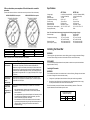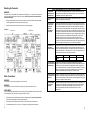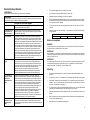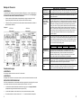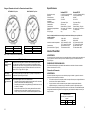
1
(…continuación)
Sin embargo, si el calentador de agua se instala en otra ubicación distinta de una vivienda familiar
individual, esta garantía está limitada a dos (2) años a partir de la fecha de la instalación y
funcionamiento originales.
Nota : La garantía no cubre los daños ocasionados por congelación.
Nota : La garantía no cubre los daños ocasionados por la formación de incrustaciones.
2.
3.
Otros componentes que no sean el intercambiador de calor: si otro componente (que no sea el
intercambiador de calor) presenta defectos en el material o la fabricación antes de un (1) año a
partir de la fecha de instalación original del calentador de agua, BBT proporcionará al propietario
nuevos componentes.
Verificación de la fecha de instalación original: cuando el propietario no puede verificar o
documentar la fecha de instalación original, el período de garantía se inicia en la fecha de fabricación
marcada en la etiqueta fijada al calentador de agua.
EXCLUSIONES
1.
ESTA GARANTÍA LIMITADA SERÁ LA GARANTÍA EXCLUSIVA DEL FABRICANTE Y EXCLUYE
TODAS LAS DEMÁS GARANTÍAS EXPRESAS O TÁCITAS (POR ESCRITO O DE PALABRA),
INCLUYENDO, ENTRE OTRAS, LAS GARANTÍAS DE COMERCIABILIDAD O IDONEIDAD PARA
UN FIN DETERMINADO.
2.
El fabricante no se responsabilizará de los daños imprevistos, resultantes, especiales o
contingentes, ni de los gastos que surjan directa o indirectamente de los defectos en el calentador
de agua o de su uso.
3.
El fabricante no se responsabilizará de los daños producidos por el agua que surjan directa o
indirectamente de los defectos en los componentes del calentador de agua o de su uso.
4.
El fabricante está exento de responsabilidad bajo esta garantía si:
a)
El calentador de agua o cualquiera de sus componentes se ha sometido a una mala
utilización, alteración, negligencia o accidente, o;
b)
El calentador de agua no se ha instalado en conformidad con la normativa y/o el reglamento
local aplicable de fontanería y/o vivienda, o;
c)
El calentador de agua no se ha instalado en conformidad con las instrucciones impresas del
fabricante, o;
d)
No existe un suministro continuo de agua potable en el calentador de agua.
5.
El propietario, y no el fabricante o su representante, se responsabilizará y pagará todos los daños
producidos por la mano de obra u otros gastos contraídos en el desmontaje y/o reparación del
equipo o daños producidos por el propietario a fin de reparar el equipo.
ALGUNOS ESTADOS NO PERMITEN QUE SE ESTABLEZCAN EXCLUSIONES O LIMITACIONES DE
DAÑOS IMPREVISTOS O RESULTANTES, POR LO QUE ES POSIBLE QUE LA ANTEDICHA
LIMITACIÓN NO LE SEA DE APLICACIÓN A USTED. ESTA GARANTÍA LE CONCEDE DERECHOS
JURÍDICOS ESPECÍFICOS, Y ES POSIBLE QUE USTED TENGA OTROS DERECHOS.
IMPORTANTE: EL PROPIETARIO DEBE GUARDAR ESTE CERTIFICADO
NOTA: La instalación de un calentador de agua se debe realizar de tal forma que, en caso de
pérdidas, el caudal de agua resultante no producirá daños en el área donde se instale.
La persona que instaló inicialmente la unidad es la más adecuada para proporcionar ayuda.
También puede llamar al número de teléfono de llamada gratuita de BBT 866-330-2729. Tenga a mano esta
guía cuando llame.
BBT NORTH AMERICA
Bosch Water Heating
340 Mad River
Waitsfield VT 05673
TOLL FREE: 866-330-2729
Fax: 802-496-6924
Bosch Group
www.boschhotwater.com
11.22.06
555-2028-10D
© 2006 Bosch Water Heating,
Waitsfield, VT all rights reserved
Important Safety Instructions
La temperatura del agua es demasiado alta
When using this electrical equipment, basic safety precautions should always be
followed, including the following:
1. READ AND FOLLOW ALL INSTRUCTIONS.
2.
This appliance must be grounded.
3.
Disconnect this product from the electrical supply before cleaning, servicing or removing the
cover.
4.
To reduce the risk of injury, close supervision is necessary when the product is used near
children or elderly persons.
5.
Warning: Mount the unit onto a flat section of wall, well away from any potential splashes of
water or spray and away from areas where direct moist or wet contact could occur .
6.
Warning: Do not install the heater in a location where it may be subject to freezing.
7.
Warning: Do not install a check valve or any other type of back flow preventer within ten feet of
the cold water inlet.
8.
The electrical installation must conform to current National Electrical Codes.
9.
Warning: Do not switch the heater on if you suspect that it may be frozen. Wait until you are
sure that it has completely thawed out.
El regulador de
temperatura está
demasiado alto
Gire el regulador de temperatura situado en la base del calentador de agua a la
izquierda para bajar la temperatura.
Hay
restricciones en
la fontanería
Las obstrucciones en la ruta del agua pueden reducir el flujo de agua que pasa por
el calentador y provocar un sobrecalentamiento. Compruebe que el filtro de entrada
del calentador, los aireadores de los grifos, las alcachofas de las duchas y los filtros
de toda la casa no tienen residuos. Compruebe que el flujo del lado de salida del
calentador con la tubería de agua caliente desconectada es correcto. Es posible
que tenga que abrir por completo la válvula de aislamiento de agua caliente. Los
caudales máximos de cada unidad son los siguientes: AE115 = 2,3 gpm (0,522
m3/h); AE125 = 3,5 gpm (0,795 m3/h).
La temperatura
del agua de
entrada es
excesiva
Compruebe que el calentador recibe únicamente agua fría. Este calentador de agua
no está diseñado para funcionar con aplicaciones de agua precalentada o de
recirculación de agua. Aumente el caudal si es posible. Quizás sea necesario
utilizar alcachofas de ducha y aireadores de un flujo mayor (en galones por minuto).
Mezcla fría, el
calentador se
desactiva
Si la temperatura del agua de entrada es superior a los 70º F (21º C) por la
ubicación geográfica, es posible que el agua del grifo salga muy caliente. Esto
supone que hay que agregar gran cantidad de agua fría al agua caliente para
alcanzar una temperatura de uso aceptable. Si se agrega demasiada agua fría, la
demanda del calentador de agua sin depósito se verá superada, lo que provocará
que el flujo del interior del calentador de agua disminuya hasta un nivel insuficiente
para que el calentador funcione, por lo que se desactivará. El resultado: por las
salidas sólo se obtendrá agua fría. Consulte el boletín de servicio TWH-E2-04 en el
sitio www.boschhotwater.com para ver otras soluciones para este problema.
La presión del
agua fluctúa
Si la presión del agua en el domicilio es irregular y el flujo de agua no es constante
cuando se abren los grifos, la temperatura del agua caliente también fluctuará. La
presión mínima del agua en el domicilio debe ser del 30 psi, o superior. Para las
personas con sistemas de pozo, el intervalo de presión recomendado es de 30 a 50
psi. La utilización de una válvula reguladora o reductora de presión es una forma
eficaz de mantener una presión constante del agua en el calentador. Se sugiere la
utilización de válvulas reductoras o reguladoras de la marca Watts, modelos 25AUB
de 3/4" o N35B de 3/4", o equivalentes.
Caudal irregular
Unos cambios muy grandes en el caudal pueden afectar negativamente a la
temperatura de salida del agua del calentador. Cuando se pasa de uno a varios
dispositivos de fontanería en uso al mismo tiempo, es posible que la temperatura
fluctúe. Manténgase dentro de las especificaciones del calentador. Consulte el
Gráfico 1 en la página 8.
La temperatura del agua fluctúa
10. The PowerStar is designed to heat potable cold water for domestic purposes. The maximum
inlet water temperature it can handle is 86 degrees F. Contact Bosch Water Heating before
specifying or installing the appliance in any other application.
11. Additional Canadian safety instructions:
a)
As per the Canadian Electrical Code, C22.1-02 Section 26-744, an auxiliary terminal block
must be fitted to the unit before connecting to the electrical supply (Kit Part N° “AE Canada
Kit”). (See Page 7).
b)
A green terminal (or a wire connector marked “G,” “GR,” “GROUND” or “GROUNDING”) is
provided within the control. To reduce the risk of electrical shock, connect this terminal or
connector to the grounding terminal of the electrical service of supply pane l with a
continuous copper wire in accordance with the Canadian Electrical Code, Part I.
c) This product shall be protected by a Class A ground fault circuit interrupter.
Contents
Specifications
Installing the PowerStar
Starting up the PowerStar
How the PowerStar works
Using the PowerStar
Spare Parts
Maintenance
Troubleshooting
Warranty
3
3
8
9
10
11
11
12
15
SAVE THESE INSTRUCTIONS
Keep this guide in a safe place once your unit has been installed.
You may need to refer to it for general instructions or future maintenance.
2
PowerStar
GARANTÍA LIMITADA DE 10 AÑOS
COBERTURA
BOSCH WATER HEATING (en lo sucesivo denominado BBT) garantiza este calentador de agua al
propietario original del mismo y en la ubicación de instalación original contra defectos en los materiales y
en la fabricación durante el período de tiempo indicado a continuación.
PERÍODO DE GARANTÍA
1.
Intercambiador de calor: si existen pérdidas o fallos en el intercambiador de calor antes de los diez
(10) años a partir de la fecha de instalación original del calentador de agua que estén ocasionados
por un defecto en el material o la fabricación, BBT proporcionará al propietario un nuevo calentador
del modelo actual equiparable.
(continuación…)
15
Utilice un ohmímetro para comprobar el fallo del elemento de encendido
prematuro
Specifications
(la lectura del ohmímetro indicará un circuito abierto cuando se produzca un fallo en el elemento)
MÓDULO IZQUIERDO Vista superior
MÓDULO DERECHO Vista superior
Voltage supply
Amperage
Maximum output
Temperature control range
Pressure range
Minimum flow rate
Maximum flow rate
Dimensions (excl. water couplers)
Weight (without water)
AE115 Unit
AE125 Unit
2 x 240V AC (Canada 240VAC)
2 x 40 A (Canada 80 A)
17.25 kW
95°F to 131°F
15 psi to 150 psi
0.6 US gal / min
See Graph 1, Page 8
15½” H x 151/4” W x 4½” D
20 lbs
3 x 240V AC (Canada 240VAC)
3 x 40 A (Canada 120 A)
26.85kW
95°F to 131°F
15 psi to 150 psi
0.8 US gal / min
See Graph 1, Page 8
15½” H x 151/4” W x 4½” D
22 lbs
Note: The unit will work at lower supply voltages but the following changes will apply:
Maximum output
15kW at 220V
22.5kW at 220V
13kW at 208V
20kW at 208V
Temperature control range
87°F to 116°F at 220V
87°F to 116°F at 220V
82°F to 108°F at 208V
82°F to 108°F at 208V
Maximum flow rate
84% of maximum at 220V
84% of maximum at 220V
(refer to Graph 1, Page 8)
75% of maximum at 208V
75% of maximum at 208V
Sondas
Exterior a exterior
Intermedio a intermedio
Interior a interior
Lectura en ohmios
10,5 ± 0,5 ohmios
11,5 ± 0,5 ohmios
15,0 ± 1 ohmios
Sondas
Exterior a exterior
Intermedio a intermedio
Interior a interior
Lectura en ohmios
10,5 ± 0,5 ohmios
11,5 ± 0,5 ohmios
21,0 ± 1 ohmios
Nota: En el modelo AE115, el elemento intermedio no está instalado.
Flujo de agua insuficiente
Hay restricciones
en la fontanería
Las obstrucciones de la ruta del agua pueden reducir el flujo de agua que pasa
por el calentador. Compruebe que el filtro de entrada del calentador, los
aireadores de los grifos, las alcachofas de las duchas y los filtros de toda la casa
no tienen residuos. Compruebe que el flujo del lado de salida del calentador con
la tubería de agua caliente desconectada es correcto. Los caudales máximos de
cada unidad son los siguientes: AE115 = 2,3 gpm (0,522 m3/h); AE125 = 3,5 gpm
(0,795 m3/h).
Installing the PowerStar
WARNING:
If water supply has a high mineral content, a water softening system is strongly recommended. Damage
to the water heater resulting from scale or hard minerals will not be covered under warranty.
DISCLAIMER:
In the Commonwealth of Massachusetts a licensed plumber or electrician must perform the installation.
(Approval number: P1-09-25).
Locating the Powerstar
WARNING:
Do not install the water heater in an area where there is a chance of freezing. Damage to the water heater
as a result of freezing will not be covered under warranty.
La presión de la
alimentación de
agua es
demasiado baja
Compruebe que la alimentación del agua de entrada tiene una presión de al
menos 30 psi. Para las personas con sistemas de pozo, el intervalo de presión
recomendado es de 30 a 50 psi.
•
If being used in a public place, locate the heater out of easy reach to discourage vandalism.
•
Mount the unit onto a flat section of wall, well away from any potential splashes of water or spray
and away from areas where direct moist or wet contact could occur.
Las válvulas de
corte de salida
están
configuradas a un
nivel demasiado
bajo
Ajuste la válvula de salida suministrada por el instalador como se describe a
continuación:
•
Abra completamente las válvulas de corte de entrada y salida del
calentador, suministradas por el instalador. Si no las hubiera, instálelas
antes de continuar.
•
Abra completamente el agua caliente del dispositivo de fontanería que utilice
agua caliente que esté instalado en el punto más elevado y que reciba
servicio del calentador (por ejemplo, una bañera).
•
Cierre lentamente la válvula de corte de salida, reduciendo el caudal de
agua hasta que la temperatura del grifo de agua caliente corresponda a los
valores del Gráfico 1 de la página 8 del manual o hasta alcanzar la
temperatura del agua.
Should it be necessary to service the Powerstar, observe the following clearances. These are not
required clearances, but would facilitate any service work.
14
Recommended minimum
clearances for servicing
Top
Sides
12”
0”
Bottom
Front
6”
12”
3
Mounting the Powerstar
El agua está demasiado fría. La luz de neón está encendida
WARNING:
The heater must only be installed in the orientation shown in Diagram 1 i.e., mounted in a vertical position
with the water fittings located at the bottom of the heater. Under no circumstances should the heater
be mounted differently.
•
Undo the retaining screws on the front cover and take the cover off the heater. Hold the back plate
in position against the wall and mark the four mounting holes
•
Drill the holes and secure the heater using the four wood screws supplied.
Diagram 1
AE115 Unit
AE125 Unit
El regulador de
temperatura está
demasiado bajo
Gire el regulador de temperatura situado en la base del calentador de agua a la
derecha para subir la temperatura. Consulte el gráfico 1 para ver la variación de
temperatura de salida con respecto al caudal.
El flujo de agua es
excesivo
Ajuste el flujo de agua a las especificaciones del calentador de agua. Consulte el
Gráfico 1 de la página 8 de este manual.
Uno o varios de
los disyuntores
térmicos del
módulo de
calentamiento
ha(n) fallado
Desconecte la alimentación de la unidad; retire la tapa y coloque los disyuntores
térmicos sobre cada módulo de calentamiento. Intente restablecer cada disyuntor
con el botón de restablecimiento situado en el centro del disyunto r. Determine y
resuelva la causa del sobrecalentamiento. Las obstrucciones de la ruta del agua
pueden reducir el flujo de agua que pasa por el calentador y provocar que el agua
se recaliente. Compruebe que todos los filtros de admisión del calentador y todas
las salidas que abastece están limpios y sin residuos. Asegúrese de que el agua
que llega al calentador no esté precalentada. Este calentador de agua se ha
diseñado para funcionar sólo con agua fría. Si el disyuntor térmico no se
restablece, compruebe la continuidad de cada disyuntor (menos de 0,5 ohmios).
Si alguno de los disyuntores tuviera una lectura superior a 0,5 ohmios o estuviera
abierto, es posible que esté defectuoso y que sea necesario cambiarlo.
La tensión de la
alimentación
eléctrica ha caído
Probablemente haya un problema en la alimentación eléctrica. Mida la tensión del
bloque de terminales del calentador de agua mientras lo hace funcionar con un
caudal y una temperatura máximos. Los modelos AE115/AE125 funcionan a una
tensión nominal de 240 V, y funcionan a 220 V y 208 V, con una salida menor. La
salida variará de acuerdo con las siguientes relaciones:
Voltios
Relación de
salida
Water Connections
WARNING:
Do not apply heat or solder to connections or pipe if they are already connected to the unit.
DISCLAIMER:
220
0,84
240
1,0
La temperatura del
agua de entrada es
demasiado baja
Compruebe si el calentador tiene el tamaño apropiado para su ubicación
geográfica. Gire el regulador de temperatura de la base del calentador de agua a
la derecha, hasta el tope, para alcanzar la temperatura máxima. Asegúrese de
que los caudales están dentro de las especificaciones del calentador. Consulte el
Gráfico 1 de la página 8 del manual. Se recomienda el uso de una válvula de
aislamiento en la salida de agua caliente para controlar el caudal.
Una de las fuentes
de alimentación no
está activa
Solicite a un electricista con licencia que compruebe que el bloque de terminales
del interior del calentador de agua tiene una tensión correcta. Compruebe que los
disyuntores del calentador no están activados. Consulte el apartado «Conexiones
eléctricas» de la página 5 de este manual.
Fallo del elemento
de encendido
prematuro
Desactive la alimentación de la unidad y retire la tapa. Utilice un ohmímetro para
comprobar que la resistencia de cada elemento es la correcta. Si las lecturas no
corresponden a las especificaciones indicadas, póngase en contacto con el
servicio de Asistencia técnica (866) 330-2729 para que le den nuevas
instrucciones.
WARNING:
Do not install a non-return check valve within 10 feet of the inlet.
208
0,75
In the Commonwealth of Massachusetts a pressure relief valve shall be installed on the cold water side by
a licensed plumber. (MGL 142 Section 19, Approval number P1-09-25)
•
The heater must be connected directly to the main cold water supply and not to pre-heated water.
(The inlet water temperature must not be greater than 86°F.)
•
The heater must be installed with shutoff valves on both the inlet and outlet connections.
•
It is recommended that you use ¾ inch or ½ inch copper or high-pressure flex connections.
4
13
Resolución de problemas
ADVERTENCIA
Apague siempre el suministro eléctrico en la unidad antes de retirar la tapa.
IMPORTANTE:
Si no puede realizar las tareas que se enumeran a continuación o requiere ayuda, póngase en contacto
con el instalador original o un electricista debidamente acreditado.
•
Do not use plastic piping within 3 feet on either side of heater.
•
Use Teflon tape for sealing pipe threads. Do NOT use pipe dope.
•
Remember to keep the hot water pipe runs as short as possible.
•
After the heater has been plumbed, and before you wire it, flush it with water to remove any debris
or loose particles. Heater must be full of water and air purged before power is turned on. Failure to
do so may make the heater inoperable.
Sólo agua fría. Luz de neón apagada
El flujo es insuficiente
Compruebe que el flujo de salida es igual o superior a 0,8 gpm (0,182 m3/h),
el mínimo necesario para activar la unidad.
•
The inlet and outlet connections are clearly marked on the heater. They each have a ¾ inch NPT
connector.
El suministro de agua
está conectado a la
salida de la unidad
Compruebe que las conexiones de las tuberías son correctas (consulte el
Diagrama 1, página 4). Vuelva a conectar el suministro de agua a la entrada
de la unidad (marcada en azul).
•
Check the pressure of the main water supply. To operate correctly, the heater needs the following
running pressures:
Cruce de tuberías
Para comprobar si hay algún cruce de tuberías, desactive la alimentación
eléctrica del calentador. Cierre la válvula de corte de agua fría suministrada
por el instalador (si no hubiera ninguna, instálela antes de continuar). Abra
todos los grifos de agua caliente que alimenta el calentador. Espere 5 minutos
y compruebe todos los grifos. Cualquier flujo de agua indicaría que hay un
cruce de tuberías. Consulte a un fontanero o técnico local para que lo ayude a
corregir el problema. Para volver a poner el calentador en marcha, instale la
cubierta, abra la alimentación de la entrada de agua al calentador y abra
todos los grifos de agua caliente. Deje los grifos abiertos hasta que no salga
aire de los dispositivos que utilizan agua (por ejemplo, los grifos). Cierre todos
los grifos de agua caliente. Active la alimentación eléctrica del calentador.
Vuelva a poner el calentador en marcha. Este procedimiento evitará que los
elementos calentadores se pongan en marcha en seco.
El transductor de flujo
no gira
Uno o varios de los
disyuntores térmicos
del módulo de
calentamiento ha(n)
fallado
No llega electricidad al
calentador o uno de
los suministros ha
fallado
12
Desactive la alimentación eléctrica del calentador y retire la tapa. Observe si
el transductor de flujo «gira» al hacer fluir el agua. Tenga presente que el
transductor de flujo gira a gran velocidad y puede parecer detenido cuando,
de hecho, está en marcha. Se recomienda observar el transductor de flujo sin
agua. Después, abra un grifo de agua caliente, mientras observa el
transductor de flujo. Si no gira, retírelo y lávelo con agua. Consulte el
apartado de asistencia técnica de www.boschhotwater.com para obtener
información más detallada sobre cómo desmontar el transductor de flujo.
Desconecte la alimentación del calentador; retire la tapa y coloque los
disyuntores sobre cada módulo de calentamiento. Intente restablecer cada
disyuntor con el botón de restablecimiento situado en el centro del disyuntor.
Determine y resuelva la causa del sobrecalentamiento. Las obstrucciones de
la ruta del agua pueden reducir el flujo de agua que pasa por el calentador y
provocar que el agua se recaliente. Compruebe que todos los filtros de
admisión del calentador y todas las salidas que abastece están limpios y sin
residuos. Asegúrese de que el agua que llega al calentador no esté
precalentada. Este calentador de agua se ha diseñado para funcionar sólo
con agua fría. Si el disyuntor térmico no se restablece, compruebe la
continuidad de cada disyuntor (menos de 0,5 ohmios). Si alguno de los
disyuntores tuviera una lectura superior a 0,5 ohmios o estuviera abierto, es
posible que esté defectuoso y que sea necesario cambiarlo.
Haga que un electricista con licencia compruebe que el cableado es correcto
y que el bloque de terminales del interior del calentador de agua tiene una
tensión adecuada. Consulte el apartado «Conexiones eléctricas» de la página
5 de este manual.
Recommended water pressures
Min water pressure 15 psi (1 Bar)
Max water pressure
150 psi (10 Bar)
Electrical connections
WARNING
The unit must be wired by a qualified electrician, in accordance with the current version of the National
Electrical Code US) or Canadian Electric Code (Canada).
IMPORTANT
When the heater is not within sight of the electrical circuit breakers, a circuit breaker lockout or additional
local means of disconnection for all non-grounded conductors must be provided that is within sight of the
appliance. (Ref NEC 422.31.)
IMPORTANT
As per the Canadian Electrical Code, C22.1-02 Section 26-744, an auxiliary terminal block must be fitted
to the heater before connecting to the electrical supply. This is available as a kit from Bosch Water
Heating, Part Number “AE Canada Kit”. (Contact 866-330-2729).
US wiring
•
The minimum recommended wire size is 8 AWG. (The terminal block will accept cables up to 6
AWG size.)
•
The cable entry is via the 1 ¼ inch cable entry hole on the bottom right hand edge of the back plate.
•
Strip back the insulation on the power wires about ½ inch. Connect the live wires to the terminals
marked “L1” and “L2.” There are two pairs of live wires in the AE115 and three pairs of live wires in
the AE125. (See Diagrams 2 or 3 on page 6).
•
Any insulation on the ground wires should be stripped back about ¾ inch. The ground leads must be
connected to the pillar terminal marked “GR”. (See Diagrams 2 and 3, Page 6).
•
Make sure the terminal block screws are tightened securely. Loose connections can cause wires to
heat up.
•
Make sure that the ground wires are wrapped around its terminal stud and into the saddle washer.
The nut should be tightened securely.
•
Attach the front cover and tighten the retaining screws.
5
Diagram 2
AE115 Terminal Block Connection
Piezas de recambio
The AE115 requires two independent 240V AC circuits protected by two separate and independent
double pole breakers (as shown) rated at 40 A each.
Diagram 3
Nº de pieza
Descripción (Consulte
el Diagrama 1, Pagina 4)
93 793770
93 793771
93 793772
93 793773
93 793842
93 793774
93 793775
93 793776
93 793843
93 793844
93 793779
93 793845
93 793846
93 793784
93 793847
93 793848
93 793849
93 793850
Bloque terminales 4 salidas (AE115)
Bloque terminales 6 salidas (AE125)
Tapa frontal (blanca)
Disyuntor térmico (AE115)
Disyuntor bipolar (AE125)
Transductor de flujo
Caja de PCI (tapa)
Caja de PCI (base)
PCI de control (AE115)
PCI de control (AE125)
Pomo de ajuste
Sellos del anillo de O
Tornillos para el calentador
Filtro de entrada 3/4"
Calentador Uno (AE115)
Calentador Dos (AE115)
Calentador Uno (AE125)
Calentador Dos (AE125)
Para obtener información adicionales,
consulte con su distribuidor local.
SI TIENE ALGUNA PREGUNTA
SOBRE MANTENIMIENTO O
INSTALACIÓN, LLAME AL TELÉFONO
866-330-2729 (Toll Free)
Fax: 802-496-6924
BBT NORTH AMERICA
Bosch Group
www.boschhotwater.com
AE125 Terminal Block Connection
Mantenimiento
Compruebe el filtro de agua de entrada una vez al año
•
•
•
•
•
Desconecte la válvula de aislamiento del agua fría del calentador suministrada por el instalador. Si
no la hubiera, instálela antes de continuar.
Abra el grifo de agua caliente más cercano para aliviar la presión de las tuberías.
Coloque un cubo bajo la conexión de entrada de agua fría del calentador, para recoger el agua
drenada.
Afloje la conexión de las tuberías de agua fría (parte inferior derecha del calentador) para acceder
al filtro (consulte el Diagrama 1, página 4).
Saque el filtro, límpielo con agua y compruebe que no presenta daños. Si el filtro está dañado,
cámbielo.
The AE125 requires three independent 240V AC circuits protected by three separate and independent
double pole breakers (as shown) rated at 40 A each.
6
11
Diagrama 4: Diagrama de conexiones internas para una unidad monofásica AE125. (AE115 no tiene
calentadores 5 y 6 cabidos y no utiliza dos suministros). (En Canadá, durante la instalación se
coloca un bloque de terminales auxiliar).
Canada wiring – auxiliary terminal block and connections
Fitting the auxiliary terminal block (see diagram below).
AE115
AE125
NOT
FOR
U.S.A.
•
Connect the red wires from the left hand terminal of the new block to the L1 terminals in the unit.
(There are two red wires required in the AE115 and three in the AE125).
•
Connect the blue wires from the right hand terminal of the new block to the L2 terminals in the unit.
(There are two blue wires required in the AE115 and three in the AE125).
•
Push and click the auxiliary terminal block onto the louvered rail in the backplate.
Connecting the supply cable - Canada only - not for the USA.
•
The AE115 requires an 80A 240V AC
single phase supply protected by an 80A
double pole circuit breaker.
•
The power cable size and the installation must be in accordance with the Canadian Electrical Code,
C22.1-02.
No utilice esta unidad si cree que se puede congelar, ya que se podría dañar gravemente la unidad. Espere
hasta que esté seguro de que se haya descongelado completamente.
•
The incoming hole diameter on auxiliary terminal block can accept up to 1/0 AWG size cables.
•
The cable entry is via the 1 ¼ inch cable entry hole on the bottom right hand edge of the backplate.
•
•
•
Strip back the insulation on the power wires about ½ inch. Connect the ungrounded conductors to
the terminals “L1” and “L2” on the auxiliary terminal block.
•
Any insulation on the ground wire should be stripped back about ¾ inch. The ground lead must be
connected to the pillar terminal marked “GR.”
•
Make sure the terminal block screws are tightened securely. Loose connections can cause wires to
heat up.
•
Make sure that the ground wire is wrapped around its terminal stud and into the saddle washer. The
nut should be tightened securely.
•
Attach the front cover and tighten the retaining screws.
Uso del PowerStar
ADVERTENCIA
•
•
•
10
Compruebe que está conectado el suministro eléctrico en el panel de interruptores.
Abra COMPLETAMENTE la llave de agua caliente. La temperatura del agua caliente se puede
cambiar ajustando el disco de temperatura situado en la cara inferior de la unidad (El disco ajusta
normalmente la temperatura entre 35°C y 55°C. El disco de temperatura viene ajustado de fábrica
en la posición más baja).
Existen disyuntores internos de seguridad que funcionarán si se produce un sobrecalentamiento en
la unidad. Si se dispara un disyuntor térmico, se debe reajustar por un electricista cualificado.
Si se ha utilizado recientemente la unidad, deje circular el agua unos segundos para estabilizar la
temperatura. Inicialmente podría salir un fuerte chorro de agua muy caliente, que se encont raba en
las tuberías desde un uso anterior.
Si también se abre una segunda salida conectada a la unidad, el agua caliente será compartida
entre las dos salidas.
•
The AE125 requires a 120A 240V AC
single phase supply protected by a 120A
double pole circuit breaker.
7
Starting up the PowerStar
•
Para la unidad AE115, utilice una válvula esférica y asegúrese de que el caudal no sobrepasa los
8,7 litros / minuto.
Checking for leaks and purging air
•
Para la unidad AE125, utilice una válvula esférica y asegúrese de que el caudal no sobrepasa los
13,2 litros / minuto.
•
Verify all circuit breakers supplying power to the water heater are turned off.
•
Open all hot water taps supplied by the water heater and inspect all water connections for leaks.
•
With all hot water taps still open, inspect each tap to ensure all air in the lines has been purged out.
•
With the air purged and taps still flowing, turn on all circuit breakers supplying the water heater.
•
Close all hot water taps and proceed to the next section.
IMPORTANTE
Adjusting the temperature dial
•
Nota: Estas cifras están basadas en una temperatura del agua de entrada de 12ºC y un voltaje de
entrada de 240 voltios. Si la temperatura del agua de entrada es inferior a 12ºC, o si el voltaje de
entrada es inferior a 240 voltios, la temperatura de salida será inferior a la mostrada en el Gráfico 1.
Si se desea una temperatura del agua de salida más alta, reduzca el caudal y/o proporcione un
suministro a la unidad de 240 voltios.
Antes de abandonar el lugar de instalación, el instalador debe mostrar la unidad al usuario y proporcionarle
esta guía.
The temperature adjustment is made using the dial on the bottom edge of the unit. The adjustment
is between approximately 95°F and 135°F. Turning the dial clockwise increases the temperature
setting as indicated by the marking on the unit.
Funcionamiento del PowerStar
Adjusting the flow
•
El PowerStar calienta agua continuamente a medida que fluye por los módulos calefactores.
•
Open fully both inlet and outlet shut-off valves at the heater, then :
•
•
El control electrónico monitoriza el caudal y la temperatura del agua de entrada, y luego conecta el
número necesario de módulos para alcanzar la temperatura ajustada en el disco de ajuste.
Turn on fully the highest flowing hot water faucet (e.g., bathtub) served by the water heater.
•
Adjust the outlet shut-off valve until the water flow rate from the hot faucet corresponds to the value
given in Graph 1 below.
•
A medida que cambia el caudal o la temperatura del agua de entrada, el sistema electrónico ajusta
el número de módulos calefactores que se utilizan, con el fin de mantener la temperatura de salida.
•
La temperatura del agua de salida puede cambiar ligeramente a medida que cambia el caudal
debido a los cambios de potencia, a medida que se conectan y desconectan los módulos.
•
La temperatura del agua de salida también puede variar si se sobrepasa el caudal máximo
(consulte el Gráfico 1) o si cambia el voltaje de entrada.
•
Cada módulo calefactor está protegido por un disyuntor térmico electromecánico. Si la temperatura
de uno de los módulos calefactores sube demasiado, el disyuntor se disparará y cortará el
suministro eléctrico en dicho módulo calefactor. Si se dispara el disyuntor, debe ser reajustado por
un técnico de mantenimiento cualificado. Este disyuntor sólo se disparará en circunstancias
excepcionales.
•
La unidad AE115 se suministra con dos voltajes independientes, y la unidad AE125 se suministra
con tres voltajes independientes. (En Canadá, la unidad sólo dispone de un suministro de voltaje).
•
Según el territorio del país, la temperatura del suministro de agua puede variar entre algo más de
4ºC en invierno y 21ºC en verano, con un promedio de 12,7ºC.
Graph 1
Outlet Temperature vs Maximum Flow Rate Setting
(based on incoming water temperature of 55°F)
5.00
Max Flow Rate (US gal / min)
4.50
4.00
3.50
AE125 Heater
3.00
2.50
2.00
AE115 Heater
1.50
1.00
95
100
105
110
115
120
Outlet Temperature (°F)
8
125
130
135
9
Empezar a utilizar el PowerStar
For example:
Comprobación de fugas y purga de aire
•
For the AE115 unit, using the outlet ball valve, ensure the flow rate does not exceed 2.3 gallons /
minute.
•
For the AE125 unit, using the outlet ball valve, ensure the flow rate does not exceed 3.5 gallons /
minute.
•
Compruebe que todos los disyuntores que llevan alimentación eléctrica al calentador de agua están
desactivados.
•
Abra todos los grifos de agua caliente que alimenta el calentador de agua y examine todas las
conexiones de las tuberías de agua, por si hubiera fugas.
•
Con todos los grifos de agua caliente aún abiertos, examine todos los grifos para asegurarse de que
se ha purgado todo el aire de los conductos.
•
Una vez purgado el aire, con los grifos aún abiertos, active todos los disyuntores del calentador de
agua.
•
Cierre todos los grifos de agua caliente y vaya al siguiente apartado.
Note: These figures are based on an inlet water temperature of 55°F and a supply voltage of 240
volts. If the inlet water temperature is lower than 55°F, or if the supply voltage is less than 240 volts,
then the outlet temperature will be lower than what is shown in Graph 1. If a higher outlet water
temperature is desired, then reduce the flow rate and/or supply the unit with 240 volts.
IMPORTANT
Before leaving the site, the installer should demonstrate the unit to the user and give them this guide.
Ajuste del disco de temperatura
•
El ajuste de la temperatura se realiza con el disco situado en el borde inferior de la unidad. El
ajuste está entre 35ºC y 55ºC aproximadamente. Si se gira el disco en el sentido de las agujasdel
reloj se aumenta el ajuste de temperatura según lo indica la marca en la unidad.
Ajuste del caudal
•
Abra completamente las válvulas de cierre de entrada y salida en el calentador, y luego:
•
Abra completamente la llave de agua caliente (ej.: bañera) más próxima a la conexión de salida.
•
Ajuste la válvula de cierre de salida hasta que el caudal de agua de la llave de agua caliente
coincida con el valor indicado en el Gráfico 1 debajo.
Gráfico 1
8
Ejemplo:
How the PowerStar works
•
The PowerStar heats water continuously as it flows through the heater modules.
•
The electronic control PCB monitors the flow rate and the incoming water temperature and then
switches on the required number of heater elements to reach the temperature set by the adjustment
dial.
•
As the flow rate or the incoming water temperature changes, the electronic control adjusts the
number of heater modules used so that the outlet temperature is maintained .
•
The outlet water temperature can change slightly as the flow rate changes due to the steps in power
as different heater modules are switched on and off.
•
The outlet water temperature can also vary if the maximum flow rate is exceeded (see Graph 1) or if
the supply voltage changes.
•
Each heater module is protected by an electro-mechanical thermal cut-out. If the temperature of any
of the heater modules gets too high, then the cut-out will trip and cut the power to that heater
module. If the cut-out trips, it must be reset while the circuit breakers are off. If you are not
comfortable or qualified to perform this task, consult the original installer or a licensed electrician.
This cut-out will only trip in exceptional circumstances.
•
The AE115 unit is supplied from two independent voltage supplies and the AE125 unit from three
independent voltage supplies. (In Canada the unit has just one voltage supply).
•
Depending on the region of the country, the temperature of the water supply can vary between 40°F
in winter to 70°F in summer, with an average of 55°F.
9
Diagram 4: Internal wiring schematic for single phase AE125 unit. (AE115 does not have Elt 5 & 6 fitted
and uses two supplies). (In Canada an auxiliary terminal block is fitted durin g installation).
Cableado en Canadá: conexiones y bloque de terminales auxiliares
Instalación del bloque de terminales auxiliar (verse el Diagrama).
AE115
AE125
•
Conecte los cables rojos del terminal izquierdo del nuevo bloque en los terminales L1 del equipo. (El
AE115 requiere dos cables rojos y el AE125 requiere tres cables).
•
Conecte los cables azules del terminal derecho del nuevo bloque en los terminales L2 del equipo. (El
AE115 requiere dos cables azules y el AE125 requiere tres cables).
•
Meta y acople el bloque de terminales auxiliar sobre el raíl apersianado de la placa posterior.
Conexión del cable de suministro
•
El AE115 requi er e un s umi ni st ro
monofásico de 80A 240V CA protegido por
un interruptor bipolar de 80A.
WARNING
•
Do not use the unit if you think it may be frozen, as this could result in serious damage to the unit. Wait
until you are sure that it has completely thawed out before you switch it on.
El tamaño y la instalación del cable de alimentación debe estar en conformidad con la Normativa
Eléctrica Canadiense.
•
El diámetro del casquillo de entrada y el bloque de terminales auxiliar puede aceptar tamaños de cable
de 1/0 AWG.
•
La entrada del cable se realiza a través del orificio de entrada de 1 ¼" situado en el borde inferior
derecho de la placa posterior.
•
Pele el aislamiento de los cables de alimentación, aproximadamente 1,2 cm. Conecte los cables con
corriente en los terminales "L1" y "L2" situados en el bloque de terminales auxiliar.
•
Pele el aislamiento del cable de toma de tierra, aproximadamente 1,9 cm. El hilo de toma de tierra
debe conectarse al terminal de poste con la marca "GR".
•
Asegúrese de que los tornillos de los bloques de terminales están firmemente apretados. Las
conexiones sueltas pueden provocar el calentamiento de los cables.
•
Asegúrese de que el cable de toma de tierra está enrollado en el vástago del terminal y en la
arandela de asiento. La tuerca debe apretarse firmemente.
•
Coloque la cubierta delantera y apriete los tornillos de fijación.
Using the PowerStar
•
•
•
•
•
10
Check that the power is switched on at the circuit breaker panel.
Turn on the hot water faucet FULLY. The hot water temperature can be changed by adjusting the
temperature dial on the bottom surface of the unit. (The dial adjusts the temperature typically
between 95°F and 131°F. The factory sets the temperature dial at the lowest position.)
There are internal safety thermal cut-outs which will trip if the unit overheats. If the cut-out trips, it
must be reset while the circuit breakers are off. If you are not comfortable or qualified to perform this
task, consult the original installer or a licensed electrician.
If the unit has been used recently, run the water through for a few seconds to let the temperature
cool down. You may initially get a short burst of very hot water that was in the plumbing lines from
previous use.
If a second outlet connected to the unit is also turned on, the hot water will be shared between the
two.
•
El AE125 requiere un suministro
monofásico de 120A 240V CA protegido
por un interruptor bipolar de 120A.
7
Diagrama 2
AE115 Conexión del bloque de terminales
Spare Parts
El AE115 requiere dos circuitos independientes de CA de 240V protegidos por dos conmutadores bipolares
separados e independientes (según se muestra) con un régimen de 40 A cada uno.
Diagrama 3
Part
Number
Description
(Refer to Diagram 1, Page 4)
93 793770
93 793771
93 793772
93 793773
93 793842
93 793774
93 793775
93 793776
93 793843
93 793844
93 793779
93 793845
93 793846
93 793784
93 793847
93 793848
93 793849
93 793850
4 way term. block (for AE115)
6 way term. block (for AE125)
Front cover (white)
Thermal cut-out (AE115)
Double pole cut-out (AE125)
Flow transducer
PCB enclosure (lid)
PCB enclosure (base)
Control PCB (for AE115)
Control PCB (for AE125)
Adjustment knob
O Ring set
Fixing screws for heater flange
¾” Inlet filter screen
Heater element assembly 1 (AE115)
Heater element assembly 2 (AE115)
Heater element assembly 1 (AE125)
Heater element assembly 2 (AE125)
For further information ask your
local dealer.
FOR SERVICE AND INSTALLATION
QUESTIONS CALL TOLL FREE:
866-330-2729 (Toll Free)
Fax: 802-496-6924
BBT NORTH AMERICA
Bosch Group
Bosch Water Heating
340 Mad River Park
Waitsfield, VT 05673
Phone 866-330-2729
Fax 802-496-6924
www.boschhotwater.com
[email protected]
AE125 Conexión del bloque de terminales
Maintenance
Check inlet water filter screen once a year
•
Shut off the installer supplied cold water isolation valve to the heater. If one is not installed, install
before proceeding.
•
Open nearest hot water tap to relieve pressure in the plumbing lines.
•
Position a bucket under the cold water inlet connection of the heater to catch any water that may
drain.
•
Loosen cold water plumbing connection (bottom right of heater) to access filter screen (See Diagram
1, Page 4).
•
Remove filter, clean with water and inspect for damage. If the filter is at all damaged, it should be
replaced.
El AE125 requiere tres circuitos de CA de 240V protegidos por tres conmutadores bipolares separados e
independientes con un régimen de 40 A cada uno.
6
11
Troubleshooting
WARNING
Always switch off the electricity supply to the unit before you remove the cover.
IMPORTANT:
If you are unable to perform the tasks listed below, or need additional assistance please contact your
original installer/licensed electrician.
Cold water only – Neon light off
•
No utilice tuberías plásticas a menos de 3 pies (1 m) del calentador.
•
Utilice cinta de teflón para sellar las roscas de las tuberías. NO utilice aditivos para tuberías.
•
Recuerde mantener la tubería de agua caliente lo más corta posible.
•
Cuando se haya realizado la instalación de fontanería y antes de que conecte la unidad, enjuáguela
con agua para quitar la suciedad o las partículas sueltas. En caso contrario, es posible que no
funcione la unidad.
•
Las conexiones de entrada y salida están claramente identificadas en la unidad. Cada una dispone
de un conector NPT de ¾".
Flow rate is too
low
Verify the flow rate out of fixture is at or above the minimum activation rate
required for the unit to activate. (Activation rates: AE115 = 0.6 GPM, AE125 = 0.8
GPM).
•
Instale una válvula esférica en la línea de agua fría. Esta válvula se puede utilizar para cerrar el
suministro de agua fría en la unidad si hace falta realizar un mantenimiento, o para reducir el caudal
de agua si es demasiado alto.
The water supply
is connected to
the outlet of the
unit
Verify plumbing connections are correct (See Diagram 1, Page 4). Reconnect the
water supply to the inlet of the unit (marked blue).
•
Compruebe la presión de la fuente principal de agua. Para operar correctamente el calentador, se
requieren las siguientes presiones de funcionamiento :
Plumbing
crossover
To test for a plumbing crossover, turn off power supply to the heater. Close
installer supplied cold water shut off valve (if none installed, install before
proceeding). Open all hot water taps supplied by the heater. Wait 5 minutes and
check all taps. Any water running is a sign of a plumbing crossover. Consult a
local plumber or service person for help in correcting a plumbing crossover. To
return the heater to service, reinstall cover, open the inlet water supply to the
heater and open all hot water taps. Let all taps run until there is no air coming out
of the fixtures. Shut off all hot water taps. Turn power supply on to the heater.
Return heater to service. (This procedure will prevent the heating elements from
burning out).
The flow
transducer is not
spinning
One or more of the
heating module
thermal cut-outs
has tripped
No electricity at
the heater or one
of the supplies has
failed
12
Presiones de agua recomendadas
Presión mín. de agua 15 psi (1 bar)
Turn off the power supply to the heater and remove the cover. Observe if the flow
transducer "spins" when the water is turned on. Please note the flow transducer
spins at a high speed and can appear to be stopped when actually spinning. It is
recommended to observe the flow transducer without water flowing, then turn on a
hot water tap while observing the flow transducer. If the flow transducer is not
spinning, remove and flush flow transducer. See the technical support section of
www.boschhotwater.com for more detailed instruction on removing the flow
transducer.
Presión máx. de agua
150 psi (10 bar)
Conexiones eléctricas
ADVERTENCIA
Esta unidad debe ser conectada por un electricista cualificado, de acuerdo con la versión actual del
National Electrical Code (EE.UU.) o el Canadian Electric Code (Canadá).
IMPORTANTE
Cuando el PowerStar se instale fuera de la vista de interruptores eléctricos, se debe suministrar un bloqueo
de interruptor u otra forma de desconexión para todos los conductores sin toma de tierra, a lavista del
equipo. (Ref NEC 422.31.)
IMPORTANTE
Debe conectarse un bloque de terminales auxiliar en la unidad antes de conectar el suministro
eléctrico. Este bloque se puede obtener de BBT en forma de kit, nº de pieza "AE Canada Kit".
(Telefono de contacto 866-330-2729).
Cableado en EE.UU.
Turn off the power to the heater, remove the cover and locate thermal cutouts on
the top of each heating module. Try resetting each cutout by pushing the reset
button located in the center of the cutout. Determine and fix the cause of the
overheating. Obstructions in the water path can restrict the flow of water through
the heater causing it to overheat. Verify the heater’s inlet filter screen and all
outlets served by the heater are clear of debris. Ensure the heater is not being fed
preheated water. This water heater is designed for a cold water supply only. If
thermal cut out does not reset, check for continuity through each cutout (less than
0.5 Ohms). If any cutout reads more than 0.5 Ohms or open, then it may be
defective and should be replaced.
•
El tamaño mínimo de cable es de 8 AWG. (El bloque de terminales acepta cables de hasta 6 AWG).
•
La entrada del cable se realiza a través del orificio de entrada de 1¼" situado en el borde inferior
derecho de la placa posterior.
•
Pele el aislamiento de los cables de alimentación, aproximadamente 1,2 cm. Conecte los cables
con corriente a los terminales con la marca "L1" y "L2". Existen dos pares de cables con corriente en
el AE115 y tres pares de cables con corriente en el AE125.
•
Pele el aislamiento del cable de toma de tierra, aproximadamente 1,9 cm. El hilo de toma de tierra
debe conectarse al terminal de poste con la marca "GR" (consulte los Diagramas 2 y 3).
Have a licensed electrician verify proper wiring and adequate voltage on the
terminal block inside the water heater. See the “Electrical connections” section on
Page 5 of this manual.
•
Asegúrese de que los tornillos de los bloques de terminales están firmemente apretados. Las
conexiones sueltas pueden provocar el calentamiento de los cables.
•
Asegúrese de que el cable de toma de tierra está enrollado en el vástago del terminal y en la
arandela de asiento. La tuerca debe apretarse firmemente.
•
Coloque la cubierta delantera y apriete los tornillos de fijación.
5
Montaje del Powerstar
Water too cold – Neon light on
ADVERTENCIA:
La unidad sólo debe instalarse en la orientación indicada en el Diagrama 1, es decir, se debe montar en
posición vertical con las conexiones de agua situadas en la parte inferior de la unidad. Bajo ninguna
circunstancia se debe instalar la unidad de forma diferente.
•
Suelte los tornillos de fijación situados en la tapa delantera y extraiga la cubierta de la unidad.
Sujete la placa posterior contra la pared y marque los cuatro orificios de montaje.
•
Taladre los orificios y fije la unidad con los cuatro tornillos de madera suministrados o mediante un
método alternativo adecuado.
Temperature dial
is turned too low
Turn the temperature dial located on the bottom of the water heater clockwise for
hotter temperatures. Refer to Graph 1 for outlet temperature vs. flow rate variance.
Water flow is too
high
Adjust water flow to stay within the water heater’s specifications. See Graph 1 on
Page 8 of this manual.
One or more of the
heating module
thermal cut-outs
has tripped
Shut off the power to the unit, remove the cover and locate therm al cutouts on the
top of each heating module. Try resetting each cutout by pushing the reset button
located in the center of the cutout. Determine and fix the cause of the overheating.
Obstructions in the water path can restrict the flow of water through the heater
causing it to overheat. Verify the heater’s inlet filter screen and all outlets served
by the heater are clear of debris. Ensure the heater is not being fed preheated
water. This water heater is designed for a cold water feed only. If therma l cut out
does not reset, check for continuity through each cutout (Less than 0.5 Ohms). If
any cutout reads more than 0.5 Ohms or open, then it may be defective and
should be replaced.
The power supply
voltage has
dropped
This is likely an issue with the incoming power supply. Have a qualified electrician
measure voltage on the water heater’s terminal block while operating at maximum
flow and maximum temperature setting. The AE115 / AE125 models are rated for
240V and will also operate at 220V or 208V with reduced output. The output will
vary in accordance with the following ratios:
Diagram 1
AE115 Unit
AE125 Unit
Volts
Output Ratio
Conexiones de agua
208
0.75
220
0.84
240
1.0
The inlet water
temperature is too
cold
Verify the heater is sized appropriately for it’s geographic location. Turn
temperature knob located on the bottom of the water all the way clockwise for
maximum temperature setting. Ensure flow rates are within the heater’s
specifications. Refer to Graph 1 on Page 8 of the manual. Use of an isolation
valve on the hot water outlet to control flow rate is recommended.
One of the power
supplies is not on
Have a licensed electrician verify adequate voltage on the terminal block inside
the water heater. Verify circuit breakers serving the heater are not tripped. See
the “Electrical connections” section on Page 5 of this manual.
Premature element
failure
Shut off power to the unit and remove cover. Use an ohmmeter to verify correct
resistance on each element. If readings are different than listed specifications on
Page 14, contact Technical Support (866) 330-2729 for further instruction.
ADVERTENCIA:
No instale una válvula de retención a menos de 3 m de la entrada.
ADVERTENCIA:
No aplique calor ni suelde en las conexiones o tuberías si ya están conectadas directamente a la unidad.
DESCARGO DE RESPONSABILIDAD:
En el Estado de Massachusetts, se debe instalar una válvula de seguridad en el lado del agua fría por parte
de un fontanero autorizado con número de autorización MGL 142 Sección 19. P1-09-25
•
La unidad debe conectarse directamente al suministro de agua fría y no al de agua precalentada.
(la temperatura del agua de entrada no debe ser superior a 30ºC).
•
La unidad debe instalarse con válvulas de cierre en las conexiones de entrada y de salida.
•
Se recomienda utilizar conexiones de cobre de ¾" o ½" conexiones flexibles de alta presión.
4
13
Using an Ohmmeter to check for Premature element failure
LEFT MODULE Top View
Especificaciones
RIGHT MODULE Top View
Suministro de voltaje
Amperaje
Potencia máxima
Intervalo de control de
temperatura
Intervalo de presión
Caudal mínimo
Caudal máximo
Dimensiones (sin acoplamientos
de agua)
Peso (sin agua)
Meter probes
Outer to Outer
Middle to Middle
Inner to Inner
Ohm Reading
10.5 ± 0.5 Ohms
11.5 ± 0.5 Ohms
15.0 ± 1 Ohms
Meter probes
Outer to Outer
Middle to Middle
Inner to Inner
Ohm Reading
10.5 ± 0.5 Ohms
11.5 ± 0.5 Ohms
21.0 ± 1 Ohms
Note: On AE115 model, there is no middle element.
Water flow too low
There are
restrictions in the
plumbing
Obstructions in the water path can restrict the flow of water through the heater.
Verify the heater’s inlet filter screen, faucet aerators, showerheads and whole
house filters are clear of debris. Verify proper flow on the outlet side of the heater
with the hot water pipe disconnected. Maximum flow rates for each unit are as
follows. AE115 = 2.3gpm, AE125 = 3.5gpm.
Water supply
pressure too low
Verify incoming water supply is at least 30psi. For people on well systems, the
recommended pressure range is 30-50psi.
Outlet shut-off
valves are set too
low
Adjust installer supplied outlet valve as described below:
•
Completely open both installer supplied inlet and outlet shut-off valves at the
heater. (if none installed, install before proceeding)
•
Completely open hot water on the highest flowing hot water fixture served by
the heater (i.e. bathtub).
•
Slowly close the outlet shut-off valve, slowing the water flow rate until the
temperature at the hot water faucet corresponds to the values given on
Graph 1 on Page 8 of the manual, or desired water temperature is reached.
Unidad AE115
Unidad AE125
2 x 240V CA (Canadá 240VCA)
2 x 40 A (Canada 80 A)
17.25 kW
35°C a 55°C
3 x 240V CA (Canadá 240VCA)
3 x 40 A (Canada 120 A)
26.85kW
35°C a 55°C
15 psi hasta 150 psi
2,26 litros / min
Véase el Gráfico 1, Página 8
39.3 cm alto x 38,7 cm ancho x
11.3 cm profundo
9 kg
15 psi hasta 150 psi
3,02 litros / min
Véase el Gráfico 1, Página 8
39.3 cm alto x 38,7 cm ancho x
11.3 cm profundo
10 kg
Nota: La unidad puede funcionar con voltajes de suministro inferiores, pero se aplicarán los
cambios siguientes:
Potencia máxima
15kW a 220V
22.5kW a 220V
13kW a 208V
20kW a 208V
Intervalo de control de temperatura
30,5°C hasta 46,6°C a 220V
30,5°C hasta 46,6°C a 220V
27,7°C hasta 42,2°C a 208V
27,7°C hasta 42,2°C a 208V
Caudal máximo
84% del máximo a 220V
84% del máximo a 220V
(Consulte el Gráfico 1, Página 8)
75% del máximo a 208V
75% del máximo a 208V
Uso del PowerStar
ADVERTENCIA:
Si el agua tiene un alto contenido mineral, es recomendable utilizar un sistema especial para ablandar el
agua. La garantía no cubre los daños que sufra el calentador de agua por el contenido mineral o la
dureza del agua.
EXENCIÓN DE RESPONSABILIDAD:
En el Estado de Massachusetts, la instalación debe realizarla un electricista o fontanero autorizado.
(Número de autorización: P1-09-25).
Colocación de Powerstar
ADVERTENCIA:
No instale el calentador de agua en una zona donde haya riesgo de helada. La garantía no cubre los
daños que sufra el calentador por las heladas.
•
Si la unidad se utiliza en un área pública, realice su montaje de forma que no se llegue fácilmente a
la unidad, con el fin de impedir el vandalismo.
•
Ponga la unidad en una zona nivelada de la pared, alejada de cualquier posible fuente de
salpicaduras de agua y de cualquier riesgo de humedad o contacto con algún objeto mojado.
Por si fuera necesario realizar alguna operación de servicio en el Powerstar, es recomendable respetar
las siguientes distancias de seguridad. No son obligatorias, pero facilitarán los trabajos de servicio que
haya que realizar.
Distancias mínimas
requeridas para las operaciones de
servicio
Arriba
Lados
12”
0”
Abajo
Delante
6”
12”
3
14
Instrucciones importantes de seguridad
Cuando utilice este equipo eléctrico, se deben seguir las precauciones básicas de
seguridad, incluyendo las siguientes:
1. LEA Y CUMPLA TODAS LAS INSTRUCCIONES.
2.
Este dispositivo debe conectarse a una toma de tierra.
3.
Desconecte el equipo del suministro eléctrico antes de limpiarlo, realizar un mantenimiento o
extraer la cubierta.
4.
Para reducir el riesgo de lesiones, es necesario efectuar una supervisión cuidadosa cuando el
equipo se utiliza cerca de niños o personas mayores.
5.
Advertencia: Ponga la unidad en una zona nivelada de la pared, alejada de cualquier posible
fuente de salpicaduras de agua y de cualquier riesgo de humedad o contacto con objetos
mojados.
6.
Advertencia: No instale el calentador en un lugar donde se pueda congelar.
7.
Advertencia: No instale una válvula de retención ni otro tipo de limitador de caudal de retorno a
menos de 3 m de la entrada de agua fría.
8.
La instalación eléctrica debe estar en conformidad con la Normativa Eléctrica Nacional.
9.
Advertencia: No conecte el calentador si sospecha que se puede congelar. Espere hasta que
esté seguro de que se haya descongelado completamente.
Water Temperature Too Hot
Temperature dial
set too high
Turn the temperature knob located on the bottom of the water heater
counterclockwise for cooler temperatures.
There are
restrictions in the
plumbing
Obstructions in the water path can restrict the flow of water through the heater
causing overheating. Verify the heater’s inlet filter screen, faucet aerators,
showerheads and whole house filters are clear of debris. Verify proper flow on the
outlet side of the heater with the hot water pipe disconnected. Opening hot water
isolation valve fully may be necessary. Maximum flow rates for each unit are as
follows. AE115 - 2.3gpm, AE125 - 3.5gpm.
Inlet water
temperature is too
warm
Verify the heater is being feed with cold water only. This water heater is not
designed for preheated water or recirculation applications. Increase flow rate
where ever possible. Replacing low flow showerheads and aerators with higher
flowing (GPM) ones may be necessary.
Cold mix, heater
deactivates
If inlet water temperature is over 70°F, water may be very hot out of the tap. This
requires a lot of cold water to be added in order to get a usable hot water
temperature. The addition of too much cold water will overpower hot water
demand from the water heater. This slows the flow within the water heater,
decreasing it below the activation point, which shuts off the heater. The end result
is nothing but cold water coming out of the outlet. Increase the flow rate by
cleaning or replacing fixtures and lower the setting on the temperature adjustment
knob. See service bulletin TWH-E2-04 at www.boschhotwater.com for further
troubleshooting on this symptom.
Fluctuating water
pressure
If the water pressure in the home is erratic and the water flow is not consistent
while a tap is opened, then the temperature of hot water will fluctuate. The
minimum water pressure for the home should be 30psi or greater. For people on
well systems the minimum pressure range is 30-50psi. The use of a pressure
reducing/regulating valve is an effective way to maintain constant water pressure
to the water heater. Watts brand 25AUB- ¾” or N35B-¾” pressure
reducing/regulating valves or equivalent is suggested.
Changing flow rate
Major changes in flow rate can adversely affect the output wa ter temperature of
the heater. Increases from one major fixture running to multiple fixtures running at
one time can cause the temperature to fluctuate. Stay within the heater’s
specifications. See Graph 1 on page 8.
Water Temperature Fluctuates
10. El PowerStar está diseñado para calentar agua fría potable para uso doméstico. La
temperatura máxima del agua de entrada con la que puede trabajar es de 30ºC. Póngase en
contacto con Bosch Water Heating antes de utilizar o instalar el equipo en otra aplicación.
11. Instrucciones de seguridad adicionales para Canadá:
a)
Con el fin de cumplir con la Normativa Eléctrica Canadiense, se debe instalar un bloque de
conexiones auxiliares en la unidad antes de completar la instalación (véase la página 7).
b)
Se suministra un terminal verde (o un conector con la marca "G," "GR," "GROUND" o
"GROUNDING") con el control. Para reducir el riesgo de descargas eléctricas, conecte este
terminal o conector al terminal de toma de tierra del servicio eléctrico del panel de
suministro mediante un cable de cobre, en conformidad con la Normativa Eléctrica
Canadiense, Sección 1.
c)
Este equipo debe ser protegido con un interruptor de circuito de fallo de toma de tierra de
Clase A.
Índice
Especificaciones
Instalación del PowerStar
Empezar a utilizar el PowerStar
Funcionamiento del PowerStar
Uso del PowerStar
Piezas de recambio
Mantenimiento
Resolución de problemas
Garantía
3
3
8
9
10
11
11
12
15
GUARDE ESTAS INSTRUCCIONES
Guarde esta guía en un lugar seguro hasta que haya instalado la unidad.
Es posible que tenga que consultarla en el futuro para obtener instrucciones
generales o realizar un mantenimiento en el futuro.
2
PowerStar
LIMITED 10 YEAR WARRANTY
COVERAGE
BOSCH WATER HEATING (herein after BBT) guarantees this water heater to the original owner of the
water heater at the original installation location against defects in material and workmanship for the
periods specified below.
WARRANTY PERIOD
1.
The Heating Modules – If the original heating module leaks or fails within ten (10) years from the
date of original installation of the water heater because of a defect in material or workmanship, BBT
will furnish to such an owner a replacement heater of the then-prevailing comparable model.
(Continued…)
15
(…Continued)
However, if the water heater is installed in other than a single family dwelling this heating modules
warranty is limited to two (2) years from the date of original installation and o peration.
Note : Damage caused by exposure to freezing conditions is not covered by the warranty.
Note : Damage caused by scale formation is not covered by the warranty.
2.
3.
Any Component Part Other Than the Heating Modules – If any other component part (other than the
heating modules) proves to be defective in material or workmanship within one (1) year from the
date of original installation of the water heater, BBT will furnish the owner with a replacement of the
defective part(s).
Verification of Date of Original Installation – When owner cannot verify or document the original date
of installation, the warranty period begins on the date of manufacture marked on the tag affixed to
the water heater.
EXCLUSIONS
1.
THIS LIMITED WARRANTY SHALL BE THE EXCLUSIVE WARRANTY MADE BY THE
MANUFACTURER AND IS MADE IN LIEU OF ALL OTHER WARRANTIES, EXPRESSED OR
IMPLIED (WHETHER WRITTEN OR ORAL), INCLUDING, BUT NOT LIMITED TO, WARRANTIES
OF MERCHANTABILITY AND FITNESS FOR A PARTICULAR PURPOSE.
2.
Manufacturer shall not be liable for incidental, consequential, special or contingent damages or
expenses arising, directly or indirectly, from any defect in the water heater or the use of the water
heater.
3.
Manufacturer shall not be liable for any water damage arising, directly or indirectly, from any defect
in the water heater component part(s) or from its use.
4.
Manufacturer shall not be liable under this warranty if:
a)
The water heater or any of its component parts has been subject to misuse, alteration, neglect
or accident, or;
b)
The water heater has not been installed in accordance with the applicable local plumbing
and/or building code(s) and/or regulation(s), or;
c)
The water heater has not been installed in accordance with the printed manufacturer’s
instructions, or;
d)
The water heater is not continuously supplied with potable water.
5.
The owner and not the manufacturer or his representative shall be liable for and shall pay for all field
damages for labor or other expenses incurred in the removal and/or repair of the product or any
expense incurred by the owner in order to repair the product.
SOME STATES DO NOT ALLOW THE EXCLUSION OR LIMITATION OF INCIDENTAL OR
CONSEQUENTIAL DAMAGES, SO THE ABOVE LIMITATION OR EXCLUSION MAY NOT APPLY TO
YOU. THIS WARRANTY GIVES YOU SPECIFIC LEGAL RIGHTS AND YOU MAY ALSO HAVE
OTHERS.
IMPORTANT: OWNER SHALL KEEP THIS CERTIFICATE
NOTE: A water heater must be installed in such a manner that if it should leak, the resulting flow of
water will not cause damage to the area in which it is installed.
The person who initially installed the unit is the best one to contact for help.
You can also call BBT toll free at 866-330-2729. Please have this guide, model number, serial number
and date of installation with you when you call.
BBT NORTH AMERICA
Bosch Water Heating
340 Mad River Park
Waitsfield VT 05673
TOLL FREE: 866-330-2729
Fax: 802-496-6924
Bosch Group
www.boschhotwater.com
11.22.06
555-2028-10D
© 2006 Bosch Water Heating,
Waitsfield, VT all rights reserved