1
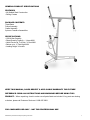
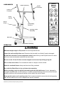
DWHOIST
Drywall Hoist
Assembly & Operating Instructions
READ ALL INSTRUCTIONS AND WARNINGS BEFORE USING THIS PRODUCT.
SAVE THESE INSTRUCTIONS FOR FUTURE REFERENCE.
This manual provides important information on proper operation and maintenance. Every effort has
been made to ensure the accuracy of this manual. We reserve the right to change this product at any
time without prior notice.
STOP!
CONTACT CUSTOMER SERVICE WITH QUESTIONS OR PROBLEMS.
DO NOT RETURN THIS PRODUCT TO THE RETAILER.
If you experience a problem or need parts for this product, visit our website http://www.buffalotools.com
or call our customer help line at 1-888-287-6981, Monday-Friday, 8 AM - 4 PM Central Time. A copy
of the sales receipt is required.
TABLE OF CONTENTS
RECOGNIZE SAFETY SYMBOLS, WORDS AND LABELS ........................................................................ 2
GENERAL PRODUCT SPECIFICATIONS .................................................................................................. 3
FEATURES ................................................................................................................................................. 3
PACKAGE CONTENTS............................................................................................................................... 3
SPECIFICATIONS....................................................................................................................................... 3
IMPORTANT SAFETY RULES .................................................................................................................... 4
OPERATION ............................................................................................................................................... 5
PARTS DIAGRAM ..................................................................................................................................... 11
PARTS LIST .............................................................................................................................................. 12
RECOGNIZE SAFETY SYMBOLS, WORDS AND LABELS
What You Need to Know About Safety Instructions
Warning and Important Safety Instructions appearing in this manual are not meant to cover all possible
conditions and situations that may occur. Common sense, caution and care must be exercised when
assembling or using this product.
Always contact your dealer, distributor, service agent or manufacturer about problems or conditions you
do not understand.
This is a safety alert symbol. It is used to alert you to potential personal injury hazards.
Obey all safety messages that follow this symbol to avoid possible injury or death.
This is a safety alert symbol. It is used to alert you to potential personal injury hazards.
Obey all safety messages that follow this symbol to avoid possible injury or death.
DWHOIST Drywall Hoist Assembly & Operating Instructions
2
GENERAL PRODUCT SPECIFICATIONS
FEATURES
• All Welded Steel Construction
• Rolling Casters
PACKAGE CONTENTS
Tripod Base
Frame Assembly
Cradle Assembly
2-pieces Crossarm Assemblies
SPECIFICATIONS
• 150 Lb Max Capacity
• Sheet Quantity Capacity – 1 piece MAX
• Holds Panels Up To 4 feet x 16 feet MAX
• Raises up to 11 Feet High MAX
• Loading Height 34 Inches
KEEP THIS MANUAL, SALES RECEIPT & APPLICABLE WARRANTY FOR FUTURE
REFERENCE. READ ALL INSTRUCTIONS AND WARNINGS BEFORE USING THIS
PRODUCT. When unpacking, check to make sure all parts listed are included. If any parts are missing
or broken, please call Customer Service at 1-888-287-6981.
FOR CONSUMER USE ONLY – NOT FOR PROFESSIONAL USE
DWHOIST Drywall Hoist Assembly & Operating Instructions
3
IMPORTANT SAFETY RULES
COMMON SENSE AND CAUTION ARE FACTORS WHICH CANNOT BE BUILT INTO ANY PRODUCT.
THESE FACTORS MUST BE SUPPLIED BY THE OPERATOR.
Keep the work area clean and well lit. A cluttered work area may cause accidents.
Never allow children to use this product without responsible adult supervision. When operating this
product, keep children at a safe distance from the work area.
Wear suitable clothing. Do not wear loose clothing or jewelry. They may get caught in moving parts.
Never wear rings with protruding parts. Wear a hat over long hair.
Always wear safety goggles, a hard hat and work gloves when using the product.
When not in use, store product in a secure, dry and safe place. The storage area should be lockable
and out of the reach of children.
Use a product designed for the job being performed. Never use this tool for anything other than its
intended purpose.
Maintain this product with care. This product works best and safest if it is kept clean. Observe the
instructions for maintenance and changing accessories. Keep dry and free of oil and grease.
Stay alert. Do not use this product when impaired by medicine, drugs, or alcohol. Watch what you are
doing and use common sense for your safety.
Before using this tool, check that all safety devices and parts operate smoothly and efficiently.
Make sure that all moving parts are in working order. Do not use the hoist with broken or damaged parts.
For your own safety, use only accessories recommended in this manual.
Service must be performed by qualified repair personnel. Service or maintenance performed by
unqualified personnel could result in a risk or injury.
When servicing a tool, use only identical replacement parts. Use of unauthorized parts or failure to
follow maintenance instructions may create a risk of injury.
DWHOIST Drywall Hoist Assembly & Operating Instructions
4
COMPONENTS
Cradle Assembly
Cradle
Crossarm
Read &
Obey All
Warning
Labels
Cradle
Crossarm
Winch
Handle
Winch
Wheel
Telescoping
Sections
Housing Frame
Assembly
Backstop
Tripod Base Assembly
OPERATION
Maximum weight usage is 150 pounds. Do not lift beyond that load.
Inspect the unit carefully before use. Determine that the cable is not kinked, frayed or damaged.
Drywall Hoist should be at room temperature when in use. Moving a cold Drywall Hoist into a warm
room can create condensation and affect the winch brake.
Do not use the Lift arm if either crossarm support is not secured by locking spring tab.
Use on a flat, level surface. Do not release the load on a slope or uneven surface.
Watch for overhead fixtures. Keep area free when lifting overhead.
Be certain the Brake Drum is dry and clean when operating.
Before operating, check the drywall hoist and inspect the cable before use. A worn, damaged or
improperly installed cable can fail resulting in a sudden and rapid lowering of the hoist and the load and
possibly resulting in serious property damage, serious bodily injury and/or death.
Keep guards in place and in working order. Both crossarms should be secured by the locking spring
tabs, and the slide bar lock is fully engaged when winch is extended.
DWHOIST Drywall Hoist Assembly & Operating Instructions
5
OPERATION (Continued)
Unpack product from package and review contents. Keep all packaging until product has been
reviewed. This product should be inspected prior to use to make certain all parts are intact and safe to
use after assembly.
ASSEMBLY
Keep the work area clean and well lit. A cluttered work area may cause accidents.
Never allow children to use this product without responsible adult supervision. When operating this
product, keep children at a safe distance from the work area.
Wear suitable clothing. Do not wear loose clothing or jewelry. They may get caught in moving parts.
Never wear rings with protruding parts. Wear a hat over long hair.
Always wear safety goggles, a hard hat and work gloves when using the product.
Make sure all parts are available before assembly: Tripod assembly, frame assembly (winch and 4 foot
telescoping lift sections), cradle assembly (without crossarms) and two cradle crossarms.
1. Set up the tripod base on the floor. Press firmly down on the slide yoke ring while you swing the two
forward legs until the yoke ring snaps into the lock hole on the bottom of the slide tube. (Lower the
backstop to prevent rolling.)
2. Place the frame onto the two “V” angles on the tripod base, then lower the frame 1 inch until it is secured
by the angles. Be certain that the frame is press down and held securely by the angles.
3.Attach the handle to the winch wheel. Tighten the nut so that the handle turns freely.
4. To move the winch assembly into its working position, hold the winch wheel and brake arm. Rotate the
winch wheel slightly forward. Lift the breake arm to release the brake.
5. Raise the brake arm. Hold the winch post and brake arm firmly. Place your right hand on top of the
frame. Grip the brake arm to prevent cable backlash, then pull the winch assembly towards you.
Release the brake arm when the winch is fully extended. Swing the Retaining Hook (Figure G) so it doesn’t
secure the telescoping sections.
6. Press the winch assembly slightly toward the frame. This engages the slide bar lock and keeps the
winch extended. BE CERTAIN THE SLIDE BAR LOCK IS ROTATED AS FAR CLOCKWISE AS
POSSIBLE.
DWHOIST Drywall Hoist Assembly & Operating Instructions
6
7. Attach cradle to the frame, by inserting the post into the opening on top of the frame.
8. Attach the cradle to the frame by snapping the tilt latch upward so it hooks over the stud.
9. Slide the tapered plates on the crossarms into the tapered sockets on the cradle.
10. Press each crossarm forward into the socket until the spring tab on the bottom of the crossarm
snaps into place.
Tilt Latch
Tilt Latch
Retaining Hook
Cable Housing
Figure F
Figure F
Figure G
Figure D
Brake Arm
Figure B
Winch Wheel
Figure C
DWHOIST Drywall Hoist Assembly & Operating Instructions
Panel Support Hook
Figure H
Panel Support Hook
Figure H
7
PRODUCT USAGE
Slide the yoke ring to unlatch the two forward legs so the can be rotated out to the lift’s working position or
in to its storage position. A spring-loaded pin snaps into a hole on the bottom of the slide tube, to lock the
legs.
To prevent the base from rolling, move the backstop up or down. (Figure J)
The outriggers extend to support a longer drywall panel.
Figure J
Pull out the lock pin (Figure K) until you can slide the outrigger with your
left hand. The lockpin will engage to lock the outrigger in one of the
three notches: retracted 100%, extended 21 inches or extended 33 inches.
DO NOT LOAD A DRYWALL PANEL IF THE LOCK PINS ARE NOT
ENGAGED IN ONE OF THE THREE POSITIONS.
Figure K
Open the panel support hook on each crossarm to support the drywall panel when it is being loaded.
Always close the support hooks before transporting the lift.
The slide bar lock holds the winch assembly at the fully extended position.
Tilt Latch
To raise the panel or allow the cradle to tilt, pivot the Tilt Latch (Figure F) out and down. To lock the crade
onto the frame without tilting, pivot the latch up to engae the stud on the cradle.
Brake Arm
Spring-loaded brake holds the cradle at whatever height you raise it by cranking the winch wheel. To lower
the cradle, control the backward rotation of the winch by grasping the wheel handle as you carefully raise
the Brake Arm to release the brake. (Figure B)
Winch Wheel, Handle and Post (Figure C)
Cranking the winch coils or uncoils the cable that raises or lowers the cradle. Grasp the post for leverage
when cranking the winch.
Retaining Hook (Figure G)
The retaining hook secures the telescoping sections inside the frame when transporting or storage.
Before Operating
To Load the Drywall
Set the backstop so the lift won’t roll backward. (Figure J)
Swing open the panel support hooks on the two crossarms. Be sure the cradle is turned so the support
hooks are on the opposite side from the winch wheel.
Extend the crossarm outriggers on the cradle as needed to fully support the length of the drywall panel.
Release the tilt latch to tilt the cradle.
Hold the drywall panel with its face paper toward the tilted cradle, and load the panel onto the lift. Set the
panel onto the Support Hooks (H), and lean it against the crossarms.
If installing the panel on a flat ceiling (Figure L), tilt the cradle back up to its level position and lock the tilt
latch. If installing the panel on a side wall or a sloped ceiling (Figure M), leave the cradle tilted.
DWHOIST Drywall Hoist Assembly & Operating Instructions
8
Raise the backstop on the base, and carefully roll the lift close to the position where the panel will be
installed.
To Raise The Panel
Always lower the backstop before raising the panel to a sloped ceiling or side wall.
Hold the post for leverage and crank the winch wheel. The brake is spring-loaded
to automatically hold the cradle at the selected height when you stop cranking.
To Lower The Panel
Hold the wheel handle so you can support the backward rotation of the winch.
Release the brake with your left hand and rotate the wheel SLOWLY backward.
Figure L
To Disassemble
Crank the handle all the way down.
Slide the cradle outriggers until they latch. Close the panel support hooks.
Remove the crossarms by pressing the spring tab on the bottom and sliding
the crossarm out of the socket.
Unlock the cradle tilt latch. Lift the cradle unitl you can remove it from the frame.
Rotate the winch wheel one full rotation forward as shown. This will raise
the inner telescoping section.
Unlock the winch assembly by lifting the slide bar with your left hand. While you
rotate the slide bar lock, turn it clockwise.
Figure M
Hold the slide bar lock in the disengaged position. Press down on the telescoping section in the frame. The
winch assembly will move toward the frame housing.
Hold the slide bar lock in this disengaged position and press down on the telescoping section in the frame
with your left hand. The winch assembly will move toward the frame housing.
Crank the telescoping sections all the way down. Swing up the retainig hook as shown, and crank the
telescoping sections back up slightly until secured by the hook.
Hold the retaining hook in this position with your left hand, and rotate the winch forward with your right
hand.
The winch assembly will fold up against the frame. When the slide bar contacts the frame, tighten the cable
by turning the wheel further (just enough to hold the winch assembly in this position.)
Lift the frame about 1 inch to free it from the tripod base.
Fold the base by pressing down on the slide yoke ring and pivot the forward legs until they lock in the
closed position.
DWHOIST Drywall Hoist Assembly & Operating Instructions
9
MAINTENANCE
Before and after using this tool, check the cable. Occasionally oil the cable sheaves and caster
bearings. Crank up the telescoping sections for access to the internal cable pulley. If the telescoping
sections of the frame don’t operate smoothly, apply household paraffin to the sliding surfaces for
smoother action.
Some chemicals can damage the product. Do not use harsh chemicals such as gasoline, carbon
tetrachloride, paint thinner, etc. to clean this product.
A qualified repair technician must perform any service or repair. Service or maintenance performed
by unqualified personnel could result in injury. Use only identical replacement parts. Use of unauthorized
parts or failure to follow maintenance instructions may create a risk of injury.
Inspect the cable along the full length for kinks, frays or damage. A worn, damaged or improperly installed
cable can fail resulting in a sudden and rapid lowering of the hoist and the load and possibly resulting in
serious property damage, serious bodily injury and/or death.
Store under cover.
ACCESSORIES
Use only accessories that are recommended by the manufacturer for your model. Accessories
that may be suitable for one tool may become hazardous when used on another tool.
Optional Extension Accessory is sold separately. Use it for higher ceilings to increase maximum lift to
15 feet.
For installation, remove the standard telescoping sections. Release the cable tension to loosen the cable
from the mooring tab. Pull cable out through the hole in the winch drum.
Grab the top end of the two telescoping sections and lift them out of the frame housing. Pull the end of the
cable toward the winch wheel to raise the sections.
Remove the sections and cable out of the frame housing.
To install the Extension accessory, feed the crimped end of the accessory cable down into the pocket.
THE CABLE MUST BE ROUTED OVER THE TOP OF THE PULLEY.
Pull the cable through the pocket, then slide the telescoping sections into the frame.
Feed the end of the cable under then around the winch hub, then through the hole into the winch drum.
Secure the crimped end of cable behind the mooring tab inside the drum. (Figure D)
Rotate the winch wheel forward and take up the cable slack.
DWHOIST Drywall Hoist Assembly & Operating Instructions
10
PARTS DIAGRAM
DWHOIST Drywall Hoist Assembly & Operating Instructions
11
PARTS LIST
#
1
2
3
4
5
6
7
8
9
10
11
12
13
14
15
16
17
18
19
20
21
22
23
24
25
26
27
28
29
30
31
32
Name
Crossarm
Cradle
Mounting Head Body
Screw
Hinge Pin
Spring Washer
Washer
Tension Spring
Support Hook
Hook Clamp
Screw
Yoke Pin
Tension Spring
Nut
Yoke Pin Braket
Screw
End Cap
Outrigger
Clip
Tension Spring
Lock Pin
Slide Bar Lock
Nut
Slide Bar
Aircraft Cable, 1/8"
Outer Mast
Rubber Grip
Winch Post
Rivet
Bolt Shaft
Brake Hub
Brake Arm Spring
Qty
#
Name
2
1
1
1
1
2
2
2
2
2
2
1
1
2
1
2
8
2
2
2
2
1
1
1
1
1
1
1
2
1
1
2
33
34
35
36
37
38
39
40
41
42
43
44
45
46
47
48
49
50
51
52
53
54
55
56
57
58
59
60
61
62
63
64
65
Brake Arm
Winch Post Axle
Clip Cap
Bearing
Washer
Nut
Winch Wheel
Handle Nut
Handle
Cable Pulley
Pulley Axle
Split Pin
Center Mast
Top Mast
Rubber Bushing
Washer
Cable Clamp
Nut
Spring Washer
Washer
Caster
Outer Leg
Tie Arm
Pin
Clip
Center Leg
Backstop Tip
Bracket Plate
Nut
Screw
Spring
Slide Yoke Ring
Gasket
Qty
1
1
1
2
1
1
1
1
1
3
3
6
1
1
1
1
1
3
3
3
3
2
2
8
8
1
2
1
2
2
1
1
1
(DWHOIST1204)
DWHOIST Drywall Hoist Assembly & Operating Instructions
12