1
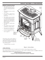
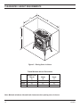
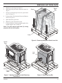
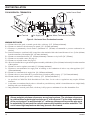
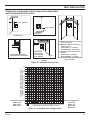
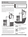
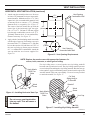
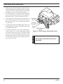
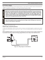
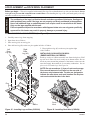
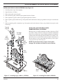
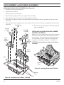
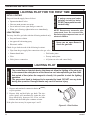
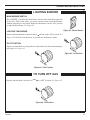
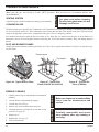
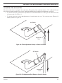
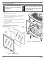
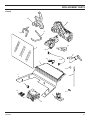
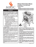
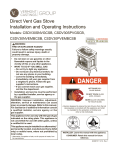
DIRECT VENT GAS
STOVE
CSDV20SNV
CSDV20DNV
CSDV20SLP
CSDV20DLP
MODELS:
CSDV30SNV
CSDV30DNV
CSDV30SLP
CSDV30DLP
CSDV40SNV
CSDV40DNV
CSDV40SLP
CSDV40DLP
INSTALLATION AND OPERATING
INSTRUCTIONS
ON
WARNINGS
OFF
IF THE INFORMATION IN THESE INSTRUCTIONS ARE
NOT FOLLOWED EXACTLY, A FIRE OR EXPLOSION
MAY RESULT CAUSING PROPERTY DAMAGE,
PERSONAL INJURY OR LOSS OF LIFE.
–
Do not store or use gasoline or other flammable
vapors and liquids in the vicinity of this or any
other appliance.
–
WHAT TO DO IF YOU SMELL GAS
• Do not try to light any appliance.
• Do not touch any electrical switch; do not use
any phone in your building.
• Immediately call your gas supplier from a
neighbor's phone. Follow the gas supplier's
instructions.
• If you cannot reach your gas supplier, call the
fire department.
–
Installation and service must be performed
by a qualified installer, service agency or the
gas supplier.
WARNING: Improper installation, adjustment,
alteration, services or maintenance can cause injury or
property damage. Refer to this manual. For assistance
or additional information consult a qualified installer,
service agency or the gas supplier.
This appliance is only for use with the type of gas
indicated on the rating plate. This appliance is
not convertible for use with other gases, unless a
certified kit is used.
This appliance may be installed in an aftermarket*,
permanently located, manufactured home, where not
prohibited by local codes.
*Aftermarket: Completion of sale, not for purpose of resale, from
the manufacturer.
DUE TO HIGH TEMPERATURES, THE
APPLIANCE SHOULD BE LOCATED
OUT OF TRAFFIC AND AWAY FROM
FURNITURE AND DRAPERIES.
CHILDREN AND ADULTS SHOULD
BE ALERTED TO THE HAZARDS OF
HIGH SURFACE TEMPERATURE AND
SHOULD STAY AWAY TO AVOID BURNS
OR CLOTHING IGNITION.
YOUNG CHILDREN SHOULD BE
SUPERVISED WHEN THEY ARE IN THE
SAME ROOM AS THE APPLIANCE.
CLOTHING OR OTHER FLAMMABLE
MATERIAL SHOULD NOT BE PLACED ON
OR NEAR THE APPLIANCE.
KEEP THE ROOM AREA CLEAR AND
FREE FROM COMBUSTIBLE MATERIALS,
GASOLINE, AND OTHER FLAMMABLE
VAPORS AND LIQUIDS.
READ BEFORE INSTALLING. SAVE THESE INSTRUCTIONS
CONTENTS
CONGRATULATIONS!
You have purchased a state-of-the-art gas appliance featuring the Lex-Fire Burn System
available exclusively on Lexington Forge gas appliances.
The Lex-Fire Burn System sets a new standard for flame appearance through innovative log
design, burner technology and ember placement. Each element effecting combustion and
flame appearance was carefully scrutinized and strategically balanced during the design
process to provide a product that was truly
“BORN TO BURN.”
Important Safety Information .......................... 3
Product Features .............................................. 5
Code Approval .................................................. 5
Pre-Installation Information
Installing Above 2000 Feet ............................ 6
Orifice Sizes, Pressures and BTUs ............... 6
Stove Dimensions ......................................... 7
Stove Location .............................................. 8
Clearances ........................................................ 9
Vent Installation .............................................. 12
Installation Precautions ............................... 12
Installation Planning .................................... 13
Installation for Horizontal Termination ......... 14
Installation for Vertical Termination ............. 20
Stove Installation
Check Gas Type.......................................... 24
Installing Gas Piping to Stove Location....... 24
Checking Gas Pressure ................................. 26
Electrical Installation...................................... 27
Electrical Wiring .......................................... 27
Remote Wall Switch .................................... 27
Operating Instructions ................................... 31
What To Do If You Smell Gas ...................... 31
Lighting Pilot for the First Time.................... 32
Lighting Pilot................................................ 32
Lighting Burner ............................................ 33
To Turn Off Gas ........................................... 33
Cleaing and Maintenance .............................. 34
Venting System ........................................... 34
Cleaning Glass ............................................ 34
Pilot and Burner Flames.............................. 34
Firebox Cleaning ......................................... 34
Air Shutter Adjustment .................................. 35
Glass Replacement ........................................ 36
Replacement Parts ......................................... 37
CSDV20 ..................................................... 37
CSDV30 ...................................................... 39
CSDV40 ...................................................... 41
Troubleshooting ............................................. 43
Installation Records ....................................... 44
Mass Residents Only ..................................... 45
Warranty ...........................................Back Cover
Log and Rock Wool Placement ..................... 28
2
58D6056
IMPORTANT SAFETY INFORMATION
WARNING
INSTALLER
Please leave these instructions with the appliance.
OWNER
Please retain these instructions for future reference.
• Read this owner’s manual carefully and completely before trying to assemble, operate,
or service this stove.
• Any change to this stove or its controls can be dangerous.
• Improper installation or use of this stove can cause serious injury or death from fire,
burns, explosions, electrical shock and carbon monoxide poisoning.
This stove is a vented product. This stove must be properly
installed by a qualified service person. The glass door must be
properly seated and sealed. If this unit is not properly installed
by a qualified service person with glass door properly seated
and sealed, combustion leakage can occur.
CARBON MONOXIDE POISONING: Early signs of
carbon monoxide poisoning are similar to the flu with headaches, dizziness and/or nausea. If you have these signs, the
stove may not have been installed properly. Get fresh air at
once! Have the stove inspected and serviced by a qualified
service person. Some people are more affected by carbon
monoxide than others. These include pregnant women, people
with heart or lung disease or anemia, those under the influence
of alcohol, and those at high altitudes.
Propane/LP gas and natural gas are both odorless. An odormaking agent is added to each of these gases. The odor helps
you detect a gas leak. However, the odor added to these gases
can fade. Gas may be present even though no odor exists.
Make certain you read and understand all warnings. Keep
this manual for reference. It is your guide to safe and proper
operation of this stove.
1. This appliance is only for use with the type of gas indicated on the rating plate. This appliance is not convertible
for use with other gases unless a certified kit is used.
2. For propane/LP stove, do not place propane/LP supply
tank(s) inside any structure. Locate propane/LP supply
tank(s) outdoors. To prevent performance problems, do not
use propane/LP fuel tank of less than 100 gal. capacity.
3. If you smell gas
• shut off gas supply.
• do not try to light any appliance.
• do not touch any electrical switch; do not use any
phone in your building .
• immediately call your gas supplier from a neighbor’s
phone. Follow the gas supplier’s instructions.
4.
Never install the stove
• in a recreational vehicle
• where curtains, furniture, clothing, or other flammable
objects are less than 42" from the front, top, or sides
of the stove
• in high traffic areas
• in windy or drafty areas
5. This stove reaches high temperatures. Keep children and
adults away from hot surfaces to avoid burns or clothing
ignition. Stove will remain hot for a time after shutdown.
Allow surfaces to cool before touching.
6. Carefully supervise young children when they are in the
room with stove.
7. Do not modify the burner or stove under any circumstances. Any parts removed for servicing must be replaced
prior to operating stove.
8. Turn stove off and let cool before servicing, installing, or
repairing. Only a qualified service person should install,
service, or repair the stove. Have burner system inspected
annually by a qualified service person.
9. You must keep control compartments, burners, and circulating air passages clean. More frequent cleaning may
be needed due to excessive lint and dust from carpeting,
bedding material, pet hair, etc. Turn off the gas valve and
pilot light before cleaning stove.
10. Have venting system inspected annually by a qualified
service person. If needed, have venting system cleaned
or repaired. See Cleaning and Maintenance, page 34.
11. Keep the area around your stove clear of combustible
materials, gasoline, and other flammable vapor and liquids. Do not run burner system where these are used or
stored. Do not place items such as clothing or decorations
on or around stove.
Continued on page 4
58D6056
3
IMPORTANT SAFETY INFORMATION
13. Never place anything on top of stove.
17. When the appliance is installed directly on carpeting,
tile or other combustible material other than wood flooring, you must set appliance on a metal or wood panel
or hearth pad extending the full width and depth of the
appliance.
14. Do not use any solid fuels (wood, coal, paper, cardboard,
etc.) in this stove. Use only the gas type indicated on
burner system nameplate.
18. Do not use stove if any part has been exposed to or under
water. Immediately call a qualified service person to
arrange for replacement of the unit.
15. This appliance, when installed, must be electrically
grounded in accordance with local codes or in the
absence of local codes, with the National Electrical
Code, ANS/NFPA 70, or the Canadian Electrical Code,
CSA C22.1.
19. Do not operate stove if any log is broken.
Continued from page 3
12. Do not use this stove to cook food or burn paper or other
objects.
16. Do not obstruct the flow of combustion and ventilation
air in any way. Provide adequate clearances around
air openings into the combustion chamber along with
adequate accessibility clearance for servicing and proper
operation.
4
20. Do not use a blower insert, heat exchanger insert, or
other accessory not approved for use with this stove.
21. Do not operate the stove with glass door removed,
cracked, or broken.
ATTENTION MASSACHUSETTS RESIDENTS:
This Lexington Forge product must be installed by a
licensed gas fitter.
58D6056
PRODUCT FEATURES AND CODE APPROVAL
PRODUCT SPECIFICATIONS
•
This appliance has been certified for use with either natural or
propane gas. See appropriate data
plates.
•
This appliance is not for use with
solid fuels.
•
The appliance is approved for
bedroom or bedsitting room
installations.
•
The appliance must be installed
in accordance with local codes if
any. If none exist use the current
installation code. ANSI Z223.1/
NFPA 54 in the USA, CAN/CGA
B149 in Canada.
•
This appliance is mobile home
approved.
•
The appliance must be properly
connected to a venting system.
•
The appliance is not approved for
closet or recessed installations.
•
For alcove installation see “Clearances,” page 10.
Optional
Remote
Receiver
On/Off
Switch
ON
OFF
Hi/Lo
Knob
Pilot
The efficiency rating of this appliance is
a product thermal efficiency rating determined under continuous operating conditions and was determined independently
of any installed system.
Optional
Blower
Door
Ignitor Box
Located Under
Right Front Leg
Thermal Efficiency = up to 80%
CODE APPROVAL
Figure 1 - Cast Iron Stove
Direct Vent type appliances draw all combustion air from outside of the dwelling through the vent pipe.
These appliances have been tested by CSA and found to comply with the established standards for DIRECT VENT GAS
FIREPLACE HEATERS in the USA and Canada as follows:
LISTED VENTED GAS FIREPLACE HEATER
TESTED TO: ANSI Z21.88b-2001/CSA 2.33b-2001 STANDARDS
58D6056
5
PRE-INSTALLATION INFORMATION
INSTALLING ABOVE 2000 FEET
•
In the USA, the appliance must be derated 4% for every 1,000 ft above 2,000 ft elevations.
•
In Canada, these appliances are certified for altitudes of 0 – 2000 ft, and must be de-rated by 10 percent for installations
between 2000 and 4,500 ft. (derate an additional 4% for every 1,000 ft. above 4,500 ft. elevations).
ORIFICE SIZES, PRESSURES AND BTUs
NATURAL GAS
Manifold Press: (W.C.)
3.5"
Maximum Supply Pressure 10.5"
Minimum Supply Pressure
4.5"
Model
Number
CSDV20
PROPANE GAS
Manifold Press: (W.C.)
10"
Maximum Supply Pressure 13"
Minimum Supply Pressure 11"
CSDV30
CSDV40
Gas Type
Natural
Propane
Natural
Propane
Natural
Propane
Max. BTU/Hr.
18,000
19,000
28,000
28,000
33,000
33,000
Min. BTU/Hr.
12,500
15,000
17,000
21,000
26,000
30,000
#43
#54
#35
#51
Front #46, Rear #43
Front #57, Rear 1.45mm
Orifice size
Each stove is equipped with a variable output gas control.
6
58D6056
PRE-INSTALLATION INFORMATION
STOVE DIMENSIONS
A
B
C
DV20
207/8"
231/2"
183/4"
DV30
261/2"
281/2"
21"
DV40
291/2"
301/2"
22"
A
C
B
Figure 2 - External Stove Dimensions
58D6056
7
PRE-INSTALLATION INFORMATION
STOVE LOCATION
Plan for the installation of your stove. This includes determining where the unit is to be installed, the vent configuration to
be used, framing and finishing details, and whether any optional accessories (i.e. blower, wall switch, or remote control)
are desired. Consult your local building code agency to ensure compliance with local codes, including permits and inspections.
The following factors should be taken into consideration:
• This stove should have sufficient access for its safe operation and maintenance.
• Locate a position where the flue system of the stove can be properly installed without damaging the integrity of the
building. e.g. cutting wall or ceiling joist (example: load-bearing framing members).
• When the appliance is installed directly on carpeting, tile or other combustible material other than wood flooring, you
must set appliance on a metal or wood panel extending the full width and depth of the appliance.
• Check stove and flue system clearance requirements.
• Locate the stove where it can be accessed by a gas supply line.
• Locate the stove in a large and open room that is centrally located in the house. This will optimize heat circulation
and comfort.
• The flow of combustion and ventilation air must not be obstructed.
• Minimum clearances to combustibles, side-wall, ceiling, woodwork, and windows must be maintained. See Figure 4,
page 9.
• This stove may be installed along a wall, across a corner, or use an exterior chase. See Figure 3 for suggested locations.
• Location should be out of high traffic areas and away from furniture and
draperies due to heat from appliance.
• Never obstruct the front opening of the
stove.
• Do not install in the vicinity where
gasoline or other flammable liquids may
be stored.
• Vent pipe routing. See Venting section
Cast Iron Stove
found in this manual for allowable venting configurations.
• These units can be installed in a bedroom. See National Fuel Gas Code
ANSI Z233.1/NFPA 54 (current edition), the Uniform Mechanical Code
(current edition), and Local Building
Codes for specific installation requirements.
ON
OFF
NOTE: If this unit is installed in
a mobile home it must be bolted
securely to the floor with leg bolts.
NOTE: Stoves work without any
electrical supply.
Figure 3 - Example of Typical Installations
(see “Clearances,” page 9)
8
58D6056
CLEARANCES
CLEARANCES TO COMBUSTIBLES
WARNING
The dimensions shown in Figures 4 and 5 are minimum clearances to maintain in
installing this heater. Left and right clearances are determined when facing the front
of the heater.
Follow these instructions carefully to ensure safe installation. Failure to follow
instructions exactly can create a fire hazard.
The appliance cannot be installed on a carpet, tile or other combustible material other
than wood flooring. If installed on carpet or vinyl flooring, the appliance shall be installed
on a metal, wood or noncombustible material panel extending full width and depth of
the appliance.
Ceiling
Ceiling
B
Side
Wall
Side
Wall
C
Mantel
A
E
Minimum
36"
in Front
D
Minimum
to Either
Side Wall
F
Minimum
Side View
Front View
F Minimum
D
Minimum
to Either
Side Wall
Floor
G
Floor
G
Wall Installation
Corner Installation
Figure 4 - Minimum Clearance to Walls and Ceiling
Mantel Clearance from
Top of Unit
Corner
Measured
From Top
Corners
Min. Ceiling
from Floor
Max.
Protrusion
Min. Height
Right
Left
Rear
Measured
from Back
A
B
C
D
E
F
G
DV20
72"
12"
22"
4"
4"
1"
½"
DV30
72"
12"
34"
4"
4"
1"
½"
DV40
72"
12"
34"
4"
4"
1"
½"
Product
58D6056
Side, Measured from Top
9
CLEARANCES / HEIGHT REQUIREMENTS
C
B
ON
OFF
A
Figure 5 - Placing Stove in Alcove
Tested Minimum Alcove Dimensions
DV20
DV30
Height From
Hearth
A
52"
64"
Width
B
30"
35"
Depth
C
36"
36"
DV40
64"
35"
36"
Note: Maintain minimum side and back clearances when placing stove in alcove.
10
58D6056
REMOVING UNIT FROM CRATE
1.
Remove two (2) straps. See Figure 6.
2.
Open plastic bag and slide to bottom of unit. See
Figure 7.
3.
Lift up on ash lip and pivot down to open control
door. See Figure 8.
4.
Lift up on front. Pivot bottom of front out. Remove
front. See Figure 8.
5.
Open and remove glass door.
6.
Remove log box from inside of unit.
7.
Lift unit off pallet. Lift unit up high enough to clear
upright supports unit is sitting on.
Plastic
Bag
Straps
ON
F
OF
LO
GS
Note: You will need at least two (2) strong
people to lift unit off of pallet.
Pallet
Figure 6 - Removing Straps and Plastic from Unit
Hearth
Door
LO
Log
Box
LO
GS
GS
RE
MOT
E CO
NT
RE
MOT
RO
E CO
NT
L
RO
L
PI
LO
T
PI
LO
T
OF
F
OF
F
Ash Lip
Control
Door
Figure 7 - Opening Control Door and Removing
Hearth Door
58D6056
Figure 8 - Removing Log Box
11
Read all instructions completely and thoroughly before attempting installation. Failure
to do so could result in serious injury, property damage or loss of life. Operation of
improperly installed and maintained venting system could result in serious injury,
property damage or loss of life.
NOTICE
WARNING
VENT INSTALLATION
Failure to follow these instructions will
void the warranty.
INSTALLATION PRECAUTIONS
Consult local building codes before beginning the installation. The installer must make sure to select the proper vent system
for installation. Before installing vent kit, the installer must read this stove manual and vent kit instructions.
Only a qualified installer/service person should install venting system. The installer must follow these safety rules:
• Wear gloves and safety glasses for protection.
• Use extreme caution when using ladders or when on rooftops.
• Be aware of electrical wiring locations in walls and ceilings.
The following actions will void the warranty on your venting system:
• Installation of any damaged venting component.
• Unauthorized modification of the venting system.
• Installation of any component part not manufactured or approved by Lexington Forge.
WARNING
This stove must be vented to the outside. The venting system must NEVER be attached
to a chimney serving a separate solid fuel burning appliance. Each gas appliance must
use a separate vent system. Do not use common vent systems.
WARNING
• Installation other than permitted by these instructions.
Horizontal sections of this vent system require a minimum clearance of 2" from the top
of the pipe and 1" minimum to the sides and bottom. Vertical sections of this system
require a minimum of 1" clearance to combustible materials on all sides of the pipe. Only
a 1" clearance is required where the vent passes through the nearest vertical wall.
12
58D6056
VENT INSTALLATION
INSTALLATION PLANNING
There are two basic types of direct-vent installation:
• Horizontal Termination
• Vertical Termination
It is important to select the proper length of vent pipe for the type of termination you choose. It is also important to note the
wall thickness.
Select the amount of vertical rise desired. The horizontal run
of venting must have 1/4" rise for every 12" of run towards
the termination.
You may use up to three 90° elbows in this vent configuration.
See Horizontal Termination Configurations on page 14.
WARNING
FOR HORIZONTAL TERMINATION
Never run the vent pipe level or
downward. This may cause excessive
temperatures which could cause a
fire.
FOR VERTICAL TERMINATION
Measure the distance from the stove flue outlet to the ceiling. Add the ceiling thickness, the vertical rise in an attic or second
story, and allow for sufficient vent height above the roof line. You may use one or two 90° elbows in this vent configuration.
See Vertical Termination Configurations on pages 19 and 20.
NOTE: You may use two 45° elbows in place of a 90° elbow. You must follow rise to run ratios when using
45° elbows. The appliance is approved for use with three 90° elbows maximum or a combination of 90°
and 45° elbows up to a maximum of 270°.
For two-story applications, firestops are required at each floor level. If an offset is needed in the attic, additional pipe and
elbows will be required.
You may use a chase with a vent termination with exposed pipe on the exterior of the house. See Installing Vent System in
a Chase below.
It is very important that the venting system maintain its balance between the combustion air intake and the flue gas exhaust.
Certain limitations apply to vent configurations and must be strictly followed.
INSTALLING A VENT SYSTEM IN AN OUTSIDE CHASE
NOTICE
A chase is a vertical boxlike structure built to enclose venting that runs along the outside of a building. A chase is required
for such venting.
Treatment of firestops and construction of the chase may vary from building type to
building type. These instructions are not substitutes for the requirements of local
building codes. You must follow all local building codes.
NOTE: When installing in a chase, you should insulate the chase as you would the outside walls of
your home. This is especially important in cold climates. Minimum clearance between vent pipes and
combustible materials such as insulation is 1".
58D6056
13
VENT INSTALLATION
FOR HORIZONTAL TERMINATION
Inside Corner Detail
G
V
H
A
D
E
C
B
B
G
B
V
L
F
Fixed
Closed
Operable
B
I
Opera- Fixed
ble Closed
V
V
V
B
A
V
Vent Terminal
A
V
A
M
B
V
J
Air Supply Inlet
A
K
A
Area Where Terminals Not Permitted
Figure 9 - Horizontal Vent Termination Location
MINIMUM DISTANCES
A = Clearance above the grade, a veranda, porch, deck, or balcony [*12" (305mm) minimum].
B = Clearance to window or door that may be opened [*12" (305mm) minimum].
C = Clearance to permanently closed window [*minimum 12" (305mm) recommended to prevent condensation on
window]
D = Vertical clearance to ventilated soffit located above the terminal within a horizontal distance of two (2) feet (610mm)
from the centerline of the terminal [18" (457mm) minimum].
E = Clearance to unventilated soffits [12" (305mm) minimum]. Clearance to vinyl soffit [30" (762mm)].
F = Clearance to an outside corner. See page 12.
G = Clearance to an inside corner. See page 12.
H = *Not to be installed above a gas meter/regulator assembly within three (3) feet (914mm) horizontally from the centerline
of the regulator.
I = Clearance to service regulator vent outlet [*3' (914mm) minimum].
J = Clearance to non-mechanical air supply inlet to building or the combustion air inlet to any other appliance [*12"
(305mm)minimum].
K = Clearance to a mechanical air supply inlet [*6' (1829mm) minimum].
L = Clearance above a paved sidewalk or paved driveway located on public property [**7' (2133mm) minimum].
M = Clearance under veranda, porch, deck, or balcony [*12" (305mm) minimum***].
As specified in CAN/CGA B149 Installation Codes. Note: Local codes or regulations may require different
clearances.
** A vent must not terminate directly above a sidewalk or paved driveway, which is located between two single-family
dwellings and serves both dwellings.
*** Only permitted if veranda, porch, deck, or balcony is fully open on a minimum of two sides beneath the floor.
WARNING
*
14
Always maintain minimum clearances around vent systems. The minimum clearances
to combustibles for horizontal vent pipe are 2" at the top and 1" at the sides and bottom
of the vent system. For wall firestops, a 1" minimum clearance all around the pipe must
be maintained. Do not pack the open air spaces with insulation or other materials. This
could cause high temperatures and may present a fire hazard.
58D6056
VENT INSTALLATION
TERMINATION CLEARANCES FOR BUILDINGS WITH COMBUSTIBLE
AND NONCOMBUSTIBLE EXTERIORS
D
C
C
G
G=6" (152mm)
V
V
V
Inside Corner
Outside Corner
H
G
V
V
J
G = Combustible 24"(610mm)
Noncombustible 18"(457mm)
Balcony with No Side Wall
E
F=6" (152mm)
F
Combustible &
Noncombustible
H = 24" (610mm)
J = 20" (508mm)
C = Maximum depth of 48" (1219mm)
for alcove location
D = Minimum width for back wall of
alcove location
Combustible - 38" (965mm)
Noncombustible - 24" (610mm)
E = Clearance from corner in alcove
location
Combustible - 6" (152mm)
Noncombustible - 2" (51mm)
Balcony with Perpendicular
Side Wall
Alcove Location
Figure 10 - Allowable Venting Chart
VERTICAL HEIGHT 40' MAX (12.2m)
(MEASURED FROM STOVE TOP)
40
38
36
34
32
30
28
26
24
22
20
18
16
14
12
10
8
6
4
Actual Stove Height 2
0
DV20 = 231/2"
DV30 = 283/2"
DV40 = 301/2"
Use Restrictor
Disk Above
Dotted
Line
NOTE: Any vent configurations within
the shaded areas are acceptable.
Minimum Height from
Stove Top
1 2 3 4 5 6 7 8 9 10 11 12 13 14 15 16 17 18 19 20
DV20 = 18"
HORIZONTAL RUN 20' MAX (6.1m)
DV30 = 30"
DV40 = 30"
Minimum Height from Stove Top 18"
Figure 11 - Acceptable Vent Configurations
58D6056
15
VENT INSTALLATION
1. Determine the route your horizontal venting will take.
Note: The location of the horizontal vent termination
on the exterior wall must meet all local and national
building codes.
Snorkel terminations are available for terminations requiring a vertical rise on the exterior of the building. See Figures
12 and 13. Follow the same installation procedures used for
standard horizontal terminations. If installing the snorkel
termination below grade (basement applications), you must
provide proper drainage to prevent water from entering the
snorkel termination. See Figure 13. Do not back fill around
the snorkel termination.
WARNING
INSTALLATION FOR HORIZONTAL TERMINATION
Do not recess vent terminal into a wall
or siding.
Snorkel
Snorkel
12"
Minimum
Adequate
Drainage
12"
Minimum
Figure 13 - Snorkel Termination with Drainage Pipe
Figure 12 - Snorkel Termination
2. Rigid vent pipes and fittings have special twist-lock connections. Assemble the desired combination of pipe and
elbows to the appliance adaptor with pipe seams oriented
towards the wall or floor.
Twist-lock Procedure: The female ends of the pipes and
fittings have three locking lugs (indentations). These lugs
will slide straight into matching slots on the male end of
adjacent pipes and fittings. Push the pipe sections together
and twist one section clockwise approximately one-quarter
turn until the sections are fully locked. See Figure 14.
Female
Locking Lugs
Note: Horizontal runs of vent
must be supported every (3)
three feet (914mm). Use wall
straps for this purpose.
Male Slots
Figure 14 - Rigid Vent Pipe
Connections
Continued
16
58D6056
VENT INSTALLATION
HORIZONTAL VENT INSTALLATION (continued)
3. Attach vent pipe assembly to the stove. Set stove
in front of its permanent location to insure minimum clearances. Mark the wall for a 91/2" (241)
square hole (for noncombustible material such
as masonry block or concrete, a 71/2" [190mm]
diameter hole is acceptable). See Figure 15.
The center of the hole should line up with the
center line of the horizontal rigid vent pipe.
Cut a 91/2"x91/2" (241mm X 241mm) square
hole through combustible exterior wall (71/2"
[190mm] diameter hole if noncombustible).
Frame as necessary. See Figure 15.
4. Apply a bead of non-hardening mastic around the
outside edge of vent cap. Position the vent cap in
the center of the 71/2" (190mm) or 91/2" (241mm)
hole on the exterior wall with the word “UP” on
the vent cap facing up. Insure proper clearance
of 1" to combustibles is maintained. Attach the
vent cap with four wood screws supplied. See
Figure 16.
Vent Opening
Combustible Wall
91/2"
(241mm)
1
9 /2"
(241mm)
71/2"
(190mm)
Vent Opening
Noncombustible Wall
Figure 15 - Vent Opening Requirements
NOTE: Replace the wood screws with appropriate fasteners for
stucco, brick, concrete, or other types of siding.
Apply Mastic
to All Four
Sides
For vinyl siding, stucco, or wood exterior use vinyl siding standoffs
between vent cap and exterior wall. The vinyl siding standoff prevents
excessive heat from melting the vinyl siding material. Bolt the vent cap
to the standoff. Apply non-hardening mastic around outside edge of the
standoff instead of the vent cap assembly. Use wood screws provided
to attach the standoff. See Figure 17.
Cut Vinyl
Siding Away to
Fit Standoff
T
HO
Wood
Screw
Standoff
Wood
Screw
Vent Cap
WARNING
Figure 16 - Installing Horizontal Vent Cap
Do not recess vent termination
into any wall. This will cause a
fire hazard.
Apply Mastic
to All Four
Sides
Vent Cap
T
HO
Nut
Bolt
Figure 17 - Installing Vinyl Siding Standoff
Continued
58D6056
17
VENT INSTALLATION
HORIZONTAL VENT INSTALLATION (continued)
Interior Wall
Surface
5. Slide the wall thimble over the vent pipe before connecting
the horizontal run to the vent cap. See Figure 18.
6. Carefully move the stove with vent assembly attached toward
the wall and insert the vent pipe into the horizontal termination. The pipe overlap should be a minimum of 11/4" (mm).
Apply silicone to the outer pipe connection. Fasten all vent
connections with screws provided.
7. Slide the wall thimble against the interior wall surface and
attach with srews. See Figure 18.
Decorative
Wall
Thimble
Vent Cap
(Horizontal
Termination)
Horizontal
Vent Pipe
Figure 18 - Connecting Vent Cap with
Horizontal Vent Pipe
Screw
HORIZONTAL TERMINATION CONFIGURATION EXAMPLES
Figures 19 through 21 show different configurations for venting and horizontal termination. Each figure includes a chart
with an example of horizontal maximum and vertical minimum dimensions taken from the chart on page 15.
Note: The horizontal run controls the minimum vertical height (i.e. the longer the horizontal run, the
higher the termination will be).
Follow the chart on page 15. All horizontal terminations require a 1/4" rise per 12" of horizontal run.
NOTE: Add 1/4" rise per 12" horizontal length of pipe.
NOTE: This configuration is for use with corner
installation also.
Maximum
Horizontal (H)
Vertical
Minimum
CSDV20 (V)
Vertical
Minimum
CSDV30 (V)
Vertical
Minimum
CSDV40 (V)
2'
41.50"
52.50"
54.50"
20'
95.25"
98.75"
102.25"
V
HO
T
H
Table 2 - Horizontal Venting
Figure 19 - Horizontal Termination
Configuration for Rigid Venting Using
One 90° Elbow
18
58D6056
VENT INSTALLATION
VENTING WITH TWO 90° ELBOWS
H1
NOTE: Add 1/4" rise per 12"
horizontal length of pipe.
Maximum
Horizontal (H)
Vertical
Minimum
CSDV20 (V)
Vertical
Minimum
CSDV30 (V)
H
Vertical
Minimum
CSDV40 (V)
2'
41.50"
52.50"
54.50"
20'
95.25"
98.75"
102.25"
V
Table 2 - Venting with Two 90° Elbows
Figure 20 - Horizontal Termination
Configuration for Rigid Venting Using
Two 90° Elbows
VENTING WITH THREE 90° ELBOWS
NOTE: Add 1/4" rise per 12" horizontal
length of pipe.
H1
V1
HO
T
Maximum
Horizontal (H)
Vertical (V+V1)
Minimum
CSDV20 (V)
Vertical (V+V1)
Minimum
CSDV30 (V)
Vertical (V+V1)
Minimum
CSDV40 (V)
2'
41.50"
52.50"
54.50"
20'
95.25"
98.75"
102.25"
V
H
Table 3 - Venting with Three 90° Elbows
Figure 21 - Horizontal Termination Configuration
for Rigid Venting Using Three 90° Elbows with
Termination at 90° with Stove
58D6056
19
VENT INSTALLATION
INSTALLATION FOR VERTICAL TERMINATION
1. Determine the route your vertical venting will take. If ceiling joist,
roof rafters or other framing will obstruct the venting system,
consider an offset. See Figure 22 to avoid cutting load bearing
members.
NOTE: Pay special attention to these installation instructions
for required clearances (air space) to combustibles when
passing through ceilings, walls, roofs, enclosures, attic
rafters, etc. Do not pack air spaces with insulation. Also
note maximum vertical rise of the venting system and any
maximum horizontal offset limitations. Offsets must fall
within the parameters shows in Figure 10 on page 15.
Roof
Flashing
Wall
Strap
45° Elbows
2. Set stove in desired location. Drop a plumb line down from the
ceiling to the position of the burner system exit flue. Mark the
center point where the vent will penetrate the ceiling. Drill a small
locating hole a this point.
Drop a plumb line from the inside of the roof to the locating hole
in the ceiling. Mark the center point where the vent will penetrate
the roof. Drill a small locating hole at this point.
FLAT CEILING INSTALLATION
1. Cut a 91/2" (241mm) square hole in the ceiling using the locating
hole as a center point The opening should be framed to 91/2"x91/2"
(241mm x 241mm) inside dimensions as shown in Figure 24
using framing lumber the same size as the ceiling joist. If the area
above the ceiling is an insulated ceiling or a room, nail firestop
from the top side. This prevents loose insulation from falling into
the required clearance space. See Figure 23. Otherwise, install
firestop below the framed hole. The firestop should be installed
with no less than three nails per side. See Figure 24.
2. Assemble the desired lengths of pipe and elbows necessary to
reach from the burner system flue up through the firestop. Be sure
pipe and elbow connections are fully twist-locked. See Figure
14, page 16.
3. Cut a hole in the roof using the locating hole as a center point.
(Cover any exposed open vent pipes before cutting hole in roof).
The 91/2"x91/2" (241mm x 241mm) hole must be measured on the
horizontal. Actual length may be larger depending on the pitch of
the roof. There must be a 1" minimum clearance from the vent
pipe to combustible materials. Frame the opening as shown in
Figure 15 on page 17.
Ceiling Firstop
Figure 22 - Offset with Wall Strap and 45°
Elbows
Nails
Firestop
Figure 23 - If area above is a room, install
firestop above framed hole as shown
1 2"
9/
9 1/
2
"
Nails
Firestop
Figure 24 - If area above is not a room, install
firestop below framed hole as shown
Continued on next page
20
58D6056
VENT INSTALLATION
4. Connect a section of pipe and extend up through the hole.
NOTE: If an offset is needed to avoid obstructions, you must support the vent pipe every three (3) feet.
Use wall straps for this purpose. See Figure 22, page 20. Whenever possible, use 45° elbows instead of
90° elbows. The 45° elbow offers less restriction to the flow of the flue gases and intake air.
5. Place the flashing over the pipe section(s) extending through the roof. Secure the base of the flashing to the roof and
framing with roofing nails. Be sure roofing material overlaps the top edge of the flashing as shown in Figure 22, page
20. There must be a 1" clearance from the vent pipe to combustible materials.
6. Continue to add pipe sections until the height of the vent cap meets the minimum building code requirements.
NOTE: You must increase vent height for steep roof pitches. Nearby trees, adjoining roof lines, steep
pitched roofs, and other similar factors may cause poor draft or down-drafting in high winds. Increasing
the vent height may solve this problem.
NOTE: If the vent pipe passes through any occupied areas above the first floor, including storage spaces
and closets, you must enclose pipe. You may frame and sheetrock the enclosure with standard construction
material. Make sure to meet the minimum allowable clearances to combustibles. Do not fill any of the
required air spaces with insulation.
CATHEDRAL CEILING INSTALLATION
Level
IMPORTANT: Review all information on previous
page before planning this installation. Cathedral
ceiling installations can be very tricky.
2" Minimum
Below
Finished
Ceiling
1. Remove shingles or other roof covering as necessary to
cut the rectangular hole for the support box. Mark the
outline of the cathedral ceiling support box on the roof
sheathing using the locating hole as a center point.
2. Cut the hole 1/8" larger than the support box outline. See
Figure 25.
3. Lower the support box through the hole in the roof until
the bottom of the box extends at least 2" ( mm) below
the ceiling. See Figure 25. Align the support box vertically and horizontally using a level. Temporarily tack the
support box in place through the inside walls and into the
roof sheeting.
4. Using tin snips, cut the support box from the top corners
down to the roofline and fold the resulting flaps over the
roof sheeting. See Figure 26. Apply a bead of non-hardening mastic around the top edges of the support box to
make a seal between the box and the roof. Nail in place
with roofing nails. Remove any combustible material that
might be inside the support box.
5. Complete the cathedral ceiling installation by following
the same procedures outlines in steps 2 through 6 for Flat
Ceiling Installation, page 20 and above.
Cathedral
Ceiling
Support Box
Cut Hole 1/8"
Larger than
Support Box when
Projected onto
Roofline.
Figure 25 - Cathedral Ceiling Support Box
Installation
Apply Non-hardening
Mastic Under all Edges
of Support Box before
Nailing
Figure 26 - Installed Cathedral Ceiling
Support Box
58D6056
21
VENT INSTALLATION
VERTICAL TERMINATION CONFIGURATIONS
Figures 27 through 30 on pages 22 and 23 show four different configurations for vertical termination.
IMPORTANT: Install restrictor as indicated on chart (Figure 11) on page 15.
NOTE: Install restrictor into
4" collar of stove or first vent
section as shown.
Maximum
Horizontal (H)
Vertical
Minimum
CSDV20 (V)
Vertical
Minimum
CSDV30 (V)
Vertical
Minimum
CSDV40 (V)
2'
41.50"
52.50"
54.50"
20'
95.25"
98.75"
102.25"
Table 5 - Venting with Two 90° Elbows
H
V
NOTE: Install restrictor into 4"
collar of stove or first vent secton
as shown.
H
Figure 27 - Vertical Rigid Venting
Configuration Using Two 90° Elbows
Maximum
Horizontal
(H)
V
H1
Vertical
Vertical
Vertical
Minimum
Minimum
Minimum
CSDV20 (V) CSDV30 (V) CSDV40 (V)
2'
41.50"
52.50"
54.50"
20'
95.25"
98.75"
102.25"
Table 6 - Venting with Three 90° Elbows
Figure 28 - Vertical Rigid Venting Configuration Using Three
90° Elbows with Two Horizontal Runs
22
58D6056
VENT INSTALLATION
H
Maximum
Horizontal
(H)
Vertical
(V+V1)
Minimum
CSDV20 (V)
Vertical
(V+V1)
Minimum
CSDV30 (V)
Vertical
(V+V1)
Minimum
CSDV40 (V)
2'
41.25"
44.75"
48.75"
20'
95.25"
98.75"
102.25"
Table 7 - Venting with Two 90° Elbows
NOTE:
Vertical (V) + Vertical (V1) = 20' Maximum
V1
V
NOTE: Install restrictor into 4"
collar of stove or front vent section
as shown.
V
Vertical Venting
V = 40' maximum
Figure 30 - Vertical Rigid
Venting Configuration
with No Horizontal run
Figure 29 - Vertical Rigid Venting
Configuration Using Two 90° Elbows
SIMPSON DURA-VENT GS 4" X 65/8" (BLACK PIPE)
NUMBER
902B
903B
904B
906B
907B
908B
911B
940
941
943
58D6056
DESCRIPTION
65/8" x 48" Pipe
65/8" x 36" Pipe
65/8" x 24" Pipe
65/8" x 12" Pipe
65/8" x 9" Pipe
65/8" x 6" Pipe
65/8" Adjustable (11" - 145/8" Pipe)
Wall Thimble
Cathedral Ceiling Support Box
Roof Flashing 0/12-6/12
NUMBER
943S
945B
950
953
963
981
984
988
990B
991
DESCRIPTION
Roof Flashing 7/12-12/12
65/8" x 45° Elbow
Vinyl siding Standoff
Storm Collar
Ceiling Firestop
36" Snorkel Termination
Horizontal Termination Vent Cap
Wall Strap
65/8"" x 90° Elbow
Vertical High Wind Termination
23
STOVE INSTALLATION
CHECK GAS TYPE
Use proper gas type for the burner system you are installing. If you have conflicting gas type, do not install burner system.
See dealer where you purchased the stove and burner system for proper burner system according to your gas type.
CAUTION
WARNING
INSTALLING GAS PIPING TO STOVE / BURNER SYSTEM LOCATION
A qualified installer or service person
must connect appliance to gas supply.
Follow all local codes.
For propane/LP units, never connect stove directly to the propane/LP supply. This
burner system requires an external regulator (not supplied). Install the external regulator
between the burner system and propane/LP supply.
INSTALLATION ITEMS NEEDED
Before installing stove and burner system, make sure you have the items listed below.
•
•
•
•
External regulator (supplied by installer) • Piping (check local codes)
• Sealant (resistant to propane/LP gas)
Equipment shutoff valve*
• Test gauge connection*
• Sediment trap
Tee joint
• Pipe wrench
approved flexible gas line with gas connector (if allowed by local codes — not provided)
* A CSA design-certified equipment shutoff valve with 1/8" NPT tap is an acceptable alternative to test gauge connection.
Purchase the CSA design-certified equipment shutoff valve from your dealer.
For propane/LP connections only, the installer must supply an external regulator. The external regulator will reduce incoming
gas pressure. You must reduce incoming gas pressure to between 11 and 13 inches of water. If you do not reduce incoming
gas pressure, burner system regulator damage could occur. Install external regulator with the vent pointing down as shown
in Figure 31. Pointing the vent down protects it from freezing rain or sleet.
100 gal. (min)
Propane/LP
Supply Tank
CAUTION
External
Regulator
Vent
Pointing
Down
Figure 31 - External Regulator with Vent Pointing
Down (Propane/LP Only)
24
Use only new black iron or steel pipe.
Internally tinned copper or copper
tubing can be used per National Fuel
Code, section 2.6.3, providing gas
meets hydrogen sulfide limits, and
where permitted by local codes. Gas
piping system must be sized to provide
minimum inlet pressure (listed on
data plate) at the maximum flow rate
(BTU/hr). Undue pressure loss will
occur if the pipe is too small.
When using copper of flex connectors use only fittings
approved for gas connections. The gas control inlet is
3/8" NPT.
58D6056
Only persons licensed to work with
gas piping may make the necessary
gas connections to this appliance.
CAUTION
WARNING
STOVE INSTALLATION
A manual shutoff valve must be installed
upstream of the appliance. Union tee
and plugged 1/8" NPT pressure tapping
point should be installed upstream of
the appliance. See Figure 32.
NOTE : The gas line connection may be made using 1/2" rigid tubing or an approved flex connector. Since
some municipalities have additional local codes it is always best to consult your local authorities and
the current edition of the National Fuel Gas Code ANSI.Z223.1, NFPA54. In Canada CAN/CGA-B149 (1 or
2) Installation Code.
A listed manual shutoff valve must be installed upstream of the appliance. Union tee and plugged 1/8" NPT pressure tapping
point should be installed upstream of the appliance. See Figure 32.
Check your building codes for any special requirements for
locating equipment shutoff valve to stoves.
Apply pipe joint sealant lightly to make threads. This will
prevent excess sealant from going into pipe. Excess sealant in
pipe could result in clogged burner system valves.
CAUTION
IMPORTANT: Install main gas valve (equipment shutoff valve) in an accessible location. The main gas valve is
for turning on or shutting off the gas to the stove.
Use pipe joint sealant that is resistant
to liquid petroleum (LP) gas.
We recommend that you install a sediment trap/drip leg in supply line as shown in Figure 32. Locate sediment trap/drip
leg where it is within reach for cleaning. Install in piping system between fuel supply and burner system. Locate sediment
trap/drip leg where trapped matter is not likely to freeze. A sediment trap traps moisture and contaminants. This keeps them
from going into the burner system gas controls. If sediment trap/drip leg is not installed or is installed wrong, burner system
may not run properly.
CSA Design-Certified Equipment
Shutoff Valve with 1/8" NPT Tap*
Approved Flexible
Gas Line
Sediment Trap/Drip Leg
Tee Joint
Pipe Nipple
Cap
3"
Mi
nim
um
Natural Gas
From Gas Meter
(5" W.C. to 10.5" W.C. Pressure)
Propane/LP
From External Regulator
(11" W.C. to 13" W.C. Pressure)
Figure 32 - Gas Connection
58D6056
25
CHECKING GAS PRESSURE
Check gas type. The gas supply must be the same as
stated on the appliance’s rating decal. If the gas supply
is different from the fireplace, STOP! Do not install
the appliance. Contact your dealer immediately.
2.
To ease installation, a 30" (mm) flex line with manual
shut-off valve has been provided with on this appliance.
Install and attach 1/2" gas line onto shut-off valve.
3.
After completing gas line connection, purge air from
gas line and test all gas joints from the gas meter to
the fireplace for leaks. Use a soap and water solution
or a gas sniffer.
4. To adjust flame height, turn HI/LO knob to HI to get
maximum pressure to burner. Turn HI/LO knob to LO
to get minimum pressure.
5.
26
To check gas pressures at valve, turn captured screw
counter clockwise 2 or 3 turns and then place tubing
to pressure gauge over test point. Turn unit to high.
See Figure 33. After taking pressure reading, be sure
and turn captured screw clockwise firmly to reseal. Do
not over torque. Check test points for gas leaks with a
soap and water solution.
Pressure
Test “IN”
Pressure
Test “OUT”
HI/LO
Knob
Pilot Adjustment
Screw
Figure 33 - Gas Pressure Check at Gas Valve
WARNING
1.
Do not use open flame to check for
gas leaks.
58D6056
ELECTRICAL INSTALLATION
ELECTRICAL WIRING
This stove will work without any electrical supply. Electricity is only needed if you install a remote wall mounted switch.
WARNING
Electrical connections should only be performed by a qualified, licensed electrician.
Main power must be off when connecting to main electrical power supply or performing
service. All wiring shall be in compliance with all local, city, and state codes. The
appliance, when installed, must be electrically grounded in accordance with local codes,
or in the absence of local codes, with the National Electrical Code ANSI/ NFPA 70 (latest
edition) and Canadian Electrical Code, CSA C22.1.
CAUTION
NOTE: If installed in mobile home, stove must be bolted securely to floor.
Label all wires before disconnecting when servicing controls. Wiring errors can cause
improper and dangerous operation.
Verify proper operation after servicing.
REMOTE WALL MOUNTED SWITCH
A remote wall switch and up to fifteen (15) feet of 18 Ga. wire may be used with this appliance. Attach the wall switch in
a junction box at the desired location on the wall. See Figure 34. Do not extend beyond the wall switch wire length provided.
NOTE: Extended lengths of wire may cause the fireplace not to function properly. Longer length of wire
is permitted if the wire is made out of larger gauge (diameter) wire. Always check with local code.
OPTIONAL REMOTE
WALL SWITCH
ON
HI
OFF
ON
OFF
PILOT
LO
TH
TP
TH/TP
Figure 34 - Wiring Diagram for Wall Switch
58D6056
27
LOG PLACEMENT AND ROCK WOOL PLACEMENT
WARNING
Before you begin — This unit is supplied with ceramic fiber logs. Do not handle these logs with your bare hands. Always
wear gloves to prevent skin irritation from ceramic fibers. After handling the logs, wash your hands gently with soap
and water to remove any traces of fibers.
The positioning of the logs is critical to the safe and clean operation of this heater. Sooting and
other problems may result if the logs are not properly and firmly positioned in the appliance.
Never add additional logs or embellishments such as pine cones or vermiculite to the heater.
Only use the logs supplied with the unit.
Failure to position the parts in accordance with diagrams below or to use only parts specifically
approved for this heater may result in property damage or personal injury.
INSTALLING CSDV20 LOGS IN FIREBOX (See Figure 35)
1. Carefully remove logs from wrapping.
2. Open front door of firebox.
3. Place rear log (#1) on rear log pin.
4. Place left base log (#2) on the two pins against left side of firebox.
Left
Base
Log (#2)
5. Place right base log (#3) on the two pins against right
side of firebox.
Right
Base
Log (#3)
INSTALLING LOGS AND ROCK WOOL
(EMBER MATERIAL) IN FIREBOX
Break up rock wool (ember material) into dime-sized pieces. Fluff
up rock wool. Place rock wool evenly across burner surface. Do not
block any areas around the perimeter of the burner, as these are the
areas that supply the needed air for secondary combustion. Do not
place rock wool under logs. See Figure 36.
Rear
Log
NOTE: Do not exceed one (1) layer of rock wool overage.
Place a small amount of rock wool on the rear side of
the burner only between tabs. The tabs are designed to
indicate the area where rock wool location. Do not place
rock wool outside the tabs in the back.
Pins
RE
MO
TE
CO
NT
RE
RO
L
MO
TE
CO
NT
RO
L
PIL
OT
PIL
OT
OFF
Pins
Figure 35 - Installing Logs on Base (CSDV20)
28
Rock
Wool
OF
F
Figure 36 - Installing Rock Wool (CSDV20)
58D6056
LOG PLACEMENT AND ROCK WOOL PLACEMENT
INSTALLING CSDV30 LOGS IN FIREBOX (See Figure 37)
1. Carefully remove logs from wrapping.
2. Open front door of firebox.
3. Place rear log (#1) on rear log pin.
4. Place left base log (#2) on the two pins against left side of firebox.
5. Place right base log (#3) on the two pins against right side of firebox.
6. Place top left log (#4) on left base log. Line up the notch in the bottom of the top log with the locator pins on the bottom
log.
7. Place top right log (#5) on right base log. Line up the notch in the bottom of the top log with the locator pins on the
bottom log.
Top Left
Log (#4)
INSTALLING LOGS AND ROCK WOOL
(EMBER MATERIAL) IN FIREBOX
Break up rock wool (ember material) into dime-sized pieces. Fluff
up rock wool. Place rock wool evenly across the front of the burner
surface. Do not block any areas around the perimeter of the burner,
as these are the areas that supply the needed air for secondary combustion. Do not cover the screen on the rear half of the burner as
this area allows for air to enter under the front logs. Do not place
rock wool under logs. See Figure 38.
Top Right
Log (#5)
Left
Base
Log (#2)
Right
Base Log
(#3)
NOTE: Do not exceed one (1) layer of rock wool
overage. Do not place rock wool on rear of burner.
Rear
Log (#1)
Pins
RE
RE
MO
TE
C
MO
TE
CO
NT
RO
L
ON
TR
O
L
PIL
OT
PIL
OT
OF
F
Pins
Figure 37 - Installing Logs on Base (CSDV30)
58D6056
Rock
Wool
OF
F
Figure 38 - Installing Rock Wool (CSDV30)
29
LOG PLACEMENT AND ROCK WOOL PLACEMENT
INSTALLING CSDV40 LOGS IN FIREBOX (See Figure 39)
1. Carefully remove logs from wrapping.
2. Open front door of firebox.
3. Place rear log (#1) on rear log pins.
4. Place left base log (#2) on the two pins against left side of firebox.
5. Place right base log (#3) on the two pins against right side of firebox.
6. Place top left log (#4) on left base log. Line up the notch in the bottom of the top log with the locator pins on the
bottom log.
7. Place top right log (#5) on right base log. Line up the notch in the bottom of the top log with the locator pins on the
bottom log.
Top Mid Log
8. Rest one end top mid log (#6) on left base log and the
(#6)
other on front burner.
Top Left
Top Right
Log (#4)
INSTALLING LOGS AND ROCK WOOL (EMBER
Log (#5)
MATERIAL) IN FIREBOX
Break up rock wool (ember material) into dime-sized pieces.
Fluff up rock wool. Place rock wool evenly across both
burner surfaces. Do not block any areas around the perimeter of the burner, as these are the areas that supply the
needed air for secondary combustion. See Figure 40.
Left
Base
Log (#2)
Right
Base Log
NOTE: Do not exceed one (1) layer of rock wool
(#3)
coverage.
Rear
Log (#1)
Pins
RE
MO
TE
CO
NT
RO
L
PILO
T
Rock
Wool
RE
MO
TE
C
OFF
Figure 40 - Installing Rock Wool (CSDV40)
ON
TRO
L
PILO
T
OFF
Rear Log
Pins
Pins
Figure 39 - Installing Logs on Base (CSDV40)
30
58D6056
OPERATING INSTRUCTIONS
WARNING
FOR YOUR SAFETY READ BEFORE LIGHTING
If you do not follow these instruction
exactly, a fire or explosion may result
causing property damage, personal
injury or loss of life.
A. This appliance is equipped with an pilot which must be lit by hand while following these
instructions exactly.
B. BEFORE OPERATING smell all around the appliance area for gas. Be sure to smell next to the floor
because some gas is heavier than air and will settle on the floor.
WHAT TO DO IF YOU SMELL GAS:
• Turn off all gas to the appliance.
• Open windows.
• Do not attempt to light any appliance.
• Do not touch any electric switch; do not use any phone in your building.
• Immediately call your gas supplier from a neighbor's phone. Follow the gas supplier's instructions.
• If you cannot reach your gas supplier, call the fire department.
C. Use only your hand to push in, or turn the gas control knob. Never use tools. If the knob will not push in
or turn by hand, don't try to repair it. Call a qualified service technician. Force or attempted repair may
result in a fire or explosion.
D. Do not use this appliance if any part of it has been under water. Immediately call a qualified service technician to inspect the appliance and to replace any part of the control system and any gas control that has
been under water.
Continued on next page
58D6056
31
OPERATING INSTRUCTIONS
T
LIGHTING PILOT FOR THE FIRST TIME
WARNING
INITIAL LIGHTING
Purge air from the supply line as follows:
• Unscrew main pressure test point.
• Leave inlet test screw open until gas comes in.
• When gas is flowing, tighten inlet screw immediately.
LEAK TESTING
You may check for gas leaks with the following methods only:
• Soap and water solution
• An approved leak testing spray
• Electronic sniffer
Check for gas leaks in each of the following locations:
• Pipe from the gas supply line connection to the gas valve
NOTE: Remove any excessive pipe
compound from the connections.
Excessive pipe compound can set off
electronic sniffers.
WARNING
• Open main shutoff valve.
If using a soap and water
solution to test for leaks,
DO NOT spray solution onto
control body.
Never use an open flame to
check for gas leak.
• Burner thread inlet
• Field made joints
• Pilot
• Factory made joints
• Each joint or connection
• All joints on valve and control body
WARNING
LIGHTING PILOT
The control has an interlock device that does not allow the lighting of the stove up
to the moment the safety device of the flame has not interrupted the gas flow. After
that period of time (when the magnet is closed), it is possible to start the lighting
operation.
The gas control knob is designed to be operated by hand. DO NOT use any tools
during this operation. Damaged knobs may result in serious injury.
1. Depress and turn knob counterclockwise
to pilot position.
If the pilot does not stay lit, repeat steps 1 and 2.
PILOT
F
OF
2. Depress fully and hold pilot gas knob. The electronic ignitor will automatically ignite the pilot.
Keep knob fully depressed for a few seconds.
Release and check that pilot continues to burn.
ON
PIL
OT
Figure 41 - Pilot Position
32
58D6056
OPERATING INSTRUCTIONS
T
LIGHTING BURNER
MAIN BURNER SWITCH
The “ON/OFF” switch for the main burner can be found on the back right side
of the stove. This switch allows you to turn on and to turn off the main burner
without using the gas valve knob. Make sure the button is in the “ON” position
to light the main burner. See Figure 42.
ON
F
OF
Figure 42 - Burner Switch
LIGHTING THE BURNER
Depress and turn the knob counterclockwise
to the “ON” position. See
Figure 43. It will take less than four (4) seconds for the burner to ignite.
ON
PILOT POSITION
OFF
PIL
O
PIL T
Depress and turn knob to pilot position to keep burner off while maintaining the
pilot light. See Figure 44.
OT
Figure 43 - On Position
F
PILOT
ON
OF
PIL
OT
Figure 44 - Pilot Position
TO TURN OFF GAS
to “OFF” position. See Figure 45.
PIL
O
T
OFF
Depress and turn knob clockwise
ON
PIL
OT
Figure 45 - Off Position
58D6056
33
CLEANING AND MAINTENANCE
VENTING SYSTEM
A qualified agency should examine the venting system annually.
CLEANING GLASS
CAUTION
Make sure the gas valve knob is in the “OFF” position. Wait at least five (5) minutes before start ing maintenance.
Let glass cool before cleaning.
Do not clean glass when it is hot.
Damage could occur.
Clean the ceramic glass periodically. Condensation will sometimes form on the glass during a cold startup. This is normal
for all gas fireplaces and stoves. This condensation often attracts dust and lint to the surface of the glass. The initial paint
curing of the appliance can also leave a slight film on the glass. This is a temporary problem.
Your should clean the glass after the first two weeks of use. After that, you should clean the glass no more than two or
three times a season. Use a mild glass cleaner to clean the door. Do not use abrasive cleaners. They will damage the glass
surface.
PILOT AND BURNER FLAMES
Visually check pilot and burner flames periodically. See Figure 46 for typical burner flame. See Figures 45 and 46 for typical pilot flame.
Thermocouple
Thermopile
REM
OT
E
CO
NT
RO
L
PIL
OT
OFF
Figure 46 - Typical Burner Flame
Figure 47 - Typical Pilot
Flame (CSDV20 and CSDV30)
Figure 48 - Typical Pilot
Flame (CSDV40)
2.
Vacuum burner compartment thoroughly.
3.
Vacuum any dust off logs.
4.
Remove any lint from main burner and pilot.
5.
Carefully replace log set and rock wool in their correct
positions. See page 28.
6.
Replace door.
7.
Relight pilot. See page 30.
8.
Turn on main burner.
34
WARNING
1. Carefully remove log set, and embers from combustion
chamber.
Make sure clearances to combustibles
leave room for maintenance and
service.
WARNING
FIREBOX CLEANING
Carefully reassemble and reseal
stove properly after any cleaning or
servicing.
58D6056
AIR SHUTTER ADJUSTMENT (NATURAL GAS ONLY)
ADJUSTING THE AIR SHUTTER
The venturi of the burner is equipped with an air shutter. The opening of the venturi has been set at 1/4" for Natural Gas and
fully open for Propane installation at sea level. Natural Gas Models may be adjusted for high altitude as follows:
•
To increase air mixture, pull down the adjustment rod located beneath the stove. This opens the shutter more and
will stop sooting. See Figure 49.
•
To decrease air mixture, push up the adjustment rod located beneath the stove. This closes the shutter. Flames will
be more yellow. See Figure 50.
Air Shutter
Adjustment
Rod
Figure 49 - Push Adjustment Rod Up to Close Air Shutter
Air Shutter
Adjustment
Rod
Figure 50 - Pull Adjustment Rod Down to Open Air Shutter
58D6056
35
Always use gloves when handling
broken glass.
WARNING
CAUTION
GLASS REPLACEMENT
Make sure the glass panel edges
do not touch any metal parts during
thermal expansion.
1. Put on gloves.
2. Remove door from stove. See Page 11.
3. Remove glass from stove by releasing two clamps on bottom of
stove. Lift glass frame up and off the unit. See Figure 51.
4. Carefully remove broken glass.
5. Wrap new glass pane with tadpole gasket. Make sure you have
1/4" overlap on each side.
6. Place new glass in frame.
7. Slide glass frame back down onto stove and fasten two clamps.
See Figure 52.
NOTE: Use only original Lexington Forge
replacement parts.
Glass
Glass
Frame
Gasket
Glass
Frame
Clamps
Figure 51 - Removing Glass Frame
Figure 52 - Replacing Glass
36
58D6056
REPLACEMENT PARTS
CSDV20
20
18
17
7
14
9
19
6
16
15
1
11
2
10
8
12
5
3
13
4
58D6056
37
REPLACEMENT PARTS
REPLACEMENT PARTS ARE AVAILABLE THROUGH YOUR RETAILER
CSDV20
Item Description
Qty
Natural
Propane
1
Burner Assembly
1
58D0250
58D0250
2
Log Support Bracket
1
58D0210
58D0210
3
Pilot Assembly
1
37D0018
37D0019
4
SIT 820 Nova Valve
1
37D0117
37D0118
5
Injector
1
62D3006
20H3146
6
Venturi
1
45D0600
45D0600
7
Valve Tube
1
58D0163
58D0163
8
ON/OFF Rocker Switch
1
41D0048
41D0048
9
Ceramic Glass
1
58D0207
58D0207
10
Air Shutter Rod
1
58D0048
58D0048
11
Air Shutter Knob
1
45D0237
45D0237
12
Knob Extension HI/LO
1
43D0095
43D0095
13
Knob Extension ON/OFF
1
43D0094
43D0094
14
Ignitor Battery Module
1
45D0077
45D0077
15
Ignitor Wire Harness
1
45D0500
45D0500
16
ON/OFF Wire Harness
1
45D0501
45D0501
17
Burner Tube
1
58D0271
58D0271
18
Rear Log
1
58D1931
58D1931
19
Right Bottom Log
1
58D1933
58D1933
20
Left Bottom Log
1
58D1932
58D1932
Vertical Restrictor
1
45D0551
45D0551
Engine Gasket Set
1
58D0256
58D0256
Front Grate
1
58D0269
58D0269
Logs
WARNING
Available Not Shown
38
Failure to position the parts in accordance with these diagrams or failure to use only
parts specifically approved with this appliance may result in property damage or
personal injury.
58D6056
REPLACEMENT PARTS
CSDV30
17
22
7
18
15
8
21
20
16
6
9
19
1
5
10
2
11
14
12
3
13
4
58D6056
39
REPLACEMENT PARTS
REPLACEMENT PARTS ARE AVAILABLE THROUGH YOUR RETAILER
CSDV30
Item Description
Qty
Natural
Propane
1
Burner Assembly
1
58D0150
58D0150
2
Log Support Bracket
1
58D0024
58D0024
3
Pilot Assembly
1
37D0018
37D0019
4
SIT 820 Nova Valve
1
37D0117
37D0118
5
Injector
1
58D0102
20H3144
6
Venturi
1
45D0600
45D0600
7
Valve Tube
1
58D0163
58D0163
8
ON/OFF Rocker Switch
1
41D0048
41D0048
9
Ceramic Glass
1
58D0028
58D0028
10
Air Shutter Rod
1
58D0048
58D0048
11
Air Shutter Knob
1
45D0237
45D0237
12
Knob Extension HI/LO
1
43D0095
43D0095
13
Knob Extension ON/OFF
1
43D0094
43D0094
14
Ignitor Battery Module
1
45D0077
45D0077
15
Ignitor Wire Harness
1
45D0500
45D0500
16
ON/OFF Wire Harness
1
45D0501
45D0501
17
Burner Tube
1
58D0164
58D0164
18
Rear Log
1
58D1941
58D1941
19
Right Bottom Log
1
58D1943
58D1943
20
Right Top Log
1
58D1945
58D1945
21
Left Top Log
1
58D1944
58D1944
22
Left Bottom Log
1
58D1942
58D1942
Vertical Restrictor
1
45D0551
45D0551
Engine Gasket Set
1
58D0194
58D0194
Front Grate
1
56D0062
56D0062
Logs
Available Not Shown
Accessory
WARNING
Thermostat Blower - Model #BLOTCS. Available on CSDV30 and CSDV40 only.
40
Failure to position the parts in accordance with these diagrams or failure to use only
parts specifically approved with this appliance may result in property damage or
personal injury.
58D6056
REPLACEMENT PARTS
CSDV40
25
22
26
24
23
28
8
19
20
18
10
2
15
11
3
12
2
7
9
6
17
13
21
4
14
16
5
58D6056
41
REPLACEMENT PARTS
REPLACEMENT PARTS ARE AVAILABLE THROUGH YOUR RETAILER
CSDV40
Item Description
Qty
Natural
Propane
1
Burner Assembly
1
58D0368
58D0368
2
Rear Burner Assembly
1
58D0362
58D0362
3
Log Support Bracket
1
58D0310
58D0310
4
Pilot Assembly
1
20H2048
20H2049
5
SIT 820 Nova Valve
1
37D0117
37D0118
6
Front Injector
1
20H3150
20H3151
7
Rear Injector
1
62D3006
33D4046
8
Venturi
1
45D0600
45D0600
9
ON/OFF Rocker Switch
1
41D0048
41D0048
10
Ceramic Glass
1
58D0320
58D0320
11
Air Shutter Rod
1
58D0048
58D0048
12
Air Shutter Knob
1
45D0237
45D0237
13
Knob Extension HI/LO
1
43D0095
43D0095
14
Knob Extension ON/OFF
1
43D0094
43D0094
15
Ignitor Battery Module
1
45D0077
45D0077
16
Ignitor Wire Harness
1
45D0500
45D0500
17
ON/OFF Wire Harness
1
45D0501
45D0501
18
Rear Burner tube
1
58D0366
58D0366
19
5/16 Brass Tee
1
43D0181
43D0181
20
Front Burner Tube
1
58D0364
58D0364
21
Valve Tube
1
58D0365
58D0365
22
Rear Log
1
58D1921
58D1921
23
Right Bottom Log
1
58D1923
58D1923
24
Right Top Log
1
58D1925
58D1925
25
Left Top Log
1
58D1924
58D1924
26
Left Bottom Log
1
58D1922
58D1922
27
Top Mid Log
1
58D1926
58D1926
Vertical Restrictor
1
45D0551
45D0551
Front Grate
1
58D0369
58D0369
Engine Gasket Set
1
58D0194
58D0194
Logs
Available Not Shown
Accessory
WARNING
Thermostat Blower - Model #BLOTCS. Available on CSDV30 and CSDV40 only.
42
Failure to position the parts in accordance with these diagrams or failure to use only
parts specifically approved with this appliance may result in property damage or
personal injury.
58D6056
WARNING
WARNING
TROUBLESHOOTING
Turn appliance OFF and allow to cool
before servicing. Only a qualified
service person should service and
repair the heater.
Note: All troubleshooting items are listed in order of operation.
OBSERVED PROBLEM POSSIBLE CAUSE
REMEDY
Spark ignitor will not light 1. Battery needs replacing
the pilot after repeated press- 2. Defective ignitor
ing of spark ignitor.
1. Replace battery
2. Check connections to ignitor. Replace
ignitor if ignitor connections are good,
but there is no spark.
3. Check for spark arcing from the electrode
to pilot. Adjust by loosening screws on
pilot base. Adjust and retighten.
3. Misaligned spark electrode
Pilot will not stay lit.
1. Defective thermocouple. Loose thermocouple.
2. Air in gas line
3. No gas
Burner will not light when 1. Defective switch
valve and burner switch are
both on.
2. Defective thermopile
3. Thermostat set too low/defective
1. Check for proper connection of thermocouple to rear of valve.
2. Bleed line. Contact dealer
3. Check shutoff valve and gas supply (LPG
tank)
1. Check switch connections. Jump wires
at switch.
2. Check connections to valve. Contact
dealer.
3. Turn up thermostat to start unit. Check
thermostat connections.
Glass fogs up
1. Normal condition
1. Allow appliance to warm up. Glass will
clear. Additives in the gas may dirty
glass. Clean glass when cool.
Blue flames
1. Normal during start up
1. Flames will yellow as appliance
heats up.
Sooting
1. Flame impingement
1. Check log position. Open shutters to
increase primary air.
58D6056
43
INSTALLATION RECORDS
THE FOLLOWING INFORMATION MUST BE RECORDED BY THE INSTALLER FOR WARRANTY
PURPOSES AND FUTURE REFERENCE.
LEXINGTON FORGE
Model: _____________________________
Name of Owner:
Name of Installer:
Address:
Address:
Phone:
Phone:
Name of Dealer:
Address:
Phone:
Manufactured by
LEXINGTON FORGE
149 Cleveland Drive
Paris, Kentucky 40361, U.S.A.
44
58D6056
MASSACHUSETTS RESIDENTS ONLY:
PLEASE READ AND FOLLOW THESE
SPECIAL REQUIREMENTS
NOTE REGARDING VENTED PRODUCTS
This product must be installed by a licensed plumber or gas fitter when installed within the Commonwealth of Massachusetts.
Any residence with a direct vent product must have a CO detector installed in the residence.
Installation of the fireplace or vented gas log in the State of Massachusetts requires the damper to be permanently removed
or welded in the fully open position.
In addition, a naturally vented gas log may not be installed in a bedroom or bathroom in the State of Massachusetts.
Flex line installation must not exceed 36 inches and must have a T shutoff valve.
NOTE REGARDING VENT FREE PRODUCTS
This product must be installed by a licensed plumber or gas fitter when installed within the Commonwealth of Massachusetts.
In addition, vent free products may not be installed in a bedroom or bathroom regardless of size or type in the State of Massachusetts.
Flex line installation must not exceed 36 inches and must have a T shutoff valve.
CARBON MONOXIDE DETECTOR REQUIREMENTS
(2) Revise 10.8.3 by adding the following additional requirements:
(a) For all side wall horizontally vented gas fueled equipment installed in every dwelling, building or structure used in
whole or in part for residential purposes, including those owned or operated by the Commonwealth and where the side
wall exhaust vent termination is less than seven (7) feet above finished grade in the area of the venting, including but
not limited to decks and porches, the following requirements shall be satisfied:
1. INSTALLATION OF CARBON MONOXIDE DETECTORS. At the time of installation of the side wall horizontal
vented gas fueled equipment, the installing plumber or gasfitter shall observe that a hard wired carbon monoxide
detector with an alarm and battery back-up is installed on the floor level where the gas equipment is to be installed.
In addition, the installing plumber or gasfitter shall observe that a battery operated or hard wired carbon monoxide
detector with an alarm is installed on each additional level of the dwelling, building or structure served by the side
wall horizontal vented gas fueled equipment. It shall be the responsibility of the property owner to secure the services
of qualified licensed professionals for the installation of hard wired carbon monoxide detectors
a. In the event that the side wall horizontally vented gas fueled equipment is installed in a crawl space or an attic,
the hard wired carbon monoxide detector with alarm and battery back-up may be installed on the next adjacent
floor level.
b. In the event that the requirements of this subdivision can not be met at the time of completion of installation,
the owner shall have a period of thirty (30) days to comply with the above requirements; provided, however,
that during said thirty (30) day period, a battery operated carbon monoxide detector with an alarm shall be
installed.
58D6056
45
SPECIAL REQUIREMENTS CONTINUED
2. APPROVED CARBON MONOXIDE DETECTORS. Each carbon monoxide detector as required in accordance
with the above provisions shall comply with NFPA 720 and be ANSI/UL 2034 listed and IAS certified.
3. SIGNAGE. A metal or plastic identification plate shall be permanently mounted to the exterior of the building at
a minimum height of eight (8) feet above grade directly in line with the exhaust vent terminal for the horizontally
vented gas fueled heating appliance or equipment. The sign shall read, in print size no less than one-half (1/2) inch
in size, “GAS VENT DIRECTLY BELOW. KEEP CLEAR OF ALL OBSTRUCTIONS.”
4. INSPECTION. The state or local gas inspector of the side wall horizontally vented gas fueled equipment shall not
approve the installation unless, upon inspection, the inspector observes carbon monoxide detectors and signage
installed in accordance with the provisions of 248 CMR 5.08(2)(a)1 through 4.
(b) EXEMPTIONS: The following equipment is exempt from 248 CMR 5.08(2)(a)1 through 4:
1. The equipment listed in Chapter 10 entitled “Equipment Not Required To Be Vented” in the most current edition of
NFPA 54 as adopted by the Board; and
2. Product Approved side wall horizontally vented gas fueled equipment installed in a room or structure separate from
the dwelling, building or structure used in whole or in part for residential purposes.
(c) MANUFACTURER REQUIREMENTS - GAS EQUIPMENT VENTING SYSTEM PROVIDED. When the manufacturer
of Product Approved side wall horizontally vented gas equipment provides a venting system design or venting system
components with the equipment, the instructions provided by the manufacturer for installation of the equipment and the
venting system shall include:
1. Detailed instructions for the installation of the venting system design or the venting system components; and
2. A complete parts list for the venting system design or venting system.
(d) MANUFACTURER REQUIREMENTS - GAS EQUIPMENT VENTING SYSTEM NOT PROVIDED. When the
manufacturer of a Product Approved side wall horizontally vented gas fueled equipment does not provide the parts for
venting the flue gases, but identifies “special venting systems,” the following requirements shall be satisfied by the
manufacturer:
1. The identification of each “special venting system” shall include either the listing of the website, phone number or
manufacturer's address where the venting system installation instructions can be obtained; and
2. The “special venting systems” shall be Product Approved by the Board, and the instructions provided with that
system shall include a parts list and detailed installation instructions.
(e) A copy of all installation instructions for the Product Approved side wall horizontally vented gas fueled equipment and
all the venting instructions, parts lists, and/or all design instructions for the venting system shall remain with the appliance or equipment at the completion of the installation.
46
58D6056
NOTES
58D6056
47
WARRANTY COVERAGE
Lexington Forge warrants its products to be free of defects in material and workmanship and backs each product with a
Limited Lifetime Warranty. This warranty is to the original purchaser of a Lexington Forge product and is not transferable.
LIFETIME WARRANTY
Covered under this warranty are the stove body, combustion chamber, door frame, gold plating (manufacturing defects only),
glass (thermal breakage only), heat exchange system, and burner. This coverage includes parts and reasonable labor during
the first five years of ownership and parts only thereafter.
FIVE YEAR WARRANTY
Ceramic fiber logs, firebrick panels and secondary air tubes are covered for a period of five years from the date of purchase.
TWO YEAR WARRANTY
Gas valves, pilot assemblies, thermopiles, thermocouples, regulators, electrical components, cast iron grates and blowers are
covered for a period of two years from the date of purchase.
EXCLUSIONS
Items that are not covered under this warranty include but are not limited to damage or chipping to any component surfaces,
gasketing, refractory material, or trim. It does not cover installation or operational problems related to venting systems,
inadequate draft, inadequate gas pressure, adjustments to the appliance, the cost of inspection, components which have been
altered or modified, labor costs, removal and re-installation costs, shipping to or from the factory or authorized service center,
shipping damage, damage from improper use or neglect, installation damage, damage from unauthorized service, incidental
or consequential damage or negative pressure caused by mechanical systems such as furnaces, fans, clothes dryers etc.
TERMS
This warranty shall be void if the appliance is not installed by qualified installer in accordance with the installation instructions
provided with the appliance and state and local codes. The warranty shall also be void if the appliance is not operated and
maintained in accordance with the operating instructions supplied with the appliance. All service work must be performed by
an authorized service representative. Any part or parts, which we deem defective, will be repaired or replaced at Lexington
Forge’s option, through an authorized dealer or service provider.
This warranty is expressly in lieu of other warranties, express or implied, including the warranty of merchantability of fitness for purpose and of all other obligations or liabilities. Lexington Forge does not assume for it any other obligations or
liability in connection with the sale or use of the appliance. In states that do not allow limitations on how long an implied
warranty lasts, or do not allow exclusion of indirect damages, those limitations of exclusions may not apply to you. You may
also have additional rights not covered in this Limited Warranty.
Lexington Forge reserves the right to investigate any and all claims against the Limited Warranty and decide upon the method
of settlement.
Lexington Forge • 149 Cleveland Drive • Paris, KY • 40361
JUNE 2008
P/N 58D6056 • Rev. 6