1
OWNER’S MANUAL
Dx 38
24 BIT DIGITAL SOUND SYSTEM PROCESSOR
IMPORTANT SAFETY INSTRUCTIONS
The lightning flash with arrowhead symbol, within an equilateral triangle is intended to alert the user to the presence
of uninsulated “dangerous voltage” within the product’s
enclosure that may be of sufficient magnitude to constitute
a risk of electric shock to persons.
The exclamation point within an equilateral triangle is
intended to alert the user to the presence of important
operating and maintance (servicing) instructions in the
literature accompanying the appliance.
1.
2.
3.
4.
5.
6.
7.
8.
9.
10.
Read these instructions.
Keep these instructions.
Heed all warnings.
Follow all instructions.
Do not use this apparatus near water.
Clean only with a damp cloth.
Do not block any of the ventilation openings.
Install in accordance with the manufactures instructions.
Do not install near any heat sources such as radiators, heat registers, stoves, or other apparatus that produce heat.
Only use attachments/accessories specified by the manufacturer.
Refer all servicing to qualified service personnel. Servicing is required when the apparatus has been
damaged in any way, such as power-supply cord or plug is damaged, liquid has been spilled or objects have fallen
into the apparatus, the apparatus has been exposed to rain or moisture, does not operate normally, or has
been dropped.
For US and CANADA only:
Do not defeat the safety purpose of the grounding-type plug. A grounding type plug has two blades and a third grounding prong.
The wide blade or the third prong are provided for your safety. When the provided plug does not fit into your outlet, consult an
electrican for replacement of the absolete outlet.
IMPORTANT SERVICE INSTRUCTIONS
CAUTION: These servicing instructions are for use by qualified personnel only. To reduce the risk of
electric shock, do not perform any servicing other than that contained in the Operating
Instructions unless you are qualified to do so. Refer all servicing to qualified service
personnel.
1. Security regulations as stated in the EN 60065 (VDE 0860 / IEC 65) and the CSA E65 - 94 have to be obeyed when
servicing the appliance.
2. Use of a mains separator transformer is mandatory during maintenance while the appliance is opened, needs to be
operated and is connected to the mains
3. Switch off the power before retrofitting any extensions, changing the mains voltage or the output voltage.
4. The minimum distance between parts carrying mains voltage and any accessible metal piece (metal enclosure),
respectively between the mains poles has to be 3 mm and needs to be minded at all times.
The minimum distance between parts carrying mains voltage and any switches or breakers that are not connected
to the mains (secondary parts) has to be 6 mm and needs to be minded at all times.
5. Replacing special components that are marked in the circuit diagram using the security symbol (Note) is only permissible
when using original parts.
6. Altering the circuitry without prior consent or advice is not legitimate.
7. Any work security regulations that are applicable at the location where the appliance is being serviced have to be strictly
obeyed. This applies also to any regulations about the work place itself.
8. All instructions concerning the handling of MOS - circuits have to be observed.
Note:
SAFETY COMPONENT (HAS TO BE REPLACED WITH ORIGINAL PART ONLY)
1-2
CONTENTS
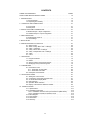
TABLE OF CONTENTS
PAGE
SAFETY AND SERVICE INSTRUCTIONS . . . . . . . . . . . . . . . . . . . . . . . . . . . . . . . . . 1-2
1. INTRODUCTION . . . . . . . . . . . . . . . . . . . . . . . . . . . . . . . . . . . . . . . . . . . . . . . . . . . 1-4
1.1 Dx 38 Features . . . . . . . . . . . . . . . . . . . . . . . . . . . . . . . . . . . . . . . . . . . 1-4
1.2 Unpacking and warranty . . . . . . . . . . . . . . . . . . . . . . . . . . . . . . . . . . . . 1-4
2. CONTROLS AND CONNECTIONS . . . . . . . . . . . . . . . . . . . . . . . . . . . . . . . . . . . . 2-1
2.1 Front panel . . . . . . . . . . . . . . . . . . . . . . . . . . . . . . . . . . . . . . . . . . . . . . 2-1
2.2 Rear panel. . . . . . . . . . . . . . . . . . . . . . . . . . . . . . . . . . . . . . . . . . . . . . . 2-3
3. INSTALLATION AND CONNECTIONS . . . . . . . . . . . . . . . . . . . . . . . . . . . . . . . . . . 3-1
3.1 Balanced input / output configuration. . . . . . . . . . . . . . . . . . . . . . . . . . . 3-1
3.2 Unbalanced input / output configuration. . . . . . . . . . . . . . . . . . . . . . . . . 3-1
4. FIRST OPERATION . . . . . . . . . . . . . . . . . . . . . . . . . . . . . . . . . . . . . . . . . . . . . . . . 4-1
4.1 Switching the power on . . . . . . . . . . . . . . . . . . . . . . . . . . . . . . . . . . . . . 4-1
4.2 Level settings . . . . . . . . . . . . . . . . . . . . . . . . . . . . . . . . . . . . . . . . . . . . 4-1
5. QUICK START . . . . . . . . . . . . . . . . . . . . . . . . . . . . . . . . . . . . . . . . . . . . . . . . . . . . . 5-1
6. CONFIGURATIONS OF THE Dx 38 . . . . . . . . . . . . . . . . . . . . . . . . . . . . . . . . . . . . 6-1
6.1 Stereo 2 Way . . . . . . . . . . . . . . . . . . . . . . . . . . . . . . . . . . . . . . . . . . . .
6.2 Stereo 2 Way / Mono Sub + Fullrange . . . . . . . . . . . . . . . . . . . . . . . . .
6.3 3 Way + Fullrange . . . . . . . . . . . . . . . . . . . . . . . . . . . . . . . . . . . . . . . .
6.4 3 Way / Mono Sub + Fullrange. . . . . . . . . . . . . . . . . . . . . . . . . . . . . . .
6.5 3 Way / Independent Sub + Fullrange . . . . . . . . . . . . . . . . . . . . . . . . .
6.6 4 Way . . . . . . . . . . . . . . . . . . . . . . . . . . . . . . . . . . . . . . . . . . . . . . . . .
6.7 2-IN-4. . . . . . . . . . . . . . . . . . . . . . . . . . . . . . . . . . . . . . . . . . . . . . . . . .
7. OPERATION. . . . . . . . . . . . . . . . . . . . . . . . . . . . . . . . . . . . . . . . . . . . . . . . . . . . . .
6-2
6-2
6-3
6-3
6-4
6-4
6-5
7-1
7.1 Program Selection . . . . . . . . . . . . . . . . . . . . . . . . . . . . . . . . . . . . . . . .
7.2 Edition . . . . . . . . . . . . . . . . . . . . . . . . . . . . . . . . . . . . . . . . . . . . . . . . .
7.3 Store Programs and Program Names . . . . . . . . . . . . . . . . . . . . . . . . .
7.4 Modifying Factory-Preset-Programs . . . . . . . . . . . . . . . . . . . . . . . . . . .
8. PARAMETERS . . . . . . . . . . . . . . . . . . . . . . . . . . . . . . . . . . . . . . . . . . . . . . . . . . . .
7-2
7-2
7-4
7-5
8-1
8.1 Parameter Access . . . . . . . . . . . . . . . . . . . . . . . . . . . . . . . . . . . . . . . .
8.1.1 Parameter Access-Table . . . . . . . . . . . . . . . . . . . . . . . . . . . . . . .
8.1.2 Parameter Link-Table . . . . . . . . . . . . . . . . . . . . . . . . . . . . . . . . .
8.2 Description of Parameters . . . . . . . . . . . . . . . . . . . . . . . . . . . . . . . . . .
9. OPTION-FUNCTIONS . . . . . . . . . . . . . . . . . . . . . . . . . . . . . . . . . . . . . . . . . . . . . .
8-2
8-2
8-3
8-3
9-1
9.1 Setting the LCD-Contrast . . . . . . . . . . . . . . . . . . . . . . . . . . . . . . . . . . .
9.2 Compressor and Limiter Threshold Unit. . . . . . . . . . . . . . . . . . . . . . . .
9.3 VU Level Meter Display Mode . . . . . . . . . . . . . . . . . . . . . . . . . . . . . . .
9.4 Edit Protection . . . . . . . . . . . . . . . . . . . . . . . . . . . . . . . . . . . . . . . . . . .
9.5 Operation Mode Selection . . . . . . . . . . . . . . . . . . . . . . . . . . . . . . . . . .
9.6 Display of the Software Revision Number. . . . . . . . . . . . . . . . . . . . . . .
10. SPECIFICATIONS . . . . . . . . . . . . . . . . . . . . . . . . . . . . . . . . . . . . . . . . . . . . . . . .
9-1
9-1
9-2
9-2
9-3
9-3
10-1
10.1 Specifications . . . . . . . . . . . . . . . . . . . . . . . . . . . . . . . . . . . . . . . . . . .
10.2 Retrofitting Instructions . . . . . . . . . . . . . . . . . . . . . . . . . . . . . . . . . . . .
10.2.1 Installation manual for the input transformer (NRS 90244) . . . .
10.2.2 Installation manuals for interface cards . . . . . . . . . . . . . . . . . . .
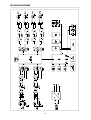
10.3 Block diagram. . . . . . . . . . . . . . . . . . . . . . . . . . . . . . . . . . . . . . . . . . .
10.4 Flow diagram . . . . . . . . . . . . . . . . . . . . . . . . . . . . . . . . . . . . . . . . . . .
10.5 Dimensions . . . . . . . . . . . . . . . . . . . . . . . . . . . . . . . . . . . . . . . . . . . .
10.6 Warranty . . . . . . . . . . . . . . . . . . . . . . . . . . . . . . . . . . . . . . . . . . . . . .
10-1
10-2
10-2
10-3
10-4
10-5
10-6
10-7
1-3
INTRODUCTION
1. INTRODUCTION
First of all, we would like to thank you for and congratulate you on buying the Electro-Voice Digital Sound
System Processor Dx 38. To ensure an optimum in the performance of the appliance and to prevent any
damage resulting from erroneous or inadvertent handling or operation, please read this owner’s manual
carefully, before operating the Dx 38.
1.1 Dx 38 FEATURES
Providing 48-bit filter algorithms, 24-bit AD/DA conversion and a dynamic range of 115 dB, the Dx 38 sets
new standards for digital loudspeaker controllers and processors. The Dx 38 is an universal Digital Sound
System Processor that provides 2 inputs and 4 outputs; plus internal summing of the inputs 1 and 2. Via
matrix it is possible to assign the outputs to any input or to the sum of the inputs. It is further possible to
establish the following configurations: Stereo or Dual 2-Way systems, 3-Way + Direct and 4-Way systems,
each with Mono Sub-channel, but also full range systems.
High and low-pass filters are provided for the frequency crossover functions in all operation modes. The
selection includes Linkwitz-Riley, Butterworth and Bessel type filters with switchable slopes between 6,
12, 18 and 24 dB/oct. A huge number of additional filters offers extremely flexible correction of the
frequency response. Each input incorporates a 5-band equalizer, allowing to assign high and low-pass,
high and low-shelving or parametric peak-dip filters to its individual filter sections. Next to the frequency
crossover filters, four additional filters are employed in each output channel, which also can be set to work
as high or low-pass, high or low-shelving filters, parametric peak-dip filters, or all-pass filters. Additional
filtering is provided through 2. order high-passes for the realization of B-6 alignment, or special LPN-filters
(Low-Pass Notch filters) for correcting the frequency and phase responses of optimally vented woofer
cabinets. Each channel additionally provides a delay, a polarity switch, a programmable level control and
a digital compressor / limiter while the master delays are located in the input channels.
The user can choose between three operation modes: the “No Edit Mode” allows to simply select the
required combination of loudspeaker systems from the factory preset program list. Afterwards, the
appliance is optimally matched to the sound system and can be operated instantly. The “Standard Edit
Mode” also uses a pre-set basic program but with the exception that here, the user has access to the
selected amount of parameters. The “Full Edit Mode” on the other hand offers access to all parameters,
allowing to freely program and store basically any setting. A total number of 80 memory addresses - 50
preset and 30 freely assignable user-programs - are available.
Within the DX 38, AD/DA conversion is taken care of by linear 24-bit converters; where the AD-section
employs 128 times oversampling, gain-ranging Sigma-Delta converters. The DA-section offers 128 times
oversampling Sigma-Delta converters. The overall signal processing is performed by two 24-bit Motorola
signal processors.
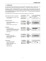
Additional features are:
-FLASH memory for software and preset updates via serial interfaces
-PC-based operation and configuration software running under Windows ‘95 / Windows ‘98
-Standard MIDI-interface
-RS-232, RS-485 interfaces or switching contacts optionally available
-Back-lit graphic-display with 122 x 32 dots
-Inputs and outputs are electronically balanced, XLR-type connectors
-Input transformer-balancing is optionally available
-Input / Output level controls, Output-Mute switch, channel function indicators SUB, LO, MID, HI
-Input / Output meter instruments, compressor and clipping LEDs
Within this owner’s manual many of the Dx 38’s extensive features are explained in detail. Keep the
manual stored at a safe place to have it at hand for any further reference.
1.2 UNPACKING AND WARRANTY
Carefully open the packaging and take out the Dx 38. Remove the protective foil from the plexiglas of the
LC-display. Next to this owner’s manual, the appliance is shipped together with mains cord and warranty
card. Please make sure that the warranty card has been completed. Only with a fully completed warranty
certificate any possible warranty claims can be granted. The appliance comes with a 36 months warranty
which is valid starting with the original date of purchase; respectively when receiving the device from your
dealer. Please keep the warranty certificate, the original invoice and also the original packaging at a safe
place for any eventual shipping.
1-4
CONTROLS AND CONNECTIONS
2. CONTROLS AND CONNECTIONS
2.1 FRONT PANEL
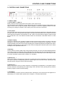
1, Control INPUT 1 / INPUT 2
Rotary controls to set the input levels of the inputs 1 and 2 of the Dx 38.
The input signal can be amplified by up to 6 dB (control set to its clockwise margin) or attenuated by any
degree. Set the level as high as possible without clipping to achieve the highest possible S/N ratio.
Checking your settings is possible via the reading of the two level meter instruments.
2, Level meters
The level meter instruments are meant for optical monitoring of the input signal levels, individually showing
the peak value of the correspondent input signal. The input control should be set to a position so that the
meter instruments indicate a level between -6 and -12 dB. To prevent internal clipping, make sure that
the clip-LEDs are not lit. Two different indication modes can be selected: “Peak Hold”-function or “Slow
Mode”.
3, Graphic display
In the PLAY mode this 122 x 32 dots LC-display shows the name of the program, its number, name and
description of the chosen loudspeaker systems, as well as the momentary active configuration. In EDIT
mode the display shows the function blocks including their individual parameters and parameter values.
Additionally and depending on the actually chosen mode, the display also indicates option menus, status
messages, short operational notes, etc.
4, EDIT-key
This key allows to enter the EDIT mode. After pressing the button, the first or the last modified parameter
of the active program is displayed. Other parameters are selected through the use of the SELECT-keys.
The individual value of the momentary displayed parameter can be altered by means of the rotary encoder.
For further information, please refer to chapter 7.2, “EDITING”.
5, SELECT-key <
While in EDIT mode, pressing the key selects the corresponding previous parameter. In the Option mode,
it is used to select the corresponding previous “Option Page” and in the Store mode, pressing this key
switches between program number and name editing.
6, SELECT-key >
While in EDIT mode, the key is used to select the corresponding next parameter. In the Option mode, it
serves to select the corresponding next “Option Page” and in the Store mode, pressing this key switches
between program number and name editing.
7, OPTION-key
The OPTION-key is used to enter the OPTION menu, allowing the user to alter and check appliance-related settings. For further details, please refer to chapter 9, “OPTION FUNCTIONS”.
2-1
CONTROLS AND CONNECTIONS
8, STORE-key
This key allows the user to store edited programs in one of the user-definable program presets (U01 U30) or to copy programs from one preset to another. For further information, please refer to chapter 7.4,
“STORE PROGRAMS AND PROGRAM NAMES”.
9, RECALL-key
Pressing this key lets you enter the PROGRAM SELECTION mode where you can select factory or
user-definable program presets through using the rotary encoder. By pressing the RECALL-key, the
selected program is acknowledged and gets loaded.
For further information, please refer to chapter 7.1, ”PROGRAM SELECTION”.
10, Rotary encoder with push-button function
While in PROGRAM SELECTION mode, rotating the encoder selects the desired program. It is activated
by pressing the RECALL-key. In EDIT mode, the encoder lets you alter parameter setting or leaf through
function blocks. Simultaneously dialing the encoder while keeping it pressed increases the speed in which
the parameter values are changed. For further details, please refer to the chapter “OPERATION” starting
on page 7-1.
11, OUTPUT-controls 1 - 4
These rotary controls are used to set the output levels of channels 1 to 4, allowing to match the Dx 38 to
the input levels of the devices chained in sequence. Correctly setting these controls results in an improved
S/N ratio. In most cases, good results are achieved when setting the controls to their center position (-6).
The digital output gain control should be used when higher output levels are needed. Use the rotary
controls OUTPUT 1 - 4 to attenuate the output levels. It is not recommended to use the digital output gain
control for massive attenuation, since this would decline the dynamic range of the D/A-converters.
The rotary controls also provide push-button-functionality, which, in the EDIT mode is used to switch
between function blocks, channel-related; i. e.: pressing a rotary control switches to the corresponding
output channel. For further details, please refer to chapter 7.2, “EDITING”.
12, MUTE-keys 1 - 4
These keys allow to mute the output signal of the corresponding output channels. Pressing a key once
switches the mute-function ON; the key’s red LED lights. Pressing the button again switches the
mute-function OFF; the key’s LED is dimmed again.
13, Channel function indicators SUB, LO, MID, HI
These LEDs indicate, which frequency band the corresponding channel is set to. If a channel is configured
for full range operation, all its function-LEDs are simultaneously lit.
14, Level meter indicators OUTPUT 1 - 4
These LEDs indicate the peak level of the corresponding outputs. The Dx 38 should be operated in a
range, so that the clip-LEDs are not lit. Otherwise, this could lead to internal clipping. The indicators can
be set to “Peak-Hold” or “Slow-Mode”.
15, Compressor indicators OUTPUT 1 - 4
The COMP-LEDs light, when the compressor / limiter of the corresponding channel is activated; e. g.:
when the audio signal level exceeded the previously set threshold and therefore the output level is
compressed or limited.
16, POWER ON/OFF-switch
This switch turns the Dx 38’s mains power on or off.
2-2
CONTROLS AND CONNECTIONS
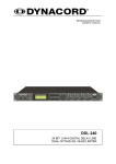
2.2 REAR PANEL
17, Mains connector
Connect the supplied mains cord to the mains connector. The Dx 38 is capable of handling mains voltages
between 90 V AC to 250 V AC, so that switching the mains on the appliance is not necessary.
18, Extension-slot for retrofitting optional interface boards
This slot offers the possibility to retrofit different interface boards. Available are: a RS-232 interface, a
RS-485 interface and a card for the connection of switching contacts (switches, relays) for remote program
selection. For further details about the cards and their installation, please refer to the chapter “RETROFITTING INSTRUCTIONS”, starting on page 11-3.
19, MIDI IN / THRU / OUT connectors
These sockets allow to control several Dx 38 via a single master unit. Exchanging memory contents in
both directions is possible as well. Via MIDI, data communication between the Dx 38 and a computer’s
desktop is possible as well, providing that a standard MIDI-interface has been installed in your PC /
Notebook.
20, OUT 1 - 4 connectors
These are the 4 balanced outputs of the Dx 38. The signals of these sockets supply different frequency
bands, depending on the appliance’s configuration (2-WAY, 3-WAY, 4-WAY). Please make sure that your
power amplifiers and/or loudspeaker systems are always connected to the correct output channel. The
individual configuration of the output channels is displayed through the “channel status indicators” on the
front panel.
The pin-assignment of the inputs and outputs is explained in detail in chapter 3.
21, IN 1 / IN 2 connectors
These are the 2 balanced inputs of the Dx 38. Each input employs a Direct Out connector which allows
to feed the unaltered input signal to another Dx 38 or to any other device that needs to be operated with
the unaltered source signal. In stereo or dual mode as well as in the monaural sub woofer mode, both
connectors (LEFT / RIGHT) have to be connected accordingly. For all other operation modes using only
the IN 1 (MONO) connector is sufficient. The pin-assignment of the inputs and outputs is explained in
detail in chapter 3. Connection-examples for different configurations are provided in chapter 6.
2-3
INSTALLATION AND CONNECTIONS
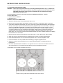
3. INSTALLATION AND CONNECTIONS
Correct connections is a vital factor in achieving the best results with the Dx 38. Before switching on the
power you have to connect the supplied European standard mains cord to the Dx 38 and your mains wall
outlet. The power supply unit of the Dx 38 automatically adapts to supply voltages in a range of 90 to 250
VAC, so that the appliance can be operated with different, country-specific mains voltages.
To prevent any trouble occurring from high temperatures inside the appliance, it is advisable not to use
the Dx 38 in environments with ambient temperatures exceeding 40°C; sufficient air-flow is also always
important. One HU is necessary for rack-installation. Normally, in this case, there are no special measures
for ventilation necessary. Like with any other LF-signal processing unit, it is not recommended to install
or operate the Dx 38 directly above or below any device that generates a massive magnetic field; e. g.
power amplifiers. In this way the risk of unwanted interference is reduced to a minimum.
Before switching the Dx 38’s power on, make sure that all necessary connections have been established.
So, make the required input and output connections in advance and in accordance to the desired
configuration.
IMPORTANT:
•
Always use correctly shielded audio cables.
•
To prevent loosing treble frequencies, especially input cords should not exceed a length
of 10 m
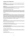
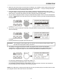
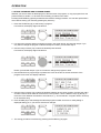
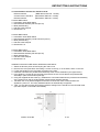
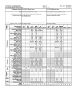
3.1 Balanced INPUT/OUTPUT configuration
For best results, the Dx 38 is operated using its balanced inputs and outputs. In this configuration, the
cable’s non-inverting conductor (+) needs to be assigned to pin 2 of the XLR-type connector while the
inverting conductor (-) is assigned to the connector’s pin 3. The shielding has to be connected to pin 1. If
the input channels supply transformers for galvanic isolation, the cable screen should not be connected
to the ground plain of the transmitting device.
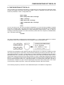
3.2 Unbalanced INPUT/OUTPUT configuration
It is also possible to operate the appliance in unbalanced input/output configuration. Therefore, the cable’s
“HOT” conductor has to be connected to pin 2 and the screen to pin 1 of the XLR-type connector.
To prevent the level being attenuated by 6dB, you have to short-circuit pins 1 and 3 of the XLR-type
connector. In case this measure leads to interference noise, removing this connection is recommended.
The following shows examples for balanced and unbalanced pin-assignments of audio cables, like they
can be used with the Dx 38.
3-1
QUICK START
5. QUICK START
This paragraph describes in an overview the most important steps for a trouble-free operation of the Dx
38 in your PA-system. For a more detailed description of specific functions and parameters, please refer
to the corresponding paragraph in the handbook.
MAINS CONNECTION
Plug in the supplied mains cord. Since the integrated power supply is capable of handling AC voltages
between 90 V and 250 V, 50 / 60 Hz, within these limits no adjustments or switching is necessary.
AUDIO CONNECTIONS
Before integrating and operating the Dx 38 in your PA-system, you should determine which system
configuration you are using. Chapter 6, CONFIGURATIONS OF THE Dx 38, provides you with a complete
description of all possible configurations including their specific input and output assignments. Connect
the appliance according to the chosen configuration. Do not feed in any audio signal yet.
POWER-ON OPERATION
After installing the Dx 38 in your PA-system setup and before operating it for the first time, please set the
input controls INPUT1 / INPUT2 all the way counterclockwise, so that at this moment no audio signal is
fed to the audio outputs. The appliance is factory-pre-set to the program F01 which is a universal preset
for stereo 2-way operation. In case the appliance had previously been operated, it can start-up with any
other program or configuration.
PROGRAM SELECTION
Together with the Dx 38 you receive a listing of all available factory presets. In case you are using a
Electro-Voice loudspeaker system that is listed, just select the corresponding program number and your
PA-system is optimally configured.
If your loudspeaker system is not listed try a Generic preset together with a suitable configuration. Generic
presets are available for all 7 configurations, offering preference settings that provide good results with
any system setup.
For direct program selection press RECALL, select the desired program using the rotary encoder and to
confirm your selection, press RECALL again (see also chapter 7.1, PROGRAM SELECTION).
LEVEL SETTING
Turn the input controls INPUT1 / INPUT2 clockwise, so that the level meters indicate values between
-12dB and -6dB; whilst there has to be only a little or no distortion at all. This guarantees best results for
the S/N ratio.
CHANGING PARAMETERS
Upon switching on the Dx 38, it always starts up in the NO EDIT mode; e. g. parameter changes are not
possible. You have to enter NORMAL or FULL EDIT mode to be able to edit parameters (see also chapter
9.8, OPERATION MODE SELECTION).
Editing factory pre-set programs is not possible. If you want to change the parameters of a factory pre-set
program, you have to copy the program to a user definable preset in advance (U01 - U30) and save this
preset under a different name (see chapter 7.4, MODIFYING FACTORY PRESET PROGRAMS).
Now you are able to change the parameter values in the EDIT menu; as described in chapter 7.2, EDITING.
X-OVER SETTINGS
5-1
QUICK START
In the Edit menu select the desired output channel by pressing the corresponding OUTPUT control. Then
use the rotary encoder to select HIPASS XOVER in the display. Here you can set the low-cut frequency
for the selected channel. Using the SELECT keys, you are able to select the parameters “Type” or “f” and
edit their values through the use of the rotary encoder. After you are done, use the left SELECT key to
re-position the cursor to the function block in the top line.
Using the rotary encoder you can now select LOPASS XOVER in the display. Here you are able to adjust
the high-cut frequency for the selected channel. Proceed as described above for the low-cut setting.
Pressing another OUTPUT control selects the control’s corresponding channel and you are able to edit
the parameter settings of this output channel. Again, proceed following the descriptions above.
Corresponding x-over frequencies and filter characteristics are linked in the Standard Edit mode; e. g.
they are changed in relation to each other. When editing the x-over’s low-cut frequency of one channel,
the corresponding high-cut of the adjacent channel is changed as well.
Parameters are not linked in the Full Edit mode. Thus, you have to make sure that related low and high-cuts
are set to the same values and filter characteristics.
LOUDSPEAKER EQUALIZATION
The Dx 38 embodies 4 EQs per channel for each output channel allowing to optimally match the frequency
response for the connected loudspeaker components; similar to the factory preset programs. In case you
want to program the EQs matching your own set of loudspeaker systems, you should know the exact
frequency response of each component to be able to utilize the channel EQs efficiently.
In the EDIT menu, select the desired output channel by pressing the corresponding OUTPUT control.
Then, by using the rotary encoder select CHANNEL EQ1 in the display. Here you are able to edit the first
filter of this channel. Through use of the right SELECT key you are able to select the parameter “Type”
and change its setting with the rotary encoder. Available for “Type” are:
PEQ (parametric Peak-Dip-Filter)
LOSLV (Low Shelving Equalizer)
HISLV (High Shelving Equalizer)
LOPASS (Lo-Pass)
HIPASS (Hi-Pass)
ALLPASS (All-Pass for phase correlation correction)
All other parameters depend on the selected filter type. A complete overview is provided in chapter 8, PARAMETERS. The
SELECT keys allow the selection of any parameter and the corresponding values are edited using the
rotary encoder.
After you are done, use the left SELECT key to re-position the cursor to the function block in the top line.
Using the rotary encoder you can now select next EQ sections to adjust its frequency response according
to your liking.
Pressing another OUTPUT control selects the control’s corresponding output channel.
DELAY ALIGNMENT
Using the channel delays, it is possible to compensate construction-related delays of loudspeaker systems
or delays that result from different positions of loudspeaker cabinets. Nevertheless, herefore, it is
necessary to know the distance between cabinets as precise as possible.
Select the desired output channel in the Edit menu by pressing the corresponding OUTPUT control. Using
the rotary encoder you can now select CHANNEL DELAY in the display. The parameters “Delay” or “Unit”
are now accessible through the use of the SELECT keys and the rotary encoder can be used to alter their
values. Afterwards, use the left SELECT key to re-position the cursor to the function block in the top line.
Pressing another OUTPUT control selects the control’s corresponding output channel.
5-2
QUICK START
COMPRESSOR / LIMITER SETTINGS
A compressor / limiter automatically reduces level peaks above a certain threshold and therefore provides
reliable protection against power amplifier clipping and damaging the connected loudspeaker systems.
In most cases it is absolutely sufficient to set the compressor’s threshold to the modulation limit of the
connected power amplifier.
Select the desired output channel in the Edit menu by pressing the corresponding OUTPUT control. Using
the rotary encoder you can now select COMPRESSOR in the display. Now, the SELECT keys can be
used to select individual parameters. Their values are altered through the use of the rotary encoder.
Afterwards, use the left SELECT key to re-position the cursor to the function block in the top line.
Using the rotary encoder you are now able to select LIMITER in the display. Proceed in the same way as
described for the compressor to make the limiter’s parameter settings for the selected channel.
Pressing another OUTPUT control selects the control’s corresponding output channel.
MATCHING THE FREQUENCY RESPONSE
Using the Master EQs in the input channels of the Dx 38, the PA-system can be easily matched to various
environmental and acoustical conditions. In many cases, a graphic equalizer which normally is employed
to perform this task is not needed any longer.
In the Edit menu, use the rotary encoder to select MASTER EQ1 in the display. Here you can adjust the
first filter of the selected input. Using the right SELECT key, you are able to select the parameter “Type”
and alter its setting through the use of the rotary encoder. Available are:
PEQ (parametric Peak-Dip-Filter)
LOSLV (Low Shelving Equalizer)
HISLV (High Shelving Equalizer)
LOPASS (Lo-Pass)
HIPASS (Hi-Pass)
All other parameters depend on the selected filter type. A complete overview is provided in chapter 8,
PARAMETERS. Using the SELECT keys, you are able to select all parameters and alter their values
through the use of the rotary encoder.
Afterwards, use the left SELECT key to re-position the cursor to the function block in the top line.
The rotary encoder can now be used to select another Master EQ to proceed with the shaping of the
frequency response. The rotary encoder also serves for selecting the second input channel.
5-3
CONFIGURATIONS OF THE Dx 38
6. CONFIGURATIONS OF THE Dx 38
The Dx 38 offers 7 pre-defined configurations. A configuration is a basic setting that includes the routing
of inputs and outputs, the function of the outputs (Sub, Lo, Mid, Hi, Fullrange), as well as the kind and
amount of parameters. These 7 configurations are:
- Stereo 2 Way
- Stereo 2 Way / Mono Sub + Fullrange
- 3 Way + Fullrange
- 3 Way / Mono Sub + Fullrange
- 3 Way / Independent Sub + Fullrange
- 4 Way
- 2-In-4
If you do not want to use one of the pre-defined configurations, you have also the possibility to operate
the Dx 38 in Full Edit mode. This mode offers access to all parameters and basically any input/output
routing can be programmed. Additionally, the output assignment (output function - Sub, Lo, Mid, Hi,
Fullrange) is also freely definable. For further information, please refer to the chapters 8, PARAMETERS,
and 9, OPTION FUNCTIONS.
- Full Edit
The active configuration is defined by the selected program; i. e.: each program is based on a specific
configuration which is also displayed next to the program number and program name.
In general, all configurations offer identical signal processing blocks. Five filters are available for either
one of the two input signals. These filters can be selected individually and used as parametric EQ’s, Low/ High-Shelving filters or Lo-Pass- / Hi-Pass filters. It is further possible to individually assign the delay’s
total delay time of 5.4 seconds to both input channels, to the sum of the two channels, and/or to the 4
outputs. Each output employs two X-Over filters (Hi-Pass / Lo-Pass). Linkwitz-Riley, Butterworth or Bessel
filters (6, 12, 18, 24 dB/oct. slope) can be selected. Each output channel provides 4 additional filters which
can be used as parametric EQs, Low- / High-shelving filters, or Lo-Pass and Hi-Pass filters, but also as
All-Pass filters. In addition to a gain control for adjusting the output level and a polarity switch, each output
is monitored by a digital compressor / limiter with adjustable threshold, attack and release.
In the following chapters you will find a more detailed description of the different configurations.
6-1
CONFIGURATIONS OF THE Dx 38
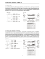
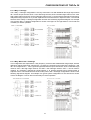
6.1 Stereo 2 Way
This configuration generally represents a 2-way stereo frequency crossover, where IN 1 serves as the
left input channel and IN 2 as the right input channel. OUT 1 is the left Low-range output and OUT 2 is
the left High-range output. OUT 3 and OUT 4 are the corresponding right Low-range and High-range
output channels. The parameters of the inputs 1 and 2 as well as the ones of the Low-range and High-range
outputs are always set to identical values; i. e.: the left and right channels are linked. The following figures
illustrate the input / output routing of a typical STEREO 2-WAY installation.
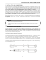
6.2 Stereo 2 Way / Mono Sub + Fullrange
This configuration represents a 2-way frequency crossover with monaural sub-channel and additional
Fullrange output. OUT 1 is the sub-channel that is fed by the summed audio signals of the inputs IN 1
and IN 2. OUT 2 and OUT 3 are the left and right High-range output channels. OUT 4 is a Fullrange output
that is also fed by the summed signal of the inputs IN 1 and IN 2. For example, this output signal can be
used to provide sound reinforcement in adjacent rooms. The parameters of the inputs 1 and 2 as well as
the ones of the two High-range outputs are always set to identical values; i. e.: the left and right channels
are linked. The following signal flow diagram is meant to illustrate the input / output routing scheme. The
figure on the right bottom shows a typical configuration with monaural sub woofer and additional Fullrange
installation.
6-2
CONFIGURATIONS OF THE Dx 38
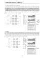
6.3 3 Way + Fullrange
The 3-Way + Fullrange configuration is a 3-way monaural x-over with additional full range output where
IN 1 serves as input channel. OUT 1 is the Sub-range channel, OUT 2 the Mid-range channel, OUT 3 the
High-range channel, and OUT 4 is the Fullrange channel. OUT 4 can be used for example for monitoring,
delayed full range-systems or to provide separate sound reinforcement in adjacent rooms. The internal
structure of the 3-Way + Fullrange configuration is shown in the following signal flow diagram. An example
of a typical 3-Way + Fullrange configuration is shown in the figure on the right bottom. Two Dx 38s are
necessary for stereo operation.
6.4 3 Way / Mono Sub + Fullrange
This configuration also represents a 3-way frequency crossover with additional full range output, with the
difference that the Sub-range channel OUT 1 is fed by the summed mono signal of the inputs IN 1 and
IN 2. The outputs OUT 2 ... OUT 4 get their signal-feed from the input channel IN 1. OUT 2 is the Mid-range
channel, OUT 3 the High-range channel, and OUT 4 the Fullrange channel. OUT 4 can be used for
instance for monitoring, delayed full range-systems or to provide separate sound reinforcement in
adjacent rooms. The internal structure of the 3-Way / Mono Sub + Fullrange configuration is shown in the
following signal flow diagram. An example of a typical system configuration for this structure is shown
next to the diagram. Two Dx 38s are necessary for stereo operation.
6-3
CONFIGURATIONS OF THE Dx 38
6.5 3 Way / Independent Sub + Fullrange
As well as the two previous configurations, this configuration also represents a 3-way frequency crossover
with additional full range output, with the difference that the Sub-range channel OUT 1 gets its signal-feed
from the input channel IN 2. Thus, it is independent from the other output channels. The audio signal for
the outputs OUT 2 ... OUT 4 is fed from the input channel IN 1. OUT 2 is the Mid-range channel, OUT 3
the High-range channel, and OUT 4 the Fullrange channel. OUT 4 can be used for instance for monitoring,
delayed full range-systems or to provide separate sound reinforcement in adjacent rooms. The internal
structure of the 3-Way / Independent Sub + Fullrange configuration is shown in the following signal flow
diagram. An example of a typical system configuration for this structure is shown next to the diagram.
Two Dx 38s are necessary for stereo operation.
6.6 4 Way
The 4-Way configuration is a monaural 4-way frequency x-over. All outputs are fed by the input channel
IN 1. OUT 1 is the Sub-range channel, OUT 2 the Low-range channel, OUT 3 the Mid-range channel, and
OUT 4 the High-range channel. The internal structure of the 4-Way configuration is shown in the following
signal flow diagram. An example of a typical system configuration for this structure is shown in the figure
on the right bottom. Two Dx 38s are necessary for stereo operation.
6-4
CONFIGURATIONS OF THE Dx 38
6.7 2-IN-4
In this configuration, all 4 outputs are configured for full range operation. OUT 1 and OUT 2 get their
signal-feed from the input channel IN 1 while OUT 3 and OUT 4 are fed from the input channel IN 2. This
structure is suitable for instance for the equalization of full range (wide-band) loudspeaker systems or
passive multi-way systems. The following signal flow diagram shows the assignment of the inputs and
outputs. An example of a typical multi-channel, full range sound reinforcement system configuration is
shown in the figure next to the diagram.
6-5
OPERATION
7. OPERATION
The rotary encoder with push-button function for fast editing of parameter values, 6 function keys, and
the push-button function of the output level controls OUT 1 - 4 are the main controls of the Dx 38.
With EDIT, OPTION, STORE and RECALL you are able to branch off to and also return from the
corresponding menus. The SELECT keys are used to choose between the different menu-pages or to
select individual parameters. The rotary encoder lets you alter the parameter values. Within the Edit menu
you can also use the push-button function of the controls OUT 1 - 4 to directly select the parameters of
the corresponding channel.
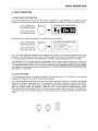
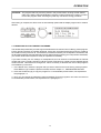
The following figure shows the different menu levels and explains how to select them.
Initial state after power-on operation
-
Last used program with program number
and configuration
Program selection
-
Activated through RECALL
Program selection via rotary encoder or
SELECT keys
Program activated through RECALL
Edit menu
-
Activated through EDIT
Function block selection via rotary encoder
Parameter selection with SELECT keys
Parameter changes via rotary encoder
Exit with EDIT
Store menu
-
Activated through STORE
Saving and copying of programs
Entering a program name
Exit with STORE
Option menu
-
Activated through OPTION
Appliance-related settings
Selection of the operation mode
Interface parameters
Password / Lock
Exit with OPTION
7-1
OPERATION
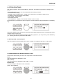
7.1 PROGRAM SELECTION
The Dx 38 offers 30 user-definable program presets (U01 - U30) and up to 50 factory pre-programmed
presets (F01-F50). Altogether you have the possibility to choose from this selection of up to 80 different
programs.
CAUTION: A program also defines the configuration and therefore also assignment of the inputs and
outputs of the Dx 38. When changing a program you have to keep in mind that also
the wiring has to be changed, if for instance a Low-range output becomes a High-range
output. Thus, an according message appears on the display, every time a program
change is performed that also includes a change of the momentary configuration.
1. After pressing the RECALL key (9) you are located in the program selection menu.
2. For selecting the desired program preset you can either use the rotary encoder (10) or the SELECT
keys (5) and (6). The display instantaneously shows the new program name and the according
configuration.
3. Activate the program by pressing the RECALL key (9). A safety dialog appears, asking you if you
really want to activate the selected program. In case the new program’s configuration differs from the
one that had been previously selected, an additional dialog on the display informs you about this
circumstance and about the possibility to probably change the wiring to prevent faulty operation and
the connected loudspeaker systems from being damaged.
4. By pressing the RECALL key (9) again, the program selection is being acknowledged. Pressing any
other key cancels the selection. Depending on your action, either the new program is activated or the
previous program stays in memory.
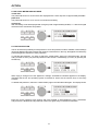
7.2 EDITING
The EDIT menu allows you to change the setting of parameters. A detailed description of all possible
settings is provided in chapter 8, PARAMETERS. The selection of accessible parameters depends on
the actual EDIT mode. For further information, please refer to chapter 9.5, OPERATION MODE
SELECTION.
1. Press the EDIT key (4).
2. You are located in the Edit menu. The display shows either the first menu-page of the active
program or the last page that you made changes to, including all accessible parameters. A menu-page
always consists of the channel (IN1, IN2, IN1+2, OUT1, OUT2, OUT3, OUT4), the function block (EQ,
X-OVER, DELAY, ROUTING, LEVEL, etc.), and the corresponding parameters (e. g. Type, f, Q, Gain
in case of an EQ). The momentary selected function block or parameter is marked by a black line.
7-2
OPERATION
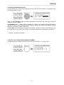
3. Whenever the function block in the first line is selected, you are able to select another function block
by using the rotary encoder (10). Pressing one of the controls OUT 1 - 4 lets you directly select the
function blocks of the corresponding output channel.
4. Using the SELECT keys (5) and (6) you are able to select the desired parameter and the rotary
encoder (10) lets you alter the value of the selected parameter. Keeping the rotary encoder pressed
while turning it, increases the speed of the value changes (enhanced step-width).
5. The set value is displayed and the change is instantaneously audible via the connected loudspeaker
systems. An E appears in the top right corner of the display, informing you that the selected program
is being edited.
In case you do not want to change any other parameters, please proceed with step 7.
6. The next or previous parameter is selected, using the SELECT keys (5) and (6). The display might
show the following:
If needed, steps 3 to 6 can be repeated as often as necessary.
7. Pressing the EDIT key (4) again quits the Edit menu.
CAUTION! Your changes to the program that is in memory are not stored yet and therefore will be
lost with the next program change command.
8. The display now shows the program number, the program name and the corresponding
configuration. The E in the top right corner indicates that parameters are being edited, but the
changes have not yet been saved. You are now faced with different possibilities to continue:
-
For saving the edited program, proceed with chapter 7.3.
For further altering the parameter values, return to step 1.
For recalling the original program, press RECALL (9). This cancels the function and discards all
previous parameter value changes of the selected program.
NOTE: In the Edit menu, pressing the STORE key (8) lets you directly jump to the Store menu to save
your program under a new name and in a new location.
7-3
OPERATION
7.3 STORE PROGRAMS AND PROGRAM NAMES
Whether you want to store an edited program, alter the name of a program, or copy a program from one
preset location to another - in all cases the necessary procedure is the same.
Pressing the STORE key (8) always starts and executes the saving procedure. You can also quit the Store
menu without saving your result by pressing any other key.
1. Press the STORE key (8) to start saving a program .
For instance, the display might look like this:
2. For saving the program without changing its name in the actual preset, proceed with step 6. If you
only want to change the program’s name and keep its location, proceed with step 4.
3. Use the rotary encoder (10) to select the desired preset location.
For instance, the display might look like this:
Please, proceed with step 6 if you do not want to change the program’s name.
4. Use the SELECT keys (5) and (6) to position the cursor to the first or the last character of the
program name. Now, the display indicates:
5. Use the rotary encoder (10) to select the desired character at the cursor position. Pressing the rotary
encoder enters a blank character at the actual cursor position. Use the SELECT keys (5) and (6) to
move the cursor between characters to be entered; e. g. “X-Over 200 Hz”. Program names can be up
to 16 characters long.
6. Press STORE (8) to acknowledge the selected program number and name. A safety dialog is
displayed asking you, if you want to save these changes.
7. The saving procedure is executed by pressing the STORE key (8) again.
7-4
OPERATION
CAUTION! The program that was previously stored in this preset location is being erased! Please
make sure, that the selected destination program number matches the number you want
to save the program under. Pressing any other key cancels the saving procedure.
After saving is complete, the Store menu is automatically quitted and the display might look for instance
like this:
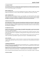
7.4 MODIFYING FACTORY PRESET PROGRAMS
The easiest and quickest way to achieve good results with the Dx 38 is the use of a factory preset program.
Factory preset programs are carefully designed, factory-pre-set programs that are stored non-volatile in
the FLASH memory of the Dx 38. Just select the preset that matches your loudspeaker combination and
the Dx 38 automatically sets all parameters to their optimal values matching your components. Afterwards,
your sound reinforcement system is ready for operation immediately.
If you want to make your own settings or re-adjustments, this can be done in the Standard or Full-Edit
modes at any time. To apply changes to a factory preset, it first has to be copied to a user-definable preset
location and the name has to be changed too. This is necessary to eliminate the chance that programs
are mistaken by each other.
1. In the Recall menu, select the program that you want to edit from the list of factory preset programs.
Press RECALL (9) to load the preset into RAM; see also chapter 7.1, PROGRAM SELECTION.
2. Press the STORE key (8) to copy the program to a user-definable preset location, like explained in
the paragraph 7.3.
3. Now, you can change the parameter values as desired. Enter the program’s new name and save it in
a user-definable preset location, like explained in the paragraph 7.3.
7-5
PARAMETERS
8. PARAMETERS
Depending on its configuration and operation mode, the Dx 38 offers a selection of more or less different
parameters. The parameters are assigned to the input channels IN1, IN2, IN1+2 and to the 4 output
channels OUT1, OUT2, OUT3, OUT4. The channel number is indicated in the top left corner of the display
while the function block (MASTER EQ, MASTER DELAY, CHANNEL EQ, etc.) is shown next to the
channel number.
The corresponding parameters appear in the second and third line of the display. A typical “parameter
display” looks like this:
The function blocks are arranged in the following sequence:
IN1:
IN1:
IN1:
IN1:
IN1:
IN1:
MASTER EQ1
MASTER EQ2
MASTER EQ3
MASTER EQ4
MASTER EQ5
MASTER DELAY
IN2:
IN2:
IN2:
IN2:
IN2:
IN2:
MASTER EQ1
MASTER EQ2
MASTER EQ3
MASTER EQ4
MASTER EQ5
MASTER DELAY
IN1+2: MASTER DELAY
OUT1: ROUTING
OUT1: CHANNEL EQ1
OUT1: CHANNEL EQ2
OUT1: CHANNEL EQ3
OUT1: CHANNEL EQ4
OUT1: HIPASS XOVER
OUT1: LOPASS XOVER
OUT1: CHANNEL DELAY
OUT1: COMPRESSOR
OUT1: LIMITER
OUT1: LEVEL
OUT2: ROUTING
OUT2: CHANNEL EQ1
OUT2: CHANNEL EQ2
OUT2: CHANNEL EQ3
OUT2: CHANNEL EQ4
OUT2: HIPASS XOVER
OUT2: LOPASS XOVER
OUT2: CHANNEL DELAY
OUT2: COMPRESSOR
OUT2: LIMITER
OUT2: LEVEL
OUT3: ROUTING
OUT3: CHANNEL EQ1
OUT3: CHANNEL EQ2
OUT3: CHANNEL EQ3
OUT3: CHANNEL EQ4
OUT3: HIPASS XOVER
OUT3: LOPASS XOVER
OUT3: CHANNEL DELAY
OUT3: COMPRESSOR
OUT3: LIMITER
OUT3: LEVEL
OUT4: ROUTING
OUT4: CHANNEL EQ1
OUT4: CHANNEL EQ2
OUT4: CHANNEL EQ3
OUT4: CHANNEL EQ4
OUT4: HIPASS XOVER
OUT4: LOPASS XOVER
OUT4: CHANNEL DELAY
OUT4: COMPRESSOR
OUT4: LIMITER
OUT4: LEVEL
All parameters, their adjustment ranges, and all additional information about use and effect of the different
functions are explained in detail in the following chapters.
8-1
PARAMETERS
8.1 PARAMETER ACCESS
Depending on the actual configuration, only certain parameters are relevant. To provide a better overview
and prevent erroneous operation, in the STANDARD Edit mode only those parameters are accessible.
Additionally and to further improve operational comfort, corresponding parameters are linked. For
Instance, in the Stereo 2-Way configuration, the Master EQs, the Master delays, the outputs OUT1 / OUT3
and OUT2 / OUT4, and the X-Over parameters are linked for mutual setting.
For information about the parameters that are accessible with a certain configuration and parameters that
are linked, please refer to the following tables.
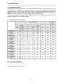
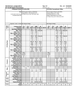
8.1.1 PARAMETER ACCESS-TABLE
STANDARD Mode
FULL
EDIT
Mode
1)
Stereo
2 Way
Stereo
2 Way /
Mono
Sub +
Fullrange
3 Way
+
Fullrange
3 Way
Mono
Sub +
Fullrange
3 Way
Independ.
Sub
+
Fullrange
4 Way
2-In-4
Full
Edit
ROUTING
NO
NO
NO
NO
NO
NO
NO
YES
IN2 EQs
YES
YES
NO
YES
YES
NO
YES
YES
IN2 Delay
YES
YES
NO
YES
YES
NO
YES
YES
IN1+2 Delay
NO
YES
NO
YES
NO
NO
NO
YES
Label
NO
NO
NO
NO
NO
NO
NO
YES
OUT1 HIPASS
XOVER
NO
NO
NO
NO
NO
NO
YES
YES
OUT1 LOPASS
XOVER
YES
YES
YES
YES
YES
YES
YES
YES
OUT2 HIPASS
XOVER
YES
YES
YES
YES
YES
YES
YES
YES
OUT2 LOPASS
XOVER
NO
NO
YES
YES
YES
YES
YES
YES
OUT3 HIPASS
XOVER
NO
YES
YES
YES
YES
YES
YES
YES
OUT3 LOPASS
XOVER
YES
NO
NO
NO
NO
YES
YES
YES
OUT4 HIPASS
XOVER
YES
YES
YES
YES
YES
YES
YES
YES
OUT4 LOPASS
XOVER
NO
NO
NO
NO
NO
NO
YES
YES
YES: Parameter is available
NO:
Parameter is not available
1
) Software-Update planned 09/99
8-2
PARAMETERS
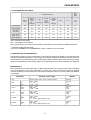
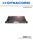
8.1.2 PARAMETER LINK-TABLE
STANDARD Mode
FULL
EDIT
Mode
1)
Stereo
2 Way
Stereo
2 Way /
Mono
Sub +
Fullrange
3 Way
+
Fullrange
3 Way
Mono
Sub +
Fullrange
3 Way
Independ.
Sub
+
Fullrange
4 Way
2-In-4
Full
Edit
IN1 / IN2 EQ
YES
YES
NO
YES
NO
NO
NO
NO
IN1 / IN2 Delay
YES
NO
NO
NO
NO
NO
NO
NO
IN1 / IN2 /
IN1+2 Delay
NO
YES
NO
NO
NO
NO
NO
NO
OUT1 / OUT3 2)
OUT2 / OUT4
YES
NO
NO
NO
NO
NO
NO
NO
OUT2 / OUT3 2)
NO
YES
NO
NO
NO
NO
NO
NO
YES: Parameters are linked
NO: Parameters are not linked
The corresponding x-over frequencies and filter characteristics of the XOVER are additionally linked.
1
)
2
Software-Update planned 09/99
) is true for CHANNEL EQ, COMPRESSOR, LEVEL, XOVER, but not for “Mute”
8.2 DESCRIPTION OF PARAMETERS
The following provides you with a description of all function blocks that can appear in any selected mode
including all available parameters, value ranges, and settings. Additional information about the affect of
each parameter is provided through the corresponding setting example. When entering the EDIT mode,
either the first parameter of the actual program or the parameter that you have edited last are displayed.
MASTER EQ1-5
Both input channels of the Dx 38 employ a 5-Band parametric EQ, each, which provide extreme flexibility
in the programming of full range equalization to match the sound reinforcement system to different
acoustic conditions and venues which in most cases makes the need for post-mix graphic equalization
unnecessary.
Parameter
Type
Settings / Value range
Default
BYPASS, PEQ, LOSLV, HISLV, HIPASS, LOPASS
BYPASS
PEQ
f
Q
Gain
20Hz - 20kHz
0.4 - 20.0
-12dB - +12dB
1.00 kHz
0.7
+0dB
LOSLV
f
Slope
Gain
20Hz - 20kHz
6dB, 12dB
-12dB - +12dB
1.00 kHz
6dB
+0dB
HISLV
f
Slope
Gain
20Hz - 20kHz
6dB, 12dB
-12dB - +12dB
1.00 kHz
6 dB
+0dB
LOPASS
f
Slope
Q
20Hz - 20kHz
6dB, 12dB
0.4 - 2.0 (for 12dB/octave slope only)
1.00 kHz
6 dB
0.7
HIPASS
f
Slope
Q
20Hz - 20kHz
6dB, 12dB
0.4 - 2.0 (for 12dB/octave slope only)
1.00 kHz
6 dB
0.7
8-3
PARAMETERS
Type describes the selected filter type. When selecting BYPASS, no effect is applied. PEQ provides a
parametric Peak Dip Filter with programmable frequency, quality, and gain. LOSLV / HISLV stand for Low
Shelving or High Shelving Equalizer, respectively. Their parameters are: frequency (f), slope, and gain.
The parameters of the LOPASS / HIPASS filters are frequency and slope.
f (frequency) sets the center-frequency of parametric EQ-types and the cutoff frequency of shelving and
Hi-Pass / Lo-Pass filters.
The value of the parameter Q determines the quality or bandwidth of parametric EQs. Higher Q-values
result in a narrow banded filter while smaller Q-values result in an increased bandwidth. The following
examples are meant to give you an idea of the effect of the Q-parameter to make correct adjustments for
your own purposes. The Q-parameter also describes the quality and therefore the graph of the Hi-Pass
and Lo-Pass filters.
Gain sets the degree of amplification or attenuation of the parametric EQ or the low shelving and high
shelving equalizers. The stepwidth is 1 dB. The response of the filter at different gain settings are shown
in the diagram below.
The Slope parameter describes the steepness or order of the filter for the low shelving or high shelving
equalizers as well as for the Lo-Pass and Hi-Pass filters. Different slope settings for the transition band
are possible. Together with the Q-parameter this provides the possibility to program the Hi-Pass filter for
so called B6-alignment; i. e. an increase in the response in the cutoff frequency range.
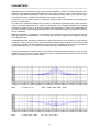
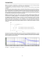
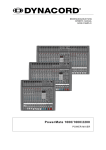
The following examples are meant to show you the effect of different parameter settings. The Dx 38 editor
software allows you to make your own adjustments via PC or notebook computer and monitor the resulting
frequency response on the computer screen.
PEQ:
f = 1kHz, Q = 2.0
Gain = +3dB, +6dB, +9dB, +12dB
PEQ:
f = 1kHz, Gain = -6dB
Q = 0.5, 1.0, 5.0, 20.0
8-4
PARAMETERS
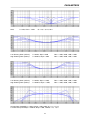
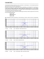
PEQ:
f = 1kHz, Gain = -12dB
Q = 0.5, 1.0, 5.0, 20.0
Low Shelving Filter (LOSLV):
High Shelving Filter (HISLV):
f = 200Hz, Slope = 6dB
f = 2000Hz, Slope = 6dB
Gain = +3dB, +6dB, +9dB, +12dB
Gain = +3dB, +6dB, +9dB, +12dB
Low Shelving Filter (LOSLV):
High Shelving Filter (HISLV):
f = 200Hz, Slope = 12dB,
f = 2000Hz, Slope = 12dB,
Gain = +3dB, +6dB, +9dB, +12dB
Gain = +3dB, +6dB, +9dB, +12dB
Hi-Pass Filter (HIPASS):f = 100Hz, Slope = 6dB, 12dB Q = 0.7, 1.0, 2.0
Lo-Pass Filter (LOPASS):f = 5000Hz, Slope = 6dB, 12dB Q = 0.7, 1.0, 2.
8-5
PARAMETERS
MASTER DELAY
These delay lines are located in the inputs IN1, IN2 and in the summed input signal IN1+2; all x-over
channels are affected.
For instance, this allows to feed different PA-towers at open air concerts with delayed signals.
The delay times are displayed in milliseconds and microseconds while the equivalent distances (unit) are
displayed in feet, inches, meters or centimeters. The environmental temperature appears as additional
parameter whenever distances are displayed. Thus, up to 3 parameters are available.
Parameter
Settings / Value range
Default
Delay
2 ms - 900 ms
1927 µs - 900000 µs
2 feet - 1014 feet
26 inch - 12169 inch
1 m - 309 m
66 cm - 30910 cm
2 ms
Unit
ms, µs, feet, inch, m, cm
ms
Temp
-20°C - 60°C
20°C
The Delay parameter determines the delay time of the corresponding channel or the distance between
different loudspeaker clusters.
Unit allows the user to select between time or distance display. Distances are automatically converted
into delay times plus the calculation additionally includes the influence of the environmental temperature.
Temp allows you to enter a value for the momentary environmental temperature. This parameter appears
only when the selected display-unit is distance. The affect of the environmental temperature on the
resulting delay time is automatically included in the calculation.
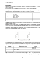
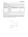
ROUTING
Any combination of input channels can be assigned to the outputs of the Dx 38. The routing defines which
input signal is fed to either one of the output channels (OUT1, OUT2, OUT3, OUT4). Besides routing the
signals of the two input channels IN1 and IN2 to one of the outputs, it is also possible to assign the
summed, monaural audio signal of both inputs IN1+2 to one of the outputs.
Parameter
Settings / Value range
Default
Source
IN1, IN2, IN1+2
IN1 (OUT 1/2)
IN2 (OUT 3/4)
Label
SUB, LO, MID, HI,
LO-MID, LO-MID-HI,
SUB-LO-MID-HI
SUB
Label allows the setting of the channel-function indicators - SUB, LO, MID, HI - on the front panel of the
appliance. These LEDs indicate the individual frequency range which the corresponding channel is
actually configured for. The LEDs are meant for indication purposes only - no parameters are changed.
8-6
PARAMETERS
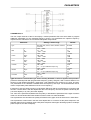
CHANNEL EQ1-4
The four output channels of the Dx 38 employ a 4-band parametric EQ each which allow to program
additional equalization for the individual frequency ranges. This guarantees the optimum frequency
response that is matched to the connected loudspeaker components.
Parameter
Type
Settings / Value range
Default
BYPASS, PEQ, LOSLV, HISLV, HIPASS, LOPASS,
ALLPASS
BYPASS
PEQ
f
Q
Gain
20Hz - 20kHz
0.4 - 20.0
-12dB - +12dB
1.00 kHz
0.7
+0dB
LOSLV
f
Slope
Gain
20Hz - 20kHz
6dB, 12dB
-12dB - +12dB
1.00 kHz
6 dB
+0dB
HISLV
f
Slope
Gain
20Hz - 20kHz
6dB, 12dB
-12dB - +12dB
1.00 kHz
6 dB
+0dB
LOPASS
f
Slope
Q
20Hz - 20kHz
6dB, 12dB
0.4 - 2.0 (for 12dB/octave slope only)
1.00 kHz
6 dB
0.7
HIPASS
f
Slope
Q
20Hz - 20kHz
6dB, 12dB
0.4 - 2.0 (for 12dB/octave slope only)
1.00 kHz
6 dB
0.7
ALLPASS
f
Order
Q
20Hz - 20kHz
1st, 2nd
0.4 - 2.0
1.00 kHz
1st
0.7
Type describes the selected filter type. When selecting BYPASS, no effect is applied. PEQ provides a
parametric Peak Dip Filter with programmable frequency, quality, and gain. LOSLV / HISLV stand for Low
Shelving or High Shelving Equalizer, respectively. Their parameters are: frequency (f), slope, and gain.
The parameters of the LOPASS / HIPASS filters are frequency and slope. The ALLPASS filter can be
used to compensate phase differences at the x-over frequency.
f (frequency) sets the center-frequency of parametric EQ-types and the cutoff frequency of shelving and
Hi-Pass / Lo-Pass filters. With the Allpass filter this is the frequency at which the phase is shifted by 90°
(1st order Allpass) or by 180° (2nd order Allpass).
The value of the parameter Q determines the quality or bandwidth of parametric EQs. Higher Q-values
result in a narrow banded filter while smaller Q-values result in a wider bandwidth.
The Q-parameter also describes the quality and therefore the graph of the Hi-Pass and Lo-Pass filters.
The Q-parameter is also found in the 2nd order Allpass filter. It is used to set the phase response in the
transition band (lower Q-settings result in flat phase response while higher Q-settings produce a steeper
phase response; see also examples).
8-7
PARAMETERS
Gain sets the degree of amplification or attenuation of the parametric EQ or the low shelving and high
shelving equalizers. The setting is performed in steps with 1 dB-stepwidth.
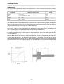
The Slope parameter describes the steepness or order of the filter for the low shelving or high shelving
equalizers.
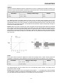
By setting the low shelving equalizer’s slope to 12 dB and the filter frequency to the resonance frequency
of the loudspeaker cabinet, the Slope parameter also lets you create a special LPN filter (Low Pass Notch
filter). This is possible, since the frequency response of speaker cabinets’ lower frequencies drops by 12
dB/oct., starting from their resonance frequency. A LPN filter compensates and shifts this polarization in
the transmission down towards lower frequencies. The picture below shows typical frequency responses
of a cabinet with LPN filter (A) and one without LPN filter (B).
Slope also describes the filter curve of the Lo-Pass and Hi-Pass filters. Different slope settings for the
transition band are possible. Together with the Q-parameter this provides the possibility to program the
Hi-Pass filter for so called B6-alignment; i. e. an increase in the response in the cutoff frequency range.
The Order parameter determines whether a 1st order or 2nd order Allpass filter is used. A 1st order
Allpass filter shifts the phase by 180° and its cutoff frequency is 90°. A 2nd order Allpass filter shifts the
phase by 360° and its cutoff frequency is 180°. Additionally, a 2nd order Allpass filter provides the
Q-parameter (quality) which allows setting the phase response of the transition range (lower Q-settings
result in flat phase response while higher Q-settings produce a steeper phase response; see also
examples).
Examples for the settings of different filter types are provided in the paragraph MASTER EQ1-5. You are
also able to program your own settings of the Dx 38 via PC or notebook computer and monitor the resulting
frequency response on the computer screen. The following example shows the phase response of Allpass
filters with different parameter settings.
ALLPASS: f = 1kHz, Order = 1st, 2nd Q = 0.7, 1.0, 2.0
8-8
PARAMETERS
HIPASS X-OVER
The frequency crossover filter consists of a low pass filter in one channel and a high pass filter in the
adjacent channel. Here, the frequency x-over filter’s Hi-Pass parameters are set. The parameters of the
corresponding Lo-Pass should be set to the same values. An x-over filter provides the parameters “Type”
and “f”.
Parameter
Settings / Value range
Default
Type
thru, 6 dB,
12dB Q0.5, 12dB Q0.6, 12dB Q0.7, 12dB Q0.8,
12dB Q1.0, 12dB Q1.2, 12dB Q1.5, 12dB Q2.0
Be{sel 12 dB, Butter 12 dB, Linkwitz 12 dB,
Bessel 18 dB, Butter 18 dB,
Bessel 24 dB, Butter 24 dB, Linkwitz 24 dB
thru
f
20Hz - 20kHz
1.00 kHz
Pol
norm, inv
norm
The Type parameter defines the filter characteristics of the x-over Hi-Pass filter. Different slopes and filter
responses (6dB, 12dB with different Q values, Bessel, Butterworth, Linkwitz-Riley) are available and the
filter can be bypassed. The corresponding Lo-Pass filter should be set to the same characteristics.
The f parameter (frequency) sets the x-over Hi-Pass filter’s cutoff frequency. The corresponding Lo-Pass
filter should be set to the same cutoff frequency.
Pol defines the polarity of the corresponding channel. Depending on the characteristic of the frequency
crossover filter, inverting the polarity of a channel’s signal may become necessary; i. e.: set a negative
polarity. Some filter types generate phase responses that lead to significant level reduction in the overall
audio signal at the crossover frequency. This negative effect can be eliminated by inverting the polarity
of the output that carries the low-frequency signal.
The following table provides you with a list of all filter types for which a channel’s signal has to be inverted
for the corresponding filter pair.
Bessel 12 dB
Butterworth 12 dB
Bessel 18 dB
Bessel 24 dB
In the Standard Edit Mode, depending on the selected type of filter, channel inversion is automatically
set.
LOPASS X-OVER
The frequency crossover filter consists of a low pass filter in one channel and a high pass filter in the
adjacent channel. Here, the frequency x-over filter’s Lo-Pass parameters are set. The parameters of the
corresponding Hi-Pass should be set to the same values. An x-over filter provides the parameters “Type”
and “f”.
Parameter
Settings / Value range
Default
Type
thru, 6 dB,
12dB Q0.5, 12dB Q0.6, 12dB Q0.7, 12dB Q0.8,
12dB Q1.0, 12dB Q1.2, 12dB Q1.5, 12dB Q2.0
Bessel 12 dB, Butter 12 dB, Linkwitz 12 dB,
Bessel 18 dB, Butter 18 dB,
Bessel 24 dB, Butter 24 dB, Linkwitz 24 dB
thru
f
20Hz - 20kHz
1.00 kHz
Pol
norm, inv
norm
The Type parameter defines the filter characteristics of the x-over Lo-Pass filter. Different slopes and filter
responses (6dB, 12dB with different Q values, Bessel, Butterworth, Linkwitz-Riley) are available and the
filter can be bypassed. The corresponding Hi-Pass filter should be set to the same characteristics.
8-9
PARAMETERS
The f parameter (frequency) sets the x-over Lo-Pass filter’s cutoff frequency. The corresponding Hi-Pass
filter should be set to the same cutoff frequency.
Pol defines the polarity of the corresponding channel. Depending on the characteristic of the frequency
crossover filter, inverting the polarity of a channel’s signal may become necessary; i. e.: set a negative
polarity. Some filter types generate phase responses that lead to significant level reduction in the overall
audio signal at the crossover frequency. This negative effect can be eliminated by inverting the polarity
of the output that carries the low-frequency signal.
The following table provides you with a list of all filter types for which a channel’s signal has to be inverted
for the corresponding filter pair.
Bessel 12 dB
Butterworth 12 dB
Bessel 18 dB
Bessel 24 dB
In the Standard Edit Mode, depending on the selected type of filter, channel inversion is automatically
set.
X-OVER:
f = 1kHz
Type = Butterworth 12dB, Butterworth 24
X-OVER:
f = 1kHz
Type = Bessel 12dB, Bessel 24d
X-OVER:
f = 1kHz
Type = Linkwitz-Riley 12dB, Linkwitz-Riley 24dB
8-10
PARAMETERS
CHANNEL DELAY
These delays are provided in the output channels OUT1 - OUT4. They are used to compensate differences
in loudspeaker dispersion plains that can be cabinet imminent or result from the positioning of individual
loudspeaker cabinets or arrays.
The delay time or acoustical distance is displayed in milliseconds, microseconds, feet, inches, meters, or
centimeters. The environmental temperature appears as additional parameter whenever distances are
displayed. Thus, up to 3 parameters are available.
Parameter
Settings / Value range
Default
Delay
0 ms - 900 ms
0 µs - 900000 µs
0 feet - 1014 feet
0 inch - 12169 inch
0 m - 309 m
0 cm - 30910 cm
0 ms
Unit
ms, µs, feet, inch, m, cm
ms
Temp
-20°C - 60°C
20°C
The Delay parameter determines the delay time of the corresponding channel or the distance between
different loudspeaker clusters.
Unit allows the user to select between time or distance display. Distances are automatically converted
into delay times plus the calculation additionally includes the influence of the environmental temperature.
Temp allows you to enter a value for the momentary environmental temperature. This parameter appears
only when the selected display-unit is distance. The affect of the environmental temperature on the
resulting delay time is automatically included in the calculation.
8-11
PARAMETERS
COMPRESSOR
The compressor automatically reduces level peaks above a certain threshold and therefore provides
reliable protection against power amplifier clipping and damaging the connected loudspeaker systems.
Parameter
Settings / Value range
Default
Thrsh
0.27V - 8.70V
8.70V
Rat
1/1.0, 1/1.4, 1/2.0, 1/4.0, 1/8.0
1/2.0
Attack
0ms - 99ms
5 ms
Rels
50ms - 999ms
250 ms
The Thrsh parameter (Threshold) defines the level at which the compressor starts operating. Signal levels
below this value are not influenced. As soon as levels reach or exceed the threshold value, the signal is
compressed according to the set value of the Ratio parameter.
Ratio - Rat - determines the compression ratio - the amount which the incoming signal is compressed.
For instance, a ratio of “1/4.0" means that a level change of 4 dB at the input results in a level change of
only 1 dB at the output; provided that the input level exceeds the threshold level.
Attack defines the time interval, after which the compressor starts to operate. With short attack settings,
the compression starts nearly instantly while with longer attack times, part of the audio signal’s impulse
can pass unaltered.
Release -Rels- sets the compressor’s release time, after the signal level has dropped again below the
threshold value. When the signal’s level drops below the threshold, the audio signal’s gain is processed
to return to its original value. This signal processing follows an exponential curve, so that the volume
change is appropriate for the human hearing. When selecting a release value that is too short, the signal
level rises too fast, which also results in pumping. On the other hand, too long release times often lead
to a dramatic loss in dynamic.
8-12
PARAMETERS
LIMITER
The limiter provides additional protection against the occurrence of clipping and overload conditions. The
maximum level of the audio signal is limited to the set threshold value. The short attack times guarantee
that even sudden peak levels are effectively attenuated.
Parameter
Settings / Value range
Default
Thrsh
0.27V - 8.70V
8.70V
Release
50ms - 999ms
100ms
The Thrsh parameter (Threshold) defines the level at which the limiter starts operating. Signal levels
below this value are not influenced. As soon as levels reach or exceed the threshold value, they are
automatically limited to this value. Normally, the limiter threshold should be set to a value that is some
dBs above the compressor threshold. This provides the best protection against loudspeaker damage as
a result from sudden peak levels.
Release defines the limiter’s release time, after the signal level has dropped again below the threshold
value. When the signal’s level drops below the threshold, the audio signal’s gain is processed to return
to its original value. This signal processing follows an exponential curve, so that the volume change is
appropriate for the human hearing. When selecting a release value that is too short, the signal level rises
too fast, which also results in pumping. On the other hand, too long release times often lead to a dramatic
loss in dynamic.
LEVEL
Each output channel employs a digital level control and a polarity switch. These controls provide the
possibility to compensate volume differences and phase shift between the different x-over channels.
Parameter
Settings / Value range
Default
Level
Off, -30.0 dB - +6.0 dB
0.0 dB
Polarity
normal, inverted
normal
The Level parameter sets the output level of the corresponding output channel. The setting can be
performed in steps of 0.5dB.
Polarity defines the polarity of the audio signals of the outputs 1 - 4 . This parameter is also accessible
in the HIPASS X-OVER or LOPASS X-OVER display windows. The corresponding descriptions provide
you with additional information about the correct setting of a channel’s polarity.
8-13
OPTION
9. OPTION FUNCTIONS
The “option programs” offer several additional, important information and preference settings for the
Dx 38.
Using the SELECT keys you can choose between the following functions:
- LCD CONTRAST setting
- COMPR & LIMIT THRESH UNIT - setting of the compressor’s and limiter’s threshold unit
- VU MODE - level meter display mode setting
- LOCK CODE - edit protection
- EDIT MODE selection
- SOFTWARE REV - display of the internal software revision number
Press OPTION (7) to activate the option programs. The last used option program appears on the display;
e. g.:
Use the two SELECT keys (5 and 6) to select the desired option page and set the corresponding values
using the rotary encoder (10).
You can leave the OPTION mode by pressing OPTION (7) again, or you can press any other MODE key
(i. e. pressing the EDIT key switches to Edit mode).
9.1 SETTING THE LCD CONTRAST
The LCD contrast or viewing angle can be set in a range of -10 (bottom view) and +10 (top view).
9.2 COMPRESSOR AND LIMITER THRESHOLD UNIT
This function allows setting the unit of the compressor and limiter threshold.
Volts:
The threshold value is displayed in volts.
dBu (0.775 V):
The threshold value is displayed in dBu (0dBu = 0.775V).
dB from Clip:
Threshold setting in dB relative to full modulation.
(0 dB = full modulation).
9-1
OPTION
9.3 VU LEVEL METER DISPLAY MODE
normal fast:
The peak hold function is off; the levels are displayed with a short drop rate of approximately 600 dB/s.
peak hold:
The peak hold function is on for a more convenient level setting.
slow decay:
With this setting, levels are displayed with a long drop rate of approximately 60 dB/s; i. e.: with lower signal
levels the meter instruments drop slower.
9.4 EDIT PROTECTION
The Dx 38 offers the possibility for edit-protection. Once this protection mode is enabled, intemal settings
cannot be altered unless the required code-number is entered first. In this way, the appliance is effectively
protected against inadvertent or faulty operation.
To activate edit-protection, you have to select the “LOCK CODE” page in the OPTION mode. Use the
rotary encoder to enter your personal password code-number. Acknowledge your entry by pressing the
STORE key.
When trying to change one of the appliance’s settings, SYSTEM IS LOCKED! appears on the display,
indicating that the Dx 38’s operating system is blocked for entries via the numeric keys or the rotary
encoder.
To disable edit-protection, select the “LOCK CODE” page in the OPTION mode again. The display shows:
Enter the correct password code number and press STORE to acknowledge the entry. Afterwards,
edit-protection is disabled and all parameter values are again freely accessible for alteration.
9-2
OPTION
9.5 OPERATION MODE SELECTION
This page allows you to choose the operation mode which the Dx 38 is operated in. The display shows
the following selection menu:
When you select NO EDIT, editing and program selection is not possible. After switching on the Dx 38
is always in NO EDIT MODE.
In STANDARD mode *1), limited editing is possible. For instance you are able to change filter settings
and edit level, delay, and compressor parameter settings. The kind and number of accessible parameters
depends on the actual selected configuration.
In FULL EDIT mode, all parameter settings are accessible. This also includes X-Over parameters and
the configuration or the routing of a program. The parameter tables of all configurations are identical.
*1) Software - Update planned 09/99
9.6 DISPLAY OF THE SOFTWARE REVISION NUMBER
The display shows the software revision of the Dx 38 host processor; e. g. Version 1.00.
9-3
SPECIFICATIONS
10. SPECIFICATIONS
10.1 TECHNICAL SPECIFICATIONS
Mains voltage
Power consumption
Safety class
90 - 250 V AC / 50 - 60 Hz
20 watts
I
Inputs
Input voltage (nominal)
Max. input voltage
Input impedance
Common mode rejection
AD-conversion
2 x XLR IN, electronically balanced, transformer optional available
2 x XLR OUT (Direct Out)
1.55 V / + 6 dBu
24.5 V / + 30 dBu
20 kohms
> 40 dB
24-bit, Sigma-Delta, 128 times oversampling, linear phase
Outputs
Output voltage (nominal)
Max. output voltage
Output impedance
Min. load impedance
DA-conversion
4 x XLR OUT, electronically balanced
1.55 V / + 6 dBu
8.7 V / + 21 dBu
< 100 ohms
600 ohms
24-bit, Sigma-Delta, 128 times oversampling
Frequency response
S/N ratio
Distortion without transformer
Distortion with transformer
20 Hz - 20 kHz (- 0.5 dB)
115 dB (typical)
< 0.01 %
< 0.05 %
Frequency crossovers
6, 12, 18, 24 dB/oct. slope; Butterworth, Bessel,
Linkwitz-Riley
26 parametric equalizers
Low-Shelving equalizer, LPN (Lowpass-Notch) switchable
Hi-Shelving equalizer, 6 / 12 dB slope switchable,
Lo-Cut filter (B-6 alignment switchable), Hi-Cut filter, All-Pass filter
4 digital compressors / limiters
3 master delays (2 ms - 900 ms)
4 channel delays (0 ms - 900 ms)
delay-increment 21 µsec.
Filters
Compressor / limiter
Delay
Data format
Sampling rate
MIDI IN / OUT / THRU
Display
Dimensions
Weight
Locking function
Accessories
Options
24-bit linear AD / DA conversion, 48-bit processing
48 kHz
Data Dump, Master / Slave operation/ Remote Control
122 x 32 Dots, graphic LC-Display with
LED-background lighting
483 x 43.6 x 374 (W x H x D in mm), 19", 1 HU
5 kg / 11 lbs
protection against inadvertent operation via function-lock
PA 1 plexiglas cover 1 HU
NRS 90244
Input transformer
NRS 90243
RS-232 interface
NRS 90247
RS-485 interface
NRS 90246
Contact Closure interface
Subject to changes without prior notice!
10-1
RETROFITTING INSTRUCTIONS
10.2 RETROFITTING INSTRUCTIONS
CAUTION: These servicing instructions are for use by qualified personnel only. To reduce the
risk of electric shock, do not perform any servicing other than that contained in the
Operating Instructions unless you are qualified to do so. Refer all servicing to
qualified service personnel.
10.2.1 Installation manual for the input transformer (NRS 90244, EDP-No. 112757):
Contents NRS 90244:
1 x Input transformer RK279
1 x Screw M2,5 x 6
Installation instructions NRS 90244:
1. Switch the Dx 38’s power off and unplug the mains cord.
2. Remove the cover plate after unscrewing 2 screws on the top, 4 on the sides, and 3 on the rear.
3. To be able to install the transformer you have to remove the printed board assembly 80448 (Analog
Board). Loosening the printed board assembly 80449 (Digital Board) is also necessary. Loosen all
screws of the Digital Board 80448 (16 screws on the rear plate which hold the sockets, 9 on the
bottom plate) and of the printed board assembly 80449 (5 screws on the bottom plate). Detach the
connections between the two printed board assemblies. Slightly lift the printed board 80448 and
carefully pull it in the direction to the front of the appliance until the sockets are out of the rear
plate. Now, you can turn the printed board assembly 80448 so that the needed contacts for installing
the transformer are accessible.
4. Remove the two resistors of the specific input channel (IN 1: R104 / R105, IN 2: R204 / R205).
5. Clean the holes for the transformer from soldering tin by suction (7 holes per transformer).
6. Insert the transformer for IN 1 into the holes at position T101 or for IN 2 at position T201.
7. Fix the transformer onto the printed board assembly by using the supplied screw.
8. Solder the contacts of the transformer on the printed board assembly (7 soldering points per
transformer).
9. Re-install all printed board assemblies in the opposite manner of their removal. Make sure that all
wire connections are re-connected and that all fixing screws are tightened in place.
10.Re-attach the cover plate and tighten its screws.
Position of the printed board assemblies inside of the Dx 38
10-2
RETROFITTING INSTRUCTIONS
10.2.2 Installation manuals for interface cards:
RS-232 Interface
Contact Closure Interface
RS-485 Interface
(NRS 90243, EDP-No. 112756)
(NRS 90246, EDP-No. 112766)
(NRS 90247, EDP-No. 112767)
Contents NRS 90243:
1 x Information sheet NRS 90243
1 x Printed board assembly RS-232 (83113)
1 x Rear plate blinding
1 x Flat wire cable 26-pole
4 x Screws M3 x 6
Contents NRS 90246:
1 x Information sheet NRS 90246
1 x Printed board assembly Contact Closure (83114)
1 x Rear plate blinding
1 x Flat wire cable 26-pole
4 x Screws M3 x 6
Contents NRS 90247:
1 x Information sheet NRS 90247
1 x Printed board assembly RS-485 (83115)
1 x Rear plate blinding
1 x Flat wire cable 26-pole
4 x Screws M3 x 6
Installation instructions NRS 90243, NRS 90246, NRS 90247:
1.
2.
3.
4.
5.
Switch the Dx 38’s power off and unplug the mains cord.
Remove the cover plate after unscrewing 2 screws on the top, 4 on the sides, and 3 on the rear.
Loosen the blinding on the rear plate (2 screws on the rear).
Install the extension kit’s printed board assembly at the correct destination (see figure below).
First, tighten the screws at the rear plate (A) and then the two screws that fix the printed board
assembly in place at the bottom plate (B).
6. Using the supplied flat wire cable (C), establish the connections between the printed board assembly
of the extension kit and the Analog Board (printed board assembly 80448).
7. Re-attach the cover plate and tighten its screws. Re-insert the mains cord and switch the
appliance’s power on. The newly installed interface is automatically recognized.
8. Now, you are able to make all necessary software settings for the interface in the OPTION mode
(see also chapter 9, OPTION FUNCTIONS).
Position of the NRS 90243, NRS 90246, NRS 90247 in the Dx 38
10-3
BLOCKDIAGRAMM
10-4
ABMESSUNGEN / DIMENSIONS
Abmessungen / Dimensions (in mm)
10-6