1
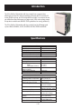
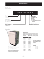
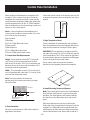
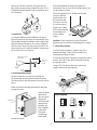
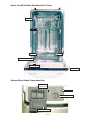
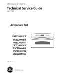
GE Consumer & Industrial
Technical Service Guide
September 2008
18-in. Dishwasher
with Top Controls
PDW1800
PDW1860
ZBD1850
ZBD1870
31-9175
GE Appliances
General Electric Company
Louisville, Kentucky 40225
IMPORTANT SAFETY NOTICE
The information in this service guide is intended for use by
individuals possessing adequate backgrounds of electrical,
electronic, and mechanical experience. Any attempt to repair a
major appliance may result in personal injury and property
damage. The manufacturer or seller cannot be responsible for the interpretation of this information, nor can it assume any liability in connection with its use.
WARNING
To avoid personal injury, disconnect power before servicing
this product . If electrical power is required for diagnosis or test
purposes, disconnect the power immediately after performing the
necessary checks.
RECONNECT ALL GROUNDING DEVICES
If grounding wires, screws, straps, clips, nuts, or washers used
to complete a path to ground are removed for service, they must
be returned to their original position and properly fastened.
GE Consumer Products
Technical Service Guide
Copyright © 2008
All rights reserved. This service guide may not be reproduced in whole or in part,
in any form, without written permission from the General Electric Company.
–2–
TABLE OF CONTENTS
Bottom Door Seal.............................................................................................................................................................. 19
Component Locator Views .......................................................................................................................................... 10
Control Panel....................................................................................................................................................................... 13
Control Panel Features ................................................................................................................................................... 8
Custom Panel Installation ............................................................................................................................................. 6
Detergent/Rinse Module................................................................................................................................................ 15
Dishwasher Components.............................................................................................................................................. 13
Dishwasher Tub Seal ....................................................................................................................................................... 19
Door Assembly ................................................................................................................................................................... 17
Door Panel............................................................................................................................................................................ 13
Door Latch Assembly...................................................................................................................................................... 14
Drain Pump Assembly .................................................................................................................................................... 24
Fill Funnel .............................................................................................................................................................................. 21
Heating Element .............................................................................................................................................................. 20
Introduction ........................................................................................................................................................................ 4
Motor Pump Assembly .................................................................................................................................................. 25
Nomenclature ................................................................................................................................................................. 5
Pressure Switch .............................................................................................................................................................. 23
Service Mode ...................................................................................................................................................................... 33
Schematic............................................................................................................................................................................. 39
Specifications .....................................................................................................................................................................
4
Static Dry System ............................................................................................................................................................. 15
Sump Assembly ................................................................................................................................................................. 27
Troubleshooting ................................................................................................................................................................ 30
Troubleshooting Check List .......................................................................................................................................... 34
Tub Thermistor .................................................................................................................................................................. 28
Warranty .............................................................................................................................................................................. 40
Washability Complaints ............................................................................................................................................... 38
Water Valve ......................................................................................................................................................................... 22
–3–
Introduction
The 18-in. Built-In Dishwasher with top controls has a compact size,
allowing the unit to fit in areas as small as 18 inches (45.72 cm) wide, 22
inches (55.88 cm) long, and 34 inches (86.36 cm) high. It is compact in size,
yet still delivers the performance of larger units. With a low power usage,
this product model meets ENERGY STAR® guidelines for energy efficiency.
The 18-in. Built-In Dishwasher with top controls has the following wash
cycles: HEAVY, NORMAL, LIGHT, GLASSES, AIR-DRY, SPEED and RINSE.
Specifications
Electrical
Rating
120 Volts, 60 Hz ±10%
Separate Circuit
4.5 to 5.5 Amps
Motor (HP)
1/5
Motor (Amps)
1 ±10%
Heater Wattage – Wash/Dry
465 ±10%
Total Amps (Load Rated)
5 ±10%
Component Resistance (OHMS)
Timer Motor
1460 ±10%
Heating Element
31 ±5%
Pump Motor Windings
Drain
27 ±10%
Wash (Blue to Red)
47 ±10%
Run Windings – Main
17.5 ±10%
(Blue to Black)
Water Valve Solenoid
1140 ±5%
Total Amps (Load Rated)
5 ±10%
Water Supply
Suggested Minimum
120 °F to 150 °F
Incoming Water Temperature (49 °C to 66 °C)
Sump Water Temperature
145 °F ±5 °F
With Outer Door In Place
(63 °C ±3 °C)
Water Charge
2.54 to 3.27 Quarts
(2.4 to 3.1 Liters)
Pressure
20 Min./120 Max. (PSI)
138 Min./827 Max. (kPa)
Connection (NPT)
3/8 In. (0.95 cm)
Consumption (Total)
4.7 to 6.1 Gallons
(17.8 to 23.1 Liters)
Water Valve Flow Rate
1.8 ±14%
(GPM)
(6.81 LPM ±14%)
Water Circulation Rate (GPM) 10 ±10%
(37.85 LPM ±10%)
Water Fill Time (Seconds)
30 (±1)
–4–
Nomenclature
Model Number
Z B D 1 8 0 0 M S S
Brand
Z = Monogram
P = Profile
Exterior Color
SS = Stainless Steel
BB = Black
WW = White
II = Custom panel and handle
required
Product Type
BD = Built-In Dishwasher
DW = Dishwasher
Model Designator
Compact 18-in.
Model Year Designator
Nomenclature
Serial Number
The first two characters of the serial number
identify the month and year of manufacture.
Example:
AR123456S = January, 2008
The serial plate of your
dishwasher is located on the tub
wall, just outside the door.
The service information sheet is
located behind the kick panel.
A - JAN
D - FEB
F - MAR
G - APR
H - MAY
L - JUN
M - JUL
R - AUG
S - SEP
T - OCT
V - NOV
Z - DEC
–5–
2008 - R
2007 - M
2006 - L
2005 - H
2004 - G
2003 - F
2002 - D
2001 - A
2000 - Z
1999 - V
1998 - T
1997 - S
The letter designating
the year repeats every
12 years.
Example:
T - 1974
T - 1986
T - 1998
Custom Panel Installation
Some models of this dishwasher are designed for
use with a 3/4-in. custom front panel. For easier
installation, the custom panel and custom handle
should be attached before installing the dishwasher.
Use the template from Pub. No. 31-30244 supplied
with the dishwasher to locate mounting screws and
spacers on the custom panel.
Locate the vertical center of the panel at the top. Use
a carpenter's square to draw a centerline from top to
bottom.
Note: A custom handle must be installed on the
custom panel. Install the custom handle 4 1/2 inches
max. from the top of the panel.
Parts Included:
(2) Brackets
(4) 1/2-in. Phillips flat-head screws
(2) Spacer pads
(2) Metal spacers
(2) 1-in. Phillips flat-head screws
(2) 3/4-in. Phillips round-head screws
3. Align Template to Panel
Trim the template on the dotted line along all sides.
Place the template on the panel aligned with the top
edge and the centerline. Use tape to hold in place.
IMPORTANT: If the template is not aligned with the
top edge of the panel, the 1/2 inch minimum gap will
not be maintained. This 1/2 inch minimum gap must
be maintained to prevent condensation and damage
to the control panel from screw heads.
1. Custom Panel Size Requirements
Height - Panel height should be 26 25/32 inches (68
cm). The top of the custom panel must be flush
with the top of the door. The 1/2-inch minimum gap
between the top of the door and the bottom of the
countertop must be maintained.
Use an awl to mark the screw hole locations
indicated on the template. Remove the template.
Width - The panel width must be 17 1/2 inches (44.4
cm). If the panel width is less than 17 1/2 inches, it will
not cover the dishwasher frame.
Note: To ensure optimum door balance
performance, the custom panel must not weigh
more than 8 lbs.
Mark center
screw holes
Countertop
Countertop
1/2
minimum
1/2"in.
minimum
Minimum
1/2 in.
Minimum 1/2"
gapgap
for clearance
clearance
2. Draw Centerline
Place the custom panel on a flat surface with the
appearance side down.
4. Install Mounting Screws and Spacers
Note: The custom panel is secured to the dishwasher
door with the metal spacers, screws and brackets
provided. The metal spacers and brackets will slip
into the slots on the dishwasher door and control
panel.
Align the metal spacers over the top pilot holes.
Ensure the thick, recessed side is facing up. Drive the
supplied 1-in. Phillips flat-head screws through the
metal spacers and into the panel. Align the brackets
over the bottom pilot holes. Ensure the curved lip is
–6–
facing up. If the back surface of the panel is not
flat, use the spacer pads provided. Drive the 1/2-in.
Phillips flat-head screws through the brackets and
into the panel.
Stand the dishwasher upright and open the
dishwasher door to remove the 2 plug buttons, one
on each side as shown.
Place the supplied 3/4-in. Phillips round-head
screws inside the
plastic sleeve and
drive through the
inner door and into
the custom panel.
Bracket
Spacer Pad
Replace the 2 plug
buttons by pressing
them firmly back
into the plastic
sleeve.
Spacer
5. Install Custom Handle
A custom handle must be installed on the panel
before the panel is secured to the dishwasher door.
The handle should be installed so that it aligns with
adjacent drawer handles, or 4 1/2 inches maximum
from the top of the panel. Secure the handle in the
same manner as the cabinet handles. Screws must
be countersunk into the panel.
Custom
panel
Caution: Do not overtighten screws. Excessive
tightening of the screws could damage door edges.
7. Check Door Balance
To check the door balance, hold the top of the
dishwasher firmly. Check the door balance by
opening and closing the door.
Screws must be countersunk into panel
If the door drops when released, increase the spring
tension. If the door rises when released, decrease
the spring tension.
4 1/2" Max
from top
of panel
Using a T25 Torx driver, adjust in the direction
shown. Adjust both sides equally.
Handle
Custom
door panel
6. Install Assembled Panel
Increase
Increase
Secure the panel to the door by inserting the
top metal spacers and bottom brackets into the
matching slots on the dishwasher door and control
panel.
Decrease
Make sure both metal spacers and both brackets
engage the slots.
Dishwasher
door
Custom panel
Decrease
Press the panel
against the
door and push
downward
until the metal
spacers and
brackets are
fully engaged
in the slots.
The panel
should align
evenly with
the top and sides.
–7–
Parts Supplied
(2) (2)
Spacer
Parts
Spacer Pads
(2) 3/4-in. Round(2) 3/4" Round-head
Head Screws
screws
Brackets
(2)(2)Brackets
(2) 1-in. Phillips
(2) 1" Phillips at-head
Flat-Head
Screws
screws
Metal spacers
(2)(2)Metal
Spacers
(4) 1/2-in. Phillips
(4) 1/2" Phillips at-head
Flat-Head Screws
screws
Control Panel Features
3
ON
OFF
1
DELAY
HOURS
1 - 24 HR.
2
HEAVY NORMAL LIGHT GLASSES AIR-DRY SPEED
LOW RINSE AID
5
RINSE
CYCLE
SELECT
CLEAN
5
1 ON/OFF
With door open, press ON/OFF button to turn the unit ON to begin operation and OFF at the end
of a wash cycle. The ON/OFF light is displayed when the dishwasher is ON.
2 WASH CYCLE
SELECTIONS
Press CYCLE SELECT button to choose wash cycle. The light under the cycle name will display to
indicate which cycle has been selected.
NOTE: All cycle times and water usage information contained in this section are approximate
values. Actual results will depend on several factors including, but not limited to, inlet water
temperature and household water pressure.
HEAVY
6.2 gallons, 125 minutes
This cycle is meant for heavily soiled dishes or cookware with dried-on or baked-on soils. This
cycle may not remove burned-on foods. Everyday dishes are safe to be used in this cycle. This
cycle also includes heated dry.
NORMAL
5.3 gallons, 100 minutes
This cycle is meant for loads of everyday dishes, glasses and cookware with medium soils that
have not been pre-rinsed. This cycle also includes heated dry.
LIGHT
4.4 gallons, 85 minutes
This cycle is meant for loads of everyday dishes, glasses and cookware with light soils that have
been pre-rinsed. This cycle also includes heated dry.
GLASSES
3.5 gallons, 65 minutes
This cycle is meant for lightly soiled glassware. This cycle has less heating during the wash and
rinse to protect your glassware. This cycle also has a lower temperature heated dry.
AIR-DRY
3.5 gallons, 50 minutes
This cycle is meant for loads of everyday dishes, glasses and cookware with light soils that have
been pre-rinsed and should air dry naturally. This cycle does not include heated dry.
SPEED
5.3 gallons, 80 minutes
This cycle is meant for loads of everyday dishes, glasses and cookware with medium soils that
have not been pre-rinsed. This cycle features reduced wash times to allow for faster cycle
completion. This cycle also has a reduced time heated dry.
RINSE
1 gallon, 10 minutes
For rinsing partial loads that will be washed later. Do not use detergent with this cycle. This cycle
does not include heated dry.
–8–
3 DELAY HOUR
SELECTION
This option allows you to delay the start of a wash cycle for up to 24 hours.
With the door open, turn the dishwasher ON by pressing the ON/OFF button; then press DELAY
HOURS button to choose the number of hours you want to delay the start of the wash cycle. The
hours will show in the display window.
NOTE: To cancel the DELAY HOURS option before the start of the cycle, repeatedly press the
DELAY HOURS button until the display is blank or reads “00.”
4 STARTING
A CYCLE
After selecting the wash cycle (Step 2) and delay hours (Step 3), if desired, close the door of the
dishwasher to start the cycle or begin the DELAY HOURS countdown. When the cycle starts, the
drain begins and approximately 60 seconds later the water fill begins.
5 STATUS
INDICATORS
LOW RINSE AID The red light will display when the rinse aid dispenser needs to be refilled with liquid rinse aid. Use
of Jet-Dry® or Cascade Crystal Clear® rinse agent removes spots and prevents new film
buildup on your dishes, glassware, flatware, cookware and plastics. See page 6 for instructions on
refilling the rinse aid dispenser.
CLEAN
The green light will display and a beep will sound to alert you that the wash cycle is complete.
–9–
Component Locator Views
Front View
(Door Panel Removed)
Right Side View (Insulation Removed)
Electronic Control Panel
Door Tension Spring
Detergent/Rinse Module
Fill Funnel
Fill Hose
Pressure
Switch Hose
Drain Pump
Pressure Switch
Access Panel
Control Panel View
– 10 –
Interior View (With Bottom Rack Removed for Clarity)
Top Rack
Spray Arm
Spray Arm
Heater
Detergent/Rinse Module
Static Dry Vent
Control Panel
Detergent/Rinse Module Compartment View
Detergent
Compartment
Sight Glass
Rinse Agent Cap
Compartment Lid
– 11 –
Interior View of Basin (With Racks Removed)
Heating Element
Filter Assembly
Spray Arm
Clamp Nut
Sump Screen
Micro-filter
Bottom View (Looking Up)
Sump
Tub Thermistor
Motor Pump
Assembly
– 12 –
Drain Pump
Capacitor
Dishwasher Components
Throughout this manual, features and appearance
may vary from your model.
Door Panel
The door panel covers the door to the dishwasher
and protects the detergent/rinse module electronics.
For custom door panel installations, see Custom
Panel Installation.
Removal
Control Panel
The control panel is located on the door assembly
behind the door panel. The control panel consists of
a 2-board push-button keypad with LED indicators
and a power board assembly.
Removal and Installation
1. Remove the door panel. (See Door Panel.)
2. Remove the 6 Phillips-head screws from the top
of the door assembly.
1. Disconnect power.
3. Remove the 2 Phillips-head screws from the
door switch and latch assembly.
2. Open the dishwasher door.
3. Remove the lower 6 Phillips-head screws from
the door panel.
4. Remove the control panel from the dishwasher
door.
Power Board
1. Remove the 2 Phillips-head screws from the
power board cover.
4. Back out the 6 Phillips-head screws that hold the
control panel cover to the door assembly 1/2
inch. Remove the door panel.
2. Mark and disconnect the terminals.
3. Remove the 2 Phillips-head screws from the
power board.
– 13 –
(Continued next page)
User Interface Boards
Door Latch Assembly
1. Disconnect the 2 wire harnesses from the power
board.
The door latch assembly is located on the door
assembly behind the control panel cover. The
dishwasher will not operate until the door is closed,
the latch engages the door catch (holding the door
firmly against the seal), and the normally open
contacts of the double-pole, single-throw door
safety switch are closed.
Removal and Installation
2. Remove the 2 Phillips-head screws from the
power board tray.
1. Disconnect the electrical supply from the
dishwasher.
2. Open the dishwasher door.
3. Remove the door panel. (See Door Panel.)
4. Remove the control panel from the dishwasher
door. (See Control Panel.)
5. Remove the 2 screws and the door latch
assembly.
3. Remove the 5 Phillips-head screws from the 2
user interface boards.
4. Remove the 2 boards and connecting wire
harnesses.
6. Remove the door switch from the door latch
assembly.
7. Tag and disconnect the appropriate wire
terminals from the door switch.
– 14 –
Static Dry System
Detergent/Rinse Module
The static dry system operates through a vent
located behind the left side of the door panel. The
vent allows hot air to exit the dishwasher tub and
gradually remove moisture.
The detergent/rinse module sends a signal to turn on
the "LOW RINSE AID" LED on the control panel when
the rinse agent is low.
The detergent/rinse module automatically dispenses
both the detergent and the rinse agent at the
appropriate times. The module is activated twice
during a wash cycle.
Removal
1. Open the dishwasher door.
2. Remove the door panel. (See Door Panel.)
3. Remove the control panel (see Control Panel)
and allow the control panel to hang against the
dishwasher door.
The first time the module is activated (1), the lever
slides up the right-hand path of the connecting rod.
4. Unscrew the static vent channel cover and
remove the assembly as shown below. Inspect
the cover for hard water/lime deposits or debris
and clean if necessary.
1
Cover
This action moves the cover catch (2) and releases
the detergent cover.
Channel
2
5. Inspect the o-ring. If the o-ring shows obvious
signs of wear or damage, replace the duct vent
and gasket assembly.
Cover
When deactivated (3), the lever resets to rest under
the notch in the center of the connecting rod.
O-Ring
Duct Vent
3
– 15 –
(Continued next page)
When activated for the second time in a cycle, the
lever lifts the connecting rod by the notch, lifting the
rinse dispenser plunger (4) and releasing the rinse
agent. When deactivated, the lever returns to its
original starting position.
5. Remove the 3 screws and bottom mounting
bracket.
4
Bracket
6. Remove the detergent/rinse module from door
assembly.
Removal and Replacement
1. Disconnect power.
2. Remove the door panel. (See Door Panel.)
3. Disconnect the 4 terminals from the detergent/
rinse module.
Detergent/Rinse Module
2
4. Remove the 3 screws and top mounting bracket.
Bracket
– 16 –
10. Mark the position of the spring bolt key in the
mounting bracket with a felt-tip marker.
Door Assembly
Removal and Replacement
1. Disconnect power.
2. Carefully pull the dishwasher out from its
installation.
Key
3. Remove the control panel. (See Control Panel.)
Bracket
4. Remove the door foam wire guide and place the
control panel on a cloth or cardboard protected
surface.
5. Remove the detergent/rinse module. (See
Detergent/Rinse Module.)
6. Remove the static dry system. (See Static Dry
System.)
7. Remove the bolt and ground wire from the door.
8. Remove the wire harness from the door.
11. Pull the spring and spring bolt key from the
mounting bracket.
12. Lift the bottom of the spring loop from the hinge
arm stud.
Wire Harness
Bolt and
Ground Wire
Note: There is a door hinge assembly on both the
left and right sides of the dishwasher. Both door
hinge assemblies must be removed in order to
remove the door. The procedure to remove the
right-side door hinge assembly is outlined in steps
9 through 19. The left-side door hinge assembly is
identical.
Loop
Stud
9. Remove the 4 screws, access panel, and toekick panel from the dishwasher.
– 17 –
(Continued next page)
13. Open the dishwasher door approximately 30
degrees.
Caution: The
star washer is
easily damaged
and should not
be reused.
14. Lift the bottom hinge arm up from the bottom
hinge, far enough to expose the hook.
Star Washer
Hook
17. Remove the hinge pin from the dishwasher door
hinge.
Lift
Hinge
Pin
15. Close the dishwasher door.
Caution: The star washer is easily damaged during
removal and should not be reused. Order a new set
of star washers (part number: WD01X10254).
16. Remove the star washer from the dishwasher
door hinge.
18. Repeat steps 3 through 10 to remove the leftside door hinge assembly.
19. Remove the dishwasher door from the
dishwasher.
– 18 –
Bottom Door Seal
Dishwasher Tub Seal
The bottom door seal prevents water leakage.
The seal is fitted in a pinched metal groove at the
bottom of the dishwasher door.
The dishwasher tub seal prevents water leakage.
The seal is fitted in a seal channel that lines the rim
of the dishwasher tub.
WARNING: The pinched metal groove is sharp.
Wear Kevlar gloves when removing or installing the
bottom door seal. Failure to comply may result in
personal injury.
Removal and Replacement
It is necessary to remove the door assembly to
access the bottom door seal. (See Door Assembly.)
The seal is pulled out from the pinched metal
groove.
1. Open the dishwasher door.
2. Grasp one end of the dishwasher tub seal and
peel it away from the seal channel.
Seal Channel
Tub Seal
Door Seal
3. Reverse the above procedure to install.
Pinched Metal Groove
To install the bottom door seal it will be necessary
to open the pinched metal groove. Make sure the
seal is seated properly in the metal groove before
pinching closed. Run your finger over the groove to
make sure it is smooth and even for a proper seal.
Note: When installing the tub seal, make sure it is
seated properly in the seal channel. Run your finger
over the seal to make sure it is smooth and even for
a proper seal. A correctly installed gasket will have
both ends of the gasket equidistant from the bottom
of the tub.
Make sure the seal
is seated properly in
the seal channel.
– 19 –
Heating Element
The heating element maintains water temperature
during the wash and rinse cycles and heats the air
during the static dry cycle. (The heating element has
an approximate resistance value of 29.5 to 32.5 Ω.)
To check operation, see step 9 of Service Mode. Allow
one minute before opening the dishwasher door
and note if heat is present.
Removal and Replacement
1. Disconnect power.
7. Remove the nut and ground wire.
2. Open the dishwasher door.
8. Remove the lock washer and spacer bracket.
3. Remove the top and bottom dishwasher racks.
Spacer Bracket
4. From underneath the dishwasher tub, locate the
wires leading to the heating element.
Lock-washer
Nut
5. Pull down the nylon covers, rubber wire
protectors, and plastic strain reliefs from the
wire terminals.
2 Wire Covers
Ground Wire
9. Release the 2 heating element clamps.
2 Wire Protectors
2 Strain Reliefs
6. Disconnect the 2 terminal lugs from the heating
element.
10. Lift up and remove the heating element from the
dishwasher.
– 20 –
4. Loosen the clamp and disconnect the fill funnel
hose from the fill funnel.
Fill Funnel
The fill funnel is mounted on the right side of the
tub. Its purpose is to provide a method of supplying
water for the wash and rinse cycles. The fill funnel
provides an air gap, which prevents wash water
from siphoning back into the water supply system if
the water pressure drops to less than atmospheric
pressure. The fill funnel also allows air into the tub
to permit airflow for dish drying.
5. Remove the fill funnel from the dishwasher.
Clamp
Fill Funnel
Removal and Replacement
Fill Funnel Hose
1. Fold back the insulation surrounding the fill
funnel assembly.
2. Open the dishwasher door.
3. Rotate the fill funnel cap counterclockwise and
remove it from the fill funnel threads.
Funnel Cap
Turn CCW
Note: Make sure that the clear plastic air tube
is looped around that part of the fill funnel that
protrudes into the dishwasher tub and mates with
the fill funnel cap.
Threads
– 21 –
5. Remove the clamp and disconnect the tub fill
hose from the water valve assembly.
Water Valve
The water valve is solenoid operated and regulated
by the electronic control. The flow of water is
controlled by a rubber flow washer capable of
maintaining a flow rate of 1.8 ±14% gallons per
minute (6.81 ±14% liters per minute) with incoming
water pressure of 20 to 120 PSI. The water valve is
mounted to the left hinge support of the dishwasher.
Tub Fill Hose
Valve Assembly
Removal and Replacement
1. Disconnect power.
Clamp
2. Remove the 4 screws, access panel, and toekick panel from the dishwasher.
6. Disconnect the 2 wires from the water fill valve
assembly.
Access Panel
Shown with access panel removed.
Toe-Kick Panel
3. Disconnect the incoming water line from the
water fill valve port.
7. Remove the 4 screws, and water fill valve from
the mounting bracket. Retain the mounting
bracket and screws.
4. Remove the 2 screws and mounting bracket
from the dishwasher.
Mounting Bracket
Mounting Bracket
Port
Shown with water line removed.
– 22 –
5. Remove the pressure switch hose from the
pressure switch.
Pressure Switch
The pressure switch is a water valve safety device.
It is located under the tub at the right, front corner.
A clear plastic tube, (the pressure switch hose), runs
from the float switch, around the fill funnel, and to
the sump.
As the dishwasher basin fills with water, the air
pressure in the pressure switch hose increases.
Normally, the electronic control regulates the
amount of time the water fill valve remains open. If
the water fill valve remains energized, the overfilling
of the basin increases the air pressure in the
pressure switch hose, causing the pressure switch to
open the circuit to the electronic control and closing
the circuit to the drain pump. The drain pump then
empties the water in the sump.
Pressure Switch Hose
6. Turn the float switch clockwise to align the
mounting tab vertically with the mounting
hole and remove the pressure switch from the
dishwasher frame.
Right side of dishwasher
showing the path of the
pressure switch hose.
Turn
Mounting Tab
Fill Funnel
Mounting Hole
Pressure
Switch Hose
7. Label and disconnect the three wires from the
pressure switch. Remove the pressure switch.
3 Terminal Lugs
Pressure Switch
Removal and Replacement
1. Disconnect power.
2. Carefully pull the dishwasher out from its
installation.
3. Remove the 4 Phillips-head screws, access panel,
and toe-kick panel from the dishwasher.
4. Remove the 10 screws and the right side panel.
– 23 –
6. Remove the 2 Phillips-head screws that attach
the pump mounting bracket to the frame.
Drain Pump Assembly
The drain pump assembly is located under the tub
at the right, rear corner. The drain pump operates
on 120 VAC and is energized 60 seconds after the
wash pump shuts down, to remove any water in the
dishwasher sump. The drain pump forces the water
out the drain line. A check valve flapper on the drain
pump prevents the dirty water from reentering the
sump.
Removal and Replacement
1. Disconnect power.
2. Carefully pull the dishwasher out from its
installation.
3. Remove the 4 Phillips-head screws, access panel,
and toe-kick panel from the dishwasher.
4. Remove the drain tube (not shown) from the
drain tube port.
Caution: The clamp is easily damaged during
removal and should not be reused. Replace the old
clamp with a new universal clamp (part number:
WH1X2036).
7. Remove the clamp from the sump interconnect
hose.
8. Remove the drain pump from the sump
interconnect hose.
Clamp
Port
Interconnect
Hose
Drain Pump
5. Label and disconnect the two wires from the
drain pump.
9. Remove and save the 2 screws, lock washers,
and mounting bracket from the drain pump.
Mounting Bracket
2 Screws
2 Lock-washers
– 24 –
Motor Pump Assembly
The motor pump assembly is located under the tub
behind the sump assembly. This dishwasher model
uses a capacitor start induction motor. The motor
rotates clockwise (as viewed from the terminal end)
and draws approximately 1 amp (±10%) at 120 VAC
(±10%).
Caution: The clamp is easily damaged during
removal and should not be reused. Replace the old
clamp with a new universal clamp (part number:
WH1X2036).
5. Remove the clamp from the motor sump
interconnect hose.
Removal and Replacement
1. Disconnect power.
2. Carefully pull the dishwasher out far enough
from its installation to access the drain pump
from the rear of the dishwasher.
Clamp
3. Label and disconnect the 2 wires to the
capacitor.
Interconnect
Hose
Caution: The clamp is easily damaged during
removal and should not be reused. Replace the old
clamp with a new universal clamp (part number:
WH1X2036).
6. Remove the clamp from the main conduit
interconnect hose.
Capacitor
Clamp
4. Label and disconnect the 2 terminals to the
motor wire connector.
Interconnect
Hose
Connector
– 25 –
(Continued next page)
Caution: The clamp is easily damaged during
removal and should not be reused. Replace the old
clamp with a new universal clamp (part number:
WH1X2036).
7. Remove the clamp from the motor to the
washer arm interconnect hose.
Lock Nut
Interconnect Hose
Clamp
As seen from right
side of dishwasher.
Note: Do not attempt to remove the Phillips-head
screw and locknut that connect the motor mount to
the dishwasher frame.
9. Pull the motor mount back far enough to
clear the motor tab, work the motor from the
attaching hoses, and remove the motor pump
assembly from the dishwasher.
8. Disconnect the ground wire from the wash
pump motor assembly.
Motor Mount
Pull Out
Motor Tab
Ground
Pull Out
Motor Pump
Assembly
As seen from rear
of dishwasher.
Motor Mount
Screw
– 26 –
6. Remove the clamp from the hose that connects
the sump to the drain pump assembly.
Sump Assembly
The sump assembly consists of the filter assembly,
micro-filter, sump clamping nut, sump gasket, and
sump. The filter assembly prevents large particles
from reaching the micro-filter and the micro-filter
prevents small particles from reaching the sump.
The filter assembly rests above the sump and the
micro-filter sits above the sump basin. The clamping
nut holds the sump gasket and sump to the bottom
of the dishwasher. The filter assembly, micro-filter,
and sump clamping nut are accessed from inside the
dishwasher. The gasket and sump are located under
the tub in front of the motor pump assembly.
Clamp
7. Open the dishwasher door and remove the
bottom rack (not shown).
Removal and Replacement
1. Disconnect power.
8. Remove the filter assembly.
2. Carefully pull the dishwasher out from its
installation.
3. Remove the 4 Phillips-head screws, access panel,
and toe-kick panel from the dishwasher.
4. Remove the pressure switch hose from the
sump.
Filter
Assembly
Pressure
Switch Hose
Sump
9. Remove the micro-filter.
Caution: The clamp is easily damaged during
removal and should not be reused. Replace the old
clamp with a new universal clamp (part number:
WH1X2036).
Micro-filter
5. Remove the clamp from the hose that connects
the sump to the wash pump motor hose.
Clamp
Interconnect
Hose
– 27 –
(Continued next page)
Note: The sump clamping nut turns
counterclockwise and may be difficult to remove. It
may be necessary to insert a screwdriver or other
tool between the clamping nut tabs to enable you to
apply sufficient torque to break the factory seal.
10. Remove the clamping nut.
Tub Thermistor
The tub thermistor is located under the tub and is
attached to the left side of the sump with 2 lock
tabs. A thermal mastic is applied to the flat side
of the thermistor where it makes contact with the
underside of the tub.
During the hot wash cycle, the thermistor senses the
water temperature and turns the heating element
off when the water reaches 128°F.
Clamp
Nut
Note: If the thermistor is not operating, the hot
wash cycle will default to a set time for the heating
element to cycle.
The thermistor has a negative coefficient. As
the temperature at the contact point on the tub
increases, the thermistor's resistance decreases. The
thermistor has an approximate resistance value of
56.5K Ω at 72°F.
Tabs
To remove the thermistor:
Note: Wear latex gloves to perform this repair.
1. Disconnect power.
2. Open the dishwasher door and remove the
bottom rack.
3. Remove the dishwasher from its installation.
4. Lay the dishwasher on its back.
5. Disconnect the thermistor wire harness.
11. Remove the sump gasket (not shown) and sump.
Wire Harness
– 28 –
(Continued next page)
6. Using a small flat-blade screwdriver, lift each of
the 2 lock tabs (one on each side) that hold the
thermistor to the sump.
Tab
7. Slide the thermistor off the sump.
Note: Before installing the thermistor, evenly apply
white thermal mastic (included in box with part)
about 0.10-in. thick over the entire disk.
– 29 –
Troubleshooting
WARNING: Always turn off the electric power supply
before servicing any electrical component, making
ohmmeter checks, or replacing any parts.
Note: After service is completed, be sure all safety
grounding circuits are complete, all electrical
connections are secure, and all access panels are in
place.
Troubleshooting the Heating Element
The heating element maintains water temperature
during the wash and rinse cycles and heats the air
during the static dry cycle. (See Specifications for
heating element wattage ratings.)
To check operation, run service mode test step 9.
(See Service Mode.) Open the dishwasher door and
note if heat is present.
1. Disconnect dishwasher from electrical supply.
Troubleshooting the Door Switch
2. Remove electrical connection from one side of
heating element and test continuity.
The door switch can be tested using an ohmmeter
and the strip circuit.
3. Measure the resistance of the heating element.
The resistance should be approximately
31 ohms.
1. Disconnect the electrical supply from the
dishwasher.
2. Remove the wire leads from the door switch.
Heating Element Strip Circuit
3. Use an ohmmeter to check the door switch for
continuity.
4. If the door switch is defective, remove it from the
latch assembly. If the door switch is good, check
to see if the controller is defective by running
the service mode test steps 6 through 10. (See
Service Mode.)
Door Switch Strip Circuit
BK
Controller
Door
Switch
BK
Pin 5 on CN1
Heater
W
W
PR
P6 on Controler
Wash Pump
W
WP
BU
Pin 9 on CN2
Drain Pump
W
W
DP
Pin 7 on CN2
R
Water Fill Valve
W
Y
Pin 3 on CN2
Dispenser
W
R/Y
Pin 5 on CN2
– 30 –
Controller
BK
W
BK
W
Heater
Pin 5 on CN1
PR
P6 on Controler
Troubleshooting the Water Valve
6. If the water valve is good, check the filter screen
and clean it, if necessary.
If the water valve is suspected of faulty operation,
refer to the strip circuit and proceed as follows:
7. If there is no voltage present at the water valve
solenoid coil, disconnect power and check
continuity through the latch switch, timer
contacts, pressure switch, and wiring. Repair
wiring, as necessary.
1. Disconnect dishwasher from electrical supply.
2. Remove the 4 Phillips-head screws securing
bottom of access panel and kick panel.
Water Level Too Low
3. Remove valve electrical leads and, using
ohmmeter, check resistance of solenoid. (See
Specifications for correct ohms reading.)
1. Turn on the dishwasher and allow the bottom of
the basin to fill with water. Listen for the water
fill cycle to stop and, when it does, open the
dishwasher door. The water level should touch
the heating element.
4. To check for proper mechanical operation of
the water valve, attach a separate 115-volt
grounded power source to the valve terminals
and metal frame of the dishwasher. Turn the
power on for a few seconds and then turn the
power off. If water flow does not stop within 2
seconds after turning the valve off, replace the
water valve.
2. If the water does not touch the heating element,
disconnect power, close the door, and check the
incoming water pressure. A minimum incoming
water pressure of 20 PSI (138 kPa) is needed to
properly fill the dishwasher basin.
Water Fill Valve Will Not Shut Off
Water Fill Valve Strip Circuit
Controller
BK
W
BK
W
Pin 5 on CN1
Y
1. Turn on the dishwasher and allow the bottom of
the basin to start filling with water. Disconnect
power while the basin is filling. If water
continues to flow, turn off the water supply and
replace the water fill valve.
2. If the water turns off when power is
disconnected, troubleshoot the electronic
control. Replace the defective part.
Pin 3 on CN2
Water Fill Valve
No Water To Tub
1. Be sure the main water supply and electrical
power are turned on.
2. Remove both the service panel and the kick
panel.
3. Run service mode test step 6. (See Service Mode.)
4. Use a voltmeter to check for voltage at the
water valve solenoid coil.
5. If voltage is present, disconnect power and
measure resistance of the water fill valve
solenoid coil. (See Specifications for correct
ohms reading.) Replace the water valve, if it is
defective.
– 31 –
(Continued next page)
Troubleshooting the Wash Pump Motor
The wash pump motor does not start immediately
when the dishwasher cycle has started. The tub
will begin filling with water and the motor will start
approximately 40 seconds into the fill cycle. If the
motor hums, but will not start, make certain the
pump impeller is free from obstructions and the
motor shaft can turn freely. If the capacitor is open
or shorted, the motor will hum and will not start.
Check for 120 VAC (±10%) at the wash pump motor
terminals. Take the voltage measurement while
"under load" (as the motor is trying to start). This will
eliminate the possibility of a poor wiring connection.
If the 120 VAC (±10%) is present and the motor will
not start, the motor will have to be replaced.
Wash Pump Motor Strip Circuit
Controller
BK
W
BK
W
Pin 5 on CN1
WP
BU
Pin 9 on CN2
Wash Pump
– 32 –
Service Mode
– 33 –
Troubleshooting Checklist
The troubleshooting checklist is common for all
dishwasher models. They use different parts to
accomplish the same thing and diagnosis will remain
similar.
The wiring diagram, schematic, and service mode
test are a necessity when making electrical checks.
In most cases, an ohmmeter will handle all the tests
necessary.
When a problem arises, and a possible cause
is listed, follow the test and remove or replace
procedures as outlined in this Technical Service
Manual.
To verify the setup of any particular cycle of
operation, refer to Control Panel Features.
Symptom
Check for the Following
Remedy
Dishwasher will
not operate when
turned ON.
1. A blown fuse or tripped circuit
breaker.
1. Replace the fuse or reset the
breaker.
2. Damaged or defective wiring.
2. Repair the wiring.
3. Improper motor resistances.
3. Replace the motor.
4. Defective door switch
contacts.
4. Replace the door switch.
5. Defective door latch.
5. Replace the door latch.
Dishwasher runs
but will not heat.
1. Heater element is open.
1. Replace the heater element.
2. Damaged or defective wiring.
2. Repair the wiring.
Dishwasher runs
but will not stop.
1. Electronic control inoperative.
1. Replace the electronic control.
2. Damaged or defective wiring.
2. Repair the wiring.
Dishwasher runs
with door open.
1. Defective door safety switch.
1. Replace the door safety
switch.
Motor hums but
will not start or
run.
1. Defective motor bearings.
1. Replace the motor.
2. Defective motor capacitor.
2. Replace the motor capacitor.
Motor trips
out on internal
thermal overload
protector.
1. Improper motor voltage.
1. Replace the motor.
2. Motor shaft binding.
2. Replace the motor.
3. Motor windings shorted.
3. Replace the motor.
Etching on
glassware.
1. Soft water condition (Natural
or artificial).
Dishwasher
continues to fill
even though
there is no
voltage to the fill
valve (flooding
condition).
1. Defective water fill valve.
2. Debris buildup under the
diaphragm in the water fill
valve.
1. Have a sample of the water
analyzed by the local water
department.
1. Replace the water fill valve.
2. Clean out the debris or
replace the water fill valve.
– 34 –
(Continued next page)
Symptom
No heat during
the dry cycle.
Dishwasher will
not fill with water
or will not fill
properly.
.
Dishwasher will
not pump out.
Water siphons
out.
Too much water
fill.
Water leaks from
dishwasher.
Check for the Following
1. Defective heater element.
2. Damaged or defective wiring.
1. The water supply is turned
off.
2. Low water pressure.
3. Defective water fill valve.
4. Obstructed water fill valve or
hose.
5. Damaged or defective wiring.
6. Defective pressure switch.
7. Heavy water usage
elsewhere in home.
1. Defective drain pump.
2. Defective impeller.
3. Defective electronic control.
1. Drain hose loop too low.
2. Drain line connected to a
floor drain not properly vented.
1. Defective water fill valve.
1. Too much water fill.
2. Defective tub seal.
3. Defective vent plate.
4. Dishwasher door not level.
5. Dishwasher not level.
6. Soap suds leak from
dishwasher.
7. Loose hose clamps.
8. Loose heater element.
9. Defective water seals.
10. Motor and pump assembly
not seated properly in tub liner
bottom.
– 35 –
Remedy
1. Replace the heater element.
2. Repair the wiring.
1. Turn the water supply on.
2. Minimum water pressure of
20 PSI.
3. Replace the water fill valve.
4. Disassemble and clean the
water fill valve and hose.
5. Repair the wiring.
6. Replace the pressure switch.
7. Use dishwasher when water
usage is at a minimum.
1. Replace the drain pump.
2. Replace the impeller.
3. Replace the electronic
control.
1. Move the drain hose to the
proper height.
2. Install a vent air gap at
counter top.
1. Replace the water fill valve.
1. See previous symptom.
2. Replace the tub seal.
3. Replace the vent plate.
4. Adjust the dishwasher door.
5. Level the dishwasher.
6. Refer to use and care
manual.
7. Tighten or replace hose
clamps.
8. Tighten heater element
mounting nuts.
9. Replace the water seals.
10. Remount the motor and
pump assembly in the tub liner
bottom.
(Continued next page)
Sympton
Poor washability.
Check for the Following
1. Improper loading of dishes,
pots, pans, and nesting of
silverware.
2. Defective spray arm.
3. Water level should cover
heating element.
4. Defective detergent/rinse
module.
5. Old, improper amount, or
wrong type of detergent used
(detergents lose effectiveness
in a damp area).
6. Low incoming water
temperature.
7. Clogged filter assembly.
Poor drying of
dishes.
1. Improper loading of dishes,
pots, pans, and nesting of
silverware.
2. Low incoming water
temperature.
3. Water remaining in tub after
drain cycle is completed.
4. Defective heating element.
Door will not
latch.
Noisy pump
assembly.
Detergent left in
the dispenser.
5. Damaged or defective
wiring.
1. Defective door latch.
5. Repair the wiring.
1. Defective motor bearings.
1. Replace the pump motor.
2. A sucking sound is heard at
the end of the cycle.
1. Detergent allowed to stand
too long in the dispenser.
2. This is a normal condition.
2. Dispenser was wet when
detergent was added.
3. Detergent is binding on
detergent/rinse module cover.
4. Detergent cup held closed or
blocked by large dishes.
cycle is completed.
Remedy
1. Instruct the customer on
proper loading of the dishwasher.
Refer to the Owner's Manual.
2. Check spray arm for proper
rotation.
3. See “Dishwasher will not
fill with water or will not fill
properly” symptom.
4. Replace the detergent/rinse
module.
5. Instruct the customer on
proper use of dishwasher
detergent. Refer to the Owner's
Manual.
6. Incoming water temperature
of 120°F is required to properly
dissolve dishwashing detergents.
7. Clean the filter assembly and
microfilter.
1. Instruct the customer on
proper loading of the dishwasher.
Refer to the Owner's Manual.
2. Incoming water temperature
of 120°F is required to properly
dissolve dishwashing detergents.
3. See “Dishwasher will not pump
out” symptom.
4. Replace the heating element.
– 36 –
1. Replace the door latch.
1. Instruct the customer on
proper use of dishwasher
detergent. Refer to the Owner's
Manual.
2. Instruct the customer on
proper use of dishwasher
detergent. Refer to the Owner's
Manual.
3. Replace the heating element.
4. Instruct the customer on
proper loading of dishwasher.
Refer to the Owner's Manual.
(Continued next page)
Symptom
Noisy pump
assembly.
Spotting or
filming on glasses
(reposition of
food soil).
.
Check for the Following
1. Debris in bottom of tub sump
area.
2. Pump parts were not properly
installed.
3. Impellers are not properly
shimmed or are rubbing.
4. Defective motor bearings.
5. A sucking sound is heard at the
end of the cycle.
1. Detergent allowed to stand too
long in the dispenser or excessive
amounts of detergent are being
used.
2. Low incoming water
temperature.
3. Improper loading of dishes,
pots, pans, and nesting of
silverware.
4. Water high in mineral content.
5. High incoming water
temperature.
6. Improper installation of the
dishwasher to a food waste
disposal.
– 37 –
Remedy
1. Clean out the sump area.
2. Inspect the pump and
correct any installation errors.
3. Use the shim gage furnished
in the impeller seal kit. When
the seal is properly shimmed
the impellers will be in the
correct operating position.
4. Replace the motor.
5. This is a normal condition.
1. Instruct the customer on
proper use of dishwasher
detergent. Refer to the Owner's
Manual.
2. Incoming water temperature
of 120°F is required to
properly dissolve dishwashing
detergents.
3. Instruct the customer
on proper loading of the
dishwasher. Refer to the
Owner's Manual.
4. Have water analyzed. Use
of commercially available
rinse agents (such as Jet Dry)
helps to reduce the spotting by
lowering the surface tension
of the water (the water then
“sheets” off the dishes).
5. Incoming water temperature
of 160°F or higher will cause
high protein food particles to
bake onto the dishes before
detergent can remove them.
Set water heater tank to deliver
120°F water.
6. Install properly. Refer to
Installation Manual.
Washability Complaints
Rinse Agent – Use rinse agent if spotting or drying
is a problem. A rinse agent will improve the water
sheeting action and drying performance.
Hot Water – Ample supply of water at a
temperature of 120°F (60°C) is necessary for best
results. Do not use dishwasher soon after using
clothes washer or filling bathtub.
Water Valve – (See Water Valve.)
Loading - Consult Owner’s Manual on loading
procedures.
Spray Arm – Check to be sure the spray arms spin
freely and jets are not clogged. Check to be sure
the middle spray arm water conduit is connecting
properly to the main conduit.
Amount of Water – Make sure dishwasher is
level. Check water level, allowing dishwasher to
fill normally for first fill. The water level should be
to the heating coil. If water level is low, check for
clogged screen and check pressure switch. (See
Water Valve.)
Drying – Water inlet temperature must be at least
120°F (48.9°C) for proper drying. Low water inlet
temperature will prevent proper convection air
movement and increase drying time substantially.
Detergent/Rinse Module Leakage – Some moisture
in cup is normal. Detergent must not be soaking
wet, oozing out, and down the inner door panel. If a
leak is detected, check the detergent/rinse module
door lid, latch operation, and gasket seal. (See
Detergent/Rinse Module.)
Proper Amount of Detergent – Use full detergent
cup of fresh detergent in hard water. Use only
enough detergent to get good wash performance in
soft water.
Latch
Sight Glass
Detergent Compartment
Rinse Agent Cap
Compartment Lid
– 38 –
Schematic
WARNING: Power must be disconnected before servicing the appliance.
Note: Resistance of thermistor at room temperature:
50k Ω with a negative coefficient.
Note: Schematic diagram subject to change. Please refer to
diagram supplied with product located behind the kick plate.
– 39 –
120V
60Hz
Warranty
GE Dishwasher Warranty.
All warranty service provided by our Factory Service Centers,
or an authorized Customer Care® technician. To schedule service,
on-line, 24 hours a day, visit us at GEAppliances.com, or call
800.GE.CARES (800.432.2737).
Staple your receipt here.
Proof of the original purchase
date is needed to obtain service
under the warranty.
For The Period Of:
GE Will Replace:
One Year
From the date of the
original purchase
Any part of the dishwasher which fails due to a defect in materials or workmanship. During
this full one-year warranty, GE will also provide, free of charge, all labor and in-home service
to replace the defective part.
What GE Will Not Cover:
■ Service trips to your home to teach you how to use
the product.
■ Damage to the product caused by accident, fire, floods
or acts of God.
■ Improper installation.
■ Incidental or consequential damage caused by possible
defects with this appliance.
■ Failure of the product if it is abused, misused, or used for
other than the intended purpose or used commercially.
■ Replacement of house fuses or resetting of circuit
breakers.
■ Cleaning or servicing of the air gap device in the
drain line.
This warranty is extended to the original purchaser and any succeeding owner for products purchased for home
use within the USA. Proof of original purchase date is needed to obtain service under the warranty. In Alaska, the
warranty excludes the cost of shipping or service calls to your home.
Some states do not allow the exclusion or limitation of incidental or consequential damages. This warranty gives
you specific legal rights, and you may also have other rights which vary from state to state. To know what your
legal rights are, consult your local or state consumer affairs office or your state’s Attorney General.
Warrantor: General Electric Company. Louisville, KY 40225
– 40 –