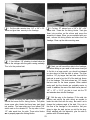
1
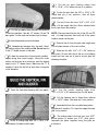
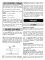
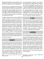
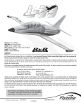
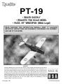
TM
PT-19
• BUILDS QUICKLY
• REALISTIC FUN SCALE MODEL
• HUGE, 89" WINGSPAN (IMAA Legal)
READ THROUGH THIS INSTRUCTION MANUAL FIRST. IT CONTAINS
IMPORTANT INSTRUCTIONS AND WARNINGS CONCERNING THE ASSEMBLY
AND USE OF THIS MODEL
WARRANTY
Dynaflite guarantees this kit to be free from defects in both material and workmanship at the date of
purchase. This warranty does not cover any component parts damaged by use or modification. In no
case shall Dynaflite's liability exceed the original cost of the purchased kit. Further, Dynaflite reserves
the right to change or modify this warranty without notice. In that Dynaflite has no control over the
final assembly or material used for final assembly, no liability shall be assumed nor accepted for any
damage resulting from the use by the user of the final user-assembled product. By the act of using
the user-assembled product, the user accepts all resulting liability. If the buyer is not prepared to
accept the liability associated with the use of this product, return this kit immediately in new and
unused condition to the place of purchase.
©Copyright 1997
PT19P03 Printed in USA
At Dynaflite we take pride in offering kits that are
simple and straight forward to build and provide
value for your modeling dollar. Because of the size
and cost of this model we assume you have built
several models and have a general working
knowledge of modeling and its terms. If you HAVE
NOT built and flown several kits, do yourself a favor
and get some experience before beginning this kit.
Introduction ......................................................2
Precautions.......................................................3
Preparations.....................................................3
Required Accessories .......................................3
Suggested Supplies .........................................3
Optional Accessories .......................................4
Building
Notes.................................................4
Adhesives .......................................................4
Common Abbreviations....................................5
Types of Wood ................................................5
Metric Conversion............................................5
Die Patterns ................................................6&7
Build the Fuselage ...............................................8
Build the Wing .....................................................12
Build theAilerons ...........................................................16
Build the Stabilizer & Elevators ...........................17
Build the Vertical Fin & Rudder .........................19
Mount the Wing to the Fuselage .........................20
FinalAssembly .................................................22
Finishing..........................................................26
Set The Control Throws...................................27
Balance Your Model.......................................27
Your PT-19 is not a toy, but a sophisticated working
model that functions like a full-size airplane. Because
of its performance, if you do not assemble and
operate the PT-19 correctly, you could possibly injure
yourself or spectators and damage property.
To make your R/C modeling experience totally
enjoyable, we recommend that you get assistance
with assembly and your first flights from an
experienced, knowledgeable modeler. You'll learn
faster and avoid risk to your model before you're
truly ready to solo. Your local hobby shop has
information about flying clubs in your area whose
membership includes qualified instructors.
Preflight..................................................27
At Home...............................................................27
At the Flying Site ...........................................28
Engine Safety Precautions................................28
FLYING.............................................................28
Find a Safe Place to Fly..................................28
Takeoff..........................................................29
Flight.........................................................29
Landing ........................................................29
Terms & Definitions ........................................30
Cockpit & Wing Tip Patterns...........Center Spread
You can also contact the national Academy of Model
Aeronautics (AMA), which has more than 2,300
chartered clubs across the country. We recommend
you join the AMA which will provide you with
insurance coverage at AMA club sites and events.
AMA Membership is required at chartered club
fields where qualified flight instructors are available.
Contact the AMA at the address or toll-free phone
number below.
Academy of Model Aeronautics
5151 East Memorial Drive
Muncie, IN 47302
(800) 435-9262
Fax (765) 741-0057
Congratulations on your choice of this kit for your
next project. The Fairchild PT-19 is a Fun Scale®
model of a true classic aircraft and has the presence
that only a big model can carry off.
2
1. You must assemble the plane according to the
instructions. Do not alter or modify the model, as
doing so may result in an unsafe or unflyable model.
In a few cases the instructions may differ slightly
from the photos or plan. In those instances the
written instructions should be accepted as correct.
These are the items "not included" with your kit, that
you will need to purchase separately. Items in
parentheses (GPMQ3141) are suggested part
numbers recognized by distributors and hobby
shops and are listed for your ordering convenience.
GPM is the Great Planes® brand, TOP is the Top
Flite® brand and HCA is the Hobbico® brand.
2. You must take time to build straight, true and strong.
4 channel radio with 3 standard, 2 high torque
and one quarter scale servo.
Engine - 1.08 to 1.5 2-stroke or 1.2 to 1.6
4-stroke
Engine mount and mounting hardware
16oz.Fueltank(GPMQ4107)
Standard fuel tubing (GPMQ4131)
(2) 5" to 6" main wheels
(1) 1-1/2" tail wheel (GPMQ4243)
(4) 1/4" Wheel collars (DUBQ1200)
(2) 1/8" Wheel collars (GPMQ4304)
Top Flite® MonoKote® covering film (4 rolls)
or Coverite™ 21 st Century® Fabric
Paint for fuelproofing, the engine cowl and
the windshields
( 1 ) O R ( 2 ) 1/3 Scale pilot(s)
1/4" Latex Foam Rubber (HCAQ1000)
3. You must install all R/C and other components so
that the model operates properly on the ground and
in the air.
4. You must test the operation of the model before the
first and each successive flight to insure that all
equipment operates correctly. You must also make
certain that the model has remained structurally sound.
NOTE: We, as the kit manufacturer, can provide
you with a quality kit and great instructions, but
ultimately the quality and flyability of your finished
model depends on how you assemble it; therefore,
we cannot in any way guarantee the performance
of your completed model and no representations
are expressed or implied as to the performance or
safety of your completed model.
These are the adhesives and supplies that you will
need to build your Pt-19. We recommend Great
Planes Pro™ CA and Epoxy
Please inventory and inspect all parts carefully
before starting to build! If any parts are missing,
broken or defective or if you have any questions
about building or flying this model, please call us at
(217) 398-8970 and we'll be glad to help. If you are
calling for replacement parts, please look up the
part numbers and have them ready when calling.
4 oz. Thin CA Adhesive - (GPMR6004)
2 oz. Thick CA Adhesive - (GPMR6015)
CA Accelerator - (HCAR3750)
CA Applicator Tips - (HCAR3780)
6-Minute Epoxy - (GPMR6045)
30-Minute Epoxy - (GPMR6047)
4 oz. Aliphatic Resin Glue (GPMR6161)
3
IMPORTANT: During construction you will be using a
number of balsa sticks to frame various assemblies.
Ample material is included but you should study the
plans, then make an effort to cut the longest pieces
you will need first. Label the pieces as you cut them
for later reference. By doing this now, you won't
have to splice pieces together later.
A flat, durable, easy-to-handle sanding tool is a
necessity for building model airplanes. Great Planes
makes a complete range of Easy-Touch'" Bar Sanders
and replaceable Easy-Touch adhesive-backed
sandpaper. On our workbench, we have four 11"
Easy-Touch Bar Sanders, equipped with #50, #80,
#150 and #220-grit sandpaper. This setup is all that is
required for almost any sanding task. Custom sanding
blocks can be made from balsa for sanding hard-toreach spots. We also keep some #320-grit wet-or-dry
sandpaper for finish sanding before covering.
This kit is built with three types of glue.
For future reference, here's a list of Easy-Touch Bar
Sanders and adhesive-backed sandpaper:
Cyanoacrylate: CA glues cure almost instantaneously
and are moderately strong. There are different
viscosities of CA's intended for different conditions
you will encounter when you build. Thin CA is great
for "tack-gluing," for glue joints that fit well and for
parts that are already joined but need to be
permanently bonded. Medium CA is used for general
construction where you apply glue to one part, then
join it to another part. Thick CA is great for glue joints
that don't fit perfectly or parts that require a little time
for positioning before the glue cures. You will
encounter many other conditions that require one or
the other types of CA.
5-1/2" Bar Sander (GPMR6169)
11 "Bar Sander (GPMR6170)
22" Bar Sander (GPMR6172)
12' Roll of adhesive-backed sandpaper,
80-grit (GPMR6180)
150-grit (GPMR6183)
220-grit (GPMR6185)
Assortment pack of 5-1/2" strips (GPMR6189)
Always use CA in a well ventilated area. Open some
windows or place a fan in the room to circulate the
air. Do not lean directly over your work when you
use CA and look away while it cures or "sets off."
CA can cure immediately upon contact with skin so
if you accidentally bond your fingers, do not use
vigorous motion to separate them. Use CA Debonder
(GPMR6039) or acetone (nail polish remover) or
soak your fingers in warm water for a few minutes.
Robart Oleo landing gear struts (ROBQ1600)
Midwest scale instrument panel (MIDQ1105)
4
Never point the tip of a CA bottle toward your face
and be especially careful when you unclog a CA tip.
Hobbico CA Applicator Tips (HCAR3780) are highly
recommended and will help keep the bottle from
clogging. Keep paper towels or tissues close by to
immediately absorb excess CA dropped on your
model or work area. Read all the warning labels on
your CA bottle. CA Accelerator is a chemical that
you can spray over uncured CA to make it cure
immediately. A mist spray of accelerator will do the
job. Do not inhale the vapors! Some modelers
"preprime" the parts to be glued with accelerator,
join them, then add the CA. This way the CA is
guaranteed to cure immediately. This prepriming is
especially handy when you use thin CA because it
will cure before all of the glue soaks into the wood
away from the glue joint. We do not recommend
you build your entire model with this method and
use accelerator only when necessary. Often,
overspray from accelerator used hours or even days
earlier on nearby glue joints will cause the CA you
use on the next step to cure prematurely and
unexpectedly - so be careful!
Fuse = Fuselage
Ply = Plywood
" = Inches
Balsa
Aliphatic Resin - Resin glues require that parts be
pinned or clamped together while the glue dries/typically 1 5 - 3 0 minutes. Resin glues are very
strong and work well with balsa and plywoods.
Epoxy - Epoxy glues are the strongest but require the
most time to cure. Six-minute epoxy cures the fastest;
it sets within six minutes but is not fully cured for one
hour or more. Thirty-minute epoxy is the strongest as
it allows the epoxy to soak into the wood thoroughly.
While it sets within 30 minutes, it will not be fully
cured for two or more hours.
Inch Scale
Metric Scale
5
Stab = Horizontal Stabilizer
LE = Leading edge (front)
TE = Trailing edge (rear)
Basswood
Plywood
DIE PATTERNS
6
DIE PATTERNS
7
1. Place the fuselage drawing on your workbench
and cover it with wax paper from bulkhead D aft. Begin
construction by building the right rear side structure.
2. Using two 1 /4" x 15/16" x 42" balsa sticks,
cut and fit the rear side stringers. Cut the longest
pieces first. Pin and glue the parts into position.
6. Place the right fuselage side over the plans
and mark the locations of bulkheads B, C, D, E, F,
and G on the side. Place the left side over the right
and transfer the marks to the left side. Next, mark
each former at the center of the bottom edge. Place
the fuselage plan on your building board and draw
a line down the length of the plans along the
fuselage center with a long straightedge. These
marks and lines will be used to align the fuselage in
the following steps.
3. Cut the diagonals from a 1/4" x 1/2" x 30"
balsa stick and glue into position.
7. Glue bulkheads D and E to the right fuselage
side using 6-minute epoxy. Be sure the bulkheads
are at a 90 degree angle to the side. Epoxy will
produce the strongest joint but you can use thin CA
with accelerator if you are in a hurry.
4. Fit the ply fuselage front to the fuse rear. Cut
doublers for the two joints from a 1 /8" x 1 /4" x 30"
balsa stick. When satisfied with the fit, glue them with
6-minute epoxy.
5. The left fuselage side is built over the right
side. Remove the right side from your building board
and turn it over. Use the leftover 1 /8" x 1 /4" stick to
shim the forward ply side. Cover the side with wax
paper. Follow steps 2, 3 and 4 to build the left side,
aligning the parts over the right side.
8. Glue the left fuselage side to bulkheads D and E
using 6-minute epoxy. Align the side with the marks
8
you made earlier. Before the glue cures, sight across
the top of both sides to double check the alignment.
12. Glue bulkhead C to the fuselage sides with
6-minute epoxy. The bulkhead is slightly large so as
not to bind on the sides. Use leftover 1/8" x 1/4"
balsa sticks to reinforce the bulkhead/fuselage joint
as shown in the photo. The 1/8" x 1/4" stick above
the lower deck is glued to the front of the bulkhead.
The stick below the lower deck is glued to the aft side
of the bulkhead and INSIDE the fuselage.
9. Slip bulkhead B over the outside of the
fuselage. Do NOT glue until the next step.
13. Build bulkheads F and G over the fuselage
drawing using leftover 1/4" x 1/2" balsa sticks.
14. Pull the tail together and hold it in position
with clothespins. Do NOT glue until later.
10. Glue the top and bottom deck into position
with 30-minute epoxy. Also glue bulkhead B to the
fuselage sides and both decks with 30-minute epoxy.
Each deck spans from the firewall back to bulkhead
D. The rear of the lower deck is installed 9/16" up
from the bottom of bulkhead D. Use masking tape as
needed to hold the assembly together while the epoxy
cures. 30-minute epoxy is used to give enough time to
position the parts and also for strength.
Use this photo for the next four steps.
15. Lightly sand the sides of bulkheads F and G
to match the taper of the sides. Install them in the
sides and hold them in position with pins. Do NOT
glue until later.
16. Place the fuselage upright over the fuselage
drawing. Align the center mark on each bulkhead
with the line you drew down the plan earlier. You
will need to sight down from above the fuselage as it
will not rest flat on the drawing. Adjust the tail, as
11. Glue the doubler to bulkhead C using the
bottom curves to align the doubter.
9
needed, to get the center of each bulkhead to align
properly. When you are satisfied that everything is
aligned properly, glue the tail together. Also glue
bulkhead F and G to the fuselage sides.
17. Glue the top ply part of bulkheads F and G
into position. Note that the top part of F goes in front
of the lower part of F. The rear of the top part of G
goes 1/2" in front of the lower part of G.
18. Cut three 1 /4" x 1 /2" x 24" balsa sticks to a
length of 19". Glue these top rear stringers to
bulkheads E, F and G.
21. Use leftover 1/4" x 1/2" balsa sticks to
frame between the bottom stringers at bulkhead E.
Just tack glue them into position at this time as you
may need to adjust them when the wing is fitted.
22. Glue the 1 /4" ply wing hold down plate into
place with 6-minute epoxy. Use some leftover
1/4" x 3/8" basswood sticks to reinforce above the
ply plate.
19. Notch the bottom stringers to accept the diecut 1/8" ply tailwheel plate. The correct position for
the bracket will allow the 1/4" x 1/2" stringers,
added in the next step, to extend 1 /4" below the
bottom of the 1/4" x 15/16" side stringers. When
satisfied with the fit glue the die-cut plate into
position with 6-minute epoxy.
20. Cut two 1/4" x 1/2" x 30" balsa sticks to a
length of 28-1/2". Fit and glue these bottom
stringers into position. You will need to notch them at
bulkheads F and G. They should extend 1 /4" below
the 1/4" x 15/16" side stringers. You can let them
extend into the area where the tailwheel plate is
mounted if desired.
23. Roll the fuselage over and glue Bulkheads
B-1 and D-1 into place. Bulkhead B-1 is glued
3-1/16" behind Bulkhead B and bulkhead D-1 is
glued 2" behind bulkhead D.
24. Cut and glue the stringers between bulkheads
B and B-1 and between bulkheads D and D-1. Use
leftover 1/4" x 1/2" balsa sticks.
10
25. Use 1/8" x 3" x 24" balsa to sheet between
bulkheads B and C, from the top deck down. Soak
the outside of the sheeting with water as needed to
get it to bend around the curves. Thin CA works well
on damp balsa.
cutting the sheeting to length as the leftover will be
used in the next step. You will have to soak the
sheeting with water to get it to bend properly. A
small amount of ammonia or 50% alcohol added to
the water will help to soften the wood fibers. Be
patient, the best time to do the bending is when the
balsa starts to dry to a damp state. After the side
sheeting strips are glued into position, cut a rough
cockpit opening as shown in the photo. This opening
will relieve some of the stress in the sheeting and
allow it to dry in the proper shape. There is a
pattern for the exact opening in the center of this
manual. Do not glue the center strip until step 29.
—I 28. Sheet between bulkheads D and E using the
leftover 1/8" x 3" balsa sheeting from above, just as
you did in the previous step.
26. Use a leftover piece of 1/8" x 1/4" balsa
stick to make a filler wedge between bulkheads C
and D. Blend the stick from C to D. This creates a
ledge, to which the top sheeting is glued.
29. Fit and glue the center strip of sheeting.
27. Caution - carefully read and understand this
entire step before proceeding! Use 1/8" x 3" x 24"
balsa to sheet the fuselage top from bulkhead B to .
This will be done with three strips. Be careful when
30. Use 1/8" x 3" x 24" balsa to sheet from
bulkhead E to G. This is a compound curve so go
slowly and be patient. It won't be as hard as it
seems. Just be sure the balsa sheeting is well soaked.
11
31. Glue the 1/4" x 1/2" x 42" balsa stringers
to the fuselage sides.
Set the fuselage aside until later. It will be completed
after the wing and stabilizer are built.
If you have not done so already, now is a good time
to obtain a mount for your engine. If you will be
using a two or four stroke engine a Great Planes
60-120 mount (GPMG1091) will work well. If you
will be using a chainsaw type engine you will
probably need a spacer behind the mount.
3. Pin the 1 /4" x 3/8" x 42" basswood lower
spar over the plan.
4. Pin the 3/8" x 1/2" x 42" balsa stick on
the dashed lines called "shim stick." This will hold
the rear of the ribs at the proper angle until there are
enough pieces to hold the wing rigid.
5. Punch the ribs from their die-cut sheets,
sanding the backs lightly if they do not come out
easily. Number each rib as you do so; don't forget to
number the aileron ribs as well. Check the fit of the
spar to the spar notches in each rib.
1. Lay the RIGHT WING PLAN on your
building board and cover it with wax paper.
2. Prepare a leading edge skin. Locate one
piece of 3/32" x 3" x 42" balsa sheet and one piece
of 3/32" x 3" x 36" balsa sheet. Join them together
so that the ends are even with each other on one side.
Form a skin using your favorite method (we use
masking tape to form a hinge and then join them with
aliphatic resin glue). Sand the best side smooth with
150-grit sandpaper. Position the skin on the plan
aligning the aft edge with the center of the spar. Mark
the front of the leading edge on the skin at the root rib
(W1) and the tip rib (W11). Use a long straightedge
to trim the excess sheeting from the skin. Leave 1/4"
extra to allow for the curvature of the ribs. Set this skin
aside for use later. Save the piece that was trimmed
off for the other wing panel and use it in place of the
second 3/32" x 3" x 26" sheet.
6. Glue the 1/8" die-cut ply landing gear
doublers to ribs W2, W3 and W4 using 30-minute
epoxy. Glue them to the sides shown on the plans.
There are two doublers for W2. The one with the
long cutout is glued to the side facing the wing tip.
This cutout will lock in the landing gear stub (torque)
block. Check the fit of the landing gear block and
stub block in their cutouts.
12
LE even with the tops of the ribs. Use a long metal
straightedge to get the LE as straight as possible.
IMPORTANT: Use a straightedge along the sides of
W1 and W11 to insure that they are straight and flat.
12. Glue the 3/32" x 3" x 24" balsa lower
trailing edge sheet to ribs W1 -W6 using aliphatic
resin. Use a long straightedge to insure that the ribs
are even and straight and that W1 remains flat.
7. Glue ribs W2-W11 into place on the lower
spar with a drop of CA. Pin the rear of each rib to
the shim stick.
8. Use the dihedral gauge to obtain the
proper angle (6 degrees) of W1. Glue W1 into
place on the lower spar. Pin the rear of W1 to the
shim stock. Use a long straightedge to insure that
W1 is flat.
9. Glue the 1 /4" x 3/8" x 42" basswood top
spar to the ribs.
10. Cut a 3/8" x 3/4" x 24" balsa stick to the
correct length and glue it to the rear of W7-W10.
The ends are glued to W6 and W11. Glue the top
flush with the top edges of the ribs.
13. Use a 3/32" x 4" x 30" balsa sheet to
prepare the shear webs. There is webbing from W2 to
W11 glued to the front of the spars and from W2 to
W7 glued to the rear of the spars. Start with the ribs
that are spaced the widest first. Trim and sand the
sheet to fit between the two ribs. Sand the bottom edge
of the sheet to fit the angle of the lower spar, then mark
and cut the sheet to the proper height. Continue
trimming, sanding and cutting the sheet for all of the
webbing. Be sure to remove any pins that will be
hidden by the webbing before gluing it into position.
NOTE: The sheeting provided is ample to prepare all
of the webs, but there is no extra material so
work carefully.
14. Prepare the 3/8" x 3/4" TE that you
installed in step 10 for sheeting. Carve and sand the
TE to blend with the top of ribs W6-W11. If you are
not a careful sander you may want to put some
masking tape on the tops of the ribs so that you
won't alter their shape.
15. Glue the 3/32" x 15/16" x 24" TE sheet
to the TE and ribs using aliphatic resin. Note that the
sheeting extends to W5 and is trimmed at an angle.
11. Glue the 1 /4" x 3/4" x 42" balsa leading
edge stick to the front of the ribs. Align the top of the
13
23. Fit and glue the 1/8" die-cut ply webs to
the front of the landing gear rail using 30-minute
epoxy. The webs should fit tightly between the ribs,
sheeting and landing gear rail.
16. Prepare the 1/4" x 3/4" LE that you
installed in step 11 for sheeting. Carve and sand the
LE to blend with the tops of the ribs. Use masking
tape on the ribs so that you don't alter their shape.
24. Using a 1 /4" bit, drill a hole through the
landing gear block into the stub block. Radius the
top of the hole to fit the bend in the 1 /4" landing
gear wire.
17. Glue the leading edge skin that you
prepared in step 2 to the top spar, ribs and LE using
aliphatic resin.
18. After the glue has fully dried, remove the
wing from the building board.
25. Using the 5/8" x 2" x 8" balsa block, cut
and fit the TE filler block between W1 and W2. Glue
the block into place with medium CA. Carve and
sand the block to the contour of the ribs.
19. Carve and sand the TE and LE to blend
with the bottom of the ribs as you did in steps 14
and 16.
20. Trim the LE and TE sheeting and the spars
even with ribs W1 and W11.
26. Prepare the trailing edge for sheeting.
Taper the trailing edge of the 3/32" x 3" sheet that
was installed in step 12 to blend with the contour of
the ribs from W1 to W6. Use a 3/32" x 3" x 24"
sheet to sheet the top of the trailing edge. Trim the
sheet to fit the 3/32" x 15/16" sheet installed in step
15. Glue the sheet in place with aliphatic resin. Use a
long T-bar sander and weights to align the ribs and
hold the rear of the wing flat to the building board.
21. Glue the landing gear stub block to W2
using 30-minute epoxy. The block fits into the long
cutout in the 1 /8" ply doubler.
22. Check the fit of the landing gear block in
ribs W2, W3 and W4. When satisfied with the fit,
glue it in place with 30-minute epoxy.
14
27. After the glue has dried, turn the wing
over and fit and glue a 3/32" x 15/16" x 24" sheet
to the trailing edge between W5 and W11 with
aliphatic resin. You will have to trim the 3/32" x 3"
sheet installed in step 12.
28. Trim the LE and TE sheeting even with ribs
W1 and W11. Sand the tip and root of the wing so
that it is smooth and flat.
32. Cover the tops of ribs W7-W11 with
masking tape. Use a long T-bar sander to sand the
top of the wing tip so that it is parallel to the top
surface of the wing. See section A-A on the plans
for clarification.
29. Prepare the wingtip for sheeting. Fit and
glue the 1 /8" die-cut balsa stiffeners to W11. The
smaller stiffener should be positioned so that the top
and bottom of the stiffener are flush with the top and
bottom edges of rib W11. The larger stiffener should
be flush with the bottom of the rib and the top
surface of the top spar. Use a long straightedge to
check that the top edge of the stiffeners are parallel
to the top surface of the wing.
33. Sheet the top of the wing tip using a
3/32" x 3" x 30" balsa sheet.
30. Cut the wing tip pattern from the center of
this manual. Use the soft 1/8" x 3" x 36" balsa
sheet to cut the pieces for the wing tip to match the
pattern, noting the grain direction. Glue the pieces
together and sand both surfaces flat and smooth.
34. Build the servo mounts between ribs W6
and W7. Fit and glue the 1/8" x 1/2" x 4" ply
servo rails. Space the rails to fit the servo you will be
using. Sheet the area around the servo using leftover
3/32" x 3" so the covering will have a place
to adhere.
31. Fit and glue the tip to the bottom of W11
and the stiffeners. Fit and glue a filler block from
leftover balsa to the wing tip at the leading edge.
15
39. Measure the distance under the left wing tip
at the bottom of rib W11. If it is 8-3/4" you have
exactly 6 degrees of dihedral in each panel. Don't
be concerned if it is a little off as the dihedral angle
is not at all critical. If it is off by more than 1 /2" you
might want to find out why, but you don't really need
to fix it. When you are satisfied, glue the dihedral
braces to the left wing panel with 30-minute epoxy.
35. Build the left wing panel.
36. Prepare the wing panels for joining by
cutting a 1/16" wide slot in front of and behind the
spars on W1 as shown in the photo.
40. Using 3/32" x 3" x 36" balsa, sheet the top
center of the wing from W3 to W3. The strength of
the center section is important so we recommend that
you use aliphatic resin. Note in the photo that we
used one continuous piece across the entire center
section. This greatly increases the strength of the
joint, but it is a bit harder to install this way.
37. Test fit the 1/16" ply dihedral braces to the
wing panels. Note that the shorter ply brace goes on
the forward side of the spars. When satisfied with
the fit, glue the braces to the right wing panel with
30-minute epoxy. Remove the left panel and clean
off any epoxy that seeped out from the joint.
38. After the epoxy has cured, slide the left panel
back into position. Position the right panel flat on your
building board and prop the left tip off the building
board. Don't you wish your surface was longer!!
1. Cover the right wing panel with wax paper.
Cut the lower LE sheet from a 3/32" x 1/2" x 24"
balsa stick and pin it to the plan.
16
12. Repeat steps 1 - 11 to build the left aileron.
2. Cut the lower TE sheet from a 3/32" x
3/4" x 24" balsa stick and pin it to the plan.
13. Cut six additional hinge blocks from the 1 /2"
x 5/8" balsa stick. Glue these into position along the
inside edge of the TE of the wing opposite the
position of the blocks in the aileron.
3. Cut the LE from a 1 /4" x 3/4" x 24" balsa
stick. Glue and pin it to the 3/32" x 1/2" LE sheet.
4. Glue ribs 6 - 1 1 into place.
I 5. Cut and glue two 1 /4" x 3/4" doubler
sticks where the aileron horn will mount.
6. Cut and glue hinge blocks into position
from a 1/2" x 5/8" x 24" balsa stick.
7. Remove the aileron from the plan. Carve
and sand the top of the LE to match the taper of the
ribs. Taper the TE as well. Be careful as it is easy to
sand into the ribs.
1. Cut the stabilizer drawing from the wing plan
and place it on your building board. Cover the plan
with wax paper.
8. Glue the top 3/32" x 1/2" LE into place.
2. Cut the trailing edge from 1/2" x 15/16" x 36"
balsa and pin it in place over the plan.
9. Glue the top 3/32" x 3/4" TE into place.
I 10. Fit and glue cap strips to the top and
bottom of the aileron using 3/32" x 1/4" x 30"
balsa sticks.
11. Sand the aileron to fit the wing. Mark the
centerline of the aileron leading edge along its entire
length. Using the cross section on the plans as a
reference, sand the leading edge to the "V" shape
shown. Make sure the "V" is large enough to allow
for the full up and down movement of the aileron.
3. Cut both leading edges from 1/2" x 15/16" x 36"
balsa and set them aside.
4. Cut the tips from leftover 1/2" x 15/16"
balsa. Glue and pin them in place.
NOTE: Do not bevel the TE of the wing to the "V"
shape shown on the plan (this was drawn in error.)
5. Glue and pin the leading edges in place.
17
11. Cut the elevator tips from 5/8" x 15/16" x 6"
balsa. Glue and pin them into position.
12. Glue and pin the shaped balsa elevator roots
into position.
6. Cut and fit the ribs from 1/8" x 1/2" x 30"
balsa. Cut the longer ribs first. When satisfied with
the fit, glue them into position.
13. Cut some shims from 3/16" x 3/8" x 24" balsa
and place them in position over the plan at the TE.
NOTE: It is important that the ribs fit the LE and
TE well. It is not important that each rib fit the exact
location shown on the plan.
14. Cut the trailing edges from 1/4" x 3/4" x 30"
balsa. Glue and pin them into position on top of
the shims.
7. Remove the stab from the plan and rough sand
it to the shape shown in the cross section.
8. Mark the centerline of the stab on the back of
the TE. Place a mark 5/8" on both sides of the
centerline. Place another set of marks 15" on both
sides of the centerline. These marks will be used to
position the elevators.
9. Sheet the stab with 1/16" x 3" x 30" balsa on
both the top and bottom. Do this with the stab flat on
your building board and use care not to twist it as
you glue the sheeting into place.
15. Cut and fit the ribs from 1/8" x 5/8" x 30"
balsa. Cut the longer ribs first. When satisfied with
the fit, glue them into position.
NOTE: It is important that the ribs fit the LE and
TE well. It is not important that each rib fit the exact
location shown on the plan.
16. Remove the elevators from the plan and rough
sand them to the shape shown in the cross section.
10. Build both elevators at the same time. Cut the
leading edges from 5/8" x 1/2" x 36" balsa and
pin them to the plans. The leftover 5/8" x 1/2"
balsa will be used later to shim the stab when it is
mounted to the fuselage.
17. Tack glue the elevators to the stab using the
reference marks you made previously.
18
3. Cut the fin post (trailing edge) from
3/8" x 15/16" x 30" balsa and pin it in position.
4. Cut the fin base from the 3/8" x 15/16" x 30"
balsa and pin it into position. Glue all three
pieces together.
5. Cut and fit the ribs from 3/16" x 3/8" x 24"
balsa. Cut the longer ribs first. When satisfied with
the fit, glue them into position.
LI 18. Cut the tip shape from the plan and position
it over the stabilizer. Use the 15" marks, LE and TE
as a guide. Cut the stab and elevator tips to shape.
NOTE: It is important that the ribs fit the LE and TE
well. It is not important that each rib fit the exact
location shown on the plan.
1 19. Sand the assembly to its final shape.
20. Separate the elevators from the stab. Sand
the trailing edge of the stabilizer flat. Do not sand it
to the "V" shape shown on the plan.
21. Mark the centerline of the elevator leading
edges along their entire length. Using the cross
section on the plans as a reference, sand the leading
edges to the "V" shape shown. Make sure the "V" is
enough to allow for the full up and down movement
of the elevators.
1. Cover the fin/rudder drawing with wax paper.
6. Remove the fin from the plan and rough sand
it to the shape shown in the cross section.
7. Sheet the fin with 1/16" x 3" x 30" balsa on
both sides. Do this with the fin flat on your building
board and use care not to twist it as you glue the
sheeting into place.
8. Cut the rudder leading edge from
1/2" x 15/16" x 36" balsa and pin it to the plans.
9. Cut the balance tab to shape from leftover
1/2" x 15/16" balsa. Glue and pin it into position.
1 10. Laminate the four die-cut rudder base pieces
together with medium CA. Sand the edges flat and
glue it into position.
LI 11. The trailing edge is built up from four 3/32"
die-cut pieces to create one 3/16" thick piece.
Laminate the parts together using the plan as
a reference.
2. Cut the fin leading edge from 3/8" x 15/16" x 30"
balsa and pin it in place over the plan.
19
12. Build three shims from leftover 3/32" and
1/16" balsa to create 5/32" thick shims. Place the
shims into position over the plan and then glue and
pin the TE into position.
13. Cut and fit the ribs from 3/16" x 1 /2" x 30"
balsa. Cut the longer ribs first. When satisfied with
the fit, glue them into position.
NOTE: It is important that the ribs fit the LE and TE
well. It is not important that each rib fit the exact
location shown on the plan.
a
14. Remove the rudder from the plan and rough
sand it to the shape shown in the cross section.
3. Cut two 1 /2" x 15/16" x 1 -1 /2" balsa blocks
from leftover sticks and drill a 5/16" hole in the
center of both blocks.
15. Tack glue the rudder to the fin.
16. Sand the assembly to its final shape.
17. Separate the rudder from the fin. Sand the
trailing edge of the fin flat as shown on the cross
section of the plan.
18. Mark the centerline of the rudder leading
edge along its entire length. Using the cross section
on the plans as a reference, sand the leading edge
to the "V" shape shown. Make sure the "V" is
enough to allow for the full left and right movement
of the rudder.
4. Slide the 5/16" x 5-1/4" wing dowels
through the holes in the LE and put a block on the
end of each dowel. Align the blocks on the 1/16"
ply dihedral braces so that the dowels are parallel to
the wing centerline. Glue the BLOCKS ONLY to the
dihedral braces with 6-minute epoxy. Remove the
dowels before the epoxy sets.
5. Fit the wing to the fuselage. Center the wing
and mark the location of the dowels on bulkhead C.
This is done by putting a pencil through the hole in
the LE and marking the bulkhead.
6. Remove the wing and drill 5/16" holes into
bulkhead C.
7. Put the dowels into the wing and fit the wing
back onto the fuselage. Make any adjustments
needed to get the dowels to fit properly into the
holes in bulkhead C. When satisfied with the fit, glue
the dowels into the wing with 6-minute epoxy. Use
caution not to get any epoxy on the fuselage.
1. Find the eight 1 /8" die-cut balsa wing saddle
pieces. Glue four pieces together using medium CA
to form one wing saddle. Glue the other four pieces
together for the second saddle.
20
12. Enlarge the wing bolt holes in only the wing
with a 1/4" drill, drilling through the 1/16" ply
plates as well.
8. Align the wing squarely on the fuselage. This is
easily done using a piece of string as a guide. Put a pin
in the tail of the fuselage on the centerline. Tie a loop in
the end of the string and place it over the pin. Move the
other end of the string to one wing tip and put some
masking tape around the string. Draw an arrow on the
tape where it reaches the wing tip. Now swing the
string over to the other wing tip. If the tip aligns with the
arrow the wing is properly aligned. If not, adjust the
wing's position and try again. Continue to adjust the
wing until both wing tips are aligned with the arrow on
the tape. Secure the wing exactly in this position.
9. Drill two pilot holes for the 1/4-20 wing bolts
using a 13/64" bit. Drill the holes through the wing
and into the ply wing bolt plate so that the holes will
be centered fore/aft in the plate.
13. Put some wax paper on the center of the
wing where it will touch the fuselage and bolt the
wing to the fuselage with the 1 /4-20 nylon bolts.
14. Fit a laminated wing saddle (that you built in
step one) to each side of the fuselage. Sand it
carefully so that it fits the top surface of the wing.
When satisfied with the fit, glue each to the fuselage
side with 30-minute epoxy. Do not use 6-minute
epoxy as it will not allow you enough time to
position the clamps.
15. While you are waiting for the epoxy to cure,
make two more wing LE skins just as you did in step
2 of "BUILD THE WING."
10. Remove the wing from the fuselage. Tap the
holes in the ply plate for the bolts with a 1 /4-20 tap.
Apply a couple of drops of thin CA to the threads to
harden them. After the CA has cured, run the tap
through the threads to clean them up.
16. Using leftover 1/4" x 1/2" balsa, glue a
fairing strip to the fuselage at the rear of the wing
saddle. This piece can be seen in the photo at step
22 on page 22.
11. Fit the two 1/16" ply reinforcement plates for
the wing bolt holes into the wing. Glue these into
position over the holes with 6-minute epoxy.
17. When the epoxy has cured, remove the wing
from the fuselage. Sheet the bottom LE of both
wing panels.
21
18. Sheet the bottom center of the wing.
19. Attach a cap strip to the top and bottom of
all the ribs using 3/32" x 1/4" x 30" balsa sticks.
Cut the longer pieces first.
25. Use leftover 1/8" ply to make a bulkhead
where the leading edge of the wing meets the
fuselage. First fit it to the bottom surface of the wing,
then use a pencil to draw the outline where it meets
the fuselage. Now trim this former to shape allowing
for the 3/32" sheeting that will be used to fair the
wing to the fuselage.
20. Rough sand the wing to shape.
26. Position the former on the wing. When
satisfied with the fit, glue it to the WING ONLY.
21. Fiberglass the center of the wing with 2"
glass tape. Put a small patch around the wing
dowels as well.
27. Cut and fit 3/32" sheeting from leftover wing
sheeting to smoothly fair the wing to the fuselage.
Glue the sheeting to the former and wing.
22. Mount the wing to the fuselage and bolt it
into place. While doing so, place some wax paper
at the leading and trailing edges.
28. Remove the wing from the fuselage.
23. Use leftover 1 /8" ply to make fillers for the
TE of the wing where it meets the fuselage. Glue
them to the wing with CA.
It's finally time to take all of these assemblies and fit
them together to look like an airplane. We'll start
with the fuselage.
24. Adjust the 1/4" x 1/2" fillers that you tack
glued in step 21 of "BUILD THE FUSELAGE" as
needed to fit the TE of the wing.
1. Carve and rough sand the stringers to blend
into the fuselage. This is not extremely critical but will
effect how the fabric lays.
22
2. Cut the stab mounts from 1/4" x 3/4" x 30
balsa and glue them securely to the fuselage.
5. Cut two 10" pieces from a 3/8" x 3/4" x 24"
balsa stick. These are the fairing blocks. Tack glue
them into position on the shims and carve the
assembly to shape. When you are satisfied with your
work, remove the fairing blocks and shims from the
fuselage. Clean up the stab mounting area.
1—1 3. Use leftover 1/8" sheeting to sheet below the
stab to the stringer with the grain running vertically.
This is for the pushrod exit.
6. Next, you will mount the stab to the fuselage,
but before doing so you need to look more closely at
it. As this is a large model, you should not depend
on glue alone to hold the stab in place. The plan
shows a 1/8" ply tongue that has been inset into the
stab and is used to key the LE of the stab into former
G in the fuselage. The photo shows two 1/8" dowels
that are used for the same purpose. Either method
works well but the dowels are probably easier to
install. In addition, the rear of the stab has a piece of
1/8" x 1/2" x 2-1/2" ply that is inset into the TE
and extends down into the fuselage.
7. Bolt the wing to the fuselage. Fit the stab into
position and adjust the stab mount as needed to
make the stab level with the wing. Be careful not to
change the incidence angle of the stab. Put a pin in
the nose of the fuselage on the centerline. Use your
string to align the stab just as you did for the wing.
When satisfied with the alignment, glue the stab in
position with 30-minute epoxy.
4. Before mounting the stab to the fuselage, you
should first carve the fin fairing blocks. The photo
shows some shim blocks that have been tack glued
into position. The lower shims are from leftover 5/8"
sticks used on the elevator LE. The top shim is from
1/2" wide wood from the stab. These shim blocks
are to properly space the fairing blocks.
23
8. Glue the fin and fin fairing blocks into position
with 30-minute epoxy. Be sure the fin is
perpendicular to the stab and aligned with the
fuselage centerline.
Position the mount on the plans at the firewall then
locate the engine on the mount to fit the front of the
cowl properly. Check the position on the model to be
sure blind nuts and bolts will clear the structure.
9. When the epoxy has cured, remove the wing.
Fill in and blend any areas that need it with leftover
wood and hobby filler.
NOTE: If you will be using a chainsaw-type engine,
such as the G-23, your engine will need to be
spaced out from the firewall. On one of our
prototypes we used a 1-1/2" block of wood that
was bolted to the firewall with 10-32 x 2" bolts.
10. Mount the tailwheel bracket to the fuselage
with three #2 sheet metal screws. Use leftover wood
and hobby filler to blend it to the fuselage.
11. Finish the cockpits. The cockpit area was
designed to be structure free so you can add as
much detail as desired. The simplest is to glue in
cockpit decks as shown on the plans and add a
couple of Williams Brothers pilots glued to the decks.
Fourmost makes cockpit coaming that dresses up the
openings nicely. The kit includes two instrument
panel decals which can be positioned on the
bulkheads, or you can purchase separate instrument
panels from Midwest Products. The kit also includes
25" of 1 /4" dowel to build the roll cage between the
cockpits. Details in the cockpit area will really dress
up the appearance of your model.
12. Time to mount your engine. Before you glue
the firewall into position, you should add some
reinforcing sticks to the inside of the fuselage as
shown in the above photo. There should be ample
leftover 1 /4" x 3/8" basswood sticks for this purpose.
Glue them into position with 30-minute epoxy. While
you are waiting for the epoxy to cure you can mount
your engine to the engine mount you have chosen.
13. Glue the firewall to the fuselage with
30-minute epoxy. For added security you can pin the
firewall to the fuselage if desired. Drill small holes
through the sides of the fuselage into the firewall and
epoxy in small dowels or toothpicks.
14. Once the epoxy has cured, install your
engine and mount on the firewall.
15. Fit the cowl. The plastic cowl comes in halves
and needs to be glued together. The kit includes a
strip of plastic that is used to reinforce the joint on
the inside. Thin CA works well for this. When you
have glued the cowl together, cut a small hole where
the prop needs to exit the front. Slip the cowl onto
the fuselage. Enlarge the hole as needed to clear the
engine thrust washer. As you continue to fit the cowl
to the fuselage and engine you may need to remove
and reinstall the engine several times. We have
found that using a piece of cardboard taped to the
side of the fuselage is the easiest way to locate the
cutout for the engine. Tape the cardboard to the
fuselage and cut an opening in it to fit your engine,
remove the engine, install the cowl and transfer the
cutout to the cowl. If you go slowly and remove a
little material each time from the cowl you will be
rewarded with a good looking cowl.
16. When you are satisfied with the fit of the
cowl remove it and glue the four hardwood blocks
into place on the fuselage. The blocks are of different
sizes so a little fitting will be needed. They should be
close to fitting from the engine box to the fuselage
curve at "B." After the blocks are glued into position,
sand them to blend to the curve of the cowl.
24
7. To drill the mounting holes in the cowl use the
cardboard technique again. Tape some cardboard
to the fuselage side and mark the center of the
mounting blocks. Slip the cowl into position and
mark the location of the holes. Drill 3/32" holes
through the cowl and blocks, then remove the cowl
and enlarge the holes in only the cowl to 1/8".
Mount the cowl with #6 x 1 /2" sheet metal screws.
18. Hinge the control surfaces. The kit includes a
hinge strip from which you can cut CA hinges, or
you can use other hinges of your choice. The
following general guidelines will discuss hinging. We
will discuss hinging the elevator but the same
process is used to hinge the rudder and ailerons.
A. If you have not already done so, mark the
centerline of the TE of the stab.
AFTER you have completely covered and finished
your model, perform the following:
A. Use your hobby knife and a sharp #11 blade
to remove a small strip of covering from the
hinge slots to expose them.
B. The LE of the elevators has already been
sanded to a "V," so this will be used as
the centerline.
C. Using the plan as a reference, mark the
locations of the hinges to be installed.
CUT HINGE SLOT
WITH HOBBY KNIFE
AND No. 11 BLADE
D. Use a hobby knife with a #11 blade to make
the hinge slots. The first cut should be a
shallow slit to establish the hinge slot location.
After the first cut, make several more cuts
going slightly deeper each time. Move the
knife from side to side and widen the slot as
you cut.
E. Test join the elevators to the stab with the
hinges in place. DO NOT glue until later.
F. Perform the same process for the rudder and for
the ailerons.
25
THE CA WICKS
ALONG THE "TUNNELS"
TO THE ENTIRE
HINGE SURFACE
B. Drill a 3/32" hole in the center of all the hinge
slots to allow the CA to fully penetrate. This is
best done with a high-speed tool such as a
powered hand tool. If you use a drill, remove
slivers of balsa wood from the hinge slots with
a hobby knife after you drill the holes.
TEMPORARY PIN
TO KEEP HINGE
CENTERED
You may cover and finish your model now if you
desire. We prefer to install the radio before finishing so
we don't add any hanger rash to our finished model.
Our radio installation consisted of the following:
C. Join the elevator to the stab with the hinges. If
the hinges will not stay centered, insert a pin
through the center of the hinge, then join the
surfaces and remove the pins.
D. Confirm that the ends of the elevator align with
the ends of the stab, that the hinges are
centered and there is approximately a 1 /32"
gap between the TE of the stab and the LE of
the elevator. A small gap is desirable so you
do not inadvertently glue the elevator to the
stab with residual CA.
E. Carefully apply 6 drops of thin CA to each side
of all the hinges. Keep a tissue handy to wipe
away excess CA. If you spill a few drops of
CA on the MonoKote film you can use CA
Debonder (GPMR6039) to remove it. Or, wait
until the CA fully cures, then carefully lift it off
with a hobby knife blade.
Do not use accelerator on any of the hinges. Do not
glue the hinges with anything other than thin CA
and do not attempt to glue one half of the hinge at
a time with medium or thick CA. They will not be
secure and the control surfaces could separate
while the model is flying.
A. One S-148 size servo for each aileron. IMAA
rules may require higher torque servos.
B. One high torque servo for each elevator, with a
separate pushrod for each.
C. One quarter-scale servo for the rudder, with a
pull-pull system.
D. One S-148 size servo for the throttle.
E. We used a 1200 Mah battery pack to allow for
the additional servo drain.
While this is a large aircraft, it does not fly very fast.
We have found that the above installation has
worked very well.
This model will go into uncontrollable fits of sadness if
it isn't covered with fabric. Fortunately, Coverite 21st
Century prepainted fabric will eliminate this tendency
and looks great! You will need 15 feet of Cub Yellow
(COVQ0304), 15 feet of Mid Blue (COVQ0412),
2 feet of Light Red (COVQ0302), 2 feet of White
(COVQ0301) and 3 feet of Black (COVQ0310).
After you have finished covering, finish the hinge
installation as covered previously.
To install your windshields, cut and fit them to the
fuselage. Cut the covering where they will be glued
to the fuselage so that the windshields can be
adhered to the wood. Use tape or paint to detail the
panel lines.
F. Let the CA fully cure, then flex the elevator
several times to check the movement.
G. Use the same procedure to hinge the rudder
and ailerons.
Install your fuel system. We used a 16 oz. tank
(GPMQ4107) and a refueling valve (GPMQ4160).
Don't forget to fuelproof the engine and tank area.
19. Fit and install the landing gear.
26
(GPMR2400). If the tail drops, shift the receiver
and/or battery pack forward (if possible) to balance
the model. If the nose drops, shift the receiver
and/or battery pack aft. If possible arrange the
battery pack and receiver to achieve balance but
make sure they remain secure in the fuselage so they
cannot shift during flight or a rough landing. If you
must add additional weight to the nose or tail of the
PT-19 to achieve balance use Great Planes adhesive
lead weights (GPMQ4485). An alternate to stick-on
nose weight (if your model is tail heavy) is a Great
Planes brass spinner nut (GPMQ4640). It has
1/4-28 threads so it will fit most engines.
Measure the throws at the widest part of the
trailing edge of the rudder, ailerons and elevator.
After a few flights you may change the throws to
suit your flight style or the weather conditions.
We recommend the following control surface
throws:
Elevator
1 -1 /8" up and down
Rudder
2" left and right
Ailerons
3/4" up and down
Throttle: Set the throttle so that at "high stick" the
carburetor barrel is fully open and at low stick
with full to half throttle trim, the carburetor barrel
is nearly closed. At this position the engine should
run reliably at a low RPM (idle). To shut the engine
off, decrease the throttle trim tab.
Balance Your Propellers
This section is IMPORTANT and must NOT be omitted.
A model that is not properly balanced will be
unstable and possibly unflyable.
1. Check the balance point with all components
installed in the model and the fuel tank empty. Attach
the wing to the fuselage, then accurately mark the
balance point on the top of both wing halves next to
the fuselage. The balance point is shown on the plan
and is 4-3/8" (111 mm) aft of the leading edge.
Balancing the propeller seems like one of those
things that you can skip, but many problems are the
result of vibration caused by an unbalanced
propeller. Nuts and bolts can vibrate loose and
vibration can damage delicate radio components
inside your receiver and servos. Vibration can even
damage the delicate glow plug element which could
result in an engine that is difficult or impossible to
start. Purchase a Top Flite Precision Magnetic
Balancer™ (TOPQ5700) or a Great Planes fingertip
prop balancer (GPMQ5000) to accurately balance
your propellers.
Charge Your Batteries
Follow the battery charging instructions in the
instruction manual that came with your radio control
system. You should always charge your batteries the
night before you fly.
4-3/8"
Ground Check Your Model
Inspect all nuts, screws and wheel collars. Make sure
you install the screw that holds the servo arm onto
the servos and the servo cords are securely
connected to the receiver. If you are not thoroughly
familiar with R/C models, ask an experienced
modeler to inspect your radio installation and make
2. Lift the model with your fingers at the balance
point or use the Great Planes CG Machine
27
sure the control surfaces respond correctly. The
engine must be "broken-in" according to the engine
manufacturer's recommendations for break-in. Refer
to the Engine Safety Precautions on the next page
before you start your engine. After you run the
engine on the model make sure all screws remain
tight, the hinges are secure and the prop is on tight.
Get help from an experienced modeler when you
learn to operate engines.
Use safety glasses when you operate model engines.
Do not run the engine near loose gravel or sand; the
propeller may throw loose material in your face
or eyes.
When you start and run the engine keep your face
and body as well as all spectators away from the
plane of rotation of the propeller.
Range Check Your Radio
Check the operational range of the radio before the
first flight. Before you turn your radio on, the first
thing you always must do is make sure no one else
is on you frequency (channel). Most model flying
fields utilize frequency control so familiarize yourself
with their system. Collapse your transmitter antenna
and turn on the transmitter, then the receiver
(preferably the receiver should never be on by itself).
You should be able to walk at least 100 feet away
from the model and still have control. Have an
assistant stand by your model and tell you what the
control surfaces are doing while you operate them
from the transmitter.
Repeat this test with an assistant holding the model
and the engine running at various speeds. If the
control surfaces do not always respond correctly,
don't fly! Find and correct the problem first. Look for
loose servo connections or corrosion, loose fasteners
that may cause vibration, a defective on/off switch,
low battery voltage or a defective cell, a damaged
receiver antenna or a receiver crystal that may have
been damaged from a previous crash.
Keep loose clothing, shirt sleeves, ties, scarfs, long
hair or loose objects away from the prop. Be
conscious of pencils, screwdrivers or other objects
that may fall out of your shirt or jacket pockets.
Use a "chicken stick" or electric starter and follow
the instructions to start your engine.
Ask an assistant to hold the model from the rear
while you start the engine and operate the controls.
Make all engine adjustments from behind the
rotating propeller.
The engine gets hot! Do not touch the engine during
or immediately after you operate it. Make sure fuel
lines are in good condition so fuel will not leak onto
a hot engine and cause a fire.
To stop the engine, close the carburetor barrel (rotor)
or pinch the fuel line to discontinue the fuel flow. Do
not use your hands, fingers or any body part to stop
the engine. Never throw anything into the prop of a
running engine.
NOTE: Failure to follow these safety precautions may
cause severe injury to yourself and others.
Store model fuel in a safe place away from high
heat, sparks or flames. Do not smoke near the
engine or fuel as it is very flammable. Engine
exhaust gives off a great deal of deadly carbon
monoxide so do not run the engine in a closed
room or garage.
The best place to fly your R/C model is at an AMA
(Academy of Modef Aeronautics) chartered club field.
Ask your hobby dealer or the AMA if there is a club in
your area and join it (the address and telephone
number for the AMA is listed on page 3 of this
instruction book). Club fields exist to make your R/C
28
flying safe and enjoyable. We recommend that you join
the AMA and a local club so you may have a safe
place to fly and insurance in case of a flying accident.
If a club flying site is not available, find a large, grassy
area at least 6 miles away from houses, buildings,
streets and other R/C activity like boats and cars.
Avoid flying R/C models near traffic or areas such as
parks, school yards, office building lawns, etc. that
may attract unrestrained observers (wild kids). If you
are a beginner, you are busy enough concentrating on
your model without having to answer lots of questions
and performing crowd control.
We highly recommend that you get an experienced
modeler to assist you with your flight training. An
experienced modeler can take your PT-19 up for the
first time and make sure it performs correctly, then
give you valuable flight instruction. He can hand you
the transmitter when the PT-19 has climbed to a safe
altitude or connect your transmitter to his if both of
your systems have trainer cord or "buddy box"
capability. Assistance from an experienced modeler
will make your modeling "career" progress faster
(and cheaper). We do, however realize that some
modelers are determined to learn on their own or
are not in a location where an instructor or flying
club is available. Therefore, we have provided the
following information to give you an idea of what to
expect on your first flight with your PT-19. Both flyers
who plan to set out on their own and fliers who will
have the help of an instructor should carefully read
the following information.
As you apply power on takeoff you will need to
apply a slight amount of right rudder to compensate
for engine torque and propeller "P" effect. The tail
will rise almost immediately, indicating that the tail
surfaces have gained effectiveness. Allow the model
to continue to accelerate until it has reached flying
speed. Use as much of the available runway as you
can. Then, gently apply some up elevator. Your PT19 should slowly lift from the runway. Continue
straight ahead until you have accelerated to a safe
flying speed. Your first turn will show that this model
does indeed fly much like the full size trainer as the
roll rate is intended for new pilots learning to fly.
The full size PT-19 was a trainer for Army Air Corps
Pilots. It was designed to teach takeoffs, landings,
turns, stalls, spins and gentle aerobatics. Being
relatively low powered, it does not have a high rate
of climb and has poor vertical performance. To gain
airspeed for a loop it was necessary to dive for a
brief period. Barrel rolls were slow, teaching roll
coordination. If you fly your model in the same way
you will be very pleased with it's performance.
Before attempting your first landing you should first
try some slow flight and stalls to become familiar
with the PT-19's slow speed characteristics. You will
probably find the model slows down quicker and
requires more power than you are used to. Expect to
carry some power on final approach as the model
will quickly loose speed with a nose high attitude.
Remember that aircraft of the PT-19's era had limited
low speed control effectiveness, especially for the
ailerons. The rudder is very effective however.
Continue to carry power and speed until you initiate
the flare, then reduce power and allow the model to
gently settle to the ground. If you must go around,
add power and accelerate straight ahead. Do not
attempt to climb or turn until you have accelerated to
a save flying speed.
First flight attempts should be reserved for calm days
when the wind speed is less than five mph. Always
takeoff (and land) into the wind. Check the
operation of all controls just before takeoff. This will
eliminate the possibility of overlooking reversed or
disconnected controls (it happens). Your PT-19 is a
model of the full size flight training aircraft, which
was a low powered, gentle and forgiving aircraft.
Your model flies much like the full size aircraft it is
modeled after. It performs in a very scale-like
manner with the recommended engines. Do not
expect it to fly like sport models you may have We hope you enjoy the realistic looks and
performance of your PT-19.
flown previously.
29
Here is a short list of terms and definitions so you'll
know what they're talking about at the flying field.
Ailerons -Hinged control surfaces located on the
trailing edge of the wing, one on each side, which
provide control of the airplane about the roll axis.
The control direction is often confusing to first time
modelers. For a right roll or turn, the right hand
aileron is moved upward and the left hand aileron
downward, and vice-versa for a left roll or turn.
Angle of attack -The angle that the wing penetrates
the air. As the angle of attack increases so does lift
and drag, up to a point.
Charge Jack -The plug receptacle of the switch
harness into which the charger is plugged to charge
the airborne battery. An expanded scale voltmeter
(ESV) can also be plugged into it to check battery
voltage between flights. It is advisable to mount the
charge jack in an accessible area of the fuselage so
an ESV can be used without removing the wing.
Charger -Device used to recharge batteries and
usually supplied with the radio if NiCd batteries
are included.
Chicken Stick -A hand-held stick used to flip start a
model airplane engine.
Clunk -A weighted fuel pick-up used in a fuel tank
to assure the intake line is always in fuel.
ARF -A prefabricated model - Almost Ready to Fly.
Buddy Box -Two similar transmitters that are wired
together with a "trainer cord." This is most useful
when learning to fly—it's the same as having dual
controls. The instructor can take control by using the
"trainer switch" on his transmitter.
CA -Abbreviation for "Cyanoacrylate." An instant
type glue that is available in various viscosities (Thin,
Medium, Thick, and Gel). These glues are ideal for
the assembly of wood airplanes and other materials.
Dead Stick -A term used to describe unpowered
flight (glide) when the engine quits running.
Dihedral -The V-shaped bend in the wing. Typically,
more dihedral causes more aerodynamic stability in
an airplane, and causes the rudder to control both
the roll and yaw axis. This is why some trainers and
sailplanes require only 3 channels of radio control.
Ding -Minor dent or damage to the structure. Also,
a nick in a prop. Dinged props must be replaced.
NOTE: Most CA glues will attack styrofoam.
Carburetor -The part of the engine which controls
the speed or throttle setting and lean/rich mixture
via setting of the needle valve.
CG -"Center of Gravity"- For modeling purposes, this
is usually considered the point at which the airplane
balances fore to aft. This point is critical in regards to
how the airplane reacts in the air. A tail-heavy plane
will be very snappy but generally very unstable and
susceptible to more frequent stalls. If the airplane is
nose heavy, it will tend to track better and be less
sensitive to control inputs, but will generally drop its
nose when the throttle is reduced to idle. This makes
the plane more difficult to land since it takes more
effort to hold the nose up. A nose heavy airplane will
have to come in faster to land safely.
Down thrust -Downward angle of the engine
relative to the centerline of the airplane. Down thrust
helps overcome the normal climbing tendency of flat
bottom wings.
Electric Starter -A hand-held electric motor used for
starting a model airplane engine. Usually powered
by a 12-volt battery.
Elevator -Hinged control surface located at the
trailing edge of the horizontal stabilizer, which
provides control of the airplane about the pitch axis
and causes the airplane to climb or dive. The correct
direction of control is to pull the transmitter elevator
control stick back, toward the bottom of the
transmitter, to move the elevator upward, which
causes the airplane to climb, and vice versa to dive.
30
Epoxy -A two-part resin/hardener glue that is
extremely strong. It is generally available in 6 and
30-minute formulas. Used for critical points in the
aircraft where high strength is necessary.
Expanded Scale Voltmeter (ESV) -Device used to
read the battery voltage of the on-board battery
pack or transmitter battery pack.
Field charger -A fast battery charger designed to
work from a 1 2-volt power source, such as a
car battery.
Fuselage -The body of an airplane.
Glow Plug -The heat source for igniting the fuel/air
mixture in the engine. When starting the engine a
battery is used to heat the filament. After the engine
is running, the battery can be removed. The wire
filament inside the plug is kept hot by the
"explosions" in the engine's cylinder.
Glow Plug Clip/Battery -A 1.2-volt battery, which is
connected to the glow plug on a model airplane
engine for starting. The battery is removed once the
engine is running steadily.
Flaps -Hinged control surface located at the trailing
edge of the wing inboard of the ailerons. The flaps
are lowered to produce more aerodynamic lift from
the wing, allowing a slower takeoff and landing
speed. Flaps are often found on scale models, but
usually not on basic trainers.
Hit (or to be hit) -Sudden radio interference which
causes your model to fly in an erratic manner. Most
often caused by someone turning on a radio that is
on your frequency, but can be caused by other radio
sources miles away.
Flare -The point during the landing approach in
which the pilot gives ah increased amount of up
elevator to smooth the touchdown of the airplane.
Horizontal Stabilizer -The horizontal tail surface at
the back of the fuselage which provides
aerodynamic pitch stability to the airplane.
Flight Box -A special box used to hold and transport
all equipment used at the flying field.
Lateral Balance -The left-right or side-to-side
balance of an airplane. An airplane that is laterally
balanced will track better through loops and
other maneuvers.
Flight Pack -or Airborne pack - All of the radio
equipment installed in the airplane, i.e.. Receiver,
Servos, Battery, Switch harness.
Flutter -A phenomenon whereby the elevator rudder,
or aileron control surface begins to oscillate violently
in flight. This can sometimes cause the surface to
break away from the aircraft and cause a crash.
There are many reasons for this, but the most
common are excessive hinge gap or excessive "slop"
in the pushrod connections and control horns. If you
ever hear a low-pitched buzzing sound, reduce
throttle and land immediately.
Leading Edge (LE) -The very front edge of the wing
or stabilizer. This is the edge that hits the
air first.
Muffler -A device attached to the exhaust stack of
the engine to reduce noise and increase backpressure which helps low speed performance.
Note: Most R/C Clubs require the use of mufflers.
Needle Valve -Adjustment on a carburetor used to
Fuel Pick-Up Line -The fuel line in the fuel tank set proper fuel/air mixture. Some carburetors have
through which fuel travels to the carburetor. Typically separate needle adjustments for low and high
a flexible tube with a weight or "Clunk" on the end throttle. Typically, turning the needle clockwise
which allows it to follow the fuel with changes in (screwing in) leans the mixture (less fuel), and vice
aircraft attitude. This is the line through which the versa. However, there are a few exceptions—refer to
tank is filled.
the engine manufacturer's instructions.
31
NiCd -Nickel Cadmium battery. Rechargeable
batteries which are typically used as power for radio
transmitters and receivers.
Nitro -Nitromethane, a fuel additive which increases
a model engine's ability to idle low and improves
high speed performance. Ideal nitro content varies
from engine to engine. Refer to the engine
manufacturer's instructions for best results. Nitro
content in fuel is indicated by the percent of the fuel.
Ni-starter -A self-contained battery and glow plug
clip, used when starting the engine.
See "glow plug clip."
Power panel -12-volt distribution panel that provides
correct voltage for accessories like glow-plug clips,
fuel pumps and electric starters. Usually mounted on a
field box and connected to a 12-volt battery.
Prop pitch -Props are designated by two numbers,
for instance 10 - 6. The first number is the prop's
length, 10". The second number is the pitch or angle
of the blades. The 6 represents the distance the
propeller will move forward in one revolution, in this
case 6".
Receiver (Rx) -The radio unit in the airplane which
receives the transmitter signal and relays the control
to the servos. This is somewhat similar to the radio
you may have in your family automobile, except the
radio in the airplane perceives commands from the
transmitter, while the radio in your car perceives
music from the radio station.
Rudder -Hinged control surface located at the
trailing edge of the vertical stabilizer, which provides
control of the airplane about the Yaw axis and
causes the airplane to Yaw left or right. Left rudder
movement causes the airplane to Yaw left, and right
rudder movement causes it to Yaw right.
Servo -The electro-mechanical device which moves the
control surfaces or throttle of the airplane according to
commands from the receiver. The radio device which
does the physical work inside the airplane.
Slop -Unwanted, excessive free movement in a
control system. Often caused by a hole in a servo
arm or control horn that is too big for the pushrod
wire or clevis pin. This condition allows the control
surface to move without transmitter stick movement.
A/so, see "flutter."
Solo -Your first totally unassisted flight that results in
a controlled land ing.
Spinner -The nose cone which covers the hub or
the propeller.
Sport Airplane -A model which possesses some
attributes of many of the specialty airplanes and are
best for general flying as they are the most versatile
and durable.
Stall -What happens when the angle of attack is too
great to generate lift regardless of airspeed. (Every
airfoil has an angle of attack at which it generates
maximum lift — the airfoil will stall beyond this angle).
Trainer Airplane -A model designed to be inherently
stable and fly at low speeds, to give first-time
modelers time to think and react as they learn to fly.
Trailing Edge (TE) -The rearmost edge of the wing
or stabilizer.
Transmitter fTx) -The hand-held radio controller. This
is the unit that sends out the commands that you input.
Vertical Fin -The non-moving surface that is
perpendicular to the horizontal stabilizer and
provides yaw stability. This is the surface to which
the rudder attaches.
Wheel Collar -A small, round retaining device used
to keep a wheel from sliding off an axle.
Z-Bend -A simple Z-shaped bend in the wire end of
a pushrod, which is used to attach the pushrod to a
servo output arm.