1
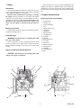
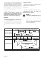
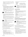
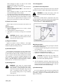
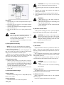
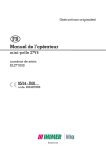
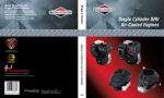
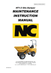
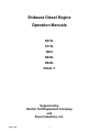
Shibaura Diesel Engine
Operation Manuals
E673L
S773L
N843
N843L
N844L
N844L-T
Supported by
Hustler Turf Equipment Company
and
Excel Industries, Inc.
109821_0508
1
2
109821_0508
FOREWORD
The IHI Shibaura Machinery Corporation (ISM) industrial diesel engines are a product of ISM's long years of experience,
advanced technology. Shibaura takes great pride in the superior durability and operating economy of these engines.
In order to get the fullest use and benefit from your industrial engine, it is important that you operate and maintain it correctly.
This Manual is designed to help you do this.
Please read this Manual carefully and follow its operating and maintenance recommendations. This will ensure many years of
trouble-free and economical engine operation.
Should your engine require servicing, please contact your nearest Authorized Hustler Turf Dealer. He knows your engine best
and is ready to meet your needs.
All information, illustrations, and specifications contained in this Manual are based on the latest product information available
at the time of publication.
Shibaura reserves the right to make changes in this Manual at any time without prior notice.
CALIFORNIA
Proposition 65 Warning
Diesel engine exhaust and some of its constituents are known to the State of California to cause cancer, birth defects, and other
reproductive harm.
Battery posts, terminals and related accessories contain lead and lead compounds, chemicals known to the State of California
to cause cancer and birth defects or other reproductive harm. Wash hands after handling.
109821_0508
3
FEDERAL and CALIFORNIA EMISSIONS WARRANTY
WARRANTY STATEMENT
IHI Shibaura Machinery Corporation (ISM) warrants that your 2004 and later non-road diesel engine was designed, built and
equipped to conform to applicable U.S. Environmental Protection Agency (EPA) and California Air Resources Board (CARB)
regulations and is free from defects in materials and workmanship which cause it to fail to conform with such regulations, for the
following period of operation:
● For a period of two (2) years or 1,500 hours of operation, whichever occurs first, after the date of delivery to the initial
retail owner of any variable speed non-road diesel engine rated at less than 19kW (25hp) and any constant-speed nonroad diesel engine rated at less than 37 kW (50hp) with rated speed greater than or equal to 3,000 min -1.
● For a period of five (5) years or 3,000 hours of operation, whichever occurs first, after the date of delivery to the initial
owner for all other non-road diesel engines.
WARRANTY INFORMATION
The model year, class of diesel engine, and emission application for your engine are identified on the emission control information label affixed to the right hand side of your engine's timing gear case.
Any emission control system parts that are proven defective during normal use will be repaired or replaced during the warranty period.
The warranty repair or replacement will be performed by any Authorized Hustler Turf Dealer or the distributor of the original
equipment manufacturer, with no charge for parts or labor (including diagnosis).
As the engine owner, you are responsible to perform all the required maintenance listed in your owner's manual.
ISM will not deny an emission warranty claim solely because you have no record of maintenance; however, a claim may be
denied if your failure to perform maintenance resulted in the failure of a warranted part. Receipts covering regular maintenance
should be retained in the event of questions and these receipts should be passed on to each subsequent owner of the engine.
It is recommended that replacement parts used for maintenance or repairs be ISM Service Parts to maintain the quality originally designed into your emission certified engine. The use of non-ISM parts does not invalidate the warranty on other components unless the use of such parts causes damage to warranted parts.
ISM wishes to assure that the emission control systems warranty is being properly administered. If you believe you have not
received the service to which you are entitled to under this warranty, you should contact your Authorized Hustler Turf Distributor.
EXCEPTIONS
Please note that Emission Warranty does not cover the following:
1. Diagnosis or inspection expenses that do not result in eligible claim.
2. Consequential damage such as loss of time, inconvenience, loss of use of the engine or equipment.
3. Replacement parts used for required maintenance.
4. Conditions resulting from tampering, misuse, abuse, improper adjustment, engine alteration, use of add-on or modified
parts, use of replacement parts that are not the same in performance and durability as the approved parts, accident, failure to
use recommended fuel or oil, use of unapproved fuel or oil additives, or not performing required maintenance.
5. Damages or repair costs caused by the Owner's unreasonable delay in making the engine available for inspection and repair.
6. Replacement parts used for required or scheduled maintenance.
PARTS COVERED
This emission control system warranty applies to the following emission control parts.
• Fuel Injection Pump
• Fuel Injectors
• Intake Manifold
• Exhaust Manifold Turbocharger (if equipped)
• Positive Crankcase Ventilation system parts (including PCV Valve and Oil Filler Cap)
4
109821_0508
TABLE OF CONTENTS
Safety . . . . . . . . . . . . . . . . . . . . . . . . . . . . . . . . . . . . . . . . . . . . . . . . . . . . .6
Engine external views
Engine main parts nomenclature . . . . . . . . . . . . . . . . . . . . . . . . . . . . . . . .6
General information
3.1
Engine data and specifications. . . . . . . . . . . . . . . . . . . . . . . . .7
ISM engine after service . . . . . . . . . . . . . . . . . . . . . . . . . . . . . . . . . . . . . .7
Fuel, lubricant and coolant
5.1
Fuel. . . . . . . . . . . . . . . . . . . . . . . . . . . . . . . . . . . . . . . . . . . . . .8
5.2
Lubricant. . . . . . . . . . . . . . . . . . . . . . . . . . . . . . . . . . . . . . . . . .9
5.3
Coolant . . . . . . . . . . . . . . . . . . . . . . . . . . . . . . . . . . . . . . . . . .10
Engine operation . . . . . . . . . . . . . . . . . . . . . . . . . . . . . . . . . . . . . . . . . . .10
6.1
Check before operation . . . . . . . . . . . . . . . . . . . . . . . . . . . . .10
6.2
Engine starting . . . . . . . . . . . . . . . . . . . . . . . . . . . . . . . . . . . .12
6.3
Check and operation after the engine start-up . . . . . . . . . . . .13
6.4
Precautions during engine operation . . . . . . . . . . . . . . . . . . .13
6.5
Engine stopping . . . . . . . . . . . . . . . . . . . . . . . . . . . . . . . . . . .15
6.6
Run-in (break-in) for new engine . . . . . . . . . . . . . . . . . . . . . .15
6.7
Engine care for over cooling . . . . . . . . . . . . . . . . . . . . . . . . . .15
6.8
Starting the engine after being left
unused for a long period of time . . . . . . . . . . . . . . . . . . . . . . .15
Periodic inspection and maintenance
7.1
Lubricating system . . . . . . . . . . . . . . . . . . . . . . . . . . . . . . . . .15
7.2
Cooling system . . . . . . . . . . . . . . . . . . . . . . . . . . . . . . . . . . . .17
7.3
Fuel system . . . . . . . . . . . . . . . . . . . . . . . . . . . . . . . . . . . . . .18
7.4
Air intake system . . . . . . . . . . . . . . . . . . . . . . . . . . . . . . . . . .19
7.5
Engine electricals . . . . . . . . . . . . . . . . . . . . . . . . . . . . . . . . . .19
7.6
Engine assembly and others . . . . . . . . . . . . . . . . . . . . . . . . .20
Engine care in cold season . . . . . . . . . . . . . . . . . . . . . . . . . . . . . . . . . . .22
8.1
Fuel. . . . . . . . . . . . . . . . . . . . . . . . . . . . . . . . . . . . . . . . . . . . .22
8.2
Coolant . . . . . . . . . . . . . . . . . . . . . . . . . . . . . . . . . . . . . . . . . .22
8.3
Engine oil . . . . . . . . . . . . . . . . . . . . . . . . . . . . . . . . . . . . . . . .22
8-4
Battery . . . . . . . . . . . . . . . . . . . . . . . . . . . . . . . . . . . . . . . . . .22
8-5
Engine starting . . . . . . . . . . . . . . . . . . . . . . . . . . . . . . . . . . . .22
Engine maintenance schedule . . . . . . . . . . . . . . . . . . . . . . . . . . . . . . . . .23
Simple engine troubleshooting . . . . . . . . . . . . . . . . . . . . . . . . . . . . . . . .25
109821_0508
5
1. Safety
In the caution area, we tell you about something that can
damage your engine or equipment. Many times, this damage
would not be covered by your warranty, and it could be costly.
But the caution will tell you what to do to help avoid the damage.
Introduction
This Operation Manual contains the information you will
need to operate the engine correctly. Check that you have the
correct Operation Manual for your engine.
Read the book carefully before operating or servicing
the engine. Incorrect operation or servicing of the engine
could result in personal injury or material damage as well as
damaging the engine itself. If you do not understand or are
uncertain on any operation in this book, contact your
dealer who can explain or demonstrate the procedure for
you.
2. Engine external views
Engine main parts nomenclatures
1. Stop solenoid
2. Oil filler cap
3. Nozzle and holder
4. Fan
5. Engine control lever
6. Oil dipstick
7. Oil sump
8. Injection pump
9. Oil drain plug
10. Flywheel
11. Oil filter
12. Water drain cock
13. Air intake
14. Head cover
15. Exhaust manifold
16. Starting motor
17. Alternator
18. Crankshft pulley
19. Belt
Warning and Caution
In this manual and on the engine you will find the following special warning symbols.
Safety Warnings
WARNING: This means there is something that could
hurt you or other people.
In the warning area, we tell you what the hazard is. Then
we tell you what to do to help avoid or reduce the hazard.
Please read these warnings. If you don't, you or others could
be hurt.
Engine or Equipment Damage Warnings
CAUTION: This means there is something that could
damage your engine or equipment.
2
4
3
13
14
1
12
5
15
16
8
19
11
18
6
10
9
17
7
6
109821_0508
3. General Information
3.1.Engine data and specifications
Model Name
E673L
Engine Type
S773L
N843
N843L
N844L
N844L-T
Four cycle, water-cooled, in-line overhead valve type
Combustion type
No.of cylinder-bore×stroke (mm)
Swirl chamber
3 - 67×72
3 - 77×81
3 - 84×90
3 - 84×100
4 - 84×100
4 - 84×100
Engine displacement (L)
0.761
1.131
1.496
1.662
2.216
2.216
Compression ratio
23.5
23.5
22.5
22.5
22.5
22.5
* Max output
16.5hp/3000
(12.3kW/3000)
18.5hp/3600
(13.8kW/3600)
24.7hp/3000
(18.4kW/3000)
29.1hp/3600
(21.7kW/3600)
29.4hp/2600
(21.9kW/2600)
30.8hp/3600
(23.0kW/3000)
32.6hp/2600
(24.3kW/2600)
34.2hp/3600
(25.5kW/3000)
44.9hp/2600
(33.5kW/2600)
46.3hp/3600
(35.0kW/3000)
54.7hp/2600
(40.8kW/2600)
56.8hp/3600
42.4kW/3000
* Rated output
13.8hp/3000
(10.3kW/3000)
15.4hp/3600
(11.5kW/3600)
23.3hp/3000
(17.4kW/3000)
24.8hp/3600
(18.5kW/3600)
16.6hp/1500
(12.4kW/1500)
19.7hp/1800
(14.7kW/1800)
N/A
N/A
N/A
N/A
25.3hp/1500
(18.9kW/1500)
29.6hp/1800
(22.1kW/1800)
31.1hp/1500
(23.2kW/1500)
37.8hp/1800
(28.2kW/1800)
Overall length (in) (mm)
17.4 (443)
17.8 (453)
21.0 (534)
21.0 (534)
25.1 (637)
25.3 (642)
Overall width (in) (mm)
15.2 (385)
15.1 (384)
18.1 (459)
18.1 (459)
17.8 (453)
20.3 (516)
* Engine
dimension
Overall height (in) (mm)
* Engine dry weight (lbs.) (kg)
21.5 (546)
23.6 (600)
25.9 (657)
27.1 (689)
28.1 (713)
27.5 (698)
165.3 (75)
191.8 (87)
330.7 (150)
352.7 (160)
429.9 (195)
447.5 (203)
1.37 (1.3)
2.00 (1.9)
3.80 (3.6)
3.80 (3.6)
3.28 (3.1)
5.18 (4.9)
8.66 (8.2)
8.66 (8.2)
Direction of rotation
Coolant volume (Engine only) (qt) (L)
Counter clockwise (Look at Flywheel side)
Lubrication method
Lub. Oil volume (qt) (L)
2.85 (2.7)
2.96 (2.8)
Pressurized circulation by trochoid pump
2.85 (2.7)
Specified engine oil (API grade)
6.34 (6.0)
Quality better than CD class(API)
* Alternator (V-A)
12-14
12-15
12-40
* Starting Motor (V-kW)
12-0.8
12-1.7
12-2.0
Specified fuel
SAE NO. 2-D, DIN 51601, BS Class A-1
Governor
Centrifugal all-speed control
NOTE:
1. The specifications above are subject to partial changes without notice.
2. Asterisked (*) items may vary depending on the type of equipment in which the engine is installed.
4. Shibaura Engine Service
(1) Shibaura Engine After Service
Please feel free to contact your Hustler Turf Equipment
Dealer which is authorized by Shibaura for periodic inspection and maintenance.
When ordering service or spare parts always quote the
engine model name and serial number.
(2) Engine Identification
The engine serial number and engine model are stamped
on the front upper right side of the cylinder body.
Model Name
XXXXXXXXXXX
serial no.
3/04
IHI Shibaura Machinery Corporation
Serial Number
109821_0508
7
Assembled Months / Years
5. Fuel, Lubricant & Coolant
Number 1-D and Number 2-D). This blended fuel is usually
called Number 2-D also, but can be used in colder temperatures than Number 2-D fuel which has not been "winterized".
Check with the service station operator to be sure you get the
properly blended fuel.
Note that diesel fuel may foam during a fill-up. This can
cause the automatic pump nozzle to shut off even though your
tank is not full.
5.1 Fuel
(1) Fuel Selection
The following specific characteristics are required for the
diesel fuel.
1. Must be free from minute dust particles.
2. Must have adequate viscosity.
3. Must have high cetane value.
4. Must have high fluidity at low temperature.
5. Must have low sulfur content.
6. Must have little residual carbon.
CAUTION: Do not use home heating oil or gasoline in your diesel engine; either may cause engine
damage.
(3) Handling of the Fuel
Diesel fuels
Applicable Standard
Recommendation
JIS (Japanese Industrial Standard
NO. 2
DIN (Deutsche Industrie Normen)
Din 51601
SAE (Society of Automotive Engineers) Based on SAE-J-313C
NO. 2-D
BS (British Standard)
Based on BS/2869-1970
Fuel containing dust particles or water will cause engine
failure. Therefore, the following notice must be observed.
1. Prevent dust particles or water from entering when filling
the fuel tank.
When fueling is done from an oil drum directly, keep the
drum stationary for a period of time to allow the sediment
to go to the bottom of the drum.
2. Always fully fill the fuel tank. Drain the sedimented particles in the fuel tank frequently by opening the tank
drain and draining the fuel into approved fuel containers.
Class A-1
(4) Water in Fuel
(2) Fuel Requirements
During refueling, it is possible for water (and other contaminants) to be pumped into your fuel tank along with the
diesel fuel. This can happen if a service station does not regularly inspect and clean its fuel tanks, or if a service station
receives contaminated fuel from its supplier(s).
To protect your engine from contaminated fuel, there is a
fuel filter system on the engine or equipment which allows
you to drain excess water.
CAUTION: The fuel injection pump, injector or
other parts of the fuel system and the engine can
be damaged if you use any fuel or fuel additive
other than those specifically recommended by
Shibaura. Such damage is not Shibaura's responsibility, and is not covered by the Warranty. To help
avoid fuel system or engine damage, please be
aware of the following:
Some service stations mix used engine oil with
diesel fuel. Some manufacturers of large diesel
engines allow this; however, for your diesel
engine, do not use diesel fuel which has been contaminated with engine oil. Besides causing engine
damage, such fuel can also affect emission control.
Before using any diesel fuel, check with the service station operator to see if the fuel has been
mixed with engine oil.
Do not use any fuel additive (other than as recommended under "Biocide" in this section). At the
time this manual was printed, no other fuel additive was recommended. (See your authorized
dealer to find out if this has changed.)
WARNING: The water/diesel fuel mixture is
flammable, and could be hot. To help avoid personal injury and/or property damage, do not touch
the fuel coming from the drain valve, and do not
expose the fuel to open flames or sparks.
Be sure you do not overfill the container. Heat
(such as from the engine) can cause the fuel to
expand. If the container is too full, fuel could be
forced out of the container. This could lead to a
fire and the risk of personal injury and/or vehicle
or equipment damage.
(5) Biocides
Your engine is designed to use either Number 1-D or
Number 2-D diesel fuel. However, for better fuel economy,
use Number 2-D diesel fuel whenever possible. At temperatures less than -7°C, (20°F), Number 2-D fuel may pose operating problems (see "Cold Weather Operation" which
follows). At colder temperatures, use Number 1-D fuel (if
available) or use a "winterized" Number 2-D (a blend of
In warm or humid weather, fungus and/or bacteria may
form in diesel fuel if there is water in the fuel.
CAUTION: Fungus or bacteria can cause fuel system damage by plugging the fuel lines, fuel filters
or injector. They can also cause fuel system corrosion.
8
109821_0508
(1) Engine Oil Selection
If fungus or bacteria has caused fuel system problems, you
should have your authorized dealer correct these problems.
Then, use a diesel fuel biocide to sterilize the fuel system (follow the biocide manufacturer's instructions). Biocides are
available from your dealer, service stations, parts stores and
other automotive places. See your authorized dealer for
advice on using biocides in your area and for recommendations on which biocides you should use.
Quality better than CD grade by API classification engine
oil must be used for the Shibaura engines.
(2) Oil Viscosity
Engine oil viscosity largely affect engine startability, performance, oil consumption, speed of wear and occurrence of
seizure, etc.
Using lubricants with viscosity rated according to the
atmospheric temperature is important.
(6) Smoke Suppressants
Because of extensive testing of treated fuel versus
untreated fuel, the use of a smoke suppressant additive is not
recommended because of the greater possibility of stuck rings
and valve failure, resulting from excessive ash deposits.
CAUTION:
1. Using a mixture of different brand or quality oils
will adversely affect the original oil quality; therefore, never mix different brands or different types
of oils.
2. Don't use API, CA, CB grade and reconstituted
engine oil.
3. Engine damage due to improper maintenance, or
using oil of the improper quality and/or viscosity,
is not covered by the warranty.
5.2 Lubricant
The quality of engine oil may largely affect engine performance, startability and engine life.
Use of unsuitable engine oil will result in piston ring, piston and cylinder seizure and accelerate the sliding surface
wear causing increased oil consumption, lowered output and,
finally engine failure. To avoid this, use the specified engine
oil.
ENGINE OIL VISCOSITY GRADE AMBIENT TEMPERATURE
6$(
6$(:
SINGLE GRADE
6$(:
AMBIENT
TEMPERATURE
6$(
᧩᧯᧬ഒ ᧩᧮᧬ഒ ᧩᧭᧱ഒ
᧩᧮᧮ᨂ
(-4F)
᧬ഒ
᧭᧱ഒ
᧮᧱ഒ
᧤᧱ᨂ᧥ ᧤᧯᧮ᨂ᧥᧤᧱᧵ᨂ᧥᧤᧳᧳ᨂ᧥ ᧤᧴᧲ᨂ᧥
6$(:
6$(:
MULTI GRADE
6$(:
FIG-1
109821_0508
᧯᧬ഒ
9
●
5.3 Coolant
Drain oil to the max. oil level if oil level is above the
max. level mark.
● Add oil to the max. oil level if oil level is below the
min. level mark.
3. Also check the sample oil on the dipstick for fouling and
degrees of viscosity.
Use 50/50 mix Ethylene Glycol and water for coolant and
replace it periodically. (Refer to section 8.2)
6. Engine Operation
CAUTION: Oil level check must be made ten or
twenty minutes after the engine has been stopped.
When the oil level check is necessary while the
engine is running, stop the engine and keep it stationary ten or twenty minutes until the oil thoroughly flows down to the oil pan.
Engine Exhaust Gas Caution
(Carbon Monoxide)
WARNING: Do not breathe exhaust gas because
it contains carbon monoxide, which by itself has
no color or odor. Carbon monoxide is a dangerous
gas. It can cause unconsciousness and can be
lethal.
If at any time you think exhaust fumes are entering
the cab, have the cause determined and corrected
as soon as possible. If you must drive under these
conditions, drive only with all windows fully open.
Protect against carbon monoxide entry into the
cab. The best way is to keep the engine exhaust
system, cab and cab ventilation system properly
maintained. We recommend that the exhaust system and cab be inspected by competent technician:
● Each time the vehicle has an oil change.
● Whenever a change is noticed in the sound of
the exhaust system.
● Whenever the exhaust system, underbody or cab
is damaged or becomes corroded.
See the "Maintenance Schedule" in this manual for
parts requiring inspection.
To allow proper operation of your vehicle's ventilation system, keep the air inlet grille clear of
snow, leaves or other obstructions at all times. Do
not run the engine in confined areas (such as
garages or next to building) any more than needed
to move the vehicles or the equipment.
Keep the exhaust tailpipe area clear of snow and
other material to help reduce the buildup of
exhaust gases under the vehicle or the equipment.
This is particularly important when parked in blizzard conditions.
Max. Level
Min. Level
Engine oil replenishment
Changing the oil
1. Before adding engine oil, place the unit on a level surface, then remove the dipstick to provide crankcase ventilation.
2. MODELS E673L, S773L, N844L, N844L-T ONLY
Add engine oil slowly. Pouring the oil too quickly can
result in the oil overflowing into the air breather valve
and then into the air intake manifold. Cranking the
engine with oil in the manifold will severely damage the
engine.
NOTE: If oil has entered the air intake manifold it will be
necessary to clean the oil from the cylinders. To clean the
cylinders, remove the fuel injection nozzles and turning
the engine with the starter until all oil is exhausted.
When changing the engine oil, add the exact amount
specified in the engine owner’s manual.
NOTE: Use CD grade or better by API classification
engine oil.
MODELS N843 & N843L ONLY — Add oil at the oil
fill shown.
When changing the engine oil, add the exact amount
specified in the engine owner’s manual.
Use CD grade or better by API classification engine oil.
3. Wait about fifteen minutes until the oil gets down to the
oil pan. Then check the oil level with a dipstick. A certain
period of time is required before the engine oil completely flows down from the oil filler to the crankcase.
6.1 Check Before Operation
WARNING: For safety's sake, conduct the inspection before start-up with the engine stopped.
(1) Engine Oil Level
1. Place the engine on a level surface.
2. Remove the dipstick from the crankcase, wipe it with a
clean shop towel or cloth.
Insert it fully and remove it gently again.
Check the oil level by the level marks on the dipstick.
The oil level must be between the "Max." level mark and
the "Min." level mark as illustrated.
Take care not to add too much engine oil.
10
109821_0508
1. When the belt is depressed about 5 mm (0.197 in) with
the thumb (about 50 N (11 lb) pressure) at midway
between the fan pulley and alternator pulley, the belt tension is correct.
When the belt tension is too high, it will result in alternator failure.
Also, a loose belt will cause belt slippage which may
result in damaged belt and abnormal noise.
2. Check the belts. Replace them if any damage is found.
Pour oil slowly to prevent
oil from flowing into the
air intake manifold
CAUTION: Replace all belts as a set even when
one is not usable. Single belt of similar size must
not be used as a substitute for a matched belt set.
Otherwise, premature belt wear would result
because of uneven belt length.
Oil Fill
Oil Fill
N843 & N843L
(3) Coolant Level Check
1. The coolant level must be midway between "FULL" and
"LOW" marks of the reserve tank.
Check and see that the level is correct.
When the coolant level is lower than the "LOW" mark,
fill the reserve tank at the filler port, but when the reserve
tank is empty, fill at the radiator filler port.
2. Remove the radiator filler cap, and check the coolant
level.
Fill radiator to 2.54 cm (1”) below the filler cap.
WARNING: Do not remove the radiator filler cap
while the engine is still hot. Allow the engine to
cool and then cover the cap with a cloth, turn it
slowly to gradually release the pressure. Then
remove the cap.
CAUTION: If the engine oil is splashed on the fan
drive belt, it causes belt slippage or slackness;
therefore, take care to avoid it.
WARNING: In adding oil, take care not to spill it.
If you spill oil on engine or equipment, wipe it
properly, or this could lead to a fire and the risk of
personal injury and/or equipment damage.
3. Use only 50/50 anti-freeze and water as a coolant.
(4) Radiator Cap Condition
(2) Fan Belt Check
After the replenishment of the coolant, install the radiator
cap. Make sure the cap is securely installed.
Check the fan belt for tension and abnormalities.
109821_0508
11
(5) Battery Cable Connection
Check the battery cable connections for looseness or corrosion.
A loose cable connection will result in hard engine starting
or insufficient battery charge.
The battery cables must be tightened securely.
Never reverse "+" and "-" terminals when reconnecting
cables.
Even a short period of reverse connection will damage the
electrical parts.
6.2 Engine Starting
(1) Preparation before starting
1. Make sure that all hydraulic control levers etc. on the
equipment are in the “NEUTRAL” position.
2. Insert the key into the key switch.
Turn the key clockwise to “RUN” position and, make
sure that the meters and warning lamps are actuated.
When any abnormality is discovered, turn the key to the
“OFF” position and locate the cause of the abnormality.
(6) Battery Electrolyte Level
The amount of electrolyte in the batteries will be reduced
after repeated discharge and recharge.
Check the electrolyte for the level in the batteries, refill
with distilled water, if necessary.
The battery electrolyte level checking procedure will vary
with battery type. Follow the equipment manufacturer's
instructions.
RUN
CAUTION: Do not replenish with diluted sulfuric
acid in the daily service.
WARNING:
1) When inspecting the battery, be sure to stop the
engine.
2) As sulfuric acid is used as electrolyte, avoid
contact with eyes, hands, clothes, and metals. If it
gets in your eyes, flush with large amounts of
water at once. Then consult a physician immediately.
3) Since batteries produce hydrogen gas, do not
make a spark or use fire near the battery.
4) When handling metal objects near the batteries,
be sure not to contact the battery’s "+" terminal.
As the vehicle body is "-", it may cause a spark or
electrical shock.
5) When disconnecting the terminals, start with the
negative "-" terminal. When connecting them,
connect the negative "-" terminal last.
(2) Pre-heating Procedure
As an engine starting aid, pre-heating is required for cold
engine starting.
1. Turn the starter key clockwise to the “PRE-HEAT” position in order to heat the glow plugs on the engine.
The pre-heating time varies depending on the types of
pre-heating system as follows:
12
109821_0508
●
The exhaust smoke color after engine warming-up and at
no load operation:
Colorless or
light blue . . . . . .Normal (Perfect combustion)
Black color . . . . . . .Abnormal (Imperfect combustion)
White color . . . . . . .Abnormal (Imperfect combustion)
The type with an indicator light, 10 seconds are
required until the indicator light at the instrument panel
goes off.
2. Turn the starter key clockwise to the “START” position
as soon as the indication lamp goes off.
(3) Engine Starting
CAUTION: Engine noise after start-up might be
noisier than that of warmed-up engine and, the
exhaust smoke color also may be blacker than the
normal condition. However, it should normalize
after warm-up.
1. Depress the engine throttle lever or throttle pedal and
turn the starter key clockwise to the “START” position.
The cranking period must not exceed ten seconds.
Continuous starter operation of more than ten seconds
will lead to over discharge of the batteries as well as
starter seizure.
If the engine cannot be started in a one time attempt, wait
at least 30 seconds for their functional recovery, then
repeat the pre-heating and the starting operations.
Leakage in the systems
Check the following items:
1. Oil leaks
Check both sides and bottom of the engine assembly for
oil leaks, paying particular attention to the oil pressure
gauge pipe joint, oil filter and oil pipe joints.
2. Fuel system leaks
Check the fuel injection pump, fuel lines and fuel filter
for leakage.
3. Coolant leaks
Check the radiator and water pump hose connections and
the water drain cocks on the radiator and cylinder blocks
for leakage.
4. Exhaust smoke or exhaust gas leakage
CAUTION: Continuous re-engagement of the
starter to the flywheel ring gear will result in damaged starter pinion gear and flywheel ring gear.
2. If, after repeated attempts, the engine does not start, wait
for a minute or more, then repeat pre-heating and starting
operations.
3. When repeating starting operation, return the key to the
OFF position and then pre-heat and start the engine once
again.
If the engine still will not start, something may be wrong
with the engine. Contact your Authorized Hustler Turf
dealer/service shop if the problem can not be located.
Checking coolant level
The coolant level could drop depending on the equipment
because the mixed air is expelled in about 5 minutes after the
engine started. Let engine cool before removing radiator cap.
Stop the engine, remove radiator cap, and add coolant.
CAUTION: Do not use starting "aids" in the air
intake system. Such aids can cause immediate
engine damage.
WARNING: Hot steam will rush out and you
could get burnt, if the radiator cap is removed
when the engine is hot. Allow engine to cool
before removing radiator cap.
Cover the radiator cap with a thick cloth and
loosen the cap slowly to reduce the pressure, then
remove the cap.
6.3 Check and Operation After Engine Start-up
(1) Engine Warm-up Procedure
Run engine at Low or Middle speed about ten minutes
after the engine has started.
As the lubrication for the entire engine systems will be
done in this warming-up, do not speed up and load it abruptly.
Particularly, observe this in cold season operation.
6.4 Precautions During Engine Operation
During engine operation, always pay attention to the following items if the engine indicates any sign of abnormalities.
(2) Check After the Engine Start-up
(1) Engine Oil Pressure
Check the following items during engine warm-up operation.
1. Engine oil pressure
Check to see if the oil warning lamp is off.
2. Charge condition
Check to see if the charge warning lamp is off.
3. Engine noise and exhaust smoke color
Pay attention to engine noise and, if any abnormal noise
is heard, check the engine to detect the cause.
Check the fuel combustion condition by exhaust smoke
color.
109821_0508
1. When the engine is warmed up at the specified speed, and
the oil warning lamp is off, the oil pressure is normal.
2. When the oil warning lamp is flashing with the increased
engine speed, stop the engine immediately and check the
engine oil level or for an oil leak.
If the engine oil level is within proper operating range
and no leaks are found contact your local Authorized
Hustler Turf dealer/service shop.
13
(2) Coolant Temperature
If no steam or engine coolant can be seen or heard, open
the engine access cover. If the engine coolant is boiling, wait
until it stops before proceeding. Look at the see-through
reserve tank. The engine coolant level should be between the
"MAX" and "MIN" marks on the reserve tank. If necessary,
pour engine coolant into the reserve tank only, never directly
into the radiator. Also, do not check engine coolant level at
the radiator.
Make sure the fan belts are not broken, or off the pulleys,
and that the fan turns when the engine is started.
If the engine coolant level in the reserve tank is low, look
for leaks at the radiator hoses and connections, heater hoses
and connections, radiator, and water pump. If you find major
leaks, or spot other problems that may have caused the engine
to overheat, do not run the engine until these problems have
been corrected. If you do not find a leak or other problem,
carefully add engine coolant to the reserve tank. (Engine
coolant is a mixture of ethylene glycol antifreeze and water.
See "Engine Care in cold season" in Section 8 for the proper
antifreeze and water mixture.)
The engine performance is adversely affected if engine
coolant temperature is too hot or too cold.
The normal coolant temperature is 75 to 90°C (167 to
194°F).
Overheating
WARNING: If the Engine Coolant Temperature
Gage shows an overheat condition or you have
other reason to suspect the engine may be overheating, continued operation of the engine (other
than as spelled out here) even for a short period of
time may result in a fire and the risk of personal
injury and severe equipment damage.
If you see or hear escaping steam or have other reason to
suspect there is a serious overheat condition, stop and park the
equipment as soon as it is safe to do so and then turn off the
engine immediately and get out of the equipment.
The engine cooling system may overheat if the engine
coolant level is too low, if there is a sudden loss of engine
coolant (such as hose splitting), or if other problems occur. It
may also temporarily overheat during severe operating condition such as:
1. Climbing a long hill on a hot day.
2. Stopping after high rpm.
If the Engine Coolant Temperature Gage shows an overheat condition, or you have reason to suspect the engine may
be overheating, take the following steps:
1. If your air conditioner (if equipped) is on, turn it off. And
turn on the heater.
2. Don't turn off your engine.
3. With the transmission in Neutral, increase the engine
speed to about one-half full operating speed or 1200
RPM, maximum. Bring the idle speed back to normal
after five minutes.
If the engine coolant temperature does not start to drop
within a minute or two:
4. Let the engine run at normal idle speed for two or three
minutes. If the engine coolant temperature does not start
to drop, turn off the engine and get out of the equipment
then proceed as follows:
WARNING: To help avoid being burned, do not
spill antifreeze or engine coolant on the exhaust
system or hot engine parts. Under some conditions the ethylene glycol in engine coolant is combustible.
If the engine coolant level in the reserve tank is at the correct level but there is still an indication on the instrument
panel of an overheat condition:
You must let the engine cool first. You may then add
engine coolant directly to the radiator.
Once the Engine Coolant Temperature Gauge no longer
indicates an overheat condition, you can resume operating at a
reduced speed. Return to normal operating after about ten
minutes if the gage pointer does not again show an overheat
condition.
If no cause for the overheat condition was found, see a
qualified service technician.
Overcooling
The engine operation at low coolant temperature will not
only increase the oil and fuel consumption but also will lead
to premature parts wear which may result in engine failure.
WARNING: To help avoid being burned 1. Do not open the engine access cover if you see
or hear steam or engine coolant escaping from the
engine compartment. Wait until no steam or
engine coolant can be seen or heard before opening the engine cover.
2. Do not remove the radiator cap or engine coolant reserve tank cap if the engine coolant in the
tank is boiling. Also do not remove the radiator
cap while the engine and radiator are still hot.
Scalding fluid and steam can be blown out under
pressure if either cap is taken off too soon.
(3) Engine Hour meter (Engine Operation Hour Indicating) (If so equipped)
This meter indicates the engine operation hours. Make
sure that the meter is always working during engine operation.
Periodic engine maintenance is scheduled based on operating hours indicated on the hourmeter.
(4) Liquid and Exhaust Leakages
Check for lubricant, fuel, coolant and exhaust leaks.
14
109821_0508
6.8 Starting the Engine After Being Left Unused For
A Long Period of Time
(5) Abnormal Engine Noise
Pay attention to the noise from the engine or other related
parts, confirming normal operating noise.
When the equipment is left unused for "more than three
months" without running the engine, conduct a thorough
inspection of the vehicle before starting the engine.
After starting the engine, be sure to warm it up for more
than ten minutes at idling.
(6) Check the Exhaust Color
Check exhaust color as listed in Section 6.3(2)3.
(7) Electrical System
7. Periodic Inspection and Maintenance
Don't turn the key to the “OFF” position while engine is
under load or at full rpm. This may cause electrical parts damage. See Section 6.5.
7.1 LUBRICATING SYSTEM
Servicing of the engine oil or the oil filter element will
affect the engine performance as well as the engine life.
Change the engine oil and the oil filter element periodically with Shibaura or equivalent filter and oil of correct
grade and viscosity. (Refer to 5.2 Lubricant on page 9.)
6.5 Engine Stopping
1. Make sure that all of the control levers on the equipment
are in NEUTRAL position.
2. Before stopping the engine, cool down the engine by
operating it at low idle speed about three minutes.
With the engine at low idle, check the engine noise and
the engine oil pressure for abnormalities.
In the turbocharged engine, if the engine is stopped
instantaneously, a dry condition produced by high temperature will take place in the turbocharger rotating parts
which may cause lack of lubrication. This will result in
turbocharger failure.
3. Turn the starter key switch to the “OFF” position.
(1) Engine Oil and Oil Filter Element Change
Always change the oil filter when changing the engine oil.
Follow the change schedule shown below.
Change interval
Engine Oil
Initial 50 hours . . . . . . . . . . . . . . . . All Models
Every 100 operating hours . . . . . . All Models
Oil Filter Element
Initial 50 hours . . . . . . . . . . . . . . . . All Models
Every 200 operating hours . . . . . . All Models
CAUTION: Leaving the starter key switch in the
“RUN” position for a long period of time after the
engine has been stopped, will discharge the battery.
WARNING: To help avoid being burned, do not
drain oil while the engine is still hot.
6.6 Run-In (Break-In) For New Engines
1. Clean the area around the oil filler cap. Remove the filler
cap.
2. Remove the oil pan drain plug and drain the engine oil
completely.
It is advisable that draining be done while the engine is
warm, to minimize the draining time.
Your Shibaura engine is carefully tested and adjusted in
the factory, however, further, thorough run-in (i.e. break-in)
operation is necessary.
Operating a new engine under extreme loads and/or high
RPM’s, reduces lubrication, resulting in abnormal wear or
engine seizure. Avoid operating the engine under these conditions for the first 100 hours. Observe the following procedures on new engines:
1. Warm up the engine to operating temperature. During
this time do not race the engine.
2. Also do not operate the engine with rapid acceleration,
rapid machine starting and continuous high speed operation.
Oil
6.7 Engine Over-Cooling (Below Normal Operating
Temperature)
Engine over-cooling can cause premature wear and
increased fuel consumption. When the coolant temperature
does not reach 75 to 90°C (167 to 194°F) indefinitely, partially block the radiator to attain the proper operating temperature.
109821_0508
15
CAUTION: Drain the used engine oil into an
approved oil container. Dispose of used oil properly.
Pour oil slowly to prevent
oil from flowing into the
air intake manifold
2
Oil Fill
1
1.
2.
3.
4.
4
Oil filter
Oil filler cap
Oil sump
Drain plug
3
Oil filter element removal
Use a filter wrench to remove the cartridge type oil filter.
Oil filter
Oil Fill
N843 & N843L
Loosen
Tighten
Oil filter element installation
1. Apply light coat of engine oil to the O-ring.
2. Turn in new cartridge until its sealed face comes in contact with the O-ring.
3. Use a filter wrench to tighten the cartridge another 3/4 of
a turn.
Engine oil refilling
1. Reinstall the drain plugs. Remove the oil dipstick from
the engine to allow air to escape.
2. MODELS E673L, S773L, N844L, N844L-T ONLY
Add engine oil slowly. Pouring the oil too quickly can
result in the oil overflowing into the air breather valve
and then into the air intake manifold. Cranking the
engine with oil in the manifold will severely damage the
engine.
NOTE: If oil has entered the air intake manifold it will be
necessary to clean the oil from the cylinders. To clean the
cylinders, remove the fuel injection nozzles and turning
the engine with the starter until all oil is exhausted.
16
109821_0508
7.2 Cooling System
When changing the engine oil, add the exact amount
specified in the engine owner’s manual.
NOTE: Use CD grade or better by API classification
engine oil.
MODELS N843 & N843L ONLY — Add oil at the oil
fill shown.
When changing the engine oil, add the exact amount
specified in the engine owner’s manual.
Use CD grade or better by API classification engine oil.
3. Wait about fifteen minutes until the oil gets down to the
oil pan. Then check the oil level with a dipstick. A certain
period of time is required before the engine oil completely flows down from the oil filler to the crankcase.
(1) Fan Belt Tension Adjustment
Adjust fan belt tension when belt becomes loose and when
the belts are replaced. (Refer to Belt Tension section below)
WARNING: To help avoid injury, check and
adjust fan belt tension with engine stopped.
Belt tension
Belt tension is normal when it is depressed 5 mm (0.197
in) with the thumb at the midway between the fan pulley and
alternator pulley. (about 50 N (11 lb) depressing force.)
Fan belt slackness : About 5 mm (0.197 in)
(2) Check For Oil Leaks
Idle the engine to raise the oil pressure, then check for oil
leakage.
Oil level recheck
1. Stop the engine and allow the oil to drain to bottom
(approx. 20 minutes).
2. Use the dipstick to recheck the oil level.
3. Add engine oil, if necessary, to bring level to maximum
level.
CAUTION: When the engine is started, the oil
level will slightly drop from the initial level as the
oil fills into the entire oil circuit.
(3) Engine Oil Additives
Engine oils contain a variety of additives. Your engine
should not need any extra additives if you use the recommended oil quality and change intervals.
Adjusting procedure
Belt tension adjustment is made by pivoting the alternator
at the alternator mounting bolt.
1. Loosen the alternator adjusting plate bolt and the alternator mounting bolt.
2. Pivot the alternator at the mounting bolt toward the
engine left or right hand side as required.
3. Tighten the mounting bolt and the adjusting bolt.
(4) Used Oil Disposal
Do not dispose of used engine oil (or any other oil) in a
careless manner such as pouring it on the ground, into sewers,
or into streams or bodies of water. Instead, recycle it by taking it to a used oil collection facility which may be found in
your community. If you have a problem disposing of your
used oil, it is suggested that you contact your dealer or service
station. (This also applies to diesel fuel which is contaminated with water. See "Diesel Fuel" in Section 1.)
CAUTION: Belt tension may vary slightly after
the alternator is tightened. Therefore, recheck the
belt tension after tightening the bolts.
4. After the adjustment, operate the engine about five minutes at a low idle speed, stop engine and recheck the belt
tension particularly when installing new belts. Belt tension may vary due to the initial belt seating.
(5) Used Engine Oil
WARNING: Used engine oil contains harmful
contaminants that have caused skin cancer in laboratory animals. Avoid prolonged skin contact.
Clean skin and nails thoroughly using soap and
water - not mineral oil, fuels, or solvents. Launder or discard clothing, shoes, or rags containing
used engine oil.
(2) Fan Belt Change
Use of a low quality fan belt will result in premature belt
wear or belt elongation leading to engine damage such as
overheating. Therefore use of Shibaura genuine fan belt is
highly recommended.
Discard used engine oil and other oil properly.
109821_0508
17
Loosen
Filling with coolant
1. Close or tighten the coolant drain plug.
Using a 50/50 mixture of Ethylene Glycol and water
(Refer to section 8.2) fill the radiator with the coolant
until the level comes up to the filler port neck.
2. Fill gradually to prevent air entry.
Coolant volume (Engine only) :
Refer to "Main Data Specifications"
3. After filling operate the engine about five minutes at a
low idle speed to purge the air from the system. The
coolant level will drop.
Stop the engine and refill with the coolant.
Alternator
(3) Coolant Change
The coolant must be changed at intervals of 6 months.
Degraded or dirty coolant will lead to engine overheating.
Coolant draining
1. Remove the radiator cap.
Open the drain cock at the radiator lower part to drain the
coolant from the radiator.
(4) Cleaning Outside of Radiator
Mud or dried grass caught between radiator fins will block
the air flow, resulting in lower cooling efficiency.
Clean the radiator fins with compressed air.
For the cleaning interval, refer to the instruction manual
prepared by the equipment manufacturer.
If the fins are clogged, however, clean them at any time. If
the fins are deformed, repair or replace the radiator.
WARNING: Never remove the radiator filler cap
while the engine is still hot.
Allow the engine to cool before removing the radiator cap.
Cover the cap with a cloth, then turn it slowly to
release the internal pressure.
(5) Cooling System Circuit Cleaning
2. Drain the coolant from the engine by loosening the water
drain cock on the right hand of cylinder body.
When the cooling system is fouled with water scale or
sludge particles, cooling efficiency will be reduced.
Periodically flush the system with a cleaner.
Cooling system cleaning interval; Every 12 months.
7.3 Fuel System
The fuel injection pump and fuel injection nozzles are precisely manufactured, and therefore, using fuel which contains
water or dust particles will result in either injection pump
plunger seizure or injection nozzle seizure. A fouled fuel filter
element will lead to decreased engine output.
Perform inspection and maintenance periodically as follows:
Water
Drain
Cock
(1) Removal of Water from the Fuel
If the water reaches the fuel filter element bottom, follow
the procedure below to drain the water.
NOTE: Does not apply to Hustler Diesel Z equipment.
18
109821_0508
CAUTION: If the cup is removed without turning
the lever as instructed, the fuel may flow out.
2. Loosen the ring nut, remove the cup, and take out the element.
3. Clean the cup, install a new element, and install new
packing on the ring nut.
4. Tighten the cup to the body securely with the ring nut.
5. After installation, turn the fuel filter lever to the open
position.
WARNING:
1. With the fuel lever in the “OFF” position, the
engine cannot be started.
2. Be careful not to spill fuel on surrounding areas
when removing the fuel cap.
3. After changing the fuel filter element bleed the
air from the system.
Procedure:
1. Turn the fuel lever to the closed position until it stops to
shut off the fuel.
2. Loosen the ring nut, remove the cup together with the
element, and drain the fuel.
3. Clean the cup, install the element and tighten to the filter
body with the ring nut.
4. Turn the fuel filter lever to the open position until it
stops.
(4) Governor Control Seals
As the governor (timing gear case) is precisely adjusted,
most of the controls are sealed, please do not break them.
CAUTION:
1) If the cup is removed without turning the fuel
filter lever just above, the fuel may flow out.
2) The cartridge and cup contain fuel. Take care
not to spill it during disassembly.
3) Perform fuel system air bleeding after the water
in the fuel is drained.
CAUTION: The warranty of the engine can be
affected if the tamper proof seals on the cylinder
block in back of the timing gear case are broken
during the warranty period by a person who is not
authorized by the manufacturer.
7.4 Air Intake System
(2) Fuel System Air Bleeding
(1) Air Cleaner
NOTE: Does not apply to Hustler Diesel Z equipment.
The entry of air into the fuel system will cause hard engine
starting or engine malfunction.
After servicing the fuel system; such as emptying the fuel
tank, fuel system water removal, and the fuel filter element
change, be sure to bleed the air from the system.
Because of the "automatic air-bleeding system" being
employed, turn the starter switch to the "RUN" position and
activate the "electromagnetic pump" to bleed the air.
Engine performance and life vary with the air intake conditions. A dirty air cleaner element reduces the amount of
intake air, causing reduced engine output and/or a poor running engine.
Also, a damaged element leads to wear of cylinders and
valves, resulting in increased oil consumption, reduced output
and shortened engine life.
Replace the air cleaner element annually or if the air
restriction indicator shows that the element needs replaced.
Air bleeding procedure:
1. When the "starter switch" is set to the "Drive" (ON) position to activate the electromagnetic pump, fuel is forcibly
sent to the fuel valve of the injection pump and further to
the leak-off pipe of each nozzle holder, where air in the
fuel leaks off automatically to the fuel tank.
2. Start the engine and check the fuel system for fuel entering the tank.
CAUTION:
1. Change the element, if element damage is
found.
2. Make sure the air filter seals when reassembling
the air cleaner.
7.5 Engine Electrical
The Shibaura engine uses a 12 volt system and a negative
grounding type for the electrical system.
(3) Fuel Filter Element Change
Change interval
Fuel filter element change interval : Every 200 operating
hours or every season.
(1) Battery Servicing
Battery maintenance schedules will vary with equipment
and battery types.
Follow the equipment manufacturer's instructions.
Change procedure
1. Turn the fuel filter lever to the closed position.
109821_0508
19
Follow the equipment manufacturer's recommendation for
intervals.
Loose connections will cause hard engine starting or insufficient battery charging.
If the terminals are excessively corroded, disconnect the
battery cables and polish them with a wire brush or sandpaper.
Never reverse the "+" and "-" terminals when reconnecting
the cables. Even a short period of reverse connection could
damage the electrical system.
Cleaning of Battery
Clean the battery with clean water or tepid water and wipe
them with a dry cloth to remove the water.
Apply a light coat of petroleum jelly or grease to the battery post.
(2) Alternator Servicing
1. The polarity of the alternator is negative grounding type.
When an inverted circuit connection takes place, the circuit will be in short circuit instantaneously resulting in
alternator failure.
2. Do not put water directly on the alternator. Entry of
water into the alternator leads to electrolyte corrosion
causing an alternator failure.
Use caution when cleaning the engine.
3. Disconnect the battery prior to charging with an external
charger.
Specific gravity of the batteries
The battery charge condition is judged by the electrolyte
specific gravity measurement.
Periodically measure the electrolyte gravity of the batteries.
For the internal check follow the equipment manufacturer's standard.
The relationship between the electrolyte specific gravity
and the battery conditions are as follows:
(3) Wiring Connections
Electrolyte Specific Gravity
Battery Conditions
Over 1.300
Over 100%
(Over charged)
1.290 - 1.270
100%
7.6 Engine Assembly and Others
1.260 - 1.240
75%
Below 1.230
Below 50%
(Insufficiently charged)
For continued trouble free engine operation over a long
period of time, the servicing items need a skilled maintenance
technician, therefore, consult your dealer on the following
procedures.
Check all of the electrical wiring for loose connections and
damage.
CAUTION: The battery electrolyte is sulfuric
acid. Prevent contact of electrolyte with skin and
clothes. If this occurs rinse affected area in clean
water.
(1) Fuel Injection Nozzle
Use an injection nozzle tester check the static injection
starting pressure and the fuel spray conditions.
Injection nozzle pressure test interval : Every 1000 operation hours.
When the injection starting pressure is too high or too low
or the fuel spray pattern is improper, an abnormal fuel combustion takes place in the engine leading to lowered output
and blackish exhaust smoke. Further, it can cause a piston
seizure or damage etc. In such cases, the injection nozzle test
or the nozzle replacement is required.
Injection starting pressure …… Refer to the main data and
specifications.
Specific Gravity Conversion
The specified electrolyte temperature for the gravity measurement is 20°C (68°F).
Measure the electrolyte temperature and use the following
formula for conversion.
S20 = St + 0.0007 (t - 20)
S20 ; gravity at 20°
St ; gravity measured
t ; electrolyte temperature when measured
WARNING: When using a nozzle tester, keep
clear of nozzle end. Fuel oil under high pressure
can cause serious injury
Battery Terminal Connections
Periodically, check the battery terminals for loose connection and corrosion.
20
109821_0508
Then measure and adjust the clearance of the other
valves.
Faulty
Good
Cylinder No.
1
2
Valve arrangement
I
E I
When No. 1 cylinder is at TDC
in the compression stroke
X X X
With the crankshaft rotated
360° in normal direction from
above
3
E I
4
E I
E
X
X X
X X
(2) Valve Clearance Adjustment
I: Inlet E: Exhaust
The valve clearance must be adjusted every 1000 operating hours, or whenever the valve rocker is abnormally noisy,
or if there is an engine malfunction and the fuel system is
working properly.
Valve clearance : 0.20 mm (0.008 in) (When the engine is
cold.)
Adjustment Procedure
1. Bring No. 1 cylinder to the top dead center in the compression stroke by aligning the top mark of the crank pulley with top mark of the timing gear case.
2. Remove the cylinder cover and turn the crankshaft in the
forward and backward directions.
If the inlet and exhaust valves of No. 1 cylinder do not
move at this time, No. 1 cylinder is at the top dead center.
When the valves move, give another full turn to the
crankshaft and align the top mark of the crank pulley
with the TOP mark of the timing gear case.
TOP Mark
Model:E673L, N843, N843L
3) Using the table below reference position of #1 piston and
adjust as necessary, measure and adjust the clearance of
the valves.
4) On completion of the valve clearance adjustment in step
3 above, realign mark as in step 1 above by rotating the
crankshaft one complete revolution.
Then measure and adjust the clearance of the remaining
unadjusted valves.
Cylinder No.
1
2
Valve arrangement
I
E
When No. 1 cylinder is at TDC in
the compression stroke
X
X
With the crankshaft rotated 360° in
normal direction from above
I
X
Adjust screw
Valve
clearance
3
E
I
X
X
E
(3) Adjustment of Injection Timing
The injection timing should not be readjusted. Refer to
Engine Service Manual.
X
(4) Cylinder Compression Pressure Measurement
The cylinder compression pressure measurement should
be done every 2000 operation hours, or whenever the engine
output is reduced.
Compression pressure: 2.94 Mpa (426 psi)
Test condition:
Cranking speed 200 rpm
Coolant temperature 75°C (167°F)
Repair the engine and/or replace parts if compression pressure is lower than 2.45 Mpa (355 psi)
I: Inlet E: Exhaust
Model:N844L, N844L-T
3) Using the table below reference position of #1 piston and
adjust as necessary, measure and adjust the clearance of
the valves.
4) On completion of the valve clearance adjustment in step 3
above, realign mark as in step 1 above by rotating the
crankshaft one complete revolution.
109821_0508
21
(5) Starter and Alternator Servicing
Service the starter and alternator every 1000 hours of operation. Do the following:
1. Starter commutator cleaning
2. Alternator slip ring cleaning
3. Carbon brushes and the brush contact check
components of the cooling system and because of
its low boiling point.
2. High silicate antifreeze is not recommended
because it could cause serious silica gelation problems.
3. Usage and mixing ratio etc. should be followed
to the antifreeze manufacture's recommendations.
(6) Radiator Pressurization Valve Check
A pressurization valve is incorporated in the radiator cap
assembly. Check the valve actuating pressure with a radiator
pressure tester. For the pressurization valve actuating pressure and the check interval, follow the equipment manufacturer's standards.
8.3 Engine Oil
8. Engine Care During Cold Season
Engine oil viscosity largely affects engine startability, so
the use of lubricant with selected viscosity according to the
atmospheric temperature is important. (Refer to page 9)
At low atmospheric temperature, engine oil viscosity will
increase to cause hard engine starting.
8.1 Fuel
8.4 Battery
(1) Fuel Selection
1. Make sure batteries are completely charged during cold
weather.
As the discharge current from the battery is more
demanding in cold engine starting, it takes a comparatively longer time to recharge the batteries than tit would
after normal engine starting.
An insufficiently charged battery is more susceptible to
freezing.
Pay attention to keep the battery charged during the cold
season
2. Check and fill the battery with distilled water before
engine operation.
If done after the engine has already been in an operation,
the distilled water will not mix with the original electrolyte, allowing the danger of freezing distilled water
remaining in the upper part of the battery cell.
In the cold zone, the fuel may gel resulting in hard engine
starting; therefore, select a suitable fuel for these conditions.
Use ASTM 975 No. 2-D fuel if you expect temperature
above - 7°C (20°F).
Use Number 1-D if you expect temperatures below - 7°C
(20°F).
If Number 1-D is not available, a "winterized" blend of 1D and 2-D is available in some areas during the winter
months.
Check with the service station operator to be sure you get
the properly blended fuel.
8.2 Coolant
Where the atmospheric temperature falls below freezing
point, the cooling system should be drained after engine operation, but to eliminate the need for repeated draining and
refilling, the use of anti-freeze solution is highly recommended.
A 50/50 Ethylene glycol base antifreeze/water mix.
(which provides protection to -37°C (-34°F) is recommended for use in these Shibaura diesel engines).
Concentrations over 65% adversely affect freeze protection, heat transfer rates, and silicate stability which may cause
water pump leakage.
Never exceed a 60/40 antifreeze/water mix.
(which provides protection to about -50°C (-58°F).
8.5 Engine Starting
When starting the engine, with temperatures of below 0°C
(32°F), following these procedures:
1. Do the preheating operation before cranking the engine
with the starter.
2. Set the engine throttle lever or pedal to the 1/3 position of
the full lever or pedal stroke.
3. If the engine does not start with the initial cranking, wait
a while to allow the batteries to recover their power and,
reattempt the preheating and the cranking operation.
4. In order to protect the starter, cranking time must be limited to 10 seconds.
5. Rapid and repeated engaging and disengaging of the
starter gear with the flywheel ring gear during an attempt
to start the engine indicates a low battery charge. Disconnect the battery and charge it.
6. In extreme cold temperature engine starting, crank the
engine with the throttle closed and no preheat to prelube
the engine (initial engine oil flow). Then open the throttle
to 1/3 position and preheat to start.
WARNING: Under some conditions the ethylene
glycol in the engine coolant is combustible. To
help avoid being burned when adding engine coolant, do not spill it on the exhaust system or engine
parts that may be hot. If there is any question,
have this service performed by a qualified technician.
CAUTION:
1. Methyl alcohol base antifreeze is not recommended because of its effect on the non-metallic
CAUTION: Do not use starting "aids" in the air
intake system. Such aids can cause immediate
engine damage.
22
109821_0508
9. Engine Maintenance Schedule
When performing the following items, the daily inspection items should also be carried out.
Description of check and Maintenance
Initial
50
Every
100
X
1
Oil level and condition of oil
X
2
Oil leakage check
X
3
Oil pressure warning lamp
X
4
Engine oil replacement
X
5
Oil filter element replacement
X
6
Fuel leakage check
7
Draining water in
fuel filter
Every
200
Every
400
Every
600
Every
1000
X
X
w/water sedimentor
X
8
Fuel filter element replacement
X
9
Injection nozzle check (*)
10
Coolant level and condition check
X
11
Coolant leakage check
X
12
Radiator filler cap fitting condition
X
13
Fan belt tension check
(Replace if necessary)
X
14
Overheat warning lamp
X
15
Coolant replacement
16
Radiator external cleaning
X*
Remarks
See
' EXPLANATION OF MAINTENANCE SHEDULE'
Daily
NO
Yearly per Section 7.2 (5)
X
* This is a recommended maintenance. The failure to perform this maintenance item will not nullify the emission warranty
or limit recall liability prior to the completion engine useful life. Shibaura however, urges that recommended maintenance
service is performed at the indicated intervals.
109821_0508
23
Daily
Description of check and Maintenance
17
Cooling system circuit cleaning
18
Radiator filler cap function check (*)
19
Electrolyte level check
X
20
Battery cleaning
X
21
Battery charge condition
Initial
50
Every
100
Every
200
Every
400
Every
600
Every
1000
Remarks
Yearly
Charge warning
lamp
X
See
' EXPLANATION OF MAINTENANCE SHEDULE'
NO
X
22
Electrolyte gravity check
X
23
Starter and alternator check and cleaning(*)
X
24
Wiring and connection check
X
25
Preheating condition check
26
Air cleaner element replacement
27
Engine starting conditions and noise conditions
X
28
Exhaust smoke condition
X
29
Cylinder compression pressure(*)
30
Valve clearance check (*)
X
X
Every 2000 hours
X
NOTE:
1. The service intervals after 1000 operation hours should also be made every 100 operation hours in accordance with this
check and maintenance schedule.
2. When the servicing on the asterisked ( * ) items are necessary, consult the equipment supplier.
Explanation of Maintenance Schedule
The following is a brief explanation of the services listed
in the preceding Engine Maintenance schedule.
1. Oil level and condition of oil
2. Oil leakage check
3. Oil pressure warning lamp
4. Engine oil replacement
5. Oil filter element replacement
6. Fuel leakage check
7. Draining water in fuel filter
8. Fuel filter element replacement
9. Injection nozzle check
10. Coolant level and condition
check
11. Coolant leakage check
12. Radiator filler cap
fitting condition
13. Fan belt tension check
14. Overheat warning lamp
Check that the oil level is between the max. level mark and the min. level mark. Drain
oil to the max. level mark If oil level is above the max. level mark. Add oil to the max.
level mark if oil is below the min. level mark.
Replace any damaged or malfunctioning parts which could cause leakage.
Warning lamp is off while engine running. If it stays on, check and repair the lubrication
system.
Change oil per specified interval.
Change element per specified interval.
Inspect the fuel lines for damage which could cause leakage. Replace any damaged or
malfunctioning parts.
Drain the sedimented water in fuel filter every 100 hours.
Change element every 200 hours.
Check and adjust injection opening pressure and spray condition (This is a recommended maintenance) every 1000 hours.
Check coolant level and add coolant if necessary.
Repair or replace parts as required.
The radiator cap must be installed tightly.
Check and adjust fan belt tension. Look for cracks, fraying and wear.
Coolant temperature is normal at about 75° to 90°C (167° to 194°F)
24
109821_0508
15. Coolant replacement
16. Radiator external
cleaning
17. Cooling system flushing
18. Radiator filling cap function check
19. Electrolyte level check
20. Battery cleaning
21. Battery charge condition
22. Electrolyte gravity check
23. Starter and alternator
check and cleaning
24. Wiring and connection check
25. Preheating condition check
26. Air cleaner element replacement
27. Engine starting condition
and noise condition
28. Exhaust smoke condition
29. Cylinder compression
pressure
30. Valve clearance check
Use 50/50 anti-freeze and water mixture.
According to the equipment manufacture's specification. (reference: every 500 hours)
Flush the cooling system circuit every 2000 hours
Check radiator pressure cap periodically for proper operation according to the equipment manufacturer's specifications. (reference: every 200 hours)
Refill with distilled water if necessary.
Clean the terminals.
Indicator type, the lamp should be off while engine running.Check charging circuit if
the lamp is not off.
Check according to the equipment manufacturer's specifications. (reference: every 200
hours)
Check wear of brush and commutator (every 1000 hours)
Check according to the equipment specifications. (reference: every 1000 hours)
Check preheating condition of the system.
Change element according to the manufacturer's specifications. (reference: every 200
hours) or per restriction indicator.
Check engine stability and noise.
Check exhaust smoke color.
Check every 2000 hours.
Incorrect valve clearance will result in increased engine noise and lower engine output.
Thereby adversely affecting engine performance. Check and adjust every 1000 hours.
10. Simple Engine Troubleshooting
This section contains simple engine troubleshooting
guides. Use this guide to troubleshoot engine problems.
If problem cannot be diagnosed contact your local
Authorized Hustler Turf dealer/service shop.
109821_0508
25
Engine does not start.
Starter does not turn.
Starter turns but engine does not start.
Battery discharged.
Loose cable connections.
Starter or starter switch failure.
Safety relay failure.
No fuel injection.
Engine starts but stalls immediately.
Fuel is injected but engine does not start.
No fuel in the fuel tank.
Clogged fuel filter element or strainer.
Air in the fuel system.
Feed pump malfunction.
Control rack is stuck at no fuel position.
Improper preheating operation.
Glow plug malfunction.
Incorrect injection timing.
Low cylinder compression pressure.
Wrong engine oil viscosity.
Air in the fuel system.
Improper start spring.
26
109821_0508
Unstable engine running
Unstable low idling
Too high low idling speed.
Incorrect control lever adjustment.
Crack in injection pipe.
Injection nozzle failure.
Engine stop lever restricted at stop position.
Uneven compression pressure between cylinders.
Engine hunting in medium speed range.
Incorrect control lever adjustment.
Governor internal malfunction.
Malfunction in engine at high speed range.
Governor spring deteriorated.
Insufficient fuel supply.
Air in the fuel system.
Clogged fuel filter element.
Uneven fuel injection amount
between plungers.
Deteriorated governor spring.
Incorrect valve clearance adjustment.
Deteriorated valve spring.
Engine speed will not slow
Engine control restriction or seizure.
Engine overheat.
Cooling system defect.
Improper servicing.
Insufficient coolant amount.
Fan belt slippage.
Thermostat malfunction.
Radiator filler cap malfunction.
Cooling system internally fouled.
Radiator clogging.
109821_0508
Engine over-loaded.
Air cleaner element clogging.
Insufficient ventilation.
Stopped coolant flow
(high concentration of antifreeze, etc.)
27
Low oil pressure
Lack of oil
Improper oil
Oll leakage
Large oil consumption.
Clogged filter and strainer.
High lubricating oil temperature
Wrong selection of
kind and viscosity.
Over heat
Worn bearings and oil pump.
Faulty relief valve.
Lack of power
Incorrect injection pump adjustment.
Poor cylinder compression pressure.
Injection nozzle malfunction,
Cylinder compression pressure leakage.
lncorrect injection pressure adjustment
Incorrect spray condition
Insufficient fuel supply to the injection pump
Lack of fuel in tank
Air mixing in injection pump
Fuel filter clogged
lntake valve clearance
adjustment.
Nozzle holder misalignment
Cylinder bore wear
Insufficient air intake amount
Air cleaner clogging
Intake restriction
Governor malfunction.
Incorrect engine control adjustment
Deteriorated governor spring
Excessive fuel consumption
Fuel leakage
Too much injection amount
Excessive mechanical loads
Injection pump misadjustment.
Damaged packing.
Improper installation or tightening.
109821_0508
28
Condition
Improper color of
engine exhaust
(white or blue)
Improper engine
exhaust (black or
dark gray)
109821_0508
Cause
Remedy
Too much engine oil.
Too low viscosity of engine oil.
Improper fuel.
Improper injection timing.
Engine oil burning or detonation.
Overload.
Clogged air cleaner.
Improper fuel.
Excessive fuel injection.
Improper function of fuel injection
pump.
Clogged fuel filter.
Improper function of engine main
body.
29
Check and adjust the quantity.
Check and change.
Flush & change oil
See dealer
See dealer
Reduce the load
Check and change.
Check and change.
See dealer
See dealer
Clean or replacement element
See dealer
All information, illustrations and specifications contained in this manual are based on the latest product information available at
the time of publication. The right is reserved to make changes at any time without notice.
OPERATION MANUAL (INDUSTRIAL)
E673L
S773L
N843
N843L
N844L
N844L-T
Issued by
IHI Shibaura Machinery Corporation, Ltd.
and
Hustler Turf Equipment
30
109821_0508