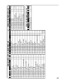
1
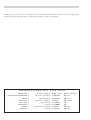
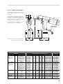
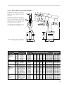
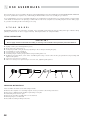
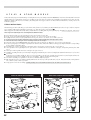
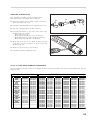
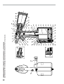
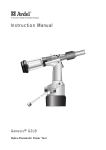
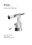
Instruction Manual
PE
TY
07
64
Pass onto user to read and keep for reference
Hydro-Pneumatic Power Tool
0764 type
07640 - 07641 - 07642
AVDEL policy is one of continuous development. Specifications shown in this document may be subject to changes which
may be introduced after publication. For the latest information always consult Avdel.
SPECIFICATIONS
FOR
0764
AIR PRESSURE ■
Minimum - Maximum
FREE AIR VOLUME REQUIRED ■
@ 5.5 bar / 80 lbf/in 2
STROKE ■
07640 Minimum
PULL FORCE ■
CYCLE TIME ■
@ 4.8 bar / 70 lbf/in
2
Approximately
NOISE LEVEL ■
Less than
WEIGHT ■
Without nose equipment
VIBRATION ■
Less than
■
■
■
■
■
■
■
■
TOOL
4.8 - 7 bar
3.8 litres
15.6 mm
6.7 kN
1 second
70 dB(A)
1.5 kg
2.5 m/s
2
■
■
■
■
■
■
■
■
70 - 100 lbf/in 2
.13 ft 3
.625 in
1506 lbf
3.3 lb
8 ft/s 2
CONTENTS
SAFETY
General
2
Specific to 0764 Tool
3
General
4
INTENT OF USE
07640 Tool Dimensions / Selection
4-5
07641 Tool Dimensions / Selection
6
07642 Tool Dimensions / Selection
7
Air Supply
8
Operating Procedure
8
Accessories
9
PUTTING INTO SERVICE
NOSE ASSEMBLIES
07640 Fitting/Servicing/Components
10-11
07641 Fitting/Servicing/Components
12-13
07642 Fitting/Servicing/Components
12-13
Regular Servicing - Service Kit
14-15
Maintenance
15-17
General Assembly & Parts List
18-19
SERVICING
PRIMING
FAULT
Priming Oil Details
20
Priming Procedure
20
Fault Diagnosis Table
21
DIAGNOSIS
1
SAFETY
This instruction manual must be read with particular attention to the following safety rules,
by any person installing, operating, or servicing this tool.
DO NOT USE OUTSIDE THE DESIGN INTENT.
DO NOT USE EQUIPMENT WITH THIS TOOL/MACHINE OTHER THAN THAT
RECOMMENDED AND SUPPLIED BY AVDEL.
ANY MODIFICATION UNDERTAKEN BY THE CUSTOMER TO THE TOOL/MACHINE,
NOSE ASSEMBLIES, ACCESSORIES OR ANY EQUIPMENT SUPPLIED BY AVDEL OR THEIR
REPRESENTATIVES, SHALL BE THE CUSTOMER'S ENTIRE RESPONSIBILITY. AVDEL WILL BE
PLEASED TO ADVISE UPON ANY PROPOSED MODIFICATION.
THE TOOL/MACHINE MUST BE MAINTAINED IN A SAFE WORKING CONDITION AT
ALL TIMES AND EXAMINED AT REGULAR INTERVALS FOR DAMAGE AND FUNCTION BY
TRAINED COMPETENT PERSONNEL. ANY DISMANTLING PROCEDURE SHALL BE
UNDERTAKEN ONLY BY PERSONNEL TRAINED IN AVDEL PROCEDURES. DO NOT DISMANTLE
THIS TOOL/MACHINE WITHOUT PRIOR REFERENCE TO THE MAINTENANCE INSTRUCTIONS.
CONTACT AVDEL WITH YOUR TRAINING REQUIREMENTS.
THE TOOL/MACHINE SHALL AT ALL TIMES BE OPERATED IN ACCORDANCE WITH
RELEVANT HEALTH AND SAFETY LEGISLATION. IN THE U.K. THE “HEALTH AND SAFETY AT
WORK ETC. ACT 1974” APPLIES. ANY QUESTION REGARDING THE CORRECT OPERATION
OF THE TOOL/MACHINE AND OPERATOR SAFETY SHOULD BE DIRECTED TO AVDEL.
THE PRECAUTIONS TO BE OBSERVED WHEN USING THIS TOOL/MACHINE MUST BE
EXPLAINED BY THE CUSTOMER TO ALL OPERATORS.
ALWAYS DISCONNECT THE AIRLINE FROM THE TOOL/MACHINE INLET BEFORE
ATTEMPTING TO ADJUST, FIT OR REMOVE A NOSE ASSEMBLY.
DO NOT OPERATE A TOOL/MACHINE THAT IS DIRECTED TOWARDS ANY PERSON(S).
ALWAYS ADOPT A FIRM FOOTING OR A STABLE POSITION BEFORE OPERATING THE
TOOL/MACHINE.
ENSURE THAT VENT HOLES DO NOT BECOME BLOCKED OR COVERED AND THAT
HOSES ARE ALWAYS IN GOOD CONDITION.
2
In addition to the general safety rules opposite, the following specific safety points must also
be observed:
2
THE OPERATING PRESSURE SHALL NOT EXCEED 7 BAR - 100 LBF/IN .
DO NOT OPERATE THE TOOL WITHOUT FULL NOSE EQUIPMENT IN PLACE.
DO NOT OPERATE THE TOOL UNLESS THE BASE COVER IS FULLY SEATED ON THE
TOOL BASE, ENSURING THAT THE RETAINING RING (ITEM 28 ON GENERAL ASSEMBLY)
IS CORRECTLY INSTALLED.
CARE SHALL BE TAKEN TO ENSURE THAT SPENT STEMS ARE NOT ALLOWED TO
CREATE A HAZARD.
07640 TOOLS MUST BE FITTED WITH AN UNDAMAGED PINTAIL DEFLECTOR OR STEM
CATCHER BEFORE OPERATING.
IF THE 07640 TOOL IS FITTED WITH A PINTAIL DEFLECTOR AND IS USED IN THE
VERTICAL NOSE DOWNWARD POSITION, THE PINTAIL DEFLECTOR SHOULD BE ROTATED
UNTIL THE APERTURE IS FACING AWAY FROM THE OPERATOR AND OTHER PERSON(S)
WORKING IN THE VICINITY.
WHEN USING THE TOOL, THE WEARING OF SAFETY GLASSES IS REQUIRED BOTH BY
THE OPERATOR AND OTHERS IN THE VICINITY TO PROTECT AGAINST RIVET EJECTION,
SHOULD A FASTENER BE PLACED ‘IN AIR’. WE RECOMMEND WEARING GLOVES IF THERE
ARE SHARP EDGES OR CORNERS ON THE APPLICATION.
TAKE CARE TO AVOID ENTANGLEMENT OF LOOSE CLOTHES, TIES, LONG HAIR,
CLEANING RAGS ETC., IN THE MOVING PARTS OF THE TOOL WHICH SHOULD BE KEPT
DRY AND CLEAN FOR BEST POSSIBLE GRIP.
WHEN CARRYING THE TOOL FROM PLACE TO PLACE KEEP HANDS AWAY FROM THE
TRIGGER/LEVER TO AVOID INADVERTENT START UP.
EXCESSIVE CONTACT WITH HYDRAULIC OIL SHOULD BE AVOIDED. TO MINIMIZE THE
POSSIBILITY OF RASHES, CARE SHOULD BE TAKEN TO WASH THOROUGHLY.
3
INTENT
OF USE
The hydro-pneumatic 0764 type tool is designed to place Avdel breakstem rivets at high speed making it ideal for batch or flow-line
assembly in a wide variety of applications throughout all industries.
The 07640 fitted with a stem catcher is the standard tool for which a pintail deflector option is available (see details on page 9). It
is also possible to order the base tool only (part number 07640-00200) which will not be fitted with a nose assembly.
The base tool part number for the other two tools of this type, the 07641 and 07642, is 07641-00200. Differences with the
07640-00200 are on the general assembly and parts lists pages 18 and 19.
07640 TOOL SELECTION
FASTENER
NOSE (see drawing opposite for A & B)
NAME & HEAD
Ø
MATERIAL/DETAIL NOSE TIP TYPE A (mm) B (mm) A (in) B (in) NOSE ASSY PART Nº
1/8"
AVEX
12.7
3.3 .500 .130
07347-03000
Standard
Al. Alloy
Snap head
9.5
12.9 .375 .510
07490-01000
Extended
Al. Alloy
& 120° csk
12.7
3.3 .500 .130
07347-03400
Hd. Forming
Al. Alloy
Steel
head except
12.7
3.3 .500 .130
07347-03200
Standard
5 / 32 "
Al. Alloy
07640-00019
12.7
3.3 .500 .130
07347-03200
Standard
large flange
9.5
11.4 .375 .450
07490-01700
Extended
Al. Alloy
Al. Alloy
only.
12.7
3.3 .500 .130
07347-03500
Hd. Forming
Steel
12.7
3.3 .500 .130
07347-03300
Standard
3 / 16 "
Al. Alloy
12.7
3.3 .500 .130
07347-03300
Standard
Al.Alloy
9.5
10.0 .375 .395
07490-02400
Extended
Al. Alloy
12.7
4.1 .500 .160
07347-03600
Hd. Forming
Steel
12.7
3.3 .500 .130
07381-04800
Standard
Al. Alloy L/flange
19.0
4.1 .750 .160
07490-05000
Standard
Al. Alloy
3mm
12.7
3.3 .500 .130
07347-03100
Standard
3 / 16 "
Al. Alloy & Steel
MONOBOLT
12.7
4.1 .500 .160
07498-04500
Standard
5 / 32 "
Al. Alloy
BULBEX
12.7 11.4 .500 .130
07347-03200
Standard
Al. Alloy
9.5
3.3 .375 .450
07490-01700
Extended
3 / 16 "
Al. Alloy
12.7
3.3 .500 .130
07347-03300
Standard
Al. Alloy
9.5
10.0 .375 .395
07490-02400
Extended
Al. Alloy
4mm
AVSEAL
12.7
4.5 .500 .177
07340-07600
Short
Al. Alloy
5mm
12.7
4.5 .500 .177
07640-02100
Short
Al. Alloy
6mm
12.7
5.3 .500 .208
07640-02200
Short
Al. Alloy
6.5mm
12.7
5.3 .500 .208
07340-08300
Short
Al. Alloy
7mm
12.7
5.3 .500 .208
07640-02400
Short
Al. Alloy
4mm
12.7
6.7 .500 .264
07498-08400
Extended
Al. Alloy
5mm
12.7
6.7 .500 .264
07640-03100
Extended
Al. Alloy
6mm
12.7
7.2 .500 .283
07640-03200
Extended
Al. Alloy
6.5mm
12.7
7.2 .500 .283
07498-09100
Extended
Al. Alloy
7mm
12.7
7.2 .500 .283
07640-03400
Extended
3 / 16 "
Al. Alloy
TLR
12.7
4.1 .500 .160
07498-01600
Standard
1/8"
Stainless Steel
AVINOX II
12.7
3.3 .500 .130
07347-03200
Standard
5 / 32 "
Stainless Steel
12.7
3.3 .500 .130
07381-04700
Standard
3 / 16 "
Stainless Steel
12.7
3.3 .500 .130
07347-03700
Standard
1/8"
St.Steel & Titanium
AVDEL
12.7
3.3 .500 .130
07344-02100
Standard
Al. Alloy
Snap head
12.7
2.5 .500 .100
07344-02300
Standard
Al. Alloy Oversize
100° csk &
12.7
2.5 .500 .100
07344-02900
Standard
5 / 32 " St.Steel & Titanium
120° csk
12.7
2.5 .500 .100
07344-02400
Standard
Al. Alloy
12.7
2.5 .500 .100
07344-02600
Standard
Al. Alloy Oversize
12.7
2.5 .500 .100
07344-03000
Standard
3 / 16 "
Al. Alloy
12.7
2.5 .500 .100
07344-02700
Standard
Al. Alloy Oversize
12.7
2.5 .500 .100
07344-03100
Standard
.
.
4
COMPLETE
TOOL PART Nº
07640-00001
07640-00002
07640-00003
07640-00008
07640-00008
07640-00009
07640-00010
07640-00015
07640-00015
07640-00016
07640-00017
07640-00018
07640-00019
07640-00006
07640-00031
07640-00008
07640-00009
07640-00015
07640-00016
07640-00064
07640-00065
07640-00066
07640-00062
07640-00067
07640-00074
07640-00075
07640-00076
07640-00072
07640-00077
07640-00058
07640-00008
07640-00032
07640-00033
07640-00011
07640-00005
07640-00007
07640-00014
07640-00012
07640-00013
07640-00021
07640-00020
07640 - FIXED NOSE ASSEMBLY
The 07640 is fitted with a fixed straight
nose assembly suitable where access is
unrestricted.
Use the selection chart below and opposite
to select a complete 07640 tool which will
include the correct nose assembly for a
selected fastener. For details of Nose
Assemblies see pages 10 and 11.
23
.91
33
1.30
12°
A
61
2.40
B
87
3.43
110
4.33
‘A’ and ‘B’ dimensions will help you assess
the accessibility of your application.
63
2.48
258
10.16
76
4
FLEXIBLE HOSE
LENGTH 500 (19)
96
3.78
Dimensions shown in bold are millimetres.
Other dimensions are in inches.
92
3.62
113
4.45
07640 TOOL SELECTION (Continued)
FASTENER
NOSE (see drawing opposite for A & B)
NAME & HEAD
Ø
MATERIAL/DETAIL NOSE TIP TYPE A (mm) B (mm) A (in) B (in) NOSE ASSY PART Nº
1/8"
Stainless Steel
STANDARD
12.7
4.7 .500 .187
07498-02400
Standard
Al. Alloy
MBC
12.7
4.7 .500 .187
07498-06700
Standard
Al. Alloy Oversize
Universal Hd
12.7
4.7 .500 .187
07498-07000
Standard
5 / 32 "
Stainless Steel
& 100° csk
12.7
4.7 .500 .187
07498-02500
Standard
Al. Alloy
12.7
4.7 .500 .187
07347-03900
Standard
Al. Alloy Oversize
12.7
4.7 .500 .187
07344-03200
Standard
3 / 16 "
Al. Alloy
12.7
4.7 .500 .187
07347-04000
Standard
Al. Alloy
LOCK CREATOR 1/8 "
12.7
4.7 .500 .187
07498-07600
Standard
Al. Alloy Oversize
MBC
12.7
4.7 .500 .187
07498-07600
Standard
St. Steel
Universal Hd
12.7
4.7 .500 .187
07344-04700
Standard
Hybrid Oversize
& 100° csk
12.7
4.7 .500 .187
07498-07300
Standard
5 / 32 "
Al. Alloy
12.7
4.7 .500 .187
07344-05100
Standard
Al. Alloy Oversize
12.7
4.7 .500 .187
07344-05100
Standard
Stainless Steel
12.7
4.7 .500 .187
07344-04700
Standard
Hybrid Oversize
12.7
4.7 .500 .187
07344-05300
Standard
3/ 16 "
Al. Alloy
12.7
4.7 .500 .187
07498-07800
Standard
Steel
4.3mm
T-LOK
12.7
3.3 .500 .130
07241-07400
Standard
Steel
9.5
10.0 .375 .395
07241-07300
Extended
3/ 16 "
Steel
12.7
07241-07400
3.3 .500 .130
Standard
Steel
9.5
07241-07300
10.0 .375 .395
Extended
5 / 32 "
Steel
AVIBULB
12.7
07381-04700
3.3 .500 .130
Standard
3 / 16 "
Steel
Low profile Hd
12.7
07347-03700
3.3 .500 .130
Standard
1/8"
All Materials
AVDEL SR
12.7
07347-03000
3.3 .500 .130
Standard
5 / 32 "
All Materials
Raised Hd
12.7
07347-03200
3.3 .500 .130
Standard
3 / 16 "
All Materials
120° csk
12.7
07640-06800
3.3 .500 .130
Standard
COMPLETE
TOOL PART Nº
07640-00045
07640-00051
07640-00054
07640-00046
07640-00052
07640-00055
07640-00053
07640-00035
07640-00035
07640-00036
07640-00037
07640-00038
07640-00038
07640-00036
07640-00040
07640-00041
07640-00022
07640-00023
07640-00022
07640-00023
07640-00032
07640-00033
07640-00001
07640-00008
07640-00004
5
07641 - STRAIGHT SWIVEL NOSE ASSEMBLY
The 07641 is fitted with a “straight” swivel
type of nose assembly for use on
applications with restricted access.
It will place all the fasteners listed in the
selection table below. Use this table to
select a complete 07641 tool which will
include the correct nose assembly for a
selected fastener. For details of Nose
Assemblies see pages 12 and 13.
A
20
.79
B
33Ø
1.30Ø
92
3.62
263
10.35
56
2.20
87
3.43
28
1.12
6
.24
360°rotation
about centre line
‘A’ and ‘B’ dimensions will help you assess
the accessibility of your application.
12°
76
4
258
10.16
96
3.78
Dimensions shown in bold are millimetres.
Other dimensions are in inches.
87
3.43
108
4.25
07641 TOOL SELECTION
FASTENER
NOSE (see drawing opposite for A & B)
NAME & HEAD
Ø
MATERIAL/DETAIL NOSE TIP TYPE A (mm) B (mm) A (in) B (in) NOSE ASSY PART Nº
1/8"
Al. Alloy
AVEX
7.87 3.81 .310 .150
07345-03000
Standard
Steel
Snap head
7.87 3.81 .310 .150
07345-03100
Standard
5/32"
Al. Alloy
& 120° csk
7.87 3.81 .310 .150
07345-03100
Standard
Steel
head
7.87 3.81 .310 .150
07345-03200
Standard
3/16"
Al. Alloy
7.87 3.81 .310 .150
07345-03200
Standard
Steel
7.87 4.19 .310 .165
07494-04000
Standard
3/16"
Al. Alloy
BULBEX
7.87 3.81 .310 .150
07345-03200
Standard
Al. Alloy
4mm
AVSEAL
6.35 1.95 .250 .077
07494-06000
Short
Al. Alloy
5mm
7.62 2.00 .300 .079
07494-06100
Short
Al. Alloy
4mm
6.35 4.11 .250 .162
07494-06600
Extended
Al. Alloy
5mm
7.62 4.11 .300 .162
07494-06700
Extended
1/8"
Stainless Steel
AVINOX
7.87 3.81 .310 .150
07345-03100
Standard
5/32"
Stainless Steel
7.87 3.81 .310 .150
07345-03200
Standard
1/8"
St.Steel & Titanium
AVDEL
5.08 3.81 .200 .150
07494-03000
Standard
Al. Alloy
Snap head
5.08 1.17 .200 .046
07345-03300
Standard
Al. Alloy Oversize
100° csk &
5.08 1.17 .200 .046
07494-03600
Standard
5/32" St.Steel & Titanium
120° csk
6.60 0.84 .260 .033
07494-03100
Standard
Al. Alloy
6.60 0.84 .260 .033
07345-03400
Standard
Al. Alloy Oversize
6.60 0.84 .260 .033
07494-03700
Standard
3/16"
Al. Alloy
8.13 0.25 .320 .010
07345-03500
Standard
Al. Alloy Oversize
8.13 0.25 .320 .010
07494-03800
Standard
3/32"
Stainless Steel
5.08 1.27 .200 .050
07494-03400
Standard
1/8"
Al.Alloy & St.Steel
STANDARD
4.75 2.40 .187 .093
07345-04000
Standard
Al. Alloy Oversize
MBC
4.75 2.40 .187 .093
07345-04300
Standard
5/32"
Al.Alloy & St.Steel
Universal Hd
6.35 2.40 .250 .093
07345-04100
Standard
Al.Alloy Oversize
100° csk
6.35 2.40 .250 .093
07345-04400
Standard
3/16"
Al.Alloy
7.92 2.40 .312 .093
07345-04200
Standard
6
COMPLETE
TOOL PART Nº
07641-00004
07641-00005
07641-00005
07641-00006
07641-00006
07641-00036
07641-00006
07641-00064
07641-00065
07641-00074
07641-00075
07641-00005
07641-00006
07641-00024
07641-00014
07641-00017
07641-00025
07641-00015
07641-00018
07641-00016
07641-00019
07641-00023
07641-00051
07641-00054
07641-00052
07641-00055
07641-00053
07642 - RIGHT ANGLE SWIVEL NOSE ASSEMBLY
The 07642 is fitted with a “right angle”
swivel type of nose assembly for use on
applications with no direct access to the
fixing point.
B
20
.79
32
1.26
A
75
97
3.82 2.95
It will place all the fasteners listed in the
selection table below. Use this table to
select a complete 07642 tool which will 33Ø
include the correct nose assembly for a 1.30Ø
selected fastener. For details of Nose
Assemblies see pages 12 and 13.
52
2.05
255
10.04
56
2.20
87
3.43
360°rotation
about centre line
‘A’ and ‘B’ dimensions will help you assess
the accessibility of your application.
28
1.12
12°
76
4
258
10.16
96
3.78
Dimensions shown in bold are millimetres.
Other dimensions are in inches.
87
3.43
108
4.25
07642 TOOL SELECTION
FASTENER
NOSE (see drawing opposite for A & B)
NAME & HEAD
Ø
MATERIAL/DETAIL NOSE TIP TYPE A (mm) B (mm) A (in) B (in) NOSE ASSY PART Nº
1/8"
Al. Alloy
AVEX
7.87 3.81 .310 .150
07346-03000
Standard
Steel
Snap head
7.87 3.81 .310 .150
07346-03100
Standard
5/32"
Al. Alloy
& 120° csk
7.87 3.81 .310 .150
07346-03100
Standard
Steel
head
7.87 3.81 .310 .150
07346-03200
Standard
3/16"
Al. Alloy
7.87 3.81 .310 .150
07346-03200
Standard
Steel
7.87 4.19 .310 .165
07495-03500
Standard
3/16"
Al. Alloy
BULBEX
7.87 3.81 .310 .150
07346-03200
Standard
Al. Alloy
4mm
AVSEAL
6.35 1.95 .250 .077
07495-04000
Short
Al. Alloy
5mm
7.62 2.00 .300 .079
07495-04100
Short
Al. Alloy
4mm
6.35 4.11 .250 .162
07495-04700
Extended
Al. Alloy
5mm
7.62 4.11 .300 .162
07495-04800
Extended
1/8"
Stainless Steel
AVINOX
7.87 3.81 .310 .150
07346-03100
Standard
5/32"
Stainless Steel
7.87 3.81 .310 .150
07346-03200
Standard
1/8"
St.Steel & Titanium
AVDEL
5.08 3.81 .200 .150
07495-03000
Standard
Al. Alloy
Snap head
5.08 1.17 .200 .046
07346-03300
Standard
Al. Alloy Oversize
100° csk &
5.08 1.17 .200 .046
07495-03600
Standard
5/32" St.Steel & Titanium
120° csk
6.60 0.84 .260 .033
07495-03100
Standard
Al. Alloy
6.60 0.84 .260 .033
07346-03400
Standard
Al. Alloy Oversize
6.60 0.84 .260 .033
07495-03700
Standard
3/16"
Al. Alloy
8.13 0.25 .320 .010
07346-03500
Standard
Al. Alloy Oversize
8.13 0.25 .320 .010
07495-03800
Standard
3/32"
Stainless Steel
5.08 1.27 .200 .050
07495-03400
Standard
1/8"
Al.Alloy & St.Steel
STANDARD
4.75 2.40 .187 .093
07346-04000
Standard
Al. Alloy Oversize
MBC
4.75 2.40 .187 .093
07346-04300
Standard
5/32"
Al.Alloy & St.Steel
Universal Hd
6.35 2.40 .250 .093
07346-04100
Standard
Al.Alloy Oversize
100° csk
6.35 2.40 .250 .093
07346-04400
Standard
3/16"
Al.Alloy
7.92 2.40 .312 .093
07346-04200
Standard
COMPLETE
TOOL PART Nº
07642-00004
07642-00005
07642-00005
07642-00006
07642-00006
07642-00036
07642-00006
07642-00064
07642-00065
07642-00074
07642-00075
07642-00005
07642-00006
07642-00024
07642-00014
07642-00017
07642-00025
07642-00015
07642-00018
07642-00016
07642-00019
07642-00023
07642-00051
07642-00054
07642-00052
07642-00055
07642-00053
7
PUTTING
AIR
INTO SERVICE
SUPPLY
All tools are operated with compressed air at an optimum pressure of 5.5 bar. We recommend the use of pressure regulators and
automatic oiling/filtering systems on the main air supply. These should be fitted within 3 metres of the tool (see diagram below) to ensure
maximum tool life and minimum tool maintenance.
Air supply hoses should have a minimum working effective pressure rating of 150% of the maximum pressure produced in the system
or 10 bar, whichever is the highest. Air hoses should be oil resistant, have an abrasion resistant exterior and should be armoured where
operating conditions may result in hoses being damaged. All air hoses MUST have a minimum bore diameter of 6.4 millimetres or 1/ 4 inch.
Read servicing daily details page 14.
3
STOP COCK
(USED DURING MAINTENANCE
OF FILTER/REGULATOR
OR LUBRICATION UNITS)
AXIMUM
METRES M
0 2 4
TAKE OFF POINT
FROM MAIN SUPPLY
PRESSURE REGULATOR
AND FILTER
(DRAIN DAILY)
MAIN SUPPLY
DRAIN POINT
76
4
LUBRICATOR
1416
12
6 8 10
OPERATING
PROCEDURE
OPTION 1
OPTION 2
■
■
■
■
■
■
■
■
■
8
Ensure that the correct nose equipment is fitted.
Connect the tool to the air supply.
Insert the fastener body squarely into the prepared hole of the
application.
Apply the tool to the protruding rivet stem.
Fully depress the trigger. The tool cycle will ensure the rivet is
placed.
■
Ensure that the correct nose equipment is fitted.
Connect the tool to the air supply.
Insert the fastener stem into the nose of the tool.
Insert the tool with the fastener squarely into the prepared
hole of the application.
Fully depress the trigger. The tool cycle will ensure the rivet is
placed.
ACCESSORIES
Three different accessories are available to make the connection to your air supply:
Hose Connector
part nº 07005-00276
Swivel Connector assembly
part nº 07640-01400
TO FIT 6.4 mm (1/4”) BORE PIPE
1/4” BSP
1/4” BSP
1/4” BSP
You may want to consider two more accessories to improve efficiency. Item numbers in bold refer to the general assembly page 19.
PIN TAIL DEFLECTOR
■
To
repa
l ce
■
the
■
stem
■
cacther
with
a
pin
tail
deeflco
tr
remove
stem
cacther
end
cap
SUSPENSION RING
61
For situations where it is necessary to suspend the tool in the work
and
place, a suspension ring (part number 07640-00501) can be
sfitted.
iel ncer
65.
The
U
nscrewsuspension ring fits between the end cap 14 and either the
stem catcher assembly or pin deflector 60.
rea
tn
in
ig
nut
■ First remove either the stem catcher (as detailed above) or pin
63 deflector 60.
andPosition suspension ring over end cap 14.
■
■
removeRe-fit stem catcher or pin deflector 60, tightening retaining nut
stem63 to secure.
cacther
asembyl.
Offer
pin
deeflco
tr
60
to
end
cap
14.
Screw
rea
tn
in
ig
nut
63
Pin Tail Deflector
part nº 07220-00215
Suspension Ring
part nº 07640-00501
9
NOSE
ASSEMBLIES
There are three types of nose assemblies which are used with the 0764 type of tooling and thus three models 07640, 07641 and 07642.
If you have purchased a complete tool, it will already be fitted with the correct nose assembly for your fastener.
It is essential that the correct nose assembly is fitted prior to operating the tool. By knowing your original complete tool part number
or the details of the fastener to be placed, you will be able to order a new complete nose assembly using the selection tables pages
4, 5,6 and 7 according to the tool model you are using.
0 7 6 4 0
M O D E L
The 07640 tool always uses a fixed nose assembly. Nose assemblies and components vary according to the type of fastener being
placed (see dimensions ‘A’ & ‘B’ on pages 4 and 5). Check part numbers on component tables.
FITTING INSTRUCTIONS
IMPORTANT
The air supply must be disconnected when fitting or removing nose assemblies unless specifically instructed otherwise.
■
■
■
■
■
■
■
■
■
Lightly coat the jaws with Moly lithium grease.
Drop jaws 4 into jaw housing 3.
Insert jaw spreader 5 into jaw housing 3 (locating in the ‘V’ shape formed by the jaws).
Locate buffer 6 on jaw spreader 5.
Locate spring 7 onto jaw spreader 5.
Fit locking ring 8 onto the jaw spreader housing assembly of the tool.
Holding tool pointing down, screw on the assembled jaw housing or chuck collet onto the jaw spreader housing assembly and
tighten with spanner.
Screw nose tip 1 into nose casing 2.
Place nose casing 2 over jaw housing 3 screw onto tool, tightening with spanner.
1
2
3
4
5
6
SERVICING INSTRUCTIONS
Nose assemblies should be serviced at weekly intervals.
■
■
■
■
■
■
10
Remove the complete nose assembly using the reverse procedure to the ‘Fitting instructions’.
Any worn or damaged part should be replaced by a new part.
Particularly check wear on jaws.
Ensure jaw spreader assembly tube 5 is not distorted.
Check spring 7 is not distorted.
Assemble according to fitting instructions.
7
8
NOSE ASSEMBLY COMPONENTS
Each nose assembly represents a unique assembly of components which can be ordered individually. Component numbers refer to the
text and illustration on the opposite page. We recommend some stock as items will need regular replacement. Read the Nose Assemblies
servicing instructions opposite carefully. All nose assemblies also include a locking ring part number 07340-00327 (see illustration
opposite).
07640
NOSE ASSY
07241-07300
07241-07400
07340-07600
07340-08300
07344-02100
07344-02300
07344-02400
07344-02600
07344-02700
07344-02900
07344-03000
07344-03100
07344-04700
07344-05100
07344-05300
07347-03000
07347-03100
07347-03200
07347-03300
07347-03400
07347-03500
07347-03600
07381-04700
07381-04800
07490-01000
07490-01700
07490-02400
07490-05000
07498-01600
07498-02400
07498-02500
07498-04500
07498-06700
07498-06800
07498-06900
07498-07000
07498-07300
07498-07600
07498-07800
07498-08400
07498-09100
07640-02100
07640-02200
07640-02400
07640-03100
07640-03200
07640-03400
1
07241-07101
07340-06201
07340-07601
07340-08301
07344-02101
07140-02104
07344-02401
07140-02105
07140-02106
07344-02901
07344-03001
07344-03101
07344-04701
07340-04701
07344-04701
07340-06001
07340-06301
07340-06101
07381-04701
07340-06401
07340-06501
07340-06601
07381-04701
07490-04401
07340-02805
07340-02806
07340-02807
07340-04800
07605-00220
07340-06701
07340-06801
07498-03001
07340-06701
07340-06801
07340-06901
07340-07001
07344-04701
07344-04701
07344-04701
07498-08401
07498-09101
07340-07701
07340-07801
07340-07901
07498-08501
07498-08601
07498-08701
2
07340-02804
07340-00306
07340-00306
07340-00306
07344-02001
07344-02001
07344-02001
07344-02001
07344-02001
07344-02001
07344-02001
07344-02001
07498-02601
07498-02601
07498-02601
07340-00306
07340-00306
07340-00306
07340-00306
07340-00306
07340-00306
07340-00306
07340-00306
07340-00306
07340-02804
07340-02804
07340-02804
07340-00306
07340-00306
07344-02001
07344-02001
07340-00306
07344-02001
07344-02001
07344-02001
07344-02001
07498-02601
07498-02601
07498-02601
07340-00306
07340-00306
07340-00306
07340-00306
07340-00306
07340-00306
07340-00306
07340-00306
3
07340-00304
07340-00304
07340-00304
07340-00304
07340-00304
07340-00304
07340-00304
07340-00304
07340-00304
07340-00304
07340-00304
07340-00304
07498-04503
07340-00304
07498-04503
07340-00304
07340-00304
07340-00304
07340-00304
07340-00304
07340-00304
07498-00304
07340-00304
07340-00304
07340-00304
07340-00304
07340-00304
07340-00304
07498-04503
07340-00304
07498-04503
07498-04503
07340-00304
07340-00304
07340-00304
07340-00304
07498-04503
07340-00304
07340-00304
07340-00304
07340-00304
07340-00304
07340-00304
07340-00304
07340-00304
07340-00304
07340-00304
4
07340-00213
07340-00213
07340-00213
07490-04602
07340-00213
07340-00229
07340-00213
07340-00229
07340-00229
07340-00229
07340-00229
07498-04401
07498-04501*
07340-00229
07498-04501*
07340-00213
07340-00222
07340-00213
07340-00213
07340-00213
07340-00213
07340-00213
07340-00213
07340-07502
07340-00213
07340-00213
07340-00213
07340-00213
07498-04501*
07498-04401
07498-04501*
07498-04501*
07340-00229
07340-00229
07340-00229
07340-00229
07498-04501*
07340-00229
07340-07502
07340-00213
07490-04602
07100-08203
07340-07502
07340-07502
07100-08203
07340-07502
07340-07502
5
6
7
07340-01501
07347-03301
07344-01400
07498-03002
07344-01400
07344-01400
07340-01501
07344-02002
07344-02002
07344-02002
07344-02002
07344-02002
07498-04800
07498-03002
07498-04502
07340-01300
07340-02000
07340-05700
07347-03301
07340-01300
07340-05700
07340-01501
07340-01501
07381-04801
07340-01300
07340-05700
07340-01501
07340-01501
07498-04502
07340-01300
07498-04800
07498-04502
07344-01400
07344-02002
07344-02002
07344-02002
07498-04800
07344-01500
07498-07801
07241-03702
07498-03002
07241-03702
07241-03702
07241-03702
07241-03702
07241-03702
07241-03702
07340-01503
07498-03003
07340-01304
07498-03003
07340-01304
07340-01304
07340-01503
07340-01503
07340-01503
07340-01503
07340-01503
07340-01503
07498-03003
072410724107340-01304
07340-01304
07340-01304
07498-03003
07340-01304
07340-01304
07340-01503
07340-01503
07498-03003
07340-01304
07340-01304
07340-01503
07340-01503
07498-03003
07340-01304
07498-03003
07498-03003
07340-01304
072410724107241072410724107340-01304
07498-03003
07241-02001
07241-02001
07241-02001
07241-02001
07241-02001
07241-02001
07340-01502
07100-04003
07340-01303
07100-04003
07340-01303
07340-01303
07340-01502
07340-01502
07340-01502
07340-01502
07340-01502
07340-01502
07100-04003
07100-04003
07100-04003
07340-01303
07340-01303
07340-01303
07100-04003
07340-01303
07340-01303
07340-01502
07340-01502
07100-04003
07340-01303
07340-01303
07340-01502
07340-01502
07100-04003
07340-01303
07100-04003
07100-04003
07340-01303
07498-06801
07498-06801
07498-06801
07100-04003
07100-04003
07100-04003
07340-01303
07100-04003
07498-04301
07498-04301
07498-04301
07498-04301
07498-04301
07498-04301
The number of jaws is normally two. * indicates three jaws.
11
0 7 6 41
&
07642
M O D E L S
As described on pages 6 and 7 the fitting of a straight swivel nose assembly to a 07641-00200 base tool will create a 07641 tool model
and the fitting of a right-angle swivel nose assembly to the same base tool will create a 07642 tool model. Because there are few
differences between the two nose assemblies, the fitting and servicing procedures are almost identical. Differences clearly refer to the
model they apply to.
FITTING INSTRUCTIONS
The following procedure will allow you to fit either of the swivel nose assemblies (as illustrated below) to the tool. If you order a complete
nose assembly rather than individual components, you will only need to start at stage ■ .
All moving parts should be lubricated. Unless stated otherwise use Moly lithium grease (details page 14). When on grey tint, instructions
refer only to the right-angle nose assembly fitted to 07642 models.
■
■
■
■
■
■
■
■
■
■
■
■
■
■
■
Fit locking ring 10 over jaw spreader housing of tool (item 19 page 18).
Coat screw 13 with thread locking adhesive and use to secure nose tip 14 onto body 5.
Lightly lubricate items 17,18,19,20 and insert into jaw carrier 3 as shown. Secure with screws 16.
Position lever 4 into body 5 and hold in place with pin 15 through the hole of body 5 (not a slot).
Lubricate the sides of the jaw carrier assembly and insert into body 5.
Lubricate rollers 8 and ENSURE that they will freely rotate in the holes of adaptor 9. If necessary ream the holes.
Position spring clip 7 over adaptor 9 past the holes for the rollers and rotate until the locating peg is aligned with the corresponding
hole in adaptor 9(smallest hole).
Fit adaptor 9 over the end of body 5 and drop rollers 8 into place. Push spring clip 7 over rollers 8.
Insert spindle 11 through adaptor 9 into jaw carrier 3 until the hole lines up with slot in body 5. Temporarily hold in place with
pin 6.
Insert pin 12 through the front slot of body 5 into jaw carrier 3.
Hold the assembly vertical to prevent all pins dropping and slide the jaw carrier assembly back and forth a few times to ensure free
movement.
Push pin(s) 6 out and let spindle 11 drop out. Screw spindle 11 onto the jaw spreader housing of the tool, leaving the small screw
fixing hole uppermost for straight swivel nose assemblies. Tighten gently with a tommy bar.
Screw the assembly over spindle 11 onto the tool handle. Replace pin(s) 6.
On straight swivel nose assemblies attach platform 22 onto the top of the spindle with screw 21. Deburr the back end of platform
22 so that it cannot catch on guard 1.
Snap guard 1 over the assembly, carefully sliding cut-out around the head of screw 15 and secure with screw 2.
STRAIGHT SWIVEL NOSE ASSEMBLY
RIGHT-ANGLE SWIVEL NOSE ASSEMBLY
1
18
17
19
20
15
18
17
16
3
19
1
20
16
2
16
5
14
13
6
11
16
3
4
14
7
6
12
21
22
11
7
8
9
8
6
13
8
12
10
8
12
5
9
10
8
SERVICING INSTRUCTIONS
Nose assemblies should be serviced at weekly intervals.
Item numbers refer to both illustrations on page 12.
■
Remove the complete nose assembly using the reverse procedure to the ‘Fitting instructions’.
■
If guard 1 is at all damaged it must be replaced by a new one.
■
Any worn or damaged parts should be replaced.
■
Pay particular attention to jaw carrier items in the upper
illustration opposite as follows:
Check wear on jaws 17.
Check that jaw spreader tube 18 is not distorted.
Check that spring 19 is neither broken nor distorted.
Check that spring guide 20 is not damaged.
■
Check that spring clip 7 is not distorted. When removing
spring clip 7, use two screwdrivers as shown in the lower
illustration opposite.
■
Check for excessive wear on slots of body 5.
■
Assemble according to fitting instructions.
17
18
19
20
07641 & 07642 NOSE ASSEMBLY COMPONENTS
Nose tips and jaws will vary for each nose assembly while other components remain the same as shown in the tables below. Jaws are
always in pairs.
CONSTANT COMPONENTS
ITEM
GUARD
1
SCREW
2
3 JAW CARRIER
LEVER
4
BODY
5
PIVOT PIN
6
SPRING CLIP
7
ROLLER
8
ADAPTOR
9
10 LOCKING RING
SPINDLE
11
DOWEL PIN
12
SCREW
13
PIVOT PIN
15
SCREW
16
18 JAW SPREADER
SPRING
19
20 SPRING GUIDE
SCREW
21
PLATFORM
22
VARYING COMPONENTS
07641
07642
NOSE ASSY
NOSE TIP(14)
JAWS(17)
NOSE ASSY
NOSE TIP(14)
JAWS(17)
7494-05000
07494-03026
07494-03015
07343-02207
07495-03900
07007-00039
07345-03001
07345-03003
07345-03002
07007-00038
07342-02207
07494-03028
07166-01100
07166-01102
07494-03027
07001-00368
07345-00401
07495-03003
07210-02015
07494-03026
07495-03004
07495-03002
07343-02207
07495-03900
07007-00039
07345-03001
07345-03003
07345-03002
07007-00038
07342-02207
07495-03005
07494-03028
07166-01100
07166-01102
07494-03027
-
07345-03000
07345-03100
07345-03200
07345-03300
07345-03400
07345-03500
07345-04000
07345-04100
07345-04200
07345-04300
07345-04400
07346-03000
07346-03100
07346-03200
07346-03300
07346-03400
07346-03500
07346-04000
07346-04100
07346-04200
07346-04300
07346-04400
07494-03000
07345-03600
07345-03700
07345-03800
07345-03301
07345-03401
07345-03501
07165-00701
07165-00702
07165-00703
07165-00801
07165-00802
07345-03600
07345-03700
07345-03800
07345-03301
07345-03401
07345-03501
07165-00701
07165-00702
07165-00703
07165-00801
07165-00802
07494-03011
07340-00213
07340-00213
07490-04602
07340-00229
07340-00229
07498-04401
07340-00229
07340-00229
07498-04401
07340-00229
07498-04401
07340-00213
07340-00213
07490-04602
07340-00229
07340-00229
07498-04401
07340-00229
07340-00229
07498-04401
07340-00229
07498-04401
07340-00213
07494-03100
07494-03200
07494-03400
07494-03600
07494-03700
07494-03800
07494-04000
07494-06000
07494-06100
07494-06600
07494-06700
07495-03000
07495-03100
07495-03200
07495-03400
07495-03500
07495-03600
07495-03700
07495-03800
07495-04000
07495-04100
07495-04700
07495-04800
07494-03012
07494-03013
07494-03401
07494-03601
07494-03701
07494-03801
07494-04001
07494-06001
07494-06101
07494-06601
07494-06701
07494-03011
07494-03012
07494-03013
07494-03401
07494-04001
07494-03601
07494-03701
07494-03801
07494-06001
07494-06101
07494-06601
07494-06701
07340-00213
07498-04401
07340-00222
07340-00229
07340-00229
07498-04401
07490-04602
07340-00213
07340-00213
07340-00213
07340-00213
07340-00213
07340-00213
07498-04401
07340-00222
07490-04602
07340-00229
07340-00229
07498-04401
07340-00213
07340-00213
07340-00213
07340-00213
13
SERVICING
THE TOOL
Regular servicing should be carried out and a comprehensive inspection performed annually or every 500000 cycles, whichever is
sooner.
IMPORTANT
The employer is responsible for ensuring that tool maintenance instructions are given to the appropriate personnel.
The operator should not be involved in maintenance or repair of the tool unless properly trained.
DAILY
■
Daily, before use or when first putting the tool into service, pour a few drops of clean, light lubricating oil into the air inlet of the
tool if no lubricator is fitted on air supply. If the tool is in continuous use, the air hose should be disconnected from the main air
supply and the tool lubricated every two to three hours.
■
Check for air leaks. If damaged, hoses and couplings should be replaced by new items.
■
If there is no filter on the pressure regulator, bleed the air line to clear it of accumulated dirt or water before connecting the air
hose to the tool. If there is a filter, drain it.
■
Check that the nose equipment is correct.
■
Check the stroke of the tool meets the minimum specification (inside front page). It is the difference in the measurement between
the front face of the jaw spreader housing assembly and the front face of the handle top bore before pressing the trigger and when
it is fully depressed.
■
On 07640 model, if stem extraction is required, check and set stem extraction adjustment as follows:
■
Item numbers in bold refer to the general assembly and parts list page 18 and 19.
With tool connected to compressed air supply, turn vacuum adjustment screw 11 clockwise until air flow from rear end of tool head
ceases. With nose of tool pointing downwards, insert a rivet into nose tip and hold in position. Turn vacuum adjustment screw anticlockwise until there is sufficient suction at nose tip to retain rivet. Fit stem catcher assembly and place rivet. If broken stem fails
to eject, then increase vacuum by turning vacuum adjustment screw anti-clockwise.
If stem extraction is not required, turn vacuum adjustment screw clockwise until air flow from rear end of tool head ceases. In this
mode, plunger of valve plug assembly 67 will remain extended, making tool unstable when standing. This can be overcome by
replacing valve plug assembly 67 with valve plug 69.
Note: When using stem extraction, ensure nose tip is NOT fitted with a stem retention device.
Ensure either stem catcher or pin tail deflector are fitted as required.
WEEKLY
■
■
Dismantle and clean the nose assembly with special attention to the jaws. Lubricate with Moly lithium grease before assembling.
Check for oil leaks and air leaks in the air supply hose and fittings.
Grease can be ordered as a single item, the part number is shown in the service kit opposite.
MOLY
LITHIUM
GREASE
FIRST AID
SKIN: As the grease is completely water resistant it is best
removed with an approved emulsifying skin cleaner.
INGESTION: Make the individual drink 30ml Milk of
Magnesia, preferably in a cup of milk.
14
EP
3753
S A F E T Y
D A T A
FIRE
FLASH POINT: Above 220°C.
Not classified as flammable.
Suitable extinguishing media: CO 2 , Halon or water spray
if applied by an experienced operator.
EYES: Irritant but not harmful. Irrigate with water and
seek medical attention.
HANDLING
Use barrier cream or oil resistant gloves
ENVIRONMENT
Scrape up for burning or disposal on approved site.
STORAGE
Away from heat and oxidising agent.
For all servicing we recommend the use of the service kit below (part number 07900-06400) supplied in its own plastic case.
SERVICE KIT
ITEM PART Nº
07900-00164
07900-00567
07900-00585
07900-00569
07900-00587
07900-00571
07900-00407
07900-00002
07900-00446
07900-00012
DESCRIPTION
CIRCLIP PLIERS
SLEEVE ( HEAD PISTON )
SLEEVE ( INTENSIFIER ROD SEAL )
ASSEMBLY BULLET ( REAR 'O' RING )
VALVE SPOOL BULLET ( SHORT )
TORQUE ADAPTOR
HEXAGON KEY 2.5mm A/F
SPANNER FOR HEAD PISTON
EXTRACTOR
9
/16 x 5/8 A/F SPANNER
SERVICE KIT
Nº OFF
ITEM PART Nº
1
1
1
1
1
1
1
1
1
07900-00467
07900-00092
07992-00020
07900-00252
07900-00524
07900-00158
07900-00525
07900-00126
07900-00586
07900-00588
(Continued)
DESCRIPTION
Nº OFF
SPANNER 10mm x 8mm A/F
x 7/8 A/F SPANNER
80g TIN MOLY LITHIUM GREASE EP3753
SEAL EXTRACTOR
SEAL ASSEMBLY TOOL
PIN PUNCH
ASSEMBLY BULLET
TORQUE WRENCH
SLEEVE ( PISTON RODSEAL)
VALVE SPOOL BULLET ( LONG )
1
1
1
1
1
1
1
1
1
1
3/4
MAINTENANCE
Every 500000 cycles the tool should be completely dismantled and new components should be used where worn, damaged or
recommended. All ‘O’ rings and seals should be renewed and lubricated with Moly Lithium grease EP 3753 before assembling.
IMPORTANT
Safety Instructions appear on page 2 & 3.
The employer is responsible for ensuring that tool maintenance instructions are given to the appropriate personnel.
The operator should not be involved in maintenance or repair of the tool unless properly trained.
The airline must be disconnected before any servicing or dismantling is attempted unless specifically instructed otherwise.
It is recommended that any dismantling operation be carried out in clean conditions.
Item numbers in bold refer to the general assembly and parts list page 18 and 19.
Before proceeding with dismantling, empty the oil from the tool. Remove 4 and bonded seal 5 from the handle assembly and drain the
oil into a suitable container.
Prior to dismantling the tool it is necessary to remove the nose assembly. For simple removal instructions see the nose assemblies section, pages
10 to 13.
For total tool servicing we advise that you proceed with dismantling of sub-assemblies in the order shown below. The procedure is the same
for all tools once the nose assembly has been removed.
15
HYDRAULIC PISTON AND SEALS
■
■
■
■
■
■
■
■
On the 07640 model, unscrew retaining nut 63 and pull off stem catcher outer 64, stem catcher body 66, end cover 62 and ‘O’
ring 57.
On the 07641 model, remove P.V.C. cap 68.
Unscrew end cap 14, together with ‘O’ ring 16, seal ring 17, ‘O’ ring 10, washer 9, vacuum adjustment screw 11 and spring 8.
Engage spanner for head piston* with flats on piston 51 and unscrew jaw spreader housing assembly 50.
Push piston 51 to the rear and out of the head, taking care not to damage the cylinder bore.
Using circlip pliers* close down piston stop 3 and remove from the head.
Remove ‘O’ ring 49.
Push rod seal 2 to rear and out of the head, taking care not to damage the cylinder bore.
■
Clean and inspect components, renewing any worn or damaged items.
■
■
■
■
■
When assembling rod seals 2 use sleeve (piston rod seal)*
When fitting piston stop 3 use circlip pliers*.
When fitting new seals to hydraulic piston 51, use assembly bullet (rear ‘O’ ring)* for rear seal 6.
Fit assembly bullet* onto piston 51 and push into position using sleeve (head piston).
Complete assembly in reverse order to dismantling.
AIR PISTON, INTENSIFIER ROD AND SEALS
■
■
■
■
■
■
Unscrew screw 31 and remove base cover 29.
Remove retaining ring 28 and pull out cylinder plug 26 using extractor*.
Engage extractor* with intensifier rod 22 and pull out the air piston assembly.
Unscrew lower seal housing 21 using seal assembly tool* and remove.
Remove rod seal 2 and washer 18 using seal extractor*
An alternative method of extracting rod seal 2 when the tool is still full of oil is to assemble intensifier rod 22 to extractor*, then
insert the intensifier rod through rod seal 2, Restrain the rearward motion of air piston 23 and push down until rod seal 2 is ejected
from its seating.
■
Clean and inspect components, renewing any worn or damaged items.
■
■
■
■
On assembly, lubricate cylinder bore with Moly lithium grease EP3753.
When assembling rod seal 2 use sleeve (intensifier rod seal)*
Use seal assembly tool* to screw on lower seal housing 21.
Complete assembly in reverse order to dismantling.
■
NOTE: If base cover 29 will not seat flat on the tool base, spirolux retaining ring 28 is not correctly installed and compressed air
MUST NOT be connected.
AIR VALVE
■
■
■
■
Remove base cover 29.
On the 07640 model, unscrew valve plug assembly 67.
On the 07641 model, unscrew valve plug 69.
Tap out valve spool 37, push rod 42 and ‘O’ ring 40
■
Clean and inspect components, renewing any worn or damaged items.
■
Assemble in reverse order to dismantling.
TRIGGER MECHANISM
■
■
■
Using a pin punch * drift out spring pin 43.
Unscrew four screws 52 and remove trigger guard 45, together with trigger 47, trigger tie 46 and lever 41.
Drift out spring pin 48 and detach trigger 47.
■
Clean and inspect components, renewing any worn or damaged items.
■
■
Assemble in reverse order to dismantling
Check for free movement of the trigger linkage.
* refers to items included in the Avdel service kit. For complete list see page 15.
16
DAMPER VALVE
■
■
■
■
Remove the air piston and seals as described earlier.
Empty hydraulic fluid from the tool.
Screw male threaded end of extractor* into bottom of damper valve 13.
Pull damper valve 13 from body. If the damper valve does not release easily, then end of extractor* may be clamped in vice,
and the body tapped gently.
IMPORTANT
Check the tool against daily and weekly servicing.
Priming is ALWAYS necessary after the tool has been dismantled and prior to operating.
* refers to items included in the Avdel service kit. For complete list see page 15.
17
18
GENERAL ASSEMBLY OF BASE TOOLS 07640-00200 & 07641-00200
52
53
69
68
30
6
29
23
22
21
20
19
2
16
17
15
18
14
9
13
12
8
7
26
27
28
35
59
34
25
31
5
4
33
32
3
24
33
44
45
46
2
36
33
37
38
67
41
40
39
43
44
51
42
47
48
49
50
1
(MAIN DRAWING IS THE 07640-00200, DRAWING INSIDE DOTTED AREA SHOWS 07641-00200)
58
62
10
11
63
57
61
64
65
66
19
PART Nº
07640-00248
07003-00222
07640-00249
07001-00405
07003-00194
07003-00223
07003-00184
07640-00228
07640-00226
07003-00186
07640-00203
07003-00190
07640-00600
07640-00205
07640-01300
07003-00012
07640-00202
07640-00250
07003-00212
07003-00211
07640-00252
07640-00206
07640-00227
07002-00093
07003-00219
07640-00225
07640-00245
07004-00066
ITEM
01
02
03
04
05
06
07
08
09
10
11
12
13
14
15
16
17
18
19
20
21
22
23
24
25
26
27
28
STOP
ROD SEAL
PISTON STOP
SCREW
BONDED SEAL
PISTON SEAL
'O' RING
SPRING
WASHER
'O' RING
VACUUM ADJUSTMENT SCREW
'O' RING
DAMPER VALVE ASSEMBLY
END CAP
BODY ASSEMBLY
'O' RING
SEAL RING
WASHER
'O' RING
'O' RING
LOWER SEAL HOUSING
INTENSIFIER ROD
AIR PISTON
LOCK WASHER
'O' RING
CYLINDER PLUG
CYLINDER COVER
RETAINING RING
DESCRIPTION
1
2
1
1
1
1
1
1
1
1
1
1
1
1
1
1
1
1
1
1
1
1
1
1
1
1
1
1
1
2
1
1
1
1
1
1
1
1
1
1
1
1
2
29
30
31
32
33
34
35
36
37
38
39
40
41
42
43
44
45
46
47
48
49
50
51
52
53
54
55
56
QTY SPARES ITEM
07640-00208
07002-00054
07001-00407
07003-00188
07003-00189
07640-00210
07640-00211
07640-00235
07640-00253
07640-00236
07640-00234
07003-00022
07640-00214
07640-00213
07007-00393
07007-00394
07640-00217
07640-00216
07640-00223
07007-00395
07003-00086
07490-00700
07640-00251
07001-00428
07005-00645
07900-00354
07900-00439
07900-00444
PART Nº
PISTON
SCREW
HOSE ASSEMBLY
SAFETY LABEL
PRIMING RESERVOIR
TOOL INSTRUCTION MANUAL
JAW SPREADER HOUSING ASSY.
BASE COVER
FULL NUT
SCREW
'O' RING
'O' RING
SEAL
VALVE SPRING
EXHAUST SILENCER
VALVE SPOOL
SCREW
EXHAUST DEFLECTOR
'O' RING
LEVER MACHINED
PUSH ROD
SPRING PIN
SPRING PIN
TRIGGER GUARD
TRIGGER TIE
TRIGGER
SPRING PIN
'O' RING
DESCRIPTION
07640-00200 & 07641-00200 PARTS LIST
1
1
1
1
3
1
1
1
1
1
1
1
1
1
1
2
1
1
1
1
1
1
1
4
1
1
1
1
NOT SHOWN
NOT SHOWN
NOT SHOWN
-
4
1
1
1
1
2
1
1
3
1
1
1
QTY SPARES
57
58
59
60
61
62
63
64
65
66
67
DESCRIPTION
'O' RING
'O' RING
'O' RING
PIN TAIL DEFLECTOR
STEM CATCHER END CAP
END COVER
RETAINING NUT
STEM CATCHER OUTER
SILENCER
STEM CATCHER BODY
VALVE PLUG ASSEMBLY
1
1
1
1
1
1
1
1
1
1
1
PART Nº
07007-00456
07641-00201
ITEM
68
69
DESCRIPTION
P.V.C. CAP
VALVE PLUG
1
1
1
QTY SPARES
1
1
1
1
1
NOT SHOWN
1
1
1
QTY SPARES
07641-00200 PARTS LIST (cont)
PART Nº
07003-00213
07003-00067
07003-00185
07220-00215
07340-00335
07640-00240
07640-00243
07640-00239
07640-00244
07640-00241
07640-00400
ITEM
07640-00200 PARTS LIST (cont)
P
RIMING
Priming is ALWAYS necessary after the tool has been dismantled and prior to operating. It may also be necessary to restore the full
stroke after considerable use, when the stroke may be reduced and rivets are not fully placed by one operation of the trigger.
OIL
DETAILS
The recommended oil for priming is Hyspin VG32 available in 0.5l (part number 07992-00002) or one gallon containers (part number
07992-00006). Please find specific table and safety data below.
HYSPIN
VG
32
OIL
S A F E T Y
D A T A
FIRST AID
SKIN: Wash thoroughly with soap and water as soon as
possible. Casual contact requires no immediate attention.
Short term contact requires no immediate attention.
INGESTION: Seek medical attention immediately.
DO NOT induce vomiting.
EYES: Irrigate immediately with water for several minutes.
Although NOT a primary irritant, minor irritation may occur
following contact.
FIRE
Suitable extinguishing media: CO2, dry powder, foam or
water fog. DO NOT use water jets.
ENVIRONMENT
WASTE DISPOSAL: Through authorised contractor to a
licenced site. May be incinerated.
Used product may be sent for reclamation.
SPILLAGE: Prevent entry into drains, sewers and water courses.
Soak up with absorbent material.
HANDLING
Wear eye protection, impervious gloves (e.g. of PVC) and a
plastic apron. Use in well ventilated area.
STORAGE
No special precautions.
PROPERTIES
PROPERTIES
RESULT
ISO oil type
ISO viscosity grade
Kinematic viscosity
Relative density
Viscosity Index
Pour point
Open Flash point
Neutralisation value mg KOH/g
HL
32
cS @ 40°C
@ 100°C
at 20°C
°C
°C
32
5.3
0.875
95
- 30
232
1.5
RESULT
Foaming tendency/stability
ml @ 24°C
ml @ 93.5°C
ml @ 24°C after test @ 93.5°C
Air release value
in minutes to 0.2% air content @ 50°C
Seal compatability index
Water separation time
in minutes to 40-40-0 @54°C
@83°C
Trace/Nil
20/Nil
Trace/Nil
PROCEDURE
Item numbers in bold refer to the general assembly and parts list pages 18 and 19.
IMPORTANT
ENSURE THAT THE TOOL IS CONNECTED TO AIR SUPPLY
LEAVE NOSE ASSEMBLY ON TOOL
All operations should be carried out on a clean bench, with clean hands in a clean area.
Ensure that the priming bottle is free from foreign matter and that the oil is perfectly clean and free from air bubbles.
Care MUST be taken at all times, to ensure that no foreign matter enters the tool, or serious damage may result.
■
■
■
■
■
■
■
■
Remove button head screw 4 and bonded seal 5 from top of tool.
Screw empty priming bottle, part number 07900-00439, into the priming hole.
Unscrew the reservoir cap and lift out tray. Fill with oil above oil level line in reservoir.
Replace tray and screw down reservoir cap.
Operate and release trigger 47 drawing oil into the tool (once when re-priming, twice when priming from empty).
Unscrew the priming bottle and refit button head screw 4 with bonded seal 5, replacing worn or damaged parts.
Check the stroke length of the tool.
If necessary repeat proceedure after emptying the old oil out of the reservoir into a suitable container.
20
4
10
15
15
F
AULT DIAGNOSIS
FAULT DIAGNOSIS TABLE
SYMPTOM
POSSIBLE CAUSE
REMEDY
Several pulls required
➝ Low air pressure.
➝ Increase air pressure.
to set rivet
➝ Lack of lubrication.
➝ Lubricate tool at air inlet point.
➝ Worn or broken jaws.
➝ New jaws.
➝ Oil level in tool low or air in oil.
➝ Re-prime tool. (see page 20)
➝ Build up of dirt on jaws.
➝ Clean, check and replace jaws
Jaws will not grip
➝ Dirty or worn jaws.
➝ Clean or renew as necessary.
rivet stem
➝ Jaw housing loose.
➝ Tighten against nylon locking ring.
➝ Weak or broken jaw spreader spring.
➝ Replace spring.
➝ Incorrect nose equipment fitted.
➝ Replace as necessary.
➝ Dirty, bent or broken mandrel distorting jaw spreader
➝ Clean or replace jaw spreader assembly.
assembly tube preventing it from moving forward.
Jaws will not release
➝ Dirty jaws or jaw housing.
➝ Clean and re-lubricate.
spent rivet stem.
➝ Jaw housing, nose tip or nose casing not properly seated.
➝ Tighten nose equipment.
➝ Weak or broken spring around jaw spreader assembly.
➝ New spring.
Spent rivet stem is
➝ Incorrect jaw spreader fitted.
➝ Replace with correct part.
jamming in tool.
➝ Bent or dirty jaw spreader assembly tube.
➝ Renew or clean as applicable.
➝ Collector bottle too full.
➝ Empty and ensure bottle never exceeds half full.
Slow stroking tool.
➝ Insufficient vacuum (at vacuum extractor)
➝ Check air pressure and adjust vacuum
➝ Lack of lubrication.
➝ Lubricate tool at air inlet point.
➝ Low air pressure.
➝ Check air pressure and increase.
Engineered Fastening and Assembly Systems
Declaration of Conformity
We,
Avdel UK Limited, Mundells, Welwyn Garden City, Herts, AL7 1EZ
declare under our sole responsibility that the product
type 0764
Serial Nº
..............................................
to which this declaration relates is in conformity with the following standards or other formative documents
EN292 part 1 and part 2
ISO 8662 part 1
ISO 3744
ISO PREN792 part 14
following the provisions of the Machine Directive 98/37/EC
This box contains a power tool which is in conformity with Machines Directive
98/37/EC. The ‘Declaration of Conformity’ is contained within.
Welwyn Garden City - date of issue
A. Seewraj
Product Engineering Manager - Automation Tools
® © ™ Products mentioned and /or illustrated within this publication are subject to patent, design or copyright protection in many countries.
21
GERMANY
SOUTH KOREA
Acument Australia Pty Ltd.
Avdel Deutschland GmbH
Acument Korea Ltd.
891 Wellington Road
Klusriede 24
212-4, Suyang-Ri,
Rowville, Victoria 3178
30851 Langenhagen
Silchon-Eup, Kwangju-City,
Tel: +61 3 9765 6400
Tel: +49 (0) 511 7288 0
Kyunggi-Do, Korea, 464-874
Fax: +61 3 9765 6445
Fax: +49 (0) 511 7288 133
Tel: +82 31 798 6340
Email: [email protected]
Email: [email protected]
Fax: +82 31 798 6342
CANADA
ITALY
Avdel Canada, a Division of Acument
Avdel Italia S.r.l.
SPAIN
Canada Limited
Viale Lombardia 51/53
Avdel Spain S.A.
87 Disco Road
20047 Brugherio (MI)
C/ Puerto de la Morcuera, 14
Rexdale
Tel: +39 039 289911
Poligono Industrial Prado Overa
Ontario M9W 1M3
Fax: +39 039 2873079
Ctra. de Toledo, km 7,8
Tel: +1 416 679 0622
Email: [email protected]
28919 Leganés (Madrid)
Email: [email protected]
Fax: +1 416 679 0678
Tel: +34 (0) 91 3416767
Email: [email protected]
JAPAN
Fax: +34 (0) 91 3416740
Acument Japan Kabushiki Kaisha
Email: [email protected]
CHINA
Center Minami SKY,
Acument China Ltd.
3-1 Chigasaki-Chuo, Tsuzuki-ku,
UNITED KINGDOM
RM 1708, 17/F., Nanyang Plaza,
Yokohama-city, Kanagawa Prefecture
Avdel UK Limited
57 Hung To Rd., Kwun Tong
Japan 224-0032
Pacific House
Hong Kong
Tel: +81 45 947 1200
2 Swiftfields
Tel: +852 2950 0631
Fax: +81 45 947 1205
Watchmead Industrial Estate
Fax: +852 2950 0022
Email: [email protected]
Welwyn Garden City
Email: [email protected]
Hertfordshire
SINGAPORE
AL7 1LY
FRANCE
Acument Asia Pacific (Pte) Ltd.
Tel: +44 (0) 1707 292000
Avdel France S.A.S.
#05-03/06 Techlink
Fax: +44 (0) 1707 292199
33 bis, rue des Ardennes
31 Kaki Bukit Road 3
Email: [email protected]
BP4
Singapore, 417818
75921 Paris Cedex 19
Tel: +65 6840 7431
USA
Tel: +33 (0) 1 4040 8000
Fax: +65 6840 7409
Avdel USA LLC
Fax: +33 (0) 1 4208 2450
Email: [email protected]
614 NC Highway 200 South
Email: [email protected]
Stanfield,
North Carolina 28163
Tel: +1 704 888-7100
Fax: +1 704 888-0258
Email: [email protected]
Manual No.
Issue
B
07900-00444
www.avdel-global.com
Change Note No.
07/325
© Avdel UK Limited 2007
AUSTRALIA