1
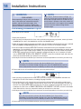
Installation Instructions
Electrolux Front-Load Gas & Electric Dryer
Instrucciones de Instalacion
Secadora eléctrica y a gas de carga frontal Electrolux
Instructions d’installation
Sécheuse à gaz et à l’électricité à chargement frontal Electrolux
137018200 A (0801)
2
Finding Information
Please read and save this guide
Thank you for choosing Electrolux, the new premium brand in home appliances. These Installation
Instructions are part of our commitment to customer satisfaction and product quality throughout the life
of your new appliance.
We view your purchase as the beginning of a relationship. To ensure our ability to continue serving you,
please use this page to record important product information.
Keep a record for quick reference
Purchase date
Electrolux model number
Electrolux serial number
NOTE
Registering your product with Electrolux enhances
our ability to serve you. You can register online at
www.electroluxappliances.com or by dropping
your Product Registration Card in the mail.
Questions?
For toll-free telephone support in the U.S. and Canada: 1-877-4ELECTROLUX (1-877-435-3287)
For online support and product information visit http://www.electroluxappliances.com
Table of contents
Finding information.......................................................... 2
SAFETY........................................................................... 3
• Pre-installation requirements....................................... 3
Installation requirements.............................................. 4-9
• Electrical system requirements.................................... 4
• Gas supply requirements............................................. 5
• Exhaust system requirements.................................. 5-7
• Mobile home installation.............................................. 7
• Clearance requirements.............................................. 8
• Installed dimensions.................................................... 9
Installation.Instructions............................................ 10-18
• Electrical installation.................................................. 10
• Grounding requirements - Electric dryer (USA)......... 10
©2008 Electrolux Major Appliances
• Grounding requirements - Electric dryer (Canada).... 11
• Grounding requirements - Gas dryer......................... 11
• Electrical connection - Electric dryer (3-wire cord).... 12
• Electrical connection - Electric dryer (4-wire cord).... 13
• Gas connection......................................................... 14
• Water connection (Steam Model only).................. 15-16
• General installation.................................................... 17
• Performing installation cycle..................................... 18
Reversing door......................................................... 19-24
Options.......................................................................... 25
• Accessories............................................................... 25
• Replacement parts.................................................... 25
Notes............................................................................. 26
All rights reserved.
Safety
Important Safety Instructions
Recognize safety symbols, words and
labels
Safety items throughout this manual are labeled
with a WARNING or CAUTION based on the risk
type as described below:
This symbol alerts you to situations that may cause serious body
harm, death or property damage.
This symbol alerts you to situations that may cause bodily injury
or property damage.
Read all of the following instructions before
installing and using this appliance:
• Destroy the carton and plastic bags after the dryer
is unpacked. Children might use them for play.
Cartons covered with rugs, bedspreads, or plastic
sheets can become airtight chambers causing suffocation. Place all materials in a garbage container
or make materials inaccessible to children.
or in Canada, CAN/ACG B149.1-2000.
• The dryer is designed under ANSI Z 21.5.1 or
ANSI/UL 2158 - CAN/CSA C22.2 No. 112 (latest
editions) for HOME USE only. This dryer is not
recommended for commercial applications such
as restaurants, beauty salons, etc.
• The instructions in this manual and all other
literature included with this dryer are not meant
to cover every possible condition and situation
that may occur. Good safe practice and caution
MUST be applied when installing, operating and
maintaining any appliance.
WARNING
For your safety the information in this manual
must be followed to minimize the risk of fire
or explosion or to prevent property damage,
personal injury or loss of life. Do not store or use
gasoline or other flammable vapors and liquids in
the vicinity of this or any other appliance.
WHAT TO DO IF YOU SMELL GAS:
• Clothes dryer installation and service must be
performed by a qualified installer, service agency
or the gas supplier.
• Do not try to light any appliance.
• Install the clothes dryer according to the manufacturer’s instructions and local codes.
• Clear the room, building or area of all occupants.
• The electrical service to the dryer must conform
with local codes and ordinances and the latest
edition of the National Electrical Code, ANSI/
NFPA 70, or in Canada, the Canadian electrical
code C22.1 part 1.
• The gas service to the dryer must conform with
local codes and ordinances and the latest edition of the National Fuel Gas Code ANSI Z223.1,
• Do not touch any electrical switch; do not use
any phone in your building.
• Immediately call your gas supplier from a neighbor’s phone. Follow the gas supplier’s instructions.
• If you cannot reach your gas supplier, call the fire
department.
Save these instructions for future
reference.
Pre-installation requirements
Tools and materials needed for installation:
or
or
Phillips, straight, &
Adjustable
Adjustable
square bit screwdrivers
pliers
wrench
4 inch,
i h rigid
i id metal
t l or
semi-rigid metal exhaust duct work
Universal wrench
supplied with
matching washer
Pipe wrench
LP-resistant
for gas
thread tape
supply
(for natural gas
or LP supply)
3-wire or 4-wire
4 in.
240 volt cord kit (10.2 cm)
(electric dryer)
clamp
gas line
shutoff valve
(gas dryer)
Carpenter’s level
½” NPT union flare
adapters (x2) and
flexible gas supply line
(gas dryer)
External
vent hood
Metal foil tape
(not duct tape)
3
4
Installation Requirements
Electrical system requirements
NOTE
Because of potentially inconsistent voltage capabilities, the use of this dryer with power created
by gas powered generators, solar powered generators, wind powered generators or any other
generator other than the local utility company is not recommended.
Electrical requirements for electric dryer:
CIRCUIT - Individual 30 amp. branch circuit
fused with 30 amp. time delay fuses or circuit
breakers. Use separately fused circuits for
washer and dryer. DO NOT operate a washer
and a dryer on the same circuit.
POWER SUPPLY - 3-wire or 4-wire, 240 volt,
single phase, 60 Hz, Alternating Current.
IMPORTANT
This dryer is internally grounded to neutral unless it
was manufactured for sale in Canada. Grounding
through the neutral link is prohibited for: (1) new
branch circuit installations, (2) mobile homes, (3)
recreational vehicles, and (4) areas where local
codes do not permit grounding through the neutral.
3-WIRE POWER SUPPLY CORD KIT (not supplied)
3-wire receptacle
(NEMA type 10-30R)
The dryer MUST employ a 3-conductor power
supply cord NEMA 10-30 type SRDT rated at
240 volt AC minimum, 30 amp, with 3 open
end spade lug connectors with upturned ends
or closed loop connectors and marked for use
Electrical requirements for gas dryer:
CIRCUIT - Individual, properly polarized and
grounded 15 amp. branch circuit fused with 15
amp. time delay fuse or circuit breaker.
POWER SUPPLY - 2-wire, with ground, 120 volt,
single phase, 60 Hz, Alternating Current.
with clothes dryers. For 3-wire cord connection
instructions see ELECTRICAL CONNECTIONS
FOR A 3-WIRE SYSTEM.
4-WIRE POWER SUPPLY CORD KIT (not supplied)
4-wire receptacle
(NEMA type 14-30R)
The dryer MUST employ a 4-conductor power
supply cord NEMA 14-30 type SRDT or ST (as
required) rated at 240 volt AC minimum, 30 amp,
with 4 open end spade lug connectors with
upturned ends or closed loop connectors and
marked for use with clothes dryers. For 4-wire
cord connection instructions see ELECTRICAL
CONNECTIONS FOR A 4-WIRE SYSTEM.
NOTE
Dryers manufactured for sale in Canada have
factory-installed, 4-wire power supply cord
(NEMA 14-30R).
OUTLET RECEPTACLE - NEMA 10-30R or NEMA
14-30R receptacle to be located so the power
supply cord is accessible when the dryer is in the
installed position.
GROUNDING CONNECTION - See “Grounding
requirements” in Electrical Installation section.
Grounding type
wall receptacle
Do not, under
any circumstances,
cut, remove,
or bypass the
grounding prong.
POWER SUPPLY CORD - The dryer is equipped
with a 120 volt 3-wire power cord.
GROUNDING CONNECTION - See “Grounding
requirements” in Electrical Installation section.
Power cord with
3-prong grounded plug
Installation Requirements
Gas supply requirements
WARNING
EXPLOSION HAZARD
Uncoated copper tubing will corrode when
subjected to natural gas, causing gas leaks.
Use ONLY black iron, stainless steel, or plasticcoated brass piping for gas supply.
1. Installation MUST conform with local codes, or
in the absence of local codes, with the National
Fuel Gas Code, ANSI Z223.1 (latest edition). 2. The gas supply line should be 1/2 inch (1.27
cm) pipe.
3. If codes allow, flexible metal tubing may be
used to connect your dryer to the gas supply
line. The tubing MUST be constructed of
stainless steel or plastic-coated brass.
4. The gas supply line MUST have an individual
shutoff valve.
5. A 1/8 inch (0.32 cm) N.P.T. plugged tapping,
accessible for test gauge connection, MUST
be installed immediately upstream of the gas
supply connection to the dryer.
6. The dryer MUST be disconnected from the
gas supply piping system during any pressure
testing of the gas supply piping system at test
pressures in excess of 1/2 psig (3.45 kPa).
7. The dryer MUST be isolated from the gas supply
piping system during any pressure testing of the
gas supply piping system at test pressures equal
to or less than 1/2 psig (3.45 kPa).
8. Connections for the gas supply must comply
with the Standard for Connectors for Gas
Appliances, ANSI Z21.24.
Exhaust system requirements
Use only 4 inch (10.2 cm) diameter (minimum) rigid
or flexible metal duct and approved vent hood
which has a swing-out damper(s) that open when
the dryer is in operation. When the dryer stops,
the dampers automatically close to prevent drafts
and the entrance of insects and rodents. To avoid
restricting the outlet, maintain a minimum of 12
inches (30.5 cm) clearance between the vent hood
and the ground or any other obstruction.
WARNING
Correct
Incorrect
Correct
Incorrect
FIRE HAZARD
Failure to follow these instructions can create
excessive drying times and fire hazards.
The following are specific requirements
for proper and safe operation of your
dryer.
WARNING
FIRE HAZARD
Do not install a clothes dryer with flexible plastic
or metal foil venting materials. Flexible venting
materials are known to collapse, be easily
crushed and trap lint. These conditions will
obstruct clothes dryer airflow and increase the
risk of fire.
If your present system is made up of plastic
duct or metal foil duct, replace it with a rigid or
semi-rigid metal duct. In Canada and the United
States if metal (foil type) duct is installed, it must
be of a specific type identified by the appliance
manufacturer as suitable for use with clothes
dryers and in the United States must also comply
with the Outline for Clothes Dryer Transition Duct,
UL standard 2158A. Also, ensure the present duct
is free of any lint prior to installing dryer duct.
5
6
Installation Requirements
Exhaust system requirements, continued
WARNING
WARNING
FIRE HAZARD
A clothes dryer must be exhausted outdoors. Do not exhaust dryer into a chimney, a wall, a
ceiling, an attic, a crawl space or any concealed
space of a building. A clothes dryer produces
combustible lint. If the dryer is not exhausted
outdoors, some fine lint will be expelled into the
laundry area. An accumulation of lint in any area
of the home can create a health and fire hazard.
WARNING
FIRE HAZARD
• Do not allow combustible materials (for
example: clothing, draperies/curtains, paper)
to come in contact with exhaust system. The
dryer MUST NOT be exhausted into a chimney,
a wall, a ceiling, or any concealed space of a
building which can accumulate lint, resulting in
a fire hazard.
MAXIMUM LENGTH
of 4” (10.2cm) Rigid Metal Duct
VENT HOOD TYPE
(Preferred)
4”
(10.2cm)
2.5”
(6.35cm)
louvered
0
125 ft. (38.10m)
110 ft. (33.53m)
1
115 ft. (35.05m)
100 ft. (30.48m)
2
105 ft. (32.00m)
90 ft. (27.43m)
3
95 ft. (28.96m)
80 ft. (24.38m)
4
85 ft. (25.91m)
70 ft. (21.34m)
Number of 90° turns
• Do not screen the exhaust ends of the vent
system, or use any screws, rivets or other
fasteners that extend into the duct to assemble
the exhaust system. Lint can become caught
in the screen, on the screws or rivets, clogging
the duct work and creating a fire hazard as well
as increasing drying times. Use an approved
vent hood to terminate the duct outdoors, and
seal all joints with duct tape. All male duct pipe
fittings MUST be installed downstream with the
flow of air.
Number of 90° turns
The dryer must be connected to an exhaust
outdoors. Regularly inspect the outdoor exhaust
opening and remove any accumulation of lint
around the outdoor exhaust opening and in the
surrounding area.
FIRE HAZARD
Exceeding the length of duct pipe or number
of elbows allowed in the “MAXIMUM LENGTH”
charts can cause an accumulation of lint in the
exhaust system. Plugging the system could
create a fire hazard, as well as increase drying
times.
MAXIMUM LENGTH
of 4” (10.2cm) Semi-Rigid Metal Duct
VENT HOOD TYPE
(Preferred)
4”
(10.2cm)
louvered
2.5”
(6.35cm)
0
60 ft. (18.29m)
45 ft. (13.72m)
1
50 ft. (15.24m)
35 ft. (10.67m)
2
40 ft. (12.19m)
25 ft. (7.62m)
3
NOT RECOMMENDED
Install male fittings in correct direction:
In installations where the exhaust system is not
described in the charts, the following method
must be used to determine if the exhaust system
is acceptable:
CORRECT
INCORRECT
Installation Requirements
Exhaust system requirements, continued
WARNING
EXPLOSION HAZARD
Do not install the dryer where gasoline or other
flammables are kept or stored. If the dryer is
installed in a garage, it must be a minimum of 18
inches (45.7 cm) above the floor. Failure to do so
can result in death, explosion, fire or burns.
1. Connect an inclined or digital manometer
between the dryer and the point the exhaust
connects to the dryer.
2. Set the dryer timer and temperature to air fluff
(cool down) and start the dryer.
3. Read the measurement on the manometer.
• Compression or crimping of the exhaust system
will cause an increase in vent restriction.
• The exhaust system should be inspected and
cleaned a minimum of every 18 months with
normal usage. The more the dryer is used,
the more often you should check the exhaust
system and vent hood for proper operation.
Exhaust direction
Directional exhausting can be accomplished by
installing a quick-turn 90° dryer vent elbow directly
to exhaust outlet of dryer. Dryer vent elbows are
available through your local parts distributor or
hardware store.
4. The system back pressure MUST NOT be
higher than 1.0 inch of water column. If the
system back pressure is less than 1.0 inch of
water column, the system is acceptable. If the
manometer reading is higher than 1.0 inch of
water column, the system is too restrictive and
the installation is unacceptable.
Although vertical orientation of the exhaust system
is acceptable, certain extenuating circumstances
could affect the performance of the dryer:
• Only the rigid metal duct work should be used.
• Venting vertically through a roof may expose
the exhaust system to down drafts causing an
increase in vent restriction.
• Running the exhaust system through an
uninsulated area may cause condensation and
faster accumulation of lint.
See also CLEARANCE REQUIREMENTS on the
next page.
NOTE
Use of 90° quick-turn elbow required to meet
minimum installation depth.
Manufactured or mobile home installation
1. Installation MUST conform to current
Manufactured Home Construction & Safety
Standard, Title 24 CFR, Part 32-80 (formerly the
Federal Standard for Mobile Home Construction
and Safety, Title 24, HUD Part 280) or Standard
CAN/CSAZ240 MH.
2. Dryer MUST be exhausted outside (outdoors, not
beneath the mobile home) using metal ducting
that will not support combustion. Metal ducting
must be 4 inches (10.16 cm) in diameter with no
obstructions. Rigid metal duct is preferred.
3. If dryer is exhausted through the floor and
area beneath the mobile home is enclosed,
the exhaust system MUST terminate outside
the enclosure with the termination securely
fastened to the mobile home structure.
4. Refer to previous sections in this guide for other
important exhaust venting system requirements.
5. When installing a gas dryer into a mobile home,
a provision must be made for outside make up
air. This provision is to be not less than twice
the area of the dryer exhaust outlet.
6. Installer MUST anchor this (1) dryer or (2) dryer
mounted on pedestal to the floor with approved
Mobile Home Installation Kit - P/N 137067200.
7
8
Installation Requirements
Clearance requirements
IMPORTANT
MINIMUM INSTALLATION CLEARANCES - Inches (cm)
DO NOT INSTALL YOUR DRYER:
1. In an area exposed to dripping water or outside
weather conditions.
2. In an area where it will come in contact with
curtains, drapes, or anything that will obstruct
the flow of combustion and ventilation air.
3. On carpet. Floor MUST be solid with a maximum
slope of 1 inch (2.54 cm).
INSTALLATION IN A RECESS OR CLOSET
1. A dryer installed in a bedroom, bathroom,
recess or closet, MUST be exhausted outdoors.
SIDES
Alcove
REAR
TOP
FRONT
0” (0 cm) 0” (0 cm)* 0” (0 cm)
n/a
Under0” (0 cm) 0” (0 cm)* 0” (0 cm)
Counter
n/a
Closet
0” (0 cm) 0” (0 cm)* 0” (0 cm) 1” (2.54 cm)
* For other than straight back venting, a quick-turn 90°
dryer vent elbow must be installed to achieve 0” (0 cm)
installation.
0”
(0cm)
2. No other fuel burning appliance shall be
installed in the same closet as the gas dryer.
0”
(0cm)
3. Your dryer needs the space around it for proper
ventilation.
DO NOT install your dryer in a closet with a solid
door.
4. Closet door ventilation required: A minimum
of 120 square inches (774.2 cm²) of opening,
equally divided at the top and bottom of the
door, is required. Openings should be located
3 inches (7.6 cm) from bottom and top of door.
Openings are required to be unobstructed
when a door is installed. A louvered door with
equivalent air openings for the full length of the
door is acceptable.
1”
(2.54cm)
0”
(0cm)
3”
(7.6cm)
60 sq. in.
(387.1cm²)
NOTE
60 sq. in.
(387.1cm²)
3”
(7.6cm)
closet door
To achieve an installation with 0” (0 cm) clearance
for the back of the dryer (for other than straight
back venting), a quick-turn 90° dryer vent elbow
must be installed as described previously in this
manual.
Installation Requirements
Installed dryer dimensions
50.6” (128.5cm)*
to clear open door
27.00”
(68.5cm)
31.50” (80cm)*
to front of closed door
38.00”
(96.5cm)
electrical
supply on
rear of unit
53.00”
(134.5cm)
freestand dryer
on floor
centerline
height for
rear vent
gas supply
pipe on rear
of gas unit
3.40”
(8.5cm)
floor line
1.4”
(3.5cm)
dryer mounted on
optional pedestal
18.25”
(46.5cm)
16.25”
(41.5cm)
floor line
* To obtain these minimal depth dimensions, dryer must either be vented straight back or
3.75”
with a quick-turn 90° elbow. Connection of water inlet hose on Steam Models adds 3/4 in.
(9.5cm)
(2 cm) to installation depth. Upward venting of exhaust on pedestal-mounted or freestanding
dryer adds approximately 4 in. (10.2 cm) to installation depth. Downward venting of exhaust
on pedestal-mounted dryer adds approximately 1.7 in. (4.3 cm) to installation depth.
50.6” (128.5cm)*
to clear open door
13.50”
(34.5cm)
to center of rear vent
27.00”
(68.5cm)
31.50” (80cm)*
to front of closed door
75.75”
(192.5cm)
electrical
supply on
rear of unit
gas supply
pipe on rear
of gas unit
centerline
height for
rear vent
41.00”
(104cm)
39.00”
(99cm)
* To obtain these minimal depth dimensions, dryer must either be vented straight back or with a quick-turn 90° elbow.
Connection of water inlet hose on Steam Models adds 3/4 in. (2 cm) to installation depth. Upward or downward venting
of exhaust on stacked dryer adds approximately 4 in. (10.2 cm) to installation depth.
9
10
Installation Instructions
Electrical installation
The following are specific requirements for proper
and safe electrical installation of your dryer. Failure
to follow these instructions can create electrical
shock and/or a fire hazard.
WARNING
ELECTRICAL SHOCK HAZARD
• This appliance MUST be properly grounded.
Electrical shock can result if the dryer is not
properly grounded. Follow the instructions in
this manual for proper grounding.
• Do not use an extension cord with this dryer.
Some extension cords are not designed to
withstand the amounts of electrical current this
dryer utilizes and can melt, creating electrical
shock and/or fire hazard. Locate the dryer
within reach of the receptacle for the length
power cord to be purchased, allowing some
slack in the cord. Refer to the pre-installation
requirements in this manual for the proper
power cord to be purchased.
WARNING
ELECTRICAL SHOCK HAZARD
• A U.L.-approved strain relief must be installed
onto power cord. If the strain relief is not
attached, the cord can be pulled out of the
dryer and can be cut by any movement of the
cord, resulting in electrical shock.
• Do not use an aluminum wired receptacle with
a copper wired power cord and plug (or vice
versa). A chemical reaction occurs between
copper and aluminum and can cause electrical
shorts. The proper wiring and receptacle is a
copper wired power cord with a copper wired
receptacle.
NOTE
Dryers operating on 208 volt power supply will
have longer drying times than dryers operating
on 240 volt power supply.
Grounding requirements - Electric dryer (USA)
WARNING
ELECTRICAL SHOCK HAZARD
Improper connection of the equipment grounding
conductor can result in a risk of electrical shock.
Check with a licensed electrician if you are in
doubt as to whether the appliance is properly
grounded.
For a grounded, cord-connected dryer:
1. The dryer MUST be grounded. In the event of
a malfunction or breakdown, grounding will
reduce the risk of electrical shock by a path of
least resistance for electrical current.
2. After you purchase and install a 3 wire or 4
wire power supply cord having an equipmentgrounding conductor and a grounding plug
that matches you wiring system, the plug
MUST be plugged into an appropriate, copper
wired receptacle that is properly installed and
grounded in accordance with all local codes and
ordinances. If in doubt, call a licensed electrician.
DO NOT modify the plug you’ve installed on this
appliance.
For a permanently connected dryer:
1. The dryer MUST be connected to a grounded
metal, permanent wiring system; or an
equipment grounding conductor must be run
with the circuit conductors and connected to
the equipment-grounding terminal or lead on
the appliance.
Installation Instructions
Grounding requirements - Electric dryer (Canada)
WARNING
ELECTRICAL SHOCK HAZARD
Improper connection of the equipment grounding
conductor can result in a risk of electrical shock.
Check with a licensed electrician if you are in
doubt as to whether the appliance is properly
grounded.
For a grounded, cord-connected dryer:
1. The dryer MUST be grounded. In the event of
a malfunction or breakdown, grounding will
reduce the risk of electrical shock by a path of
least resistance for electrical current.
2. Since your dryer is equipped with a power
supply cord having an equipment-grounding
conductor and a grounding plug, the plug must
be plugged into an appropriate outlet that is
properly installed and grounded in accordance
with all local codes and ordinances. If in doubt,
call a licensed electrician.
DO NOT modify the plug provided with the
appliance.
Grounding requirements - Gas dryer (USA and Canada)
Grounding type
wall receptacle
Do not, under
any circumstances,
cut, remove,
or bypass the
grounding prong.
Power cord with
3-prong grounded plug
1. The dryer is equipped with a three-prong
(grounding) plug for your protection against
shock hazard and should be plugged
directly into a properly grounded three-prong
receptacle.
DO NOT cut or remove ground prong from the
plug.
11
12
Installation Instructions
Electrical connection (non-Canada) - 3 wire cord
3-wire receptacle
(NEMA type 10-30R)
WARNING
30 AMP
NEMA 10-30
ELECTRICAL SHOCK HAZARD
Neutral
(center wire)
Failure to disconnect power source before servicing
could result in personal injury or even death.
1. Turn off power supply to outlet.
Access cover
screw
2. Remove the screw securing the terminal block
access cover in the lower corner on the back of
the dryer.
Terminal
block
Line 2
(BRASS terminal)
3. Install a UL-approved strain relief according
to the power cord/strain relief manufacturer’s
instructions in the power cord entry hole below
the access panel. At this time, the strain relief
should be loosely in place.
Neutral
(SILVER terminal)
Line 1
(BRASS terminal)
4. Thread an UNPLUGGED, UL-approved, 30 amp.
power cord, NEMA 10-30 type SRDT, through the
strain relief.
Internal ground
(GREEN screw)
Install
UL-approved
strain relief here
5. Attach the power cord neutral (center wire)
conductor to the SILVER colored center
terminal on the terminal block. Tighten the
screw securely.
6. Attach the remaining two power cord outer
conductors to the outer, BRASS colored
terminals on the terminal block. Tighten both
screws securely.
WARNING
ELECTRICAL SHOCK HAZARD
Do not make a sharp bend or crimp wiring/ conductor at connections.
7. Follow manufacturer’s guidelines for firmly
securing the strain relief and power cord.
8. Reinstall the terminal block cover.
IMPORTANT
If moving dryer from a 4-wire system and
installing it in a 3-wire system, move the internal
ground from the center terminal back to the
GREEN screw next to the terminal block.
Terminal screw
recovery slot
NOTE
If a terminal screw falls during cord installation,
it can be retrieved in the terminal screw recovery
slot below the access panel.
DO NOT remove
internal ground in
a 3-wire system!!
Neutral
terminal
Installation Instructions
Electrical connection (non-Canada) - 4 wire cord
4-wire receptacle
(NEMA type 14-30R)
WARNING
Neutral
(WHITE wire)
Ground
(GREEN wire)
30 AMP
NEMA 14-30
ELECTRICAL SHOCK HAZARD
Failure to disconnect power source before servicing
could result in personal injury or even death.
1. Turn off power supply to outlet.
2. Remove the screw securing the terminal block
access cover in the lower corner on the back of
the dryer.
3. Install a UL-approved strain relief according
to the power cord/strain relief manufacturer’s
instructions in the power cord entry hole below
the access panel. At this time, the strain relief
should be loosely in place.
4. Thread an UNPLUGGED, UL-approved, 30
amp. power cord, NEMA 14-30 type ST or
SRDT, through the strain relief.
5. Disconnect the internal (BLACK) dryer harness
ground wire from the (GREEN) ground screw
next to the terminal block.
6. Attach the ground (GREEN) power cord wire
to the cabinet with the ground (GREEN) screw.
Tighten the screw securely.
7. Move the internal dryer harness ground
(BLACK) wire to the terminal block and attach
it along with the neutral (WHITE) power cord
wire conductor to the center, SILVER colored
terminal on the terminal block. Tighten the
screw securely.
8. Attach the RED and BLACK power cord
conductors to the outer, BRASS colored
terminals on the terminal block. Tighten both
screws securely.
Access cover
screw
Terminal
block
Line 2
(BRASS terminal)
Neutral
(SILVER terminal)
Line 1
(BRASS terminal)
Internal ground
(GREEN screw)
Install
UL-approved
strain relief here
Terminal screw
recovery slot
NOTE
If a terminal screw falls during cord installation,
it can be retrieved in the terminal screw recovery
slot below the access panel.
Move internal ground (BLACK)
wire to neutral (SILVER)
terminal for 4-wire system.
WHITE
neutral wire
WARNING
ELECTRICAL SHOCK HAZARD
Do not make a sharp bend or crimp wiring/ conductor at connections.
9. Follow manufacturer’s guidelines for firmly
securing the strain relief and power cord.
10. Reinstall the terminal block cover.
Neutral
terminal
GREEN
ground screw
GREEN
ground wire
BLACK or
RED power wire
BLACK
or RED
power wire
13
14
Installation Instructions
Gas connection
1. Remove the shipping cap from gas pipe at the
rear of the dryer.
IMPORTANT
DO NOT connect the dryer to L.P. gas service
without converting the gas valve. An L.P.
conversion kit must be installed by a qualified
gas technician.
2. Connect a 1/2 inch (1.27 cm) I.D. semi-rigid or
approved pipe from gas supply line to the 3/8
inch (0.96 cm) pipe located on the back of the
dryer. Use a 1/2 inch to 3/8 inch (1.27 cm to
0.96 cm) reducer for the connection. Apply an
approved thread sealer that is resistant to the
corrosive action of liquefied gases on all pipe
connections.
Manual
Shutoff Flare
Valve Union
GAS FLOW
Flare
Union
3. Open the shutoff valve in the gas supply line to
allow gas to flow through the pipe. Wait a few
minutes for gas to move through the gas line.
to
dry
e
r
fro
m
ga
ss
up
ply
Shutoff Valve Open position
4. Check for gas system leaks with a manometer.
If a manometer is not available, test all
connections by brushing on a soapy water
solution.
WARNING
Closed
Open
N ipple
Flexible
Connector
Inlet Pipe on
Back of Dryer
All connections must be wrench-tightened
IMPORTANT
The supply line must be equipped with an
approved manual shutoff valve. This valve
should be located in the same room as the dryer
and should be in a location that allows ease of
opening and closing. Do not block access to the
gas shutoff valve.
EXPLOSION HAZARD
NEVER test for gas leaks with an open flame.
Installation Instructions
Water connection (Steam Model only)
1. Turn off COLD water supply to washer,
2. Remove COLD inlet hose from COLD water
supply and inspect for rubber washer. Replace
washer if it is torn or worn out.
RUBBER WASHER
MUST BE PRESENT
AND UNDAMAGED
COLD INLET HOSE
TO WASHER
3. Momentarily turn on COLD supply and run
some water into a bucket or container to clear
any contaminants in the line.
4. Remove hose kit from dryer drum and inspect
hose couplings for proper placement of rubber
washers.
RUBBER WASHERS
MUST BE PRESENT
15
16
Installation Instructions
Water connection, con’t (Steam Model only)
1. If your installation has room for the COLD
water supply to accept the “Y” connector
directly, thread the “Y” connector to the COLD
water supply and snug it by hand; then tighten
it another 2/3 turn with pliers.
DIRECT CONNECTION
OR WITH EXTENSION
WATER INLET ON DRYER
NOTE
If you were able to install the “Y” connector directly
to the COLD water supply, please skip to step 8.
2. If there is not room to install the “Y” connector
directly, thread the short extension hose on to
the COLD water supply and snug it by hand;
then tighten it another 2/3 turn with pliers.
3. Thread the “Y” connector to the short
extension hose and snug it by hand; then
tighten it another 2/3 turn with pliers.
4. Connect the COLD inlet hose for the washer
to the “Y” connector and snug it by hand; then
tighten it another 2/3 turn with pliers.
5. Connect the straight end of the long hose from
the kit to the other outlet on the “Y” connector
and snug it by hand. Connect the hose’s 90°
coupling to the brass water inlet on the back
of the dryer and snug it by hand. Tighten each
connection of the dryer inlet hose another 2/3
turn with pliers.
6. Turn on the water and check for leaks at all
connections.
COLD WATER SUPPLY
HOSE TO WASHER
Installation Instructions
General installation
1. Connect the exhaust duct to the outside
exhaust system (see pages 5 through 7). Use
of a 4” (10.2 cm) clamp is recommended to
connect the dryer to the exhaust vent system.
Use metal foil tape to seal all other joints.
2. Carefully slide the dryer to its final position.
Adjust one or more of the legs until the dryer is
resting solidly on all four legs. Place a level on
top of the dryer. The dryer MUST be level and
resting solidly on all four legs. Rock alternating
corners to check for stability. Remove and
discard door tape.
IMPORTANT
Be sure the power is off at a circuit breaker/fuse
box before plugging the power cord into an outlet.
3. Plug the power cord into a grounded outlet.
4. Turn on the power at the circuit breaker/fuse
box.
5. Read the Use & Care Guide provided with
the dryer. It contains valuable and helpful
information that will save you time and money.
6. See the next page about performing a brief,
helpful “Installation Cycle” for your new dryer.
7. If you have any questions during initial
operation, please review the “Avoid Service
Checklist” in your Use & Care Guide before
calling for service.
8. Place these instructions in a location near the
dryer for future reference.
NOTE
A wiring diagram and technical data sheet are
located inside the dryer console.
Grounding type
wall receptacle
Do not, under
any circumstances,
cut, remove,
or bypass the
grounding prong.
Power cord with
3-prong grounded plug
17
18
Installation Instructions
WARNING
FIRE HAZARD
Before operating the dryer, make sure the dryer
area is clear and free of combustible materials,
gasoline, and other flammable vapors. Also
see that nothing (such as boxes, clothing, etc.)
obstructs the flow of combustion and ventilation air.
NOTE
On gas dryers, before the burner will light, it is
necessary for the gas line to be bled of air. If the
burner does not light within 45 seconds the first
time the dryer is turned on, the safety switch will
shut the burner off. If this happens, press cancel
and wait 5 minutes before making another
attempt to light.
Performing Installation Cycle
If your dryer has this console:
1.Empty the dryer drum.
2.After you plug in the dryer the first time: wake up the dryer by pressing any button, rotate cycle knob
to touch up cycle, press the start button and then the cancel button.
3.Wake up the dryer again by pressing any button, then immediately and simultaneously press and hold
both the sanitize and my favorite buttons for 5 seconds, or until the LCD display changes.
4.The LCD window will display INSTAL CYCLE and show estimated time of cycle completion. Press the
start button. The Installation Cycle will automatically test for correct cord connection (on electric models) and presence of gas supply (on gas models). At cycle completion, the LCD window may display
INSTAL PASS!, meaning your new dryer is properly installed and ready for use. If it prompts an action
such as SERVICE CORD, NO GAS or call service 877 435 3287, review the installation steps and make the
necessary corrections before you attempt to use the dryer.
5.Your dryer will exit the Installation Cycle and return to normal operation the next time you wake it up.
NOTE
Dryer will stay awake for 3 minutes after the Installation Cycle. If you wish to
immediately run the dryer through a drying cycle, press the cancel button to put the
unit to sleep and then rewake it immediately to continue the normal operating mode.
6.Please read the Use & Care Guide and enjoy your new premium dryer!
If your dryer has this console:
1.After you plug in the dryer the first time: wake up the dryer by pressing any button and follow the
prompts on the LCD User Interface, including language selection.
2.The Installation Cycle will automatically test for correct cord connection (on electric models), presence of gas supply (on gas models) and free flow of exhaust vent. At cycle completion, the LCD user
interface may display INSTAL PASS!, meaning your new dryer is properly installed and ready for use. If
it prompts an action such as SERVICE CORD, NO GAS or call service 877 435 3287, review the installation
steps and make the necessary corrections before you attempt to use the dryer.
3.Your dryer will exit the Installation Cycle and return to normal operation the next time you wake it up.
NOTE
Dryer will stay awake for 3 minutes after the Installation Cycle. If you wish to
immediately run the dryer through a drying cycle, press the cancel button to put the
unit to sleep and then rewake it immediately to continue the normal operating mode.
4.Please read the Use & Care Guide and enjoy your new premium dryer!
Reversing Door
Preparing to reverse door swing
1 Be sure you have adequate swing area before reversing door.
Tools needed:
2 You will need a screw driver with a #2 square bit.
3 Protect flat work surface, such as top of dryer or floor near dryer,
with a soft cloth or towel.
4 Be sure dryer is unplugged from power source!
Screwdrivers with
#2 square &
straight bit
WARNING
ELECTRICAL SHOCK HAZARD
Failure to disconnect power source before servicing
could result in personal injury or even death. Removing door and hardware
A) Removing Trim Ring
B) Removing Door from Front Panel
1 Open door to 90 degree angle.
2 Remove and save trim plug and long,
course-thread, panhead screw.
1 Reopen door to 90 degree angle.
3 Close door.
3 While supporting door with the other hand,
remove 3 short, fine-thread, counter-sunk
screws.
4 Rotate door trim approximately ¾” counterclockwise and pull ring away from door.
2 Remove 2 short, course-thread, panhead
screws.
4 Gently place door face down on flat, covered
work surface.
19
20
Reversing Door
Reversing door
C) Reversing Hardware on Front Panel
D) Removing Door Hardware
1 Remove 2 short, course-thread, panhead
screws from striker and 2 plastic hole plugs.
1 Remove 2 long, course-thread, counter-sunk
screws and latch plate. Set latch aside.
2 Rotate striker and move to opposite
opening. Attach with 2 short, course-thread,
panhead screws.
2 Remove 4 long, course-thread, recessed
screws and hinge. Set hinge aside.
3 Install original plastic hole plugs or use new
plugs supplied with dryer.
Reversing Door
E) Removing Latch Indicator
F) Removing Hole Plug
1 Insert flat blade screwdriver into open slot of
latch indicator.
1 Insert flat blade screwdriver into open slot of
hole plug.
2 Gently pry upward to release tab.
2 Gently pry upward to release tab.
3 Pull the hole plug out and set it aside.
3 Pull the indicator out and set it aside.
21
22
Reversing Door
G) Reinserting Latch Indicator
H) Reinserting Hole Plug
1 Rotate the latch indicator and move it to the
opposite hole in the door.
1 Rotate the hole plug and move it to the
opposite hole in the door.
insert indicator
through slot
2 Firmly insert the two small tabs on either
side of the hole plug into the two slots on
either side of the hole in the door.
insert tab
2 Firmly insert the two small tabs on either
side of the latch indicator into the two slots
on either side of the hole in the door.
insert tab
3 Firmly press downward on the hole plug until
the tab snaps in place.
insert tab
insert tab
3 Firmly press downward on the indicator until
the tab snaps in place.
press down
and snap
press down
and snap
Reversing Door
I) Reattaching Latch Plate
K) Reattaching Door to Front Panel
1 Rotate latch plate and move to opposite side
of door above indicator.
1 Use side locating pins to align hinge and
install 1 short, fine-thread, counter-sunk
screw in center hole of hinge side.
2 Reattach with 2 long, course-thread,
counter-sunk screws.
J) Reattaching Hinge
2 Install other 2 short, fine-thread, countersunk screws in upper and lower holes of
hinge side.
1 Rotate hinge and move to opposite side of
door above hole plug.
3 Install 2 short, course-thread, panhead
screws through face of hinge plate.
2 Reattach with 4 long, course-thread,
counter-sunk screws.
4 Close door and test operation of latch.
23
24
Reversing Door
L) Reversing Trim Ring
M) Reinstalling Trim Ring
1 Trim ring orientation is marked on the back.
1 Close door.
2 Remove trim ring cover plate. To remove
plate from left, pivot point is down. To
remove plate from right, pivot point is up.
2 Orient trim so 12 position is approximately
¾” to the left of top center. Opening in ring
should be on the hinge side.
UP
3 Insert trim ring in slots and rotate clockwise
approximately ¾”.
3 Rotate and move trim ring cover plate to
opposite opening in trim and reinsert.
N) Reinstalling Trim Plug
1 Open door to 90 degree angle.
2 Install trim plug with 1 long, course-thread,
panhead screw.
O) Plug in dryer and continue operation.
Options
Accesories
MATCHING STORAGE PEDESTAL
Island White Pedestal - P/N EPWD15IW
Mediterranean Blue - P/N EPWD15MB
Silver Sands Pedestal - P/N EPWD15SS
Turquoise Sky Pedestal - P/N EPWD15TS
A storage pedestal accessory, specifically
designed for this dryer may be used to elevate the
dryer for ease of use. This pedestal will add about
15” (38.1cm) to the height of your unit for a total
height of 53” (134.62 cm).
CAUTION
Failure to use accessories manufactured by (or
approved by) the manufacturer could result in
personal injury, property damage or damage to
the dryer.
27.00”
(68.58c
m
)
DRYER STACKING KIT
P/N 134700400
A kit for stacking this dryer on top of matching
washer came with the initial purchase of this dryer.
If you desire another stacking kit, you may order
one.
15.00
(38.1 ”
0cm)
LP CONVERSION KIT
P/N 134709300
Gas dryers intended for use in a location supplied
with LP must use a conversion kit prior to
installation.
26.44”
cm)
(67.16
MOBILE HOME INSTALLATION KIT
P/N 137067200
Installations in mobile homes require use of
MOBILE HOME INSTALLATION KIT.
DRYING RACK
P/N 134912700
An expandable drying rack came with the initial
purchase of this dryer. If you desire another drying
rack, you may order one.
UNIVERSAL APPLIANCE WRENCH
P/N 137019200
The matching washer to this dryer was supplied
with a UNIVERSAL APPLIANCE WRENCH. If you
desire another wrench, you may order one.
Replacement parts: 1-877-4ELECTROLUX (1-877-435-3287)
If replacements parts are needed for your dryer,
contact the source where you purchased your
dryer, call 1-877-4ELECTROLUX (1-877-435-3287),
or visit our website, www.electroluxappliances.
com, for the Electrolux Authorized Parts Distributor
nearest you.
WARNING
ELECTRICAL HAZARD
Label all wires prior to disconnection when
servicing controls. Wiring errors can cause
improper and dangerous operation. Verify proper
operation after servicing.
25
26
Notes