1
OPERATION AND PARTS MANUAL
STRUCTURAL
CONCRETE PUMP
© COPYRIGHT 2004, MULTIQUIP INC.
MODEL ST-45HRM CE
(HATZ ENGINE)
Revision #0 (02/23/04)
MULTIQUIP (UK)
HANOVER MILL
FITZROY STREET
ASHTON-UNDER-LYNE
LANCASHIRE, OL7 OTL
UNITED KINGDOM
PH. 0161-339-2223
FAX. 0161-339-3226
Proposition 65 Warning
Thank you for your purchase of the Mayco/Multiquip ST45
concrete pump. It has been engineered and designed for
maximum performance and safety. For long service life and
improved reliability, please follow all safety, operating and
maintenance instructions referenced in this manual.
This concrete pump is to be soley used for the pumping of concrete
and is not intended for any other purpose. The pumping of
flammable or combustable materials is strictly prohibited. NEVER
operate this pump in an explosive environment.
All warranties are voided if the pump is not used for its intended
purpose.
HERE'S HOW TO GET HELP
PLEASE HAVE THE MODEL AND SERIAL NUMBER
ON-HAND WHEN CALLING
PARTS/SERVICE/ WARRANTY
LANCASHIRE, OL7 OLT
UNITED KINGDOM (UK) CALL:
PHONE: 161-339-2223
FAX: 161-339-3226
PAGE 2 — MAYCO ST-45HRM CE PUMP — OPERATION & PARTS MANUAL — REV. #0 (02/23/04)
TABLE OF CONTENTS
MAYCO ST-45HRM CE
CONCRETE PUMP
Here’s how To Get Help.............................................2
Table of Contents ......................................................3
Pump Specifications ..................................................4
Engine Specifications ................................................5
Dimensions .............................................................. 6
Noise Measurement ..................................................7
Safety Message Alert Symbols ............................ 8-9
Rules for Safe Operation .................................. 10-12
Operation and Safety Decals ............................ 13-15
Important Hand Signals ..........................................16
General Information .......................................... 17-18
How it Works............................................................19
Pump Components ........................................... 20-21
Control Box Components ........................................22
Engine Components ...............................................23
Operating Procedures....................................... 24-28
Inspection .......................................................... 29-31
Initial Start-Up Procedure ................................. 32-35
Trailer Safety Guidelines ................................... 36-37
Towing Information ............................................ 38-41
Braking System ................................................. 42-47
Troubleshooting (Brake System).............................48
Torque Tables ..........................................................49
Maintenance (Pump) ........................................ 50-58
Hydraulic Hose Connections ............................. 59-61
Manifold Port Locations ..........................................62
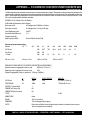
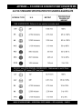
Appendix — Concrete Mix Information ............. 64-65
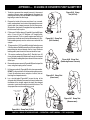
Appendix — Slump Test Procedure ........................66
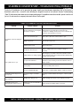
Troubleshooting (Engine) ........................................67
Troubleshooting (Hydraulic System) .......................68
Troubleshooting (Electrical System) .......................69
Appendix — Recommended
Shotcrete System ..........................70-71
Appendix — Recommended
Shotcrete Accessories ...................72-73
Explanation Of Code In Remarks Column ..............74
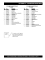
Suggested Spare Parts ...........................................75
PARTS ILLUSTRATIONS
Decal Placement ................................................76-77
Safet Grids Assembly.........................................78-79
Hub and Drum Assembly ...................................80-81
Brake Components Assembly ............................82-83
Towing Coupler Assembly ..................................84-85
Hopper Assembly ...............................................86-87
Hopper Attachment Assembly ...........................88-89
Hopper Interior Assembly ..................................90-91
Shuttle Cylinder Assembly .................................92-93
Fuel and Hydraulic Tank Assembly ....................94-97
Front Cover Assembly........................................98-99
Heat Exchanger Assembly .............................100-101
Engine and Frame Assembly .........................102-103
Throttle and Water Filter Assembly ................104-105
Hydraulic Pump Assembly .............................106-107
Lubrication Pistons Assembly ........................108-109
Electrical System Assembly ...........................110-111
Accumulator Assembly...................................112-113
Manifold Assembly .........................................114-115
Remixer Control Assembly ............................116-117
Battery Assembly ...........................................118-119
Lubrication Panel ...........................................120-121
Control Box Interior Door Assembly ..............122-123
Control Box Mounting Assembly ...................124-125
Control Box Assembly ...................................126-127
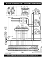
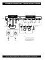
Control Box Door Wiring Diagram ......................... 128
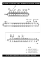
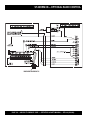
Control Box Interior Wiring Diagram ..................... 129
Terminal Block Wiring Diagram ............................. 130
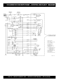
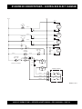
Control Box Electrical Diagram ......................132-134
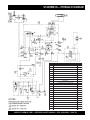
Hydraulic Diagram ............................................... 135
Optional Radio Control.......................................... 136
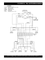
Wiring Diagram (Tail Lights) ................................. 137
Terms and Conditions Of Sale — Parts ................ 138
Mayco Pump Warranty .......................................... 139
NOTE
Specification and part
number are subject to
change without notice.
MAYCO ST-45HRM CE PUMP — OPERATION & PARTS MANUAL — REV. #0 (02/23/04) — PAGE 3
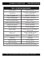
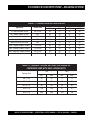
ST-45HRM CE CONCRETE PUMP — PUMP SPECIFICATIONS
Table 1. ST-45 Pump Specifications
Pumping Method
Reciprocating Piston
Pumping Rate
Up to 34.4 cu. meters per hour*
(45 cu. yds. per hour*)
Maximum Aggregate Size
38mm (1-1/2 in. minus)
Ver tical Pumping Height
Up to Excess of 76m (250 ft.)
Horizontal Pumping Distance
305m* (1000 ft.)
Cylinder Lubrication Box Capacity
26.5 Liters (7 Gallons)
Hydraulic Fluid Capacity
219 Liters (58 Gallons)
Fuel Tank Capacity
76 Liters (20 Gallons)
Hopper Capacity
283 liters (10 cu. ft. ) with optional
fwd/rev remixer
Material Hose
76.2 mm, 101.6 mm, 127 mm
(3 in., 4 in., 5 in. dia.)
Remote Control (25 ft. cable)
optional
Dimensions
See Page 6
Weight (with fluids)
1,907 kg (4,206 lbs.)
Weight (dry/shipping)
1,832 kg (4,040 lbs.)
* Volume output will vary depending on mix design, slump, line size used and job site condititons
PAGE 4 — MAYCO ST-45HRM CE PUMP — OPERATION & PARTS MANUAL — REV. #0 (02/23/04)
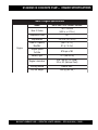
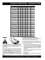
ST-45HRM CE CONCRETE PUMP— ENGINE SPECIFICATIONS
Table 2. Engine Specifications
E n g in e
Model
HATZ 3M41 57HP DIESEL ENGINE
Bore X Stroke
102 x 105 mm
(4.02 in. x 4.13 in.)
Compression Ratio
18.7
Displacement
2,573 cc (157 cu. in)
Lube Oil Capacity
Max/Min
(8.6 L / 5.1 L)
9.1 qt. / 5.4 qt.
Engine Speed
Full Idle
875 r pm ±100
Battery Type
12 V (88/143 Ah)
Engine Lubrication
SAE 10W-30 (Oil Grade)
SG or SF (Service Class)
Star ting Method
Electric Star t
Dry Net Weight
255 kg (562 lbs.)
MAYCO ST-45HRM CE PUMP — OPERATION & PARTS MANUAL — REV. #0 (02/23/04) — PAGE 5
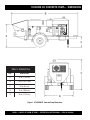
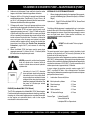
ST-45HRM CE CONCRETE PUMP— DIMENSIONS
TABLE 3. DIMENSIONS
REF.
DIMENSIONS
A
45 in. (114.3 cm.)
B
162 in. (411.5 cm.)
C
24 in. (61 cm.)
D
73 in. (185.4 cm.)
E
68 in. (172.2 cm.)
Figure 1. ST-45HRM CE Concrete Pump Dimensions
PAGE 6 — MAYCO ST-45HRM CE PUMP — OPERATION & PARTS MANUAL — REV. #0 (02/23/04)
ST-45HRM CE CONCRETE PUMP— NOISE MEASUREMENT
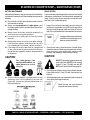
EC Declaration of Conformity
In accordance with EN 45014:1998
We
of
Multiquip (UK) Ltd
Hanover Mil, Fitzroy Street Ashton Under Lyne OL7 0TL
declare that:
Equipment
Concrete conveying and spraying apparatus
Model name/number
(S/N’s 220704 and 220705)
Is in accordance with the following directives:
98/37/EC
89/336/EEC
2000/14/EC
The Machinery Directive
Electromagnetic Compatibility Directive
The noise Emission in the Environment by Equipment for Use
Outdoors Directive
has been designed and manufactured to the following specifications:
pr EN 12001:1995
Conveying, spraying and and distributing machines for concrete and mortar –
safety requirements.
BS EN 292-2:1991
Safety of machinery. Basic concepts
BS EN 982:1966
Safety of machinery. Safety requirements for fluid power systems and their
components. Hydraulics
BS EN 61000-6-4:2001
Electromagnetic compatibility (EMC). Generic standards. Emission standard
for industrial environments.
Noise measurements have been made in accordance with BS EN ISO 3744:1995 with internal control of production (Schedule 8/Annex V). The
declared noise values are as follows:
Measured Sound Power Level
103 db (LwA)
Guaranteed Sound Power Level
106 db (LwA)
I hereby declare that the equipment named above has been designed to comply with the relevant sections of the above referenced specifications.
The unit complies with all essential requirements of the Directives.
Signed by: ................................................................................................................
Name:
L. Whitelegg
Position
Done at
Ashton-Under-Lyne
On
MAYCO ST-45HRM CE PUMP — OPERATION & PARTS MANUAL — REV. #0 (02/23/04) — PAGE 7
ST-45HRM CE CONCRETE PUMP— SAFETY MESSAGE ALERT SYMBOLS
FOR YOUR SAFETY AND THE SAFETY OF OTHERS!
Safety precautions should be followed at all times when operating
this equipment. Failure to read and understand the Safety
Messages and Operating Instructions could result in injury to
yourself and others.
NOTE
This Owner's Manual has been
developed to provide complete
instructions for the safe and efficient
operation of the Multiquip Mayco
ST-45HRM CE Structural Concrete
pump. Refer to the engine
manufacturers instructions for data
relative to its safe operation.
Before using this concrete pump , ensure that the operating
individual has read and understands all instructions in this
manual.
SAFETY MESSAGE ALERT SYMBOLS
The three (3) Safety Messages shown below will inform you
about potential hazards that could injure you or others. The
Safety Messages specifically address the level of exposure to
the operator, and are preceded by one of three words: DANGER,
DANGER:
You WILL be KILLED or
SERIOUSLY injured if you do not follow
directions.
WARNING: You CAN be KILLED or
SERIOUSLY injured if you do not follow
directions.
CAUTION:
You CAN be injured if you
do not follow directions
HAZARD SYMBOLS
Lethal Exhaust Gases
Diesel engine exhaust gases contain poisonous
carbon monoxide. This gas is colorless and
odorless, and can cause death if inhaled.
NEVER operate this equipment in a confined
area or enclosed structure that does not
provide ample free flow air.
Explosive Fuel
Diesel fuel is extremely flammable, and its
vapors can cause an explosion if ignited. DO
NOT start the engine near spilled fuel or
combustible fluids. DO NOT fill the fuel tank
while the engine is running or hot. DO NOT
overfill tank, since spilled fuel could ignite if it
comes into contact with hot engine parts or
sparks from the ignition system. Store fuel in
approved containers, in well-ventilated areas
and away from sparks and flames. NEVER
use fuel as a cleaning agent.
Burn Hazards
Engine components can generate extreme heat.
To prevent burns, DO NOT touch these areas
while the engine is running or immediately after
operations. NEVER operate the engine with
heat shields or heat guards removed.
Rotating Parts
NEVER operate equipment with covers, or
guards removed. Keep fingers, hands, hair
and clothing away from all moving parts to
prevent injury.
Potential hazards associated with operation of the pump will be
referenced with Hazard Symbols which appear throughout this
manual, and will be referenced in conjunction with Safety
Message Alert Symbols.
PAGE 8 — MAYCO ST-45HRM CE PUMP — OPERATION & PARTS MANUAL — REV. #0 (02/23/04)
ST-45HRM CE CONCRETE PUMP— SAFETY MESSAGE ALERT SYMBOLS
Accidental Starting
ALWAYS place the ON/OFF switch in the OFF
position. NEVER perform maintenance on the
unit with the ignition key in the ON position.
Over Speed Conditions
NEVER tamper with the factory settings of the
engine governor or settings. Personal injury
and damage to the engine or equipment can
result if operating in speed ranges above
maximum allowable.
NOTE
This pump, other property, or the
surrounding environment could
be damaged if you do not follow
instructions.
Respiratory Hazard
ALWAYS wear approved respiratory
protection.
Sight and Hearing hazard
ALWAYS wear approved eye and
hearing protection.
Equipment Damage Messages
Other important messages are provided throughout this manual
to help prevent damage to your concrete pump, other property,
or the surrounding environment.
MAYCO ST-45HRM CE PUMP — OPERATION & PARTS MANUAL — REV. #0 (02/23/04) — PAGE 9
ST-45HRM CE CONCRETE PUMP— RULES FOR SAFE OPERATION
CAUTION:
Failure to follow instructions in this manual may
lead to serious injury or even death! This
equipment is to be operated by trained and
qualified personnel only! This equipment is
for industrial use only.
The following safety guidelines should always be used when
operating the MAYCO ST-45 concrete pump:
GENERAL SAFETY
■ DO NOT operate or service this equipment
before reading this entire manual.
■ This equipment should not be operated by persons under 18
years of age.
■ NEVER operate this equipment without proper protective
clothing, shatterproof glasses, steel-toed boots and other
protective devices required by the job.
■ NEVER operate this equipment when not feeling
well due to fatigue, illness or taking medicine.
■ NEVER operate this equipment under the
influence or drugs or alcohol.
■ ALWAYS check the machine for loosened threads or bolts
before starting.
■ ALWAYS wear proper respiratory (mask), hearing and eye
protection equipment when operating the pump .
■ Whenever necessary, replace nameplate, operation and
safety decals when they become difficult read.
■ Manufacture does not assume responsibility for any accident
due to equipment modifications.
■ NEVER use accessories or attachments, which are not
recommended by Multiquip for this equipment. Damage to
the equipment and/or injury to user may result.
■ NEVER touch the hot exhaust manifold,
muffler or cylinder. Allow these parts to
cool before servicing engine or pump .
■ High Temperatures – Allow the engine to cool before adding
fuel or performing service and maintenance functions. Contact
with hot! components can cause serious burns.
■ The engine section of this pump requires an adequate free
flow of cooling air. NEVER operate the pump in any enclosed
or narrow area where free
flow of the air is restricted. If
the air flow is restricted it
will cause serious damage
to the pump or engine and
may cause injury to
people. Remember the
pump's engine gives off
DEADLY carbon monoxide
gas.
■ ALWAYS refuel in a well-ventilated area, away from sparks
and open flames.
■ALWAYS use extreme caution when
working with flammable liquids. When
refueling, stop the engine and allow it to
cool.
■ NEVER smoke around or near the machine.
Fire or explosion could result from fuel
vapors, or if fuel is spilled on a hot! engine.
■ NEVER operate the pump in an explosive
atmosphere or near combustible materials. An explosion or
fire could result causing severe bodily harm or even death.
■ Topping-off to filler port is dangerous, as it tends to spill fuel.
PAGE 10 — MAYCO ST-45HRM CE PUMP — OPERATION & PARTS MANUAL — REV. #0 (02/23/04)
ST-45HRM CE CONCRETE PUMP — RULES FOR SAFE OPERATION
■ ALWAYS remove the ignition key when leaving the pump
unattended.
Transporting
■ ALWAYS shutdown engine before transporting the pump.
■ ALWAYS block the wheels on the unit when using on a
slope.
■ Tighten fuel tank cap securely and close fuel valve to prevent
fuel from spilling.
■ ALWAYS maintain this equipment in a safe operating
condition at all times.
■ Drain fuel when transporting pump over long distances or
bad roads.
■ ALWAYS stop the engine before servicing, adding fuel or oil.
Towing
■ Before towing, check the hitch and secure the safety chain to
the towing vehicle.
■ NEVER run engine without air filter. Severe engine damage
may occur.
■ ALWAYS be sure the operator is familiar with proper safety
precautions and operation techniques before using pump.
■ ALWAYS store equipment properly when it is not being used.
Equipment should be stored in a clean, dry location out of
the reach of children.
■ When towing, an adequate safety chain must be fastened to
the frame, refer to Towing Guidelines.
■ This equipment shall not be towed or operated by individuals
who cannot read understand the signs, decals or operating
instructions.
■ DO NOT operate this equipment unless all guards and safety
devices are attached and in place.
■ When towing at night, always have rear tail lights ON.
■ CAUTION must be exercised while servicing this equipment.
Rotating and moving parts can cause injury if contacted.
■ DO NOT tow unit with hoses attached.
■ Keep all inexperienced and unauthorized people away
from the equipment at all times.
■ DO NOT tow unit with hopper full of material.
■ DO NOT tow unit in excess of 45 MPH on highways..
■ Before start-up, check the hopper and remove all foreign
matter and debris.
Maintenance Safety
■ NEVER lubricate components or attempt service on a running
pump .
■ DO NOT use worn or damaged hose couplings, inspect all
hoses and couplings for wear. Replace any worn or defective
hose or couplings immediately.
■ ALWAYS allow the pump a proper amount of time to cool
before servicing.
■ Keep hands out of the hopper when the engine is running.
■ Fix damage to the pump immediately and always replace
broken parts.
■ DO NOT operate unit with the hood open.
■ DO NOT disconnect hose couplings or nozzle while under
pressure. Relieve pressure by manually activating pressure
relief valve at manifold.
■ Unauthorized equipment modifications will void all
warranties.
■ Keep the pump in proper running condition.
■ Dispose of hazardous waste properly. Examples of potentially
hazardous waste are used motor oil, fuel and fuel filters.
■ DO NOT use plastic containers to dispose of hazardous
waste.
■ Check all fasteners periodically for tightness. Also check
towing tongue bolt, lock nut and wheel lug nuts for wear.
■ Test the pump's ON/OFF switch. The purpose of this test is
to shut down the engine.
■ Refer to the HATZ Engine Owner's Manual for engine
technical questions or information recommended by
Multiquip for this equipment. Damage to the equipment and
or injury to user may result.
MAYCO ST-45HRM CE PUMP — OPERATION & PARTS MANUAL — REV. #0 (02/23/04) — PAGE 11
ST-45HRM CE CONCRETE PUMP— RULES FOR SAFE OPERATION
Battery
The battery contains acids that can cause injury to the eyes and
skin. To avoid eye irritation, always wear safety glasses. Use well
insulated gloves when picking up the battery. Use the following
guidelines when handling the battery:
Emergencies
1. DO NOT drop the battery. There is the possibility of risk that the
battery may explode.
■ ALWAYS know the location of the nearest and first aid kit.
■ ALWAYS know the location of the nearest fire extinguisher.
2. DO NOT expose the battery to open
flames, sparks, cigarettes etc. The
battery contains combustible gases
and liquids. If these gases and liquids
come in contact with a flame or spark,
an explosion could occur.
3. ALWAYS keep the battery charged. If the battery is not charged
a buildup of combustible gas will occur.
4. ALWAYS keep battery charging and cables in good working
condition. Repair or replace all worn cables.
5. ALWAYS recharge the battery in an vented air environment,
to avoid risk of a dangerous concentration of combustible
gases.
■ In emergencies always know the location of the
nearest phone or keep a phone on the job site.
Also know the phone numbers of the nearest
ambulance, doctor and fire department. This
information will be invaluable in the case of an
emergency.
6. In case the battery liquid (dilute sulfuric acid) comes in contact
with clothing or skin, rinse skin or clothing immediately with
plenty of water.
7. In case the battery liquid (dilute sulfuric acid) comes in contact
with your eyes, rinse eyes immediately with plenty of water,
then contact the nearest doctor or hospital, and seek medical
attention.
PAGE 12 — MAYCO ST-45HRM CE PUMP — OPERATION & PARTS MANUAL — REV. #0 (02/23/04)
ST-45HRM CE CONCRETE PUMP— OPERATION AND SAFETY DECALS
Machine Safety Decals
The ST-45 structural concrete pump is equipped with a number of safety decals. These decals are provided for operator safety and
maintenance information. Figure 1 below illustrates these decals as they appear on the machine. Should any of these decals
become unreadable, replacements can be obtained from your dealer.
Figure 1. ST-45 Operation and Safety Decals
MAYCO ST-45HRM CE PUMP — OPERATION & PARTS MANUAL — REV. #0 (02/23/04) — PAGE 13
ST-45HRM CE CONCRETE PUMP— OPERATION AND SAFETY DECALS
Figure 2. ST-45 Operation and Safety Decals
PAGE 14 — MAYCO ST-45HRM CE PUMP — OPERATION & PARTS MANUAL — REV. #0 (02/23/04)
ST-45HRM CE CONCRETE PUMP— OPERATION AND SAFETY DECALS
Figure 3. ST-45 Operation and Safety Decals
MAYCO ST-45HRM CE PUMP — OPERATION & PARTS MANUAL — REV. #0 (02/23/04) — PAGE 15
ST-45HRM CE CONCRETE PUMP— IMPORTANT HAND SIGNALS
Figure 4 display's the basic hand signals commonly used in concrete pumping operations.
Figure 4 Operation Hand Signals
PAGE 16 — MAYCO ST-45HRM CE PUMP — OPERATION & PARTS MANUAL — REV. #0 (02/23/04)
ST-45HRM CE CONCRETE PUMP— GENERAL INFORMATION
Concrete Mix Design
There are four ways in which this seal can be lost:
Mix design is most important to achieve maximum pumpability.
Pumpability is affected by, among other factors, the type and
gradation of aggregate used. Natural aggregates make a more
workable mix and pump more readily than crushed aggregates.
A blend of natural and crushed aggregates will produce a
workable mix. The type and gradation of aggregates is equally
important for workability as the size and percentage of coarse
aggregates in the mix.
1. By pumping excessively wet mixes which do not have
enough cohesion to hold together.
The term “aggregates” describes all of the solid materials, from
the largest rock to the smallest grain of sand, contained in the
concrete mix.
Concrete mixes with a consistency as dry as one-inch slump
and as wet as ten-inch slump have been pumped; but for
maximum efficiency from the pump, a slump ranging from two to
six inches will produce a more workable mix than one that
contains more or less water.
The principle of concrete pumping is based on self-lubrication.
As it moves through the transfer line, the concrete takes the
shape of a plastic cylinder. It is forced through the transfer line on
a film of mortar that is self-troweled to the service of the transfer
line around its full periphery by the slug of concrete itself.
A slump rating should be used with discretion; it is not always a
real indication of the pumpability of the mix. The concrete may
be workable in the sense that it will readily flow into place, but
the same mix may not respond to pressure. Overly wet mixes
tend to separate. In addition to affecting the strength and quality
of the concrete, the delivery system will not tolerate separation.
Overly dry mixes are similarly unsatisfactory if they lack plasticity
and tend to be crumbly. To be properly pumped, the mix must be
able to continuously coat the inside of the line with a lubricating
seal of mortar.
2. By pumping harsh undersanded concrete with poorly graded
aggregates which can jam together when the pressure
becomes too great for the insufficient amount of sand to
hold the aggregates apart.
3. By getting a rock pocket, such as mixer tailings, into the
pump valve. This rock pocket will have an insufficient coating
of mortar and the mix will not be plastic enough to allow the
valve to operate or the mix to move in the line.
4. Through excessive bleeding. If the mix is short or fines, but
the sand is otherwise fairly well graded, bleeding will not
normally create any problems as long as the pump continues
operation. But, if the pump is shut down, bleeding can result
in a loss of lubrication and blocked erratic flow.
The above are bad concrete practices, regardless of how the
mix is to be placed. But, these points do show that special mixes
are not always needed, within limits, for pumping concrete. Good
aggregate gradation is most important to pump concrete the
maximum distance.
The use of admixtures can have a beneficial effect on pumpability.
Most of the dispersing agents will fatten, retard bleeding, and
increase workability. Thus, the average concrete can be pumped
for appreciably longer distances. Air entraining agents will also
improve workability, although they cannot be used as a substitute
for good gradation of the aggregate. Pumping will not appreciably
affect the final air content of the mix. High-early cement tends to
give a more readily pumpable mix with superior water retaining
qualities. However, if delays are likely to occur, extra care must
be exercised due to the faster setting time over regular cement.
The Mayco Model ST-45 will pump a wide variety of concrete
pump mixes. But, there are guidelines that must be followed.
Use this information in conjunction with the Operating
Procedures (pages 25-29).
MAYCO ST-45HRM CE PUMP — OPERATION & PARTS MANUAL — REV. #0 (02/23/04) — PAGE 17
ST-45HRM CE CONCRETE PUMP— GENERAL INFORMATION
Regional Differences
Concrete is made by mixing locally available rock and sand with
cement and water. For this reason there are great differences in
the pumpability of concrete from one region of the country to
another.
It is impossible to define a specific mix for each region that the
Model ST-45 be will working in. Therefore, the mixes on pages
64-65 will provide a basic guideline for establishing the proper
mix design for your area.
In addition, the Mayco Concrete ST-45HRM CE Pump can be
used to pump a large aggregate hard rock as follows:
1. Pea rock 12.7mm (1/2" minus) pump with mixes being as
low as 30% rock and 70% sand. (See page 50, for comments
on cleaning the pump.)
2. Shortening pea rock when used with an air compressor and
nozzle. (See back pages for recommended set-up.)
3. “Mud Jacking”, high pressure grouting.
Use this information to specify your requirements to your local
ready-mix batch plant, contractor and civil engineer. It may take
minor adjustments to make a mix pumpable, so you should
explain your needs.
The elements that have to be controlled and consistently
maintained by the batch plant are:
1. The sizing and mix percentage of rocks, gap graded from
the largest down through the smallest sizes.
2. Sand with a sieve analysis that has the proper percentage
of fines, ASTM C33 spec.
3. Sufficient cement to produce the required design strength
of the concrete and provide the lubricating binder to pump
the concrete through the delivery system.
Use a minimum of:
227 Kg (500 lbs.) of cement/cu yd for 17.2 mPa (2500 p.s.i.)
concrete after 28 days.
240 kg (530 lbs.) of cement/cu yd for 20.7 mPa (3000 p.s.i.)
concrete after 28 days.
272 kg (600 lbs.) of cement/cu yd for 27.6 mPa (4000 p.s.i.)
concrete after 28 days.
4. Admixture pump-aid if necessary.
5. The proper amount of water to make a workable slump and
plasticize the mix.
PAGE 18 — MAYCO ST-45HRM CE PUMP — OPERATION & PARTS MANUAL — REV. #0 (02/23/04)
ST-45HRM CE CONCRETE PUMP— HOW IT WORKS
The following is a brief explanation of how the concrete cylinders,
hydraulic cylinders, shuttle tube, valves and hopper work in
sequence to pump concrete.
The hydraulic pressure is generated by a variable volume,
pressure compensated, axial piston pump that is driven by a
diesel engine. The rod sides of the drive cylinders are
hydraulically connected together creating a “slave circuit,” which
allows hydraulic oil to transfer from one piston to the other.
The two part cycling sequence is initiated by an electrical signal
generated by two proximity switches located in the drive cylinder.
The proximity switches are normally open, magnetically sensing
the movement of the main drive cylinder. As the drive cylinder
piston head passes the proximity switch, an electrical signal is
sent to the solenoid operated pilot valve which in turn directs
pilot oil to the four valves controlling the drive cylinder and the
shuttle cylinder.
A one-gallon accumulator assists the movement of the shuttle
tube. This circuit assures that the shuttle tube will throw with the
same intensity of each stroke regardless of how fast the main
drive cylinders are cycling.
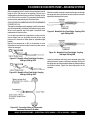
Figure 6. Pumping Cycle 2
In the first cycle, hydraulic pressure is applied to cylinder (B),
causing the hydraulic piston, which is connected to the concrete
piston and piston cup, to discharge concrete into the delivery
line (Figure 5).
As one cylinder is discharging concrete, the hydraulic oil from
the rod side (B) of the drive cylinders is being transferred through
the slave circuit causing the opposite cylinder (A) to move back
on the suction stroke, filling the cylinder with concrete.
The shuttle tube is sequenced to pivot to each concrete cylinder
as the drive cylinders stroke to push concrete. As the second
cycling sequence begins (Figure 6), the shuttle tube pivots to
the opposite cylinder (A). The hydraulic piston passes under the
proximity switch and sends pressure to the piston, causing it to
stroke and discharge concrete into the delivery line. Hydraulic
oil is transfered through the slave circuit to cylinder B, causing it
to start a suction stroke, refilling it with concrete. The pumping
sequence then repeats for the durration of the operation.
Figure 5. Pumping Cycle 1
MAYCO ST-45HRM CE PUMP — OPERATION & PARTS MANUAL — REV. #0 (02/23/04) — PAGE 19
ST-45HRM CE CONCRETE PUMP— PUMP COMPONENTS
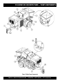
Figure 7. Major Pump Components
PAGE 20 — MAYCO ST-45HRM CE PUMP — OPERATION & PARTS MANUAL — REV. #0 (02/23/04)
ST-45HRM CE CONCRETE PUMP— PUMP COMPONENTS
Figure 7 illustrates the location of the major components
for the ST-45 Structural Concrete Pump. The function of
each component is described below:
1.
Tow Hitch Coupler – See the Towing Information
section in this manual.
2.
Documentation Box – Contains engine and pump
operation, parts and maintenance information.
3.
Hydraulic Oil Tank/Cap– Remove cap to add hydraulic
fluid. Fill with Shell Oil Tellus 68, Mobil Oil DFE26 or
equavalent if hydraulic oil level is low.
13. Lubrication Panel – This console allows for the remote
lubrication of components on the pump.
14. Rear Running Lights – ALWAYS check and make sure
both the right and left running lights are functioning correctly
before towing the pump.
15. Accumulator – Stores hydraulic oil under pressure and
releases it to the shuttle cylinder and provides the
required pressure to activate the hydraulic system.
16. Remixer Control Lever – Controls the forward/reverse
motion of the hopper remixer paddles.
4.
Fuel Tank/Cap – Fill with #2 diesel fuel. Fuel tank (cell)
holds approximately 88 liters (20 gallons). DO NOT top off
fuel. Wipe up any spilled fuel immediately
17. Manifold – Aluminum block that controls the flow of
hydraulic pressure to the various hydraulic motors and other
components required to control the pump.
5.
Battery – This unit uses a +12 VDC type battery. ALWAYS
use gloves and eye protection when handling the battery.
18. Hydraulic Pump – This unit incorporates an axial variable
displacement hydraulic piston pump.
6.
Heat Exchanger – Reduces temperature of the hydraulic
oil. The exchanger draws oil from the hydraulic tank through
a filter and into the heat exchanger before allowing it to
flow into the hydraulic system.
7.
Lubrication Box – This box is empty when shipped
from the factory. Please fill with 7 gallons ( 26.5 liters) of
SAE motor oil for first time use. Also check the dual
clean-out point on bottom of lubrication box for a secure
tight fit.
19. Throttle Control Knob – This is a variable speed type
control. Turning the throttle lock (CCW) left unlocks the
throttle allowing the throttle control cable to be pulled out to
the desired position. Once the desired throttle position
(speed) has been achieved, turning the throttle lock to the
(CW) right locks it in place. Use the fine tune adjustment
knob to fine tune the engine rpm's.
8.
9.
To place the engine in idle, press the top button inward all
the way..
Tires — Tire inflation pressure is the most important factor
in tire life. Pressure should be checked before operation.
DO NOT bleed air from tires when they are hot. Check
inflation pressure weekly during use to insure the maximum
tire life and tread wear.
20. Stroke Volume Control Dial – Turns CW/CCW to increase
or decrease the number of strokes per minute of the pump.
Shuttle Cylinder – Under pressure, the shuttle cylinder
shears concrete passing from the concrete cylinder to
the delivery line durring the cycle phase. The
Accumulator provides the pressure needed to ensure
enough force is provided during cycle.
22. Tow End Jack Stand – Use this jack stand to level and
support the tow end of the pump.
10. Pump End Jack Stand – Use this jack stand to level
and support the rear end of the pump. NEVER deploy
on un-level ground and always check for firmness of
ground.
11. Hopper/Hood – Lift hood to fill. Concrete from a Redi-Mix
truck is poured into this hopper. The hopper can hold 283
liters (10 cu. ft) of concrete with optional forward/reverse
mixer. NEVER put hands or any other parts of you body into
the hopper.
12. Remixer Motor – Drives the remixer paddles inside
the hopper. The motor direction is controled by the
remixer control lever.
21. Control Box – Contains the mechanical and electrical
components required to run the pump. See next page for
control box description.
23. Pumping Pressure Gauge – Used to monitor pressure in
the concrete cylinders and shuttle tube.
24. Accumulator Pressure Gauge– Used to monitor
accumulator pressure. Pressure should read at least 12.1
mPa (1,750 psi) for correct pump operation.
25. Hydraulic Oil Sight Glass – Use to determine the
amount of hydraulic oil remaining in tank. The sight
glass also contains a temperature gauge for monitoring
the temperature of the hydraulic oil.
26. Hopper Discharge Sleeve – Connect hoses or steel
pipes to the discharge sleeve for pouring concrete.
27. Emergency Stop Button – Press emergency stop button
to stop pump in an emergency. Turn knob counter clockwise
to disengage the stop button.
MAYCO ST-45HRM CE PUMP — OPERATION & PARTS MANUAL — REV. #0 (02/23/04) — PAGE 21
ST-45HRM CE CONCRETE PUMP— CONTROL BOX COMPONENTS
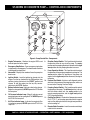
Figure 8. Pump Control Box Components
1.
Engine Tachometer – Monitors the engine RPM’s and
hours of operation for the engine.
2.
Emergency Stop Button – Press emergency stop button
to stop pump in an emergency. Turn knob counter clockwise
to disengage the stop button.
3.
Hourmeter – Display's the number of hours the pump has
been in use.
4.
Ignition Switch – Insert the ignition key here to start the
engine. Turn the key clockwise to the “ON“ position, then
continue turning clockwise to the “START“ position and
release. To stop the engine turn the key fully counterclockwise to the “STOP“ position.
5.
Battery Indicator Lamp– Indicates a low battery charge.
Replace or charge battery. NEVER operate the ST-45 when
this lamp is on.
6.
Oil Pressure Indicator Lamp– When lit, indicates correct
operational pressure for running the ST-45. NEVER operate
the ST-45 if this lamp is off.
7.
Air Filter Indicator Lamp – Indicates the engine air filter
is functioning properly. NEVER operate the ST-45 if this
lamp is off.
8.
Direction Control Switch– This 2 position switch controls
the direction of flow for any mix in the pump. The center
position sets the pumping direction to forward and the right
most position sets the pumping direction to reverse.
9.
Pump Operation Switch– This 2 position switch controls
the operation of the pumping components and engine. The
center position allows the operation of the pump and
engine and the right most position allows only the engine
to operate.
10. Pressure Test Switch– Activates a self-diagnostic routine
which tests the pressure of the pumping system, which can
be read on the Pumping Pressure Gauge.
11. Pumping Control Switch – This 3-position switch controls
the pumping of the pump. The left most position is for use
with the remote control unit, the center position is for
normal pumping operation, and the right most position
(OFF) prevents pumping.
12. Cooling Fan Switch – If hydraulic oil temperature exeeds
23.9° C (75° F), set the pump operation switch to engine
and turn the cooling fan switch to the right most position to
activate cooling fan.
13. Remote Cable Connector – Insert the remote control input
cable into this connector.
PAGE 22 — MAYCO ST-45HRM CE PUMP — OPERATION & PARTS MANUAL — REV. #0 (02/23/04)
ST-45HRM CE CONCRETE PUMP— ENGINE COMPONENTS
Figure 9. Pump Control Box Components
INITIAL SERVICING
The pump's engine (Figure 9) must be checked for proper
lubrication and filled with fuel prior to operation. Refer to the
manufacturers Engine manual for instructions & details of operation
and servicing.
1.
Muffler – Used to reduce noise and emissions. NEVER
touch the muffler while it is hot! Serious burns can result.
NEVER operate the engine with the muffler removed.
2.
Dip Stick – Remove dipstick to determine if the engine oil
level is low. If low add oil as specified in Table 4.
3.
Speed Control Lever – This lever is connected to the
throttle control which is located on the side of the engine
compartment cover. Use this lever to control engine speed.
4.
Oil Filter – Prevents dirt and other debris from entering the
engine. Service the oil filter as recommended in the
maintenance section of this manual.
5.
Side Oil Drain Plug – Remove this plug to drain engine
oil from the engine crankcase. For best results drain engine
oil when oil is warm.
6.
Air Filter/Cover – Prevents dirt and other debris from
entering the fuel system. Release the latches on the side of
the air filter cover to gain access to filter element.
7.
Starter/Solenoid – This engine uses a 12 VDC , 2.7kW
(3.7 HP) starter motor with solenoid.
8.
Front Oil Drain Plug – Remove this plug to drain engine
oil from the engine crankcase. For best results drain engine
oil when oil is warm.
9.
V-Belt Cover – Remove this cover to gain access to the Vbelt. When replacing V-belt , use only recommended type
V-belt.
NOTE
Operating the engine without an air
filter, with a damaged air filter, or a filter
in need of replacement will allow dirt
to enter the engine, causing rapid
engine wear.
MAYCO ST-45HRM CE PUMP — OPERATION & PARTS MANUAL — REV. #0 (02/23/04) — PAGE 23
ST-45HRM CE CONCRETE PUMP— OPERATING PROCEDURES
OPERATING SUGGESTIONS
C. If it is necessary to wait 10 minutes or more for another
load of concrete, it is wise to start the pump and pump
6 or 8 strokes every 5 minutes to prevent setting of the
mix in the system. If waiting time is excessive, it would
be wise to wash out the pump and hoses and start over
when the new truck arrives.
1. A well-planned location of the pump and routing of the hose
before starting a pour may save subsequent moves throughout the job.
2. Before concrete is discharged into the hopper, it is suggested
that 11-4 -15.1 liters (3 to 4 gallons) of water be sprayed into
the hopper, followed by approximately 18.9 liters (5 gallons)
of a creamy cement and water slurry (1/2 bag of cement to
18.9 liters / 5 gallons of water).This procedure lubricates the
hose and prevents separation and blockages in the hose.
D.
E. When the pumping job requires a stiffer mix, the
following method is suggested for starting: Take a
water hose with a nozzle on it and apply water with a
fine spray to the concrete as it comes down the redimix chute into the pump hopper after the slurry
procedure is completed and you are ready to start
pumping.
Getting the concrete to flow through
the hose at the start of the pumping
cycle can be one of the most critical
operations of the pour. (Manually
operate the throttle when starting,
NOT REMOTELY)
NOTE
CAUTION
Using this procedure will make it easier to pump
through the clean hose. Note: Once the concrete has
reached the end of the hose, do not apply any more
water in this manner as this procedure is used for
starting only.
If hoses or lines are blocked for any reason,
or if the lines are kinked when starting up or
during the pumping cycle, the pump
pressure could straighten out the kink or
force out the blockage. This rapid surge of
material could cause the lines to whip or
move in a manner that could cause injury to
personnel.
F. Hose sizing is very important: We strongly recommend on harsh mixes, vertical pushes, stiff concrete,
shotcrete, long pushes, that a 6.35 cm (2 -1/2”) line be
used as far as possible. The advantages of using the
6.35 cm (2 -1/2”) line are improved pumpability, less
pumping pressure and less wear on the pump.
Inspect the lines at all times to prevent the above conditions
3. It is important that once the slurry procedure is completed,
and you have started concrete flowing through the hose, do
not stop the pour until all the slurry is pumped out and the
concrete has reached the end of the hose. The only time to
stop the pump at the start is if a blockage occurs.
5. Following the pump operation, proper wash out of all materials or “build-up” within the pump manifold and hoses will
prevent problems when starting the next job.
6.
4. When the pump is stopped for any reason during a pour; e.g.,
moving hose, waiting for redi-mix truck, the following suggestions are offered:
A. Leave the hopper full of concrete at the time of
shutdown. It is important not to let the redi-mix driver
wash too much water into the hopper, as this could
cause separation of the concrete in the hopper.
B. If the shutdown period exceeds 2 to 3 minutes, turn
off the engine so the vibration does not separate the
mix in the hopper which can cause a blockage in the
manifold when the pump is started.
When pumping stiff mixes and there is waiting time
between redi-mix trucks, it is advisable to add some
water to the last hopper of material and “hand mix” to
ensure an easier start with the following load.
A thorough inspection of the drive components and greasing
of all bearings after each job will ensure adequate lubrication
and service to the pump which is normally operating in wet,
gritty conditions.
NOTE
Over-greasing any bearing on
your Mayco pump will not damage
the bearing.
PAGE 24 — MAYCO ST-45HRM CE PUMP — OPERATION & PARTS MANUAL — REV. #0 (02/23/04)
ST-45HRM CE CONCRETE PUMP— OPERATING PROCEDURES
WARNING
B. MBVR – air entraining, acts as a lubricant.
Common sense tells us that if you drive a
truck into a brick wall, something is going to
be damaged. The same holds true with your
concrete pump. If you repeatedly pull the
throttle all the way out and try to force your
pump to push through blockages due to
separation of material in the hose or manifold, you will soon
have breakdowns and costly repairs which are not covered
under warranty. If a blockage occurs, find where it is and clear it
before further pumping. DO NOT increase the engine speed to
clear the blockage. Increasing the engine speed will only
compound the problem.
C. Calcium Chloride – commonly referred to as C.C., is
used as an accelerator. When pumping a load with
calcium chloride, it is recommended that you wash out
if the waiting time between delivery trucks becomes too
long.
WARNING
It will be necessary at times to move your
pump from one job site location to another.
Before moving the pump, make sure to pump
the remaining concrete out of the hopper.
Moving the pump with a full hopper of
concrete can cause severe damage or
breakage of the axle and axle springs, excess
strain and pressure on the hub and bearing assembly.
Pumping Tips
The effects of heat and excessive time on concrete:
7. Hot concrete, commonly referred to as a hot load, is concrete
that has been in the redi-mix truck in excess of 2 to 3 hours.
On a hot day, this amount of time is even less. A brief
explanation of why heat and time affect concrete:
8. Concrete starts setting by drying up through a chemical
reaction.The catalyst to this reaction is heat. When pumping
a hot load, it is important to remember that when you have to
stop pumping for any reason, add water to the concrete in the
hopper and hand mix and move concrete in the hose every
5 minutes. If the shut down time becomes too long, wash out
immediately.
Admixtures:
9. Remixtures that are designed into the concrete mix by the
redi-mix company or an architectural engineering company.
This section lists common admixtures and a brief explanation of their functions:
A. Pozzolith 300 – or the equivalent acts as a water
retarder and a lubricant. On a lean mix, long pushes, stiff
mixes, and vertical pushes, Pozzolith 300R helps
pumpability.
D. Super Plasticizers – acts as an accelerator. The
concrete will look very wet after the super plasticizer is
added, but will begin to set up very fast. Wash out
immediately if you do not have a truck waiting. Super
plasticizers are used mainly on commercial jobs.
E. Red Label – acts as a water retarder and an accelerator.
Red label will be used mainly on commercial jobs.
F. Fly Ash – is used to help increase the strength of the
concrete and decrease the cement content per yard.
This is one of the most common admixtures used.
NOTE
All admixtures will be shown on the
redi-mix concrete ticket. Before starting the pumping job, ask the driver of
the redi-mix truck to see the concrete
ticket and note the admixtures that
exist and take the proper action.
10. When pumping long distance or pumping stiff mixes, you can
expect a drop in volume compared to shorter lines and wetter
mixes due to the change in valve efficiency or cavitation.
11. Leaking manifold seals or hose coupling gaskets which leak
water can cause separation and subsequent jamming at that
point.
Priming the Pump and Delivery System with Slurry
12. It is CRITICAL to the successful operation of a concrete
pump that the manifold and all delivery hose, pipe and
elbows are coated with a film of lubrication BEFORE you
attempt to pump concrete. Failure to properly prepare the
pump and system will result in a “dry pack” of concrete,
blocking the shuttle valve tube or delivery line.
A. With the entire delivery system connected to the pump.
Except for the first hose. Pour 18.9 liters (5 gallons) of
water into the second hose and push in your clean out
ball and reconnect. This will help hold back the prime.
B. There are several things you can use for the prime. A
few examples are Cement and lime at a 50/50 mixture,
slick pac, bentonite clay.
MAYCO ST-45HRM CE PUMP — OPERATION & PARTS MANUAL — REV. #0 (02/23/04) — PAGE 25
ST-45HRM CE CONCRETE PUMP— OPERATING PROCEDURES
C. Mix the prime to the consistency of a smooth batter.
D. Position the first ready-mix truck at the hopper. Check
the concrete. DO NOT discharge concrete into hopper
at this time.
The bentonite is not compatible with
concrete. DO NOT pump it into the
forms. Discharge it out of the formed
area.
NOTE
16. The shuttle tube is plugged if volume at the discharge end of
the hose stops, the hose is soft and the hydraulic oil pressure
gauge reads 20.7 mPa (3000) psi or more.
To clear a plug in the shuttle tube, great care must be taken
as a dangerous condition will exist from pressure build-up
inside the shuttle tube. (With the shuttle valve, the concrete
can be pumped in reverse.) Use the following prodedures
to clear the shuttle tubes.
WARNING
E. Pour approximately two 18.9 liter (5 gallon) buckets of
prime into the first hose and connect it to the pump.
F. With the pump in FORWARD at 25-30 strokes per
minute, slowly discharge the concrete from the readymix truck into the hopper and completely fill it. Keep the
pump running continuously until concrete is discharging
at the end of the delivery system. If the pump is stopped
during this procedure, a blockage may occur.
G. If it is necessary to replace or add a section of delivery
system, after the initial lubrication procedure, wet the inside
area of the hose, pipe or elbow with 18.9 liters (5 gallons)
of water per 7.62 meters (25 ft.) length, before adding it to
the system.
Clearing Concrete Blockage
13. Damaged hoses with internal restrictions can cause blockages.
14. If a blockage occurs in a hose, walk the hose until you find
the point of trouble.The hose will be soft immediately past the
blockage. If this happens at the start, disconnect the hose at
the first coupling past the blockage.
15. Elevate the hose at that point with the blockage area hanging
down. Using a hammer, you can pound the down-stream
edge of the packed area until it is free to flow. Shake all of the
sand and gravel out to the end of the hose. Before reconnecting the hose, start the pump and run a small amount of
concrete out to the end of the hose. This will assure that all
of the separation is out of the hose.
CAUTION
Use extreme care! The hose line is under
pressure and can cause serious injury.
DO NOT open any of the
delivery system joint clamps.
“Reverse” Pumping Procedure
A. Switch the pump into reverse. With pump speed at a
medium-slow (approx. 12 strokes per min.) try to pull
the “pack” back into the hopper with 5 or 6 reverse
strokes.
B. Remix the concrete in the hopper.
C. Switch the pump into forward. If it is still plugged, repeat
“Reversing” procedure three times.
If concrete still does not move, proceed to the Shuttle Tube
Inspection Procedure.
Shuttle Tube Inspection Procedure
A. Stop the pump. Switch off the engine.
B
The senior or most experienced operator must warn all
others to stand at least 6.1 meters (20 feet) away from
the machine and turn their heads to face away from the
pump.
CAUTION
Saftey glasses MUST be worn at all times
when operating the ST-45. Failure to follow saftey guidlines can result in serious
injury.
C. The operator will position themself beside the reducing
elbow at the pump outlet. Wearing safety glasses,
slip the end of a pry bar (61 cm/24" length of reinforcing
steel rod) under the latch of the hose clamp and flip it
up.
PAGE 26 — MAYCO ST-45HRM CE PUMP — OPERATION & PARTS MANUAL — REV. #0 (02/23/04)
ST-45HRM CE CONCRETE PUMP— OPERATING PROCEDURES
D. Carefully knock the end of the hose away from the
reducer.
E. Chip the concrete out of the reducer with the pry bar.
F. Remove the reducer. From the discharge end, chip the
concrete out of the shuttle tube with the pry-bar. If
concrete cannot be loosened from the outlet of the
shuttle tube, remove the clean-out plug on the bottom
of the hopper to discharge the concrete.
G. The senior operator may then remove the inspection
cover plate from the shuttle tube by using a long
extension wrench and the 61 cm (24-inch) pry bar.
WARNING
Make sure the accumulator pressure gauge
reads ZERO psi. prior to performing any
maitinance or inspection.
H. Chip the blockage out with the pry-bar.
I.
Flush the shuttle tube with water.
J. Replace and seal the inspection cover plate on the
shuttle tube.
K. Before resuming operation of the pump, perform the
“Reverse” Pumping Procedure to relieve pressure on
the shuttle tubes.
17. If it is necessary to wait 1/2 hour or more for another load
of concrete, and to prevent setting of the mix in the system,
it is advisable to consider the following factors
(A through D) affecting the concrete :
A. How old is the concrete?
B. Is there an accelerator, calcium chloride, red label, etc.,
in the concrete?
C. Temperature of the day, 27° C (80° F), 32° C (90° F)?
D. How much system you have out and how stiff was the mix
you were pumping?
NOTE
When disconnecting hoses, use
EXTREME CAUTION! The hose is
under pressure!
If, for any reason, the mix should set up in the system, the
following procedure (E through H) is suggested:
E. Disconnect the hose from the pump and wash the pump
out immediately.
F.
Reconnect the hose and fill the hopper with water.
G. Reconnect the hose and fill the hopper with water. DO
NOT try to push all the concrete out of all of the hose
lines at one time.
For example: If you had 61 meters (200 ft.) of system out,
you would disconnect each hose. Clean it out by pushing water through the first hose off the pump, then
continue progressing through all the hoses, until all the
system is clean.
H. If waiting time is excessive, it would be wise to wash out
the pump and hoses and start over when the new truck
arrives. This can be avoided by being observant to the
pump and system, also taking into consideration the
above factors (E through H) affecting the mix.
18. Down-Hill Pumping – can be difficult on some jobs. The
slurry procedure would be the same as explained on the
pages titled Operating Suggestions. It is suggested that a
sponge 5 cm x 10 cm x 15 cm (2”x 4”x 6”) be placed in the
hose before the start of pumping. Wet the sponge before
placing it in the hose.
The reason for using the wet sponge is to keep the slurry from
running too far ahead of the concrete and so reducing the
possibility of separation. When the pump is stopped, the
material can flow slowly down, due to gravity, and cause the
hose to collapse.
When pumping is resumed, you can expect blockage at the
point of hose collapse. To prevent this from happening, the
hose can be “kinked off” at the discharge end when the pump
is stopped to prevent the gravity flow of the material in the
hose.
The use of stiffer mixes when pumping down-hill will decrease gravity flow of the material in the hose and will assure
a smoother operation between the cam roller bearing and
cam plate. As with any job, make sure that the hose and the
couplings are in good workable shape.
MAYCO ST-45HRM CE PUMP — OPERATION & PARTS MANUAL — REV. #0 (02/23/04) — PAGE 27
ST-45HRM CE CONCRETE PUMP— OPERATING PROCEDURES
19. Vertical Pumping – When pumping vertically up the side of
a building, above 12.2 meters (40 feet), we would recommend the installation of steel pipe securely fastened at
intervals as necessary to support the pipe. Ninety degree,
long radius pipe sweeps should be installed at the top and
bottom of the steel line.
Use a 7.62 meter (25 ft.) hose, or short section, off the pump;
and for the balance of the horizontal distance to the vertical
line, use steel pipe. This type of installation has been satisfactory on many jobs being pumped in excess of 30 meters
(100 feet) high. Line pressures are always less using steel
pipe as compared to hose.
When pumping vertically, using all hose, it is recommended
not to go higher than 7.62 meters (50 feet) with hose.The hose
should be tied off at intervals of 3 meters (10 feet), if possible.
Special attention should be given when tieing the hose off at
the top as the hose will have a tendency to stretch when filled
with concrete.This will increase the possibility of a blockage
at the point where the hose is tied off. To avoid this, a long
radius of 90 degree elbow is recommended. The suggested
place to tie off is on the hose, under the clamp.
NOTE
It is strongly recommended that
steel pipe be used on all vertical
pumping for safety and convenience.
20. Pulsation – A slight pulsation of the hose will always be
noticeable near the pump. Excessive pulsation of the hose
near the pump is normally due to higher than average line
pressures caused by stiff, harsh mixes, or extremely long
pumping distances.
The use of 63.5 mm (2 -1/2” ) I.D. hose in these extreme cases
reduces line pressures or the addition of slight amounts of
water to the mix, if permissible, will permit easier pumping.
The use of certain pumping admixtures may help.
If excessive pulsation exists in the hose, it is advisable to use
burlap or some means of wear protection under the hose at
points where the hose may wear through the outer cover; e.g.
over forms, steel or sharp curbs.
21. Snap-Joint – When using Snap-Joint couplings with gaskets to join hose, see that they are washed clean after each
job. Keeping the hose ends clean (heavy duty) is very important for the best job setup. A thin coat of grease on the rubber
gasket or dipping both coupling and gasket in water before
coupling the hose will make for easier installation.
22. New Pumps – All new pumps are ‘water pressure tested” at the
factory This procedure permits a thorough inspection of entire
drive system and valving under simulated full load conditions.
The pump owner can do the same by making an adapter to
couple to the end of the discharge cone: e.g., the use of a standard
51 mm (2-inch) pipe cap with a 9.5 mm (3/8") drilled hole in the
center, screwed on to the end of hinged cone or reducer at the
pump.
Fill hopper with water after making sure that all sand and rock
have been removed from manifold. Operate pump at full
throttle and the 9.5 mm (3/8") diameter hole restriction will
create sufficient back pressure to make thorough inspection
of all moving parts.
PAGE 28 — MAYCO ST-45HRM CE PUMP — OPERATION & PARTS MANUAL — REV. #0 (02/23/04)
ST-45HRM CE CONCRETE PUMP— INSPECTION
CAUTION
NEVER operate the pump
in a confined area or
enclosed area structure
that does not provide
ample free flow of air.
FUEL CHECK
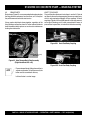
5. Read the fuel sight tube (Figure 10) on top of the fuel tank
to determine if the pump's engine fuel is low .
ALWAYS wear approved eye and hearing
protection before operating the pump .
NEVER place hands or feet inside the hopper. ALWAYS shutdown the engine before performing any kind of maintenance on
the pump.
NEVER operate the pumps's engine with the
engine hood or V-belt cover removed. The
possibility exists of hands, long hair, and
clothing becoming entangled with the V-belt,
causing injury and bodily harm.
Reference Figures 7 through 9 for
the location of any control or
component referenced in this section.
NOTE
Figure 10. Fuel Sight Tube
Before Starting
1. Read safety instructions at the beginning of manual.
6.
If fuel is low, remove fuel filler cap and fill with #2 diesel
fuel (Figure 11).
2. Clean the entire pump, removing dirt and dust, particularly
the engine cooling air inlet, and air filter.
3. Check the air filter for dirt and dust. If air filter is dirty, replace
air filter with a new one as required.
4. Check fastening nuts and bolts for tightness.
CAUTION:
Handle fuel safely. Diesel fuel is highly
flammable and can be dangerous if
mishandled. DO NOT smoke while refueling.
DO NOT attempt to refuel mixer if the engine is
hot or running. ALWAYS allow engine to cool
before refueling.
Figure 11. Adding Diesel Fuel
MAYCO ST-45HRM CE PUMP — OPERATION & PARTS MANUAL — REV. #0 (02/23/04) — PAGE 29
ST-45HRM CE CONCRETE PUMP— INSPECTION
ENGINE OIL CHECK
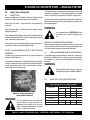
7. Remove the engine oil dipstick from its holder (Figure 12).
12 The oil listed in Table 4 is recommended to ensure better
engine performance. Use class CD or higher grade motor
oil.
Figure 12. Engine Oil Dipstick
8. Make sure pump is placed on level ground.
9. Pull the engine oil dipstick (Figure 13) from its holder.
Hydraulic Oil
13. Determine if the hydraulic oil level is low by observing the
level of the oil in the Hydraulic Oil Sight Glass (Figure 14).
Figure 14. Hydraulic Oil Sight Glass
Figure 13. Engine Oil Dipstick
10. Verify that oil level (Figure 13) is maintained between
the two notches on the dipstick.
11. If the pump's engine oil is low, fill engine crankcase
with lubricating oil through filler hole, but DO NOT overfill.
PAGE 30 — MAYCO ST-45HRM CE PUMP — OPERATION & PARTS MANUAL — REV. #0 (02/23/04)
ST-45HRM CE CONCRETE PUMP— INSPECTION
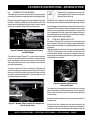
14. If the hydraulic oil level is low, remove the cap just above the
oil level sight glass (Figure 15) and add the correct amount
of hydraulic oil to bring the hydraulic oil level to a normal
safe operating level. (Use Shell oil Tellus 68 or Mobil oil
DFE26).
16. Remove the cotter pin from the handle tee bolt eye, and
then pull the handle tee to release the stabilizer stand (Figure
17).
17. Position both rear stabilizers stands on firm (not loose) level
ground (Figure 18).
18. Align the hole on the stabilizer stand with the hole on the
frame body and insert handle tee bolt.
19. Insert the cotter pin into handle tee bolt eye to lock the
stabilizer stand.
Figure 15. Hydraulic Oil Filler Hole
REAR STABILIZER STAND
To reduce excessive vibration and rocking of the ST-45 Concrete
Pump, set the rear stabilizers as follows:
Figure 17. Rear Stablizer Stand
15. Locate both the left and right rear stabilizer stands
(Figure 16).
Figure 18. Rear Stablizer Stand Deployment
Figure 16. Locatiing Rear Stabilizer Stands
MAYCO ST-45HRM CE PUMP — OPERATION & PARTS MANUAL — REV. #0 (02/23/04) — PAGE 31
ST-45HRM CE CONCRETE PUMP— INITIAL START-UP PROCEDURE
IGNITION SWITCH
STARTING
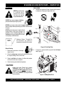
CAUTION :
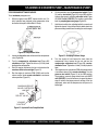
3. To start the engine, insert the key (Figure 20) into the ignition
switch and turn the key to the ON position.
DO NOT attempt to operate this concrete
pump until the Safety, General Information
and Inspection sections have been read and
understood.
EMERGENCY STOP SWITCH
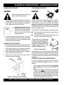
1. There are 2 emergency stop switches (Figure 19). One is
located on the the control box, the other is located on the
other side of the pump near the heat exchanger. Both are
provided for operator safety. In the event of an emergency,
press either stop switch to stop the engine.
Figure 20. Ignition Switch
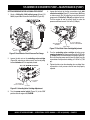
4. Observe that the Air Filter and Oil Pressure status indicator
lights are “ON” (Figure 21). The Battery status indicator light
should be “OFF.”
Figure 19. Emergency Stop Switch
2. Turn both Emergency Stop switches counter-clockwise
(open). This will allow the engine to start.
Figure 21. Status Indicator Lights
NOTE
If either one of the Emergency Stop
switches is in the “CLOSED” position
(stop), the engine will not start. To start
the engine, make sure that both
Emergency Stop switches are in the
“OPEN” position (fully extended).
A. Turn the key to the “START“ position and listen for the
engine to start.
B. In warm weather let engine warm-up for 5 minutes. In
cold weather let engine warm-up for 10 minutes.
C. The Air Filter, Oil Pressure and Battery indicator lights
(Figure 21) should all be “OFF”.
NOTE
NOTE
Place all switches on the Hydraulic
Control Box in the ”OFF” (up position).
If any of the status indicator lights
referenced in the ignition section
(step 4) are “ON”, turn off the engine.
DO NOT continue to run the engine.
PAGE 32 — MAYCO ST-45HRM CE PUMP — OPERATION & PARTS MANUAL — REV. #0 (02/23/04)
ST-45HRM CE CONCRETE PUMP— INITIAL START-UP PROCEDURE
CONTROL SWITCH
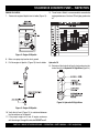
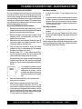
5. Turn the Pump Control switch (Figure 22) to
the “ON” position, a thumping sound
(cylinder stroke) should be heard. The
thumping sound represents the number of
strokes per minute (volume) of the pump.
Figure 22. Pump Control Switch
6. Turn the Volume Control (Figure 23), lock nut
counterclockwise (CCW) to release the volume control
knob.
8. While monitoring the tachometer,
(Figure 25) use the Engine
Throttle Control to set the engine
speed to 1500 RPM by following
steps 8A-8C.
Figure 25. Engine
Tachometer
A. Unlock the throttle cable. To unlock the throttle cable, turn
the inner most knob counter clockwise (Figure 26.)
THROTTLE
ADJUSTMENT
KNOB (COARSE)
(PUSH/PULL)
UNLOCK
UNLOCKING
KNOB
LOCK
THROTTLE
ADJUSTMENT
KNOB (FINE)
(TURN CW/CCW)
Figure 26. Throttle Control Knob (Un-locking)
Figure 23. Volume Control
6. Use the volume control, to set the
pump volume to approximately 10
strokes per minute. Turning the
volume control clockwise (CW)
will decrease pump volume,and
counterclockwise (CCW) will
increase pump volume.
B. Push the outermost button, Figure 27 (coarse adjustment) inward, then pull outward until engine RPM
reaches desired speed.
C. Turn the unlocking knob (figure 26) clockwise to lock
engine RPM in place.
PUSH-IN, THEN PULL
TO SET THROTTLE
(RPM’s)
Figure 24. Hydraulic Oil Temperature Gauge
7. Let the pump cycle until the hydraulic oil temperature
(Figure 24) is approximately 10°-15.6° C (50°- 60° F)
NOTE
Use a wristwatch or stop watch to
determine the number of pump
strokes within 1 minute.
PUSH ALL THE WAY IN
TO IDLE ENGINE
Figure 27. Throttle Control Knob (RPM Adjust)
9. Turn the Control Off switch (Figure 22) to the “OFF“ position.
MAYCO ST-45HRM CE PUMP — OPERATION & PARTS MANUAL — REV. #0 (02/23/04) — PAGE 33
ST-45HRM CE CONCRETE PUMP— INITIAL START-UP PROCEDURE
ENGINE SPEED
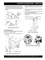
10. Turn the Operation Pump/Engine switch
to the “ENGINE” position (Figure 28).
13. Make sure the Operation Pump/Engine
switch is in the “ENGINE“ position
(Figure 28), and that only the engine is
running.
Figure 28. Operation Pump Engine
Switch
14. Turn the fan switch (Figure 30) to the “ON“
position and listen for fan to start.
Figure 30. Fan On/Off Switch
The pump should not be cycling at this
time. Only the ENGINE should be
running.
NOTE
11. While monitoring the tachometer
(Figure 25), use the Engine
Throttle Control to set the
engine speed to 2550 RPM
(maximum speed) using steps
8A-8C
12. The Accumulator Pressure
Gauge (Figure 29) should read
approximately 12.1 mPa (1,750
psi).
15. Turn the fan switch to the “OFF“ position and listen for fan
to stop. If machine exceeds 170°F or to cool the machine
down, turn the operation switch (Figure 28) back to the
“ENGINE“ position. Run engine at high RPM with cooling
fan on for 10 to 15 minutes.
PRESSURE TEST
16. The Pressure Test switch (Figure 31) is a
self-diagnostic test switch, that when
activated will test the pressure of the system.
This switch will be discussed in the
maintenance and troubleshooting section
of this manual.
Figure 31. Pressure Test On/Off Switch
Figure 29. Accumulator Pressure Gauge
HOPPER REMIXER CONTROL
COOLING FAN
This section is intended to make sure the fan is working properly.
Under normal conditions the fan should be turned on when the
hydraulic oil temperature begins to approach 23.9° C (75° F).
A. Located to the left of the Hydraulic Temperature gauge is
the Hopper Remixer Control lever (Figure 32).
B. Turn the Operation Pump/Engine switch to the “ENGINE“
position (only the engine should be running).
CAUTION
If the hydraulic oil temperature exceeds
76.7° C (170° F), shut down the pump.
DO NOT continue to operate the pump.
Failure to shut down the pump will result in
severe damage to the pump.
Figure 32. Hopper Remixer Control Lever
PAGE 34 — MAYCO ST-45HRM CE PUMP — OPERATION & PARTS MANUAL — REV. #0 (02/23/04)
ST-45HRM CE CONCRETE PUMP— INITIAL START-UP PROCEDURE
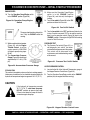
C. Push the Hopper Remixer Control lever “DOWNWARD“
(Figure 32) and observe that the blades (Figure 33) inside
the hopper are turning in a clockwise direction (forward).
Figure 35. Handheld Remote Cable Unit
Figure 33. Hopper Remixer Blades (Rotation)
CYLINDER LUBRICATION BOX
WARNING
D. Push the Hopper Remixer Control lever “UPWARD“ (Figure
32) and observe that the blades (Figure 33) inside the
hopper are turning in a counter-clockwise direction
(reverse).
Before checking lubricaton level, stop the
engine and remove the engine starter key.
We recommend using soluble type oil (water
& oil mixture). The oil level should be
checked every day prior to pumping. The oil
level should be maintained at a height of 12.7
cm (5 inches) or about half the concrete
cylinder height.
OPTIONAL RADIO REMOTE CONTROL
14. The MAYCO ST-45 Concrete Pump has a remote control
feature that allows the pump to be remotely controlled. If
desired, the pump can be operated via a receiver/transmitter
method (Figure 34) or a hardwire method, which utilizes a
7.62 meter (25-ft.) extension cable. The manual remote
cord (Figure 35) should be installed under the main control
box. Contact your MAYCO/MULTIQUIP representative for
further information.
NOTE
Important Notice! During freezing
temperature after pumping, completely
drain the water box and cover the
hopper. Frozen liquid will restrict the
piston travel and cause severe
damage to the pump.
15. As the rubber piston cups naturally wear, fine cement
particles will accumulate in the box. Once the concrete paste
reaches a height of about 1.3 cm (1/2-inch) from the bottom.
The box should be drained and cleaned. To clean, remove
the drain plug located at the bottom of the box.
Once the box is drained, start the engine and stroke the
cylinder (keep hands out of box) ten to fifteen times. While
stroking, spray water inside of the box to thoroughly clean
out all contamination. When the box is clean, replace drain
plug, add new lubrication and install the top cover.
Figure 34. Handheld Receiver/Transmitter
MAYCO ST-45HRM CE PUMP — OPERATION & PARTS MANUAL — REV. #0 (02/23/04) — PAGE 35
ST-45HRM CE CONCRETE PUMP— TRAILER SAFETY GUIDELINES
Tires/Wheels/Lug Nuts
Tires and wheels are a very important and critical
components of the trailer. When specifying or replacing the
trailer wheels it is important the wheels, tires, and axle are
properly matched.
CAUTION
DO NOT attempt to repair or modify a wheel.
DO NOT install an inter-tube to correct a
leak through the rim. If
the rim is cracked, the
air pressure in the
inter-tube may cause pieces of the rim to
explode (break-off) with great force and
can cause serious eye or bodily injury.
Tires Wear/Inflation
Tire inflation pressure is the most important
factor in tire life. Pressure should be
checked cold before operation. DO NOT
bleed air from tires when they are hot.
Check inflation pressure weekly during
use to insure the maximum tire life and
tread wear.
Table 5 (Tire Wear Troubleshooting) will help
pinpoint the causes and solutions of tire wear
problems.
NOTE
ALWAYS wear safety glasses when
removing or installing force fitted
parts. Failure to comply may result in
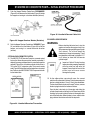
serious injury.
Lug Nut Torque Requirements
It is extremely important to apply and maintain proper wheel
mounting torque on the trailer. Be sure to use only the fasteners
matched to the cone angle of the wheel. Proper procedure for
attachment of the wheels is as follows:
1. Start all wheel lug nuts by hand.
2. Torque all lug nuts in sequence. See Figure 36. DO NOT
torque the wheel lug nuts all the way down.Tighten each lug
nut in 3 separate passes as defined by Tables 6 and 9.
Table 6. Lug Nut Torque Requirements
Wheel Size
First Pass
N-m/FT-LBS
Second Pass
N-m/FT-LBS
Third Pass
N-m/FT-LBS
30.5 cm/12"
27.1-33.9/
(20-25)
47.4-54.2/
(35-40)
67.8-88.1/
(50-65)
33.0 cm/13"
27.1-33.9/
(20-25)
47.4-54.2/
(35-40)
67.8-88.1/
(50-65)
35.6 cm/14"
27.1-33.9/
(20-25)
67.8-81.3/
(50-60)
122-162.7/
(90-120)
38.1 cm/15"
27.1-33.9/
(20-25)
67.8-81.3/
(50-60)
122-162.7/
(90-120)
40.6 cm/16"
27.1-33.9/
(20-25)
67.8-81.3/
(50-60)
122-162.7/
(90-120)
3. After first road use, retorque all lug nuts in sequence. Check
all wheel lug nuts periodically.
NOTE
NEVER! use an pneumatic air gun
to tighten wheel lug nuts.
PAGE 36 — MAYCO ST-45HRM CE PUMP — OPERATION & PARTS MANUAL — REV. #0 (02/23/04)
ST-45HRM CE CONCRETE PUMP— TRAILER SAFETY GUIDELINES
Figure 36. Wheel Lug Nuts Tightening Sequence
MAYCO ST-45HRM CE PUMP — OPERATION & PARTS MANUAL — REV. #0 (02/23/04) — PAGE 37
ST-45HRM CE CONCRETE PUMP — TOWING INFORMATION
RUNNING GEAR MANUFACTURERS
Broadway Industrial Estate, Hyde, Cheshire SK14 4QF
Telephone: 0161 368 6414 Fax: 0161 367 8702
Email: enquiries@ meredithandeyre. co.uk
RECOMMENDED MAINTENANCE
& SERVICE INFORMATION
T CHASSIS
SUSPENSION AXLES
AUTO-REVERSE COUPLINGS
GENERAL TRAILER INFORMATION
PAGE 38 — MAYCO ST-45HRM CE PUMP — OPERATION & PARTS MANUAL — REV. #0 (02/23/04)
ST-45HRM CE CONCRETE PUMP— TOWING INFORMATION
1.0 GENERAL INFORMATION
In
. order to maintain the function and safety of your trailer, only
original parts of the manufacturers design must be used. Servicing
should only be undertaken by qualified personnel.
1.1
TOWING LEVEL
Ideally, the trailer should be towed level (Figure 37) and not with
the draw bar leaning up or down excessively. Some countries
allow ± 4° from the level (approximately ±100mm) but in others
it remains at the discretion of the user for safe operating conditions
1.3
TYRES AND WHEELS
Within the EC, tyres must be marked with a load index (LI) and
speed symbol, which designate the maximum carrying capacity
per tyre at the maximum speed. See Tables 7 and 8.
For trailer use, car tyres may be given a bonus loading of 5%
and commercial van tyres 10% due to the reduced speed limits
that apply to trailers (in the UK 97 kmh/60 mph). However, we
would generally recommend working within the load index
designation to allow for the possibility of operation over the
normal speed limitations.
TABLE 8. SPEED SYMBOLS
Speed Symbol
F
G
J
K
L
M
N
P
Q
R
Max MPH
50
56
62
68
75
81
87
93
100
106
Max KMH
80
90
100
110
120
130
140
150
160
170
Figure 37. Towing Level
1.2
CAPACITIES
For safety, warranty and legal reasons, DO NOT exceed the
maximum allowable fully laden mass.
The maximum tyre pressure marked on the tyre is usually
compatible with the load index and speed symbol. If in doubt,
check with the manufacturer or with us.
On a trailer’s drawbar assembly, there may be 3 ore more labels/
stampings stating the maximum masses and other parameters.
It is important to be aware that the label or stamping stating the
lowest maximum gross mass overrules all others; generally the
label affixed to the body of the trailer by the trailer or plant
manufacturer states the actual maximum, as this will allow for
wheel and tyre capacities.
TABLE 7. TYRES LOAD INDEX
LI
Kg
LI
Kg
LI
Kg
LI
Kg
LI
Kg
LI
Kg
LI
Kg
67
307
78
425
89
580
100
800
111
1090
122
1500
133
2060
68
315
79
437
90
600
101
825
112
1120
123
1550
134
2120
69
325
80
450
91
615
102
850
113
1150
124
1600
135
2180
70
3 35
81
462
92
630
103
875
114
1180
125
1650
136
2240
71 345
82
475
93
650
104
900
115
1215
126
1700
137
2300
72
355
83
487
94
670
105
925
116
1250
127
1750
138
2360
73
365
84
500
95
690
106
950
117
1285
128
1800
139
2430
74
375
85
515
96
710
107
975
118
1320
129
1850
140
2500
75
387
86
530
97
730
108
1000
119
1360
130
1900
141
2575
76
400
87
545
98
750
109
1030
120
1400
131
1950
142
2650
77
4 12
88
560
99
775
110
1060
121
1450
132
2000
143
2725
MAYCO ST-45HRM CE PUMP — OPERATION & PARTS MANUAL — REV. #0 (02/23/04) — PAGE 39
ST-45HRM CE CONCRETE PUMP— TOWING INFORMATION
1.4
CONNECTION TO TOWING VEHICLE
First, check the compatibility of your 50mm Ball Coupling or
Towing Eye with the Towing Jaw/Ball connection on your vehicle.
Always fit the breakaway cable or safety chain in a loop, fastening
back on itself, to a substantial integral point on the towing vehicle.
Ensure that the effective length is as short as possible, but still
allows articulation (e.g. for cornering) without applying the brakes
or tension through the chains.
WARNING
We DO NOT recommend the use of safety
chains and a breakaway cable (Figures 38
and 39) at the same time.
Figure 38. Breakaway Cable
2.0 ROUTINE CHECKS
2.1
VISUAL INSPECTION
Regular visual inspections will usually identify accidental
damage if conducted systematically.
2.2
TYRE DAMAGE
It is dangerous to neglect tyre damage, and should a blister,
rupture or cut to be detected, exposing the casing, or the tyre
suffers a violent impact (e.g. against a curb) such that there is a
risk of internal damage, it is advisable to have the tyre examined
by ah specialist as soon as possible.
2.3
WHEEL DAMAGE
Wheels damaged or distorted, or having wheel nut/bolt sea tings
cracked or deformed must not be repaired or used in service.
Warning: If the wheel is damaged, it is possible that the brake
drum, stub axle or complete axle may have been damaged, so
investigate further.
2.4
TOWING EYE, BALL HITCH & DRAWBAR
ATTACHMENT
Gripping the towing eye or ball in both hands, pull back and
forth, up and down, feeling for excessive movement. Replace
any parts that are bent or deformed in anyway. Check the
attachment of the coupling body to the drawbar and of the drawbar
to the trailer/machine.
2.5
HAND BRAKE
Apply hand brake checking operation and effectiveness. If in
doubt re-adjust braking system (see section 3.2)
Figure 39. Safety Chains
LEGAL
NOTE
It is legal to use safety chains up
to a maximum gross trailer mass
of 1500 kg.
PAGE 40 — MAYCO ST-45HRM CE PUMP — OPERATION & PARTS MANUAL — REV. #0 (02/23/04)
ST-45HRM CE CONCRETE PUMP— BRAKING SYSTEM
3.0 BRAKING SYSTEM
3.1
WHEEL JACKING
On level ground, with the hand brake lever in the off position and
overrun coupling draw tube shaft fully extended forwards, secure
one wheel with wheel chocks. Position your jacking device behind
the opposite wheel, as near to a main longitudinal chassis
member as possible. Lift the wheel clear of the ground and secure
with suitable axle stands.
NOTE
If not already connected, connect the
Bowden (sheathed) cables to the
brakes.
3.2
BRAKING SYSTEM ADJUSTMENT
Where the transmission rod and brake cables are already
connected, take the tension out of the system by winding back
the nuts on the rod behind the compensator.
It is now possible to begin the setup procedure:
3.3
WHEEL BRAKES
These can be adjusted by means of a 17mm, 19mm, or 24mm
AF Spanner (dependant on brake type) on the adjuster bolt head
at the rear of the brake back plate. Reference Figures 40A, B
and C.
Figure 40B. Connecting Sheated Cable
Adjuster Bolt
Figure 40A. Adjuster Bolt
Figure 40C. Connecting Sheated Cable
Rotate each wheel only in the forward direction of travel, whilst
tightening the bolt until the wheel locks. Then, gradually back off
the adjuster nut until the wheel can rotate forwards with just a
slight resistance/audible brushing of the brake drum on the brake
linings (this is best adjusted with the wheel and tyre fitted to the
brake drum).
MAYCO ST-45HRM CE PUMP — OPERATION & PARTS MANUAL — REV. #0 (02/23/04) — PAGE 41
ST-45HRM CE CONCRETE PUMP — BRAKING SYSTEM
3.4 COUPLING AND TRANSMISSION SYSTEM
Attach the opposite end of the outer cable to the anchor plate
(Figure 41E) on the axle or draw bar, using the nut provided.
Connect the inner cables to the compensator, locking the 2 plain
nuts together in front of the compensator for each cable. If not
already connected, attach the rear end of the brake rod to the
compensator center hole.
COUPLINGS WITH HANDBRAKE MOUNTED ON COUPLING
BODY (FIGURES 41A-41E)
Use the plain nuts behind the compensator to adjust, until the
overrun output lever can be pulled rearwards by firm hand
pressure (not loose) a maximum of 14mm (16mm for adjustable
height models.) For knott couplings, there should not be any
movement
Figure 41C. Meredith & Eyre Handbrake Applied
NOTE
Spring Store now compressed
Maintain the compensator at 90° to the draw bar for even
distribution of force into each cable. Ensure the cables are not
“kinked” or damaged.
Figure 41D. Meredith & Eyre Handbrake After Automatic
Activation In the Reverse Mode
NOTE
Spring Store now extended, handbrake will
feel less tensioned.
Figure 41A. Meredith & Eyre Fixed Height Coupling up
to 2500 kg GVM
Figure 41B. Meredith & Eyre Fixed Height Coupling up
to 2000 kg GVM
Figure 41E. Connecting Cables to Compensator
Handbrake Mounted On Coupling Body
PAGE 42 — MAYCO ST-45HRM CE PUMP — OPERATION & PARTS MANUAL — REV. #0 (02/23/04)
ST-45HRM CE CONCRETE PUMP— BRAKING SYSTEM
With the handbrake fully off, check that the spring store’s overall
length is 185 to 190 mm and is not applying a force to the U
shaped guide on the side of the overrun lever. Adjusting is by the
nut at the front of the assembly. This procedure should only be
necessary when replacement parts have been fitted.
With these models, the brake transmission linkage runs through
the spring store, which must be set correctly to achieve automatic
operation tensioning of the system.
COUPLINGS WITH HANDBRAKE MOUNTED ON DRAW BAR
(FIGURES 41F-41J)
The setup for the higher capacity couplings is similar to the above,
with the exception of the setting of the handbrake spring store,
which is more powerful due to the higher transmission force
requirements for heavier trailers.
Figure 41I. Meredith & Eyre Fixed Height Coupling 2500
kg to 3500 kg GVM
Use the plain nuts behind the compensator to adjust, until the
overrun output lever can be pulled rearwards by firm hand
pressure to a maximum of 18mm (8mm for adjustable height
models).
Maintain the compensator at 90° to the drawbar for even
distribution of force into each cable. Ensure the cables are not
“kinked” or damaged.
Figure 41J. Meredith & Eyre Fixed Height Coupling
2200 kg to 3500 kg GVM
Figure 41F. Meredith & Eyre Fixed Height Coupling
2500 kg to 3500 kg GVM
Leave the handbrake and spring store connector loose while
setting the overrun system as previously described. Finally, pull
the spring store up to the hexagonal adaptor by sliding the spring
and bracket forward. Tighten the three locking nuts on the
connector.
Figure 41G. Meredith & Eyre Fixed Height Coupling
2200 kg to 3500 kg GVM
Figure 41H. Connecting Cables to Compensator
Handbrake Mounted On Drawbar
MAYCO ST-45HRM CE PUMP — OPERATION & PARTS MANUAL — REV. #0 (02/23/04) — PAGE 43
ST-45HRM CE CONCRETE PUMP — BRAKING SYSTEM
3.5
BRAKE PARTS
KNOTT COUPLINGS
Brake shoes (Figure 42) are recommended to be replaced when
the lining thickness measures less than 2mm, as it is likely that
they will be worn out before the next service.
Always replace both brake shoes together, regardless of the
lining thickness on the other shoe. It is further advised that brake
shoes should be ideally replaces as an axle set to avoid uneven
braking from side to side.
Please follow the adjustment instructions in section 3.5, but do
not allow for the rearward movement of the overrun output lever,
which is only required on Meredith & Eyre couplings. All knott
couplings (Figures 43A and 43B) operate in the same manner,
so the type of housing, cast A-frame, pressed steel A-frame, or
pressed steel square-tube, is irrelevant to the brake servicing.
Adjuster
Figure 43A. Knott Cast Body Coupling
Expander
Sliding (Auto Reverse)
Brake Shoe
Figure 42. Auto Reverse Back Plate Assembly
(Right-Hand Knott 203 x 40)
Figure 43B. Knott Cast Body Coupling
NOTE
Please note position of sliding shoe relative to
adjuster or expander. To function correctly the
brake must be assembled in this way.
Left hand brake is a mirror image.
PAGE 44 — MAYCO ST-45HRM CE PUMP — OPERATION & PARTS MANUAL — REV. #0 (02/23/04)
ST-45HRM CE CONCRETE PUMP— BRAKING SYSTEM
4.0
ADJUSTABLE HEIGHT DRAW BARS
4.1
HEIGHT ADJUSTMENT/TIGHTENING JOINTS
the principle of the joints is steel pegs engaging with mating
dimples (Figures 44A and 44B), which can be seen between the
joint plates.
While securing the assemblies, the equipment should be “rocked”
as the joint pins are tightened to allow positive location.
4.1
GREASING ADJUSTABLE JOINTS
There is a grease nipple at each joint pin position
4.2
CLEANING, INSPECTING & ASSEMBLY
Dismantled the joint pins and joints. Check the condition
and if serviceable clean, smear with grease and reassemble.
When initially hand tight, they should be further tightened until
the next visible “R” pin hole lines up for the insertion of the pin.
For reference only, the actual torque figures if checked would be
approximately as follows:
■ TYPE A900 135-220 Nm
■ TYPE A1600 175-220 Nm
■ TYPE A2400 230-300 Nm
■ TYPE A3500 410-475 Nm
Figure 44A. Adjustable Height Draw Bar
Figure 44B. Adjustable Height Draw Bar
MAYCO ST-45HRM CE PUMP — OPERATION & PARTS MANUAL — REV. #0 (02/23/04) — PAGE 45
ST-45HRM CE CONCRETE PUMP — BRAKING SYSTEM
5.0
WHEEL HUB ASSEMBLIES
5.1
INSPECTION
Ensure the brake shoes (if braked) are clear of the drum with no
interference. Clean the hub to remove any road debris.
Rotate the hub slowly – there should be no roughness or
restriction.
Rotate the hub rapidly – There should be no rumble, rattle or
high-pitched noises.
The wheel bearings are greased on assembly at the factory and
should be re-greased at a minimum every 38,624 km (24,000
miles) or 2 years with axle grease “ELF Multi 2” or equivalent.
Use the service interval to inspect the bearings for wear/damage.
Replace the seal if necessary, lubricating the lip and bore, not
the outside diameter.
WARNING
It is as important not to OVERPACK the hub
with grease, as it is to allow bearings to run
dry.
Rock the wheel while holding at the top and the bottom to detect
essential bearing endplay. The maximum movement should be
2mm, measured at the wheel rim.
If any clearance or free movement appears to emanate from the
suspension, check the axle housing for damage.
WHEEL HUB ASSEMBLIES WITH TAPER ROLLER
BEARINGS
In order to re-set, remove the grease cap, split pin and set the
slotted nut. See Figure 45.
It is generally accepted that a finger tight slotted nut, will result in
a correct setting and running clearance for normal bearing life.
Always replace the split pin with a new one when setting is
complete and re-fit the grease cap.
REMOVAL OF HUB/BRAKE DRUM ASSEMBLY
Remove the wheel, grease cap, split pin, slotted nut, and washer
and pull the drum off the stub axle. To avoid contamination, take
care not to drop the outer bearing cone onto the floor.
5.4
WHEEL HUB ASSEMBLIES WITH UNIT BEARINGS
These hubs require no maintenance, however at intervals of
38,624 km (24,000 miles) or 12 months, the wheel hubs should
be checked for side play and the complete hub replaced if
necessary.
WARNING
When refitting the hub, always fit a new nut
and tighten to a torque of 280Nm (206lbf.ft.)
5.5
WHEEL NUT / STUD TORQUE SETTINGS
TABLE 9. WHEEL NUT/ STUD TORQUE SETTINGS
Nm
Lbf.ft
Wheel Nuts
Min.
Figure 45. Grease Cap, Split Pin
and Slotted Nut Removal
WARNING
Max.
Min.
Max.
Wheel Nut 1/2 IN. UNF
70
110
50
80
Wheel Nut 5/8 IN. UNF
135
160
100
120
Wheel Nut M18 X 1.5
245
300
180
220
Wheel Stud M12 X 1.5
65
90
50
65
Wheel Stud M14 X 1.5
120
150
90
110
Wheel Studs
It is our experience that the majority of
bearing failures are the result of overtightening of the slotted nut or failure to
replace contaminated grease (e.g.: water
ingress – especially salt water).
PAGE 46 — MAYCO ST-45HRM CE PUMP — OPERATION & PARTS MANUAL — REV. #0 (02/23/04)
ST-45HRM CE CONCRETE PUMP— BRAKING SYSTEM
6.0
OVERRUN COUPLING ASSEMBLY
The coupling is greased on assembly, but will require periodic
maintenance to ensure a smooth operation of the braking system.
Re-grease the shaft bearings via the grease nipples (Figure 46),
provided at 9,656 km (6,000 miles) or 6-month intervals. Also
ensure correct functioning of all pivots, levers, ratchets and the
spring store assembly. Grease all points of movement.
Nipples
Bellows
Figure 46. Meredith & Eyre Coupling with Bellows
and Shaft Nipples
The hydraulic damper (Figure 47) is sealed and maintenance
free but its operation should be checked if braking problems
occur. If the damper is to be removed, enclose it in a strong cloth
and do not stand directly in line as the damper contains oil and
gas under high pressure.
NOTE
Meredith & Eyre Couplings do not require for
the towing ball head or eye to be removed or
loosened when replacing
Meredith & Eyre Couplings do not require for the towing ball
head or eye to be removed or loosened when replacing a damper
Knott Couplings have the damper attached to the rear bolt of the
towing head. These dampers in these couplings require a larger
amount of pre-compression when being fitted, so remove the
cast L. shaped bracket, which attaches the damper to the rear of
the couplings body and reassembly, this onto the new damper
before assembly onto the coupling body.
7.0
STUB AXLE / BRAKE BACK PLATE
A number of Meredith & Eyre axles feature a removable stub
axle, as shown in Figure 48. This design is unique to Meredith &
Eyre and illustrated our desire to keep replacement costs as low
as possible.
The large slotted nut on the back of the arm is torqued to 230Nm
(170 lbf.ft). Removing this nut will allow the stub axle to be
removed. When refitting, if the split pin cannot be fitted after
torque setting the slotted nut, tighten the nut further until the next
available hole is accessible
To remove, release the 2 bolts at either end. The damper will
need to be slightly pre-compressed to be fitted. This is normal,
and ensures that the braking system works efficiently and that
the trailer is towed on the drawtube, not on the damper as this
would lead to premature failure.
Figure 48. Meredith & Eyre Axle with
Removal Stub Axle
Damper
Overrun Lever
The removal of this assembly is only necessary when the stub
ale or brake back plate is to be replaced (e.g.: After an accident.)
Make a note of how these parts are fitted and the position of
thecable holder.
All other brakedrum components are accessed from the front via
thegrease cap.
Figure 47. Meredith & Eyre Coupling with Damper and
Overrun Output Lever
All other axles have a welded stub axle and brake back plate
assembly, which cannot be replaced. In the event of damage to
a stub axle, it is likely that the whole axle will need to be replaced.
MAYCO ST-45HRM CE PUMP — OPERATION & PARTS MANUAL — REV. #0 (02/23/04) — PAGE 47
ST-45HRM CE CONCRETE PUMP— BRAKING SYSTEM
Practically all breakdowns can be prevented by proper handling and maintenance inspections, but in the event of a
breakdown, please take a remedial action following the diagnosis based on the Brake System Troubleshooting
(Table 10) information shown below. If the problem cannot be remedied, please leave the unit just as it is and consult our
company's business office or service plant.
TABLE 10. TRAILER BRAKES TROUBLESHOOTING
SYMPTOM
Braking is one-sided
Braking during mild
deceleration
Trailer Brakes snatch
when breaking
Brake Judder
Trailer brakes lock up
when reversing
Trailer brakes
inoperative
Hot Brakes
Handbrake will not hol
on a slope
CAUSE
SOLUTION
Incorrect brake adjustment at wheel
Adjust brakes
Brake cable siezed
Free off or replace
Brake lining contaminated with grease
Replace lining
Coupling damper is weak or ineffective
Replace coupling
Brakes over-adjusted
Adjust brakes
Brake cable sticking
Free off or replace cable
Brakes under-adjusted
Adjust brakes
Coupling damper is weak or ineffective
Replace coupling
Drawtube sticking
Check over full stroke,
lubricate if necessary
Brake lining contaminated with grease
Replace brake lining
Failure of bond between brake lining
and brake shoe
Repair with new bonding
agent
Distor ted or cracked brake drum
Replace brake drum
Drums have rusty patches on
braking surface
Clean with abrasive paper
and wipe out
Brakes over-adjusted
Adjust brakes
Incompatibility between
coupling and brakes
Consult manufacturer(s)
Brakes under-adjusted
Adjust brakes
Brake lining contaminated with grease
Replace brake lining
Brake cables seized
Free off or replace
Brake linings worn out
Replace brake linings
Brakes over-adjusted
Adjust brakes
Pull-off springs are stretched/broken
Replace pull-off springs
Brake cables seized
Replace brake cable
Brakes under-adjusted
Adjust brakes
Incorrect setting of spring store
Adjust spring store
PAGE 48 — MAYCO ST-45HRM CE PUMP — OPERATION & PARTS MANUAL — REV. #0 (02/23/04)
ST-45HRM CE CONCRETE PUMP— BRAKING SYSTEM
TABLE 11. TORQUE FIGURES BY APPLICATION
Application
Fastern Size
70 / 80mm Drawbar to Axle
Nm
Lbf.ft
3/8 in. UNF
MIN.
40
MAX.
55
MIN.
30
MAX.
40
90 / 100mm Drawbar to Axle
M12
90
90
65
65
Towing Eye Cross Bolts
M10
55
55
40
40
Towing Eye Cross Bolts
M12
75
75
55
55
50mm Ball head Cross Bolts
M12
75
75
55
55
M&E Coupling to 80mm Drawbar
1/2 in. UNF
50
60
35
35
M&E Coupling to 90mm Drawbar
1/2 in. UNF
55
70
40
55
M&E Coupling to 100mm Drawbar
5/8 in. UNF
60
80
45
60
Knott Coupling to Drawbar
M12
60
75
45
55
TABLE 12. GENERAL TORQUE SETTINGS FOR GRADE 8.8
FASTENERS USED WITH SELF-LOCKING NUTS
Nm
Lbf.ft
Fastener Size
Min.
Max.
Min.
Max.
M8 x 1.25
25
25
17
17
M10 x 1.5
50
50
35
35
M12 x 1.75
90
90
65
65
M14 x 2.0
130
130
97
97
M16 x 2.0
200
200
150
150
MAYCO ST-45HRM CE PUMP — OPERATION & PARTS MANUAL — REV. #0 (02/23/04) — PAGE 49
ST-45HRM CE CONCRETE PUMP— MAINTENANCE (PUMP)
TABLE 13. ST-45 MAINTENANCE CHECK SCHEDUAL
Daily
Engine Oil
Hourly
Weekly
X
Monthly
X
Fuel Filter
X
X
Lubrication Box
Operational Hours
X
Engine Air Filter
Hydraulic Oil Level
6-Months
500 hrs.
X
Replace Hydraulic Oil
Clean Hydraulic Filters
Axle Crank
X
X
Grease Shuttle Tube Zerk Points
Grease Remix Bearing
2100 hrs.
X
2 hrs
X
Check System Pressure
X
40 hrs.
Check Hardware for Tightness
X
40 hrs.
Check Cutting Ware Ring
X
Check Trailer Brakes Function
X
Check Brake Lights
X
Check Tire Conditions
X
Inspect Saftey Devices / Decals
X
Check Wheel Bearings
X
Check Battery
X
Inspect Brake Lining
Visually Check for Oil Leaks
X
X
DANGER
CLEANING THE PUMP AND DELIVERY SYSTEM
Cleaning the pump is a very important operation as it determines
how the machine will pump the next time it is used.
At the end of every pour, or because of long delays during a
pour, the pump and delivery system must be thoroughly cleaned
by removing all concrete material.
If you are required to put your hand inside the concrete cylinders
or near the shuttle tube. You are at EXTREME RISK of injury or
AMPUTATION if the engine is running or if pressure is in the
hydraulic system.
Prior to performing any maintenance on the pump, stop the engine
by turning off the ignition switch and remove the starter key.
Place a “DO NOT OPERATE” tag over the switch and disconnect
the battery. The pressure reading on the accumulator pressure
gauge MUST read ZERO. ALWAYS relieve the accumulator circuit
to zero pressure prior to performing any maintenance on the
pump.
1. Following the “Clearing Concrete Blockage” operating
procedure on page 26, ensure that there is no blockage in
the hose and line or in the shuttle tube (using the Shuttle
Tube Inspection Procedure, page 26-27). If a blockage
exists, clear it.
2. Pump concrete until the opening of the concrete cylinder
intake in the hopper is visible.
3. Stop the pump.
4. Carefully disconnect the first hose joint at the shuttle tube
discharge elbow.
PAGE 50 — MAYCO ST-45HRM CE PUMP — OPERATION & PARTS MANUAL — REV. #0 (02/23/04)
ST-45HRM CE CONCRETE PUMP— MAINTENANCE (PUMP)
5. Add water to the hopper. Pump and flush clean the entire
hopper, shuttle tube and discharge elbow with water.
6. Scoop out 30.5 cm (12-inches) of concrete from the inboard
end of the delivery hose. “Cork Screw” a 15 cm x 15 cm x 20
cm (6" x 6" x 8") sponge into the end of the first hose section.
Reconnect the hose to the discharge elbow.
7. Fill hopper with water. Pump until sponge and clean water
come out the discharge end of the hose and line system.
8. When the Model ST-45 has been used to pump small
aggregate concrete (pea rock, 1.3 cm /1/2-inch or smaller)
or mixes with high fines content (60% or more sand) there
will be a tendency for hardened concrete to build up on the
inside surface of the shuttle tube. Therefore, at the end of
every such pour, after the pump and system have been
cleaned and the engine shut off, remove the shuttle tube
inspection plate (follow the Shuttle Tube Inspection
Procedure, pages 26-27) and remove all remaining
concrete.
9. When the Model ST-45 has been used to pump large
aggregate concrete 1.9 -3.8 cm (3/4 to 1-1/2 inches) follow
the instructions in step 8 once per week.
WARNING
NEVER use muriatic acid to clean the pump.
Acid will dissolve the chrome finish on
material cylinder bore and main hydraulic
cylinder rods.
NOTE
Use only a 6.4 cm (2-½") diameter
clean-out hook when back-pumping
into redi-mix truck. Use a safety chain
to secure the clean-out hook to some
solid part of the mixer truck to prevent
hook from jumping off of the drum. Run
the pump at 6 strokes per minute
maximum speed.
ENGINE (Hatz Model 3M41 57 HP Diesel)
The ST-45 is equipped with a Model 3M41 57 HP diesel engine.
For information concerning the procedure in checking, removing,
cleaning, etc. of the various engine parts or any other information
on the engine not contained herein, refer to the engine
manufacturer’s instruction manual.
HYDRAULIC OIL SYSTEM MAINTENANCE
1.
When changing the hydraulic oil or topping off the reservoir,
use only the following type. (Reservoir capacity is 220 liters/
58 gal.)
Hydraulic oil: Shell Oil Tellius 68, Mobil DFE 26, Texaco Rand
HDC or equavalent.
This Mayco.Multiquip pump is equipped with an in-tank return
hydraulic filter with a 10 micron cleanable filter. The element has
been designed to remove all particles large enough to cause
wear and job break down. Under normal conditions, we
recommend replacement every 6 month.
WARNING
DO NOT mix oil brands! This may impair
quality.
The most important factor to keep in mind is the effect of cold
weather on the hydraulic oil. The viscosity (thickness) of the
hydraulic oil will be much heavier.
Always run machine until oil temperature reaches a minimum of
10°C (50°F). before pumping. Damage to the main piston pump
will occur if the machine is cycled too fast before the oil temperature
reaches the minimum of 10°C (50°F). Cycle the machine at 6-8
strokes per minute at approximately 1/3 throttle.
In areas where the weather normally remains under 10°C
(50°F)., use Shell Oil Tellus – 46, or the equivalent. The above
steps must be followed or severe damage to the main axial piston
pump will be the end result.
2.
Lubrication: Grease daily/Hour
■
Main hydraulic cylinders
- 2 Place
■
Remix bearings
- 2 Place
■
Axle crank
- 1 Place
■
Suttle cylinders
- 2 Place
■
“S” tube outlet flange
- 3 Place
Grease Type:
Lithium Based EP
Texaco Multitak 20
Lubriplate ED-2 or Equavalent
MAYCO ST-45HRM CE PUMP — OPERATION & PARTS MANUAL — REV. #0 (02/23/04) — PAGE 51
ST-45HRM CE CONCRETE PUMP— MAINTENANCE (PUMP)
BATTERY MAINTENANCE
BRAKE SYSTEM
Mishandling of the battery shortens the service life of the battery
and adds to maintenance cost. When handling the battery do the
following:
The brake system should be periodically checked. Look for fluid
leaks worn or cracked hoses. Check the reservoir for proper fluid
levels. Make sure that all links and pivots are kept lubricated.
See Table 13 for troubleshooting tips.
z Be careful not to let the battery electrolyte come in contact
with your body or clothing.
z Always wear eye protection and rubber gloves, since
the battery contains sulfuric acid which burns skin and eats
through clothing.
z Always check the battery terminals periodically to
ensure that they are in good condition.
z Use wire brush or sand paper to clean the battery
terminals.
z Always check battery for cracks or any other damage.
If white pattern appears inside the battery or paste
has accumulated at the bottom, replace the battery.
z If the pump will not be in operation for a long period
of time, store in cool dry place and check the battery
charge level every month to maintain the performance
of the battery.
CAUTION :
1. Keep all links and pivots lubricated to prevent rusting and
ensure ease of operation. Using SAE 30 oil or equavalent,
lubricate inside the release handle and inside the actuator
body. This can be reached from the underside of the actuator.
NOTE
If equipped, lubricate the hitch ball with
conventional automotive grease or a
lubricant made for hitch balls.
2. Check for any leaks in the brake system. Periodic checks
should be made on all hoses to guard against cuts and worn
hoses which may cause failure (leaks, rupturing under
pressure, and collapsing). Replace defective hoses.
CAUTION
Wear safety glasses or face
mask, protective clothes, and
rubber gloves when working
with battery.
DO NOT fill the master cylinder reservoir with
used brake fluid. DO NOT fill the reservoir
beyond 1.3 cm (1/2-inch) from top. DO
NOT overfill; brake fluid will damage paint.
3. Check the brake fluid level in the master cylinder reservoir.
Keep it filled to within 1.3 cm (1/2-inch) from the top of the
reservoir.
z Check the battery regularly and make sure that each
electrolyte level is to the bottom of the vent well
(Figure 49). If necessary add only distilled water in a
well-ventilated area.
4. At the beginning of each year, inspect the brakes for excessive
wear, replace the linings if necessary.
NOTE
Wheel bearings and seals should be
inspected and packed at this time.
Figure 49. Battery Electrolyte Levels
PAGE 52 — MAYCO ST-45HRM CE PUMP — OPERATION & PARTS MANUAL — REV. #0 (02/23/04)
ST-45HRM CE CONCRETE PUMP— MAINTENANCE (PUMP)
ST45 PRESSURE SETTING SEQUENCE
6.
On the control box, turn the pump control switch (Figure
22) and the test switch (Figure 31) to the “ON” position.
Using an allen wrench, adjust the main relief valve (Figure
45) to 24.13 mPa (3,500 PSI). The reading can be taken
from the pumping pressure gauge (Figure 52).
7.
Hold the main relief valve adjusting bolt with a wrench and
tighten the jam nut. Using the test switch, double check the
pressure reading to make sure the setting has not changed.
To set maximum pump pressure:
1.
With the engine turned “OFF”, loosen the 6.4 mm (1/4inch) hydraulic hose attached to the compensator valve
located on the top of the Main Delta Q Pump.
Figure 50. Compensator Valve
2.
Loosen the jam nut located on the end of the compensator
valve (Figure 50).
3.
Turn the compensator adjustment nut (Figure 50)
clockwise until tight. Tighten the 6.4 mm (1/4-inch) hose
leading to the compensator.
4.
Start the engine and loosen the jam nut located on the
maximum relief valve cartridge (Figure 51).
Run the engine at maximum RPM (2,550) and turn the
volume control knob counter-clockwise to maximum
volume position (Figure 51).
5.
MAXIMUM RELIEF
VALVE CARTRIDGE
JAM NUT
Figure 52. Pumping Pressure Gauge
8.
Turn the engine off and loosen the hose from the
compensator valve. Loosen the jam nut and turn the
compensator adjustment nut (Figure 50) counterclockwise ½ turn. Tighten the 6.4 mm (1/4-inch) hydraulic
hose.
9.
Start engine and run at maximum RPM with volume control
at maximum volume (fully counter-clockwise). Turn the
pressure test switch (Figure 31) to the “ON” position.
The pumping pressure gauge should now read 22.75
mPa (3300 PSI). It may be necessary to repeat the above
steps to achieve the proper pressure settings. After the
adjustment, make sure the compensator valve jam nut is
locked tight.
MAIN
RELIEF VALVE
VOLUME
CONTROL
Figure 51. Hydraulic Drive Pump Manifold
MAYCO ST-45HRM CE PUMP — OPERATION & PARTS MANUAL — REV. #0 (02/23/04) — PAGE 53
ST-45HRM CE CONCRETE PUMP— MAINTENANCE (PUMP)
CYLINDER LUBRICATION BOX
ST45 ACCUMULATOR CIRCUIT
CAUTION
DANGER
Before checking lubrication level, stop the
engine and remove the ignition key.
1. The lubrication level should be checked everyday prior to
pumping and maintained at a height of 12.7 cm (5 inches)
or about half the concrete cylinder height. We reccomend a
using a soluble type oil (water & oil mixture)
NOTE
Important notice! During freezing
temperatures, completely drain the
Lubrication Box and cover the hopper
after each use. Frozen liquid will
restrict the piston travel and cause
damage to the pump.
2. As the rubber piston cups naturally wear, fine cement
particles will accumulate in the box. Once the concrete paste
reaches a height of about ½ inch from the bottom of the box,
drain and clean the lubrication box.
CLEANING THE LUBRICATION BOX
1. Remove the top cover and the drain plug (Figure 53) located
at the bottom of the box and fully drain the inside of the box.
2. Once the box is drained, start the engine and stroke the
cylinder (keep hands out of box) ten to fifteen times.
3. While stroking, spray water inside of the box to thoroughly
clean out all contamination (Figure 53).
4. When the box is clean replace drain plug, add new
lubrication and install the top cover.
Improper accumulator charging can result in an explosion
causing serious injury or death! NEVER use oxygen or
compressed air to charge the accumulator! Only qualified
personal should perform this procedure. Use only dry
nitrogen to charge the accumulator. Contact your Mayco
service department or your local Hydac representative for
proper charging procedure.
The accumulator circuit has two functions in the hydraulic system.
■
The accumulator circuit furnishes the hydraulic pressure
to cycle the shuttle tube.
■
The accumulator circuit also furnishes the pilot pressure
necessary to activate the hydraulic system.
The accumulator circuit is equipped with
a bladder type accumulator (Figure 54)
charged with 7.58 mPa (1,100 psi) of dry
nitrogen.The accumulator stores 3.78 liters
(1 gallon) of hydraulic oil, which is, under
12.07 mPa (1,750 psi) of pressure.
Figure 54. Accumulator
When the pump cycles, a part of the stored oil is released to the
shuttle cylinder. This pressure release assures the shuttle tube
has enough force to shear the cylinder of concrete passing from
the concrete cylinder to the concrete delivery line during the
cycle phase.
CHECKING ACCUMULATOR BLADDER PRESSURE
The normal accumulator charge pressure should be
approximately 7.58 mPa (1,100 psi). To check the accumulator
pressure:
1. Start the engine and stroke the pump. The accumulator
pressure gauge (Figure 29) should read 12.07 mPa (1,750
psi).
Figure 53. Cleaning the Lubrication Box
2. To determine the actual accumulator PSI, stop the engine
and observe the pressure gauge. As the PSI reading slowly
decreases, it will reach a point where there will be a sudden
drop in the PSI. The PSI reading should be taken just prior to
this sudden drop. If you do not read 1100 PSI, the accumulator
may require charging or bladder replacement.
PAGE 54 — MAYCO ST-45HRM CE PUMP — OPERATION & PARTS MANUAL — REV. #0 (02/23/04)
ST-45HRM CE CONCRETE PUMP— MAINTENANCE (PUMP)
SETTING PRESSURE IN THE ACCUMULATOR CIRCUIT
1. Attach a 20.68 mPa (3,000 psi)test gauge (Mayco P/N
98016) to port G2 of the main manifold block (Figure 55).
4. Loosen the lock nut for the the accumulator circuit pilot
relief valve cartridge (Figure 57), located at port G4. Using
an allen wrench, turn the adjusting screw until pressure
gauge reads 13.44 mPa (1,950 psi) and tighten lock nut.
Turn the engine off and on several times to make the
pressure continues to read 13.44 mPa (1,950 psi).
ADJUSTMENT
SCREW
PILOT RELIEF
VALVE CARTRIDGE
LOCK NUT
Figure 57. Pilot Relief Valve Cartridge Adjustment
Figure 55. Accumulator Circuit Pressure Test Gauge
2. Loosen the lock nut on the unloading valve cartridge
(Figure 56) and using an allen wrench, turn the adjusting
screw clockwise until it is completely closed.
5. Turn the unloading valve cartridge adjusting screw
counter-clockwise until the pressure reaches 12.07 mPa
(1,750 psi) on the accumulator pressure gauge (Figure 29).
Start and stop the pump several times to make sure the
accumulator circuit pressure is holding at 12.07 mPa (1,750
psi).
6. Tighten the lock nut on the unloading valve cartridge. Your
accumulator circuit pressure should now be properly
adjusted.
ADJUSTMENT
SCREW
UNLOADING
VALVE CARTRIDGE
LOCK NUT
Figure 56. Unloading Valve Cartridge Adjustment
3. Turn the pump control switch (Figure 22) to the “ON”
position and run engine at 2,550 RPM.
MAYCO ST-45HRM CE PUMP — OPERATION & PARTS MANUAL — REV. #0 (02/23/04) — PAGE 55
ST-45HRM CE CONCRETE PUMP— MAINTENANCE (PUMP)
CHANGING THE CONCRETE CYLINDER PISTON CUPS
6.
Remove the three 3/8 – 16 x 3” bolts (Lubrication Pistons
Assy, Item 20) from the piston. Remove the front faceplate
(Lubrication Pistons Assy, Item 19).
7.
Install two the 3/8’ 16x3” bolts (Lubrication Pistons Assy,
Item 20) back into the piston – do not tighten. Use the two
bolts as leverage to remove the rubber piston cup
(Lubrication Pistons Assy, Item 17) and rear components.
8.
Obtain two 3/8 16x7” full thread studs (these studs will be
used to assist in assembly alignment) insert the two studs
into the piston adapter P/N 16460. Coat the concrete
cylinder with grease.
9.
The new “O” ring (Lubrication Pistons Assy, Item 12) must
now be modified. Using a sharp knife cut four oil passage
grooves into the ring. the grooves should be placed at a
distance of 90o apart. The cut should be a v-shaped design,
1.49 mm (0.05 inches) deep and 4.0 mm (0.157 inches)
wide at the top.
The Rubber piston cups will occasionally require replacement
depending on the following factors.
■
The fluid level and cleanliness of the lubrication box.
■
The size and type of aggregate.
■
The type of concrete being pumped.
It is time to replace the cups when increasingly large particles of
sand and cement pass into the lubrication box. Do not allow the
cups to become so worn that they begin to pass lubrication into
the material cylinders. If the liquid level of the lubrication box
becomes to low, the rubber cups will severely deform due to
excessive heat. Whenever replacement is due, both cylinder
cups should be replaced.
WARNING
10. Install the “O” Ring P/N 14407 around the oiler plate
(Lubrication Pistons Assy, Item 13). Install the plate into the
concrete cylinder utilizing the studs for alignment.
ALWAYS relieve the accumulator circuit to ZERO pressure prior
to performing any maintenance on the pump.
11. Install the felt holder (Lubrication Pistons Assy, Item 14)
over the oiler plate. Install felt ring (Lubrication Pistons Assy,
Item 15) into felt holder. Install the bronze ring (Lubrication
CYLINDER CUP REPLACEMENT PROCEDURE
1.
Remove the two hydraulic hoses (Hopper Assy., Item 34)
connected to the remix motor. Plug the ports with fittings(not
provided) to prevent hydraulic hose leakage.
2.
Remove the hopper discharge nipple (Hopper Interior
Assembly, Item 21) and loosen sleeve seal. Inspect and
replace if wear is excessive.
3.
Remove the two tie rod nuts (Hopper Attachment, Item 19)
and the four eyebolt nuts (Hopper Attachment, Item 22)
securing the hopper to the pump frame.
4.
Using an approved lifting device, remove the hopper
(Hopper Assy, Item 1) using extreme care not to damage
the hopper seal (Hopper Assy, Item 2).
5.
Start the engine and turn on the pressure test switch (Figure
31). Cycle pump in reverse until hydraulic system obtains
maximum pressure, then turn pump and engine off.
Remove ignition key and disconnect battery.
Think safety! Check the hydraulic gauges (Figure 29) on
pump and make sure accumulator pressure reads zero.
One piston should be in the fully discharged position at the
end of the concrete cylinder.
NOTE
Felt ring must be saturated with 30 wt.
oil prior to installation.
Pistons Assy, Item 16)
12. Using silicon sealant place a small bead of sealant
material on the front of the rubber piston cup and the rear of
the face plate. Install over alignment studs and into concrete
cylinders.
13. Insert one 3/8” 16x3” bolt into the open bolt hole, remove
the alignment studs one at a time and install the remaining
3/8” 16x3” bolts.
NOTE
Before installing 3/8” bolt, coat the back
of bolt heads with silicon sealant.
Torque all three bolts equal at 74.56
N-m (55 ft. lbs.) each.
PAGE 56 — MAYCO ST-45HRM CE PUMP — OPERATION & PARTS MANUAL — REV. #0 (02/23/04)
ST-45HRM CE CONCRETE PUMP— MAINTENANCE (PUMP)
CHANGING THE WEAR PLATE AND RING
Wear Plate Installation
Due to the swinging motion of the Nun-plate and the abrasive
nature of concrete, it is normal for the cutting ring to wear on the
side that shears through the concrete inside the hopper. If the
wear ring and wear plate do not fully seat against each other the
concrete slurry will pump into the hopper. This condition can be
easily observed by the sudden change of the level of concrete
inside the hopper during each stroke.
1.
Install the two cylinder “O” rings (Hopper Interior Assy,
Item 10).
2.
Using silicon sealant, coat the circumference of the concrete
cylinders, the back of the wear plate and around the five
bolt holes. Next, install the wear plate and the five bolts.
The bolts must all be equally snugged and tightened to (
136-N-m (100 ft. lbs) each.
Wear Plate and Ring Replacement Procedure
Wear Ring installation
1.
Remove the two hydraulic hoses (Hopper Assy., Item 34)
connected to the remix motor. Plug the ports with fittings(not
provided) to prevent hydraulic hose leakage.
1.
Install the wear ring (Hopper Interior Assy, Item 13) into the
nun plate.
2.
Remove the hopper discharge nipple (Hopper Interior
Assembly, Item 21) and loosen sleeve seal. Inspect and
replace if wear is excessive.
2.
Install the steel insert ring (Hopper Interior Assy, Item A)
inside of the rubber energizer ring (Hopper Interior Assy,
Item 13B).
3.
Remove the two tie rod nuts (Hopper Attachment, Item 19)
and the four eyebolt nuts (Hopper Attachment, Item 22)
securing the hopper to the pump frame.
3.
Install the energizer ring assembly into the nun-plate.
4.
Using an approved lifting device, remove the hopper
(Hopper Assy, Item 1) using extreme care not to damage
the hopper seal (Hopper Assy, Item 2).
5.
Remove the four 1/2” 1-¼ “ bolts (Hopper Interior Assy,
Item 43) that hold the shuttle tube to the nun-plate and
remove shuttle tube (Hopper Interior Assy, Item 41).
After installing the above mentioned components the machine
can be re-assembled by reversing steps 1 through 5 of the Wear
Plate and Ring Replacement Procedure.
Using two small pry bars remove the rubber energizer ring
(Hopper Interior Assy, Item 13B), steel insert ring (Hopper
Interior Assy, Item A) and wear ring (Hopper Interior Assy,
Item 13).
NOTE
The energizer ring and wear ring will
normally have concrete contamination
holding them in position. It will be
required to chip some of the concrete
loose to better expose the energizer
ring.
6.
Clean out all concrete build up in and around the nunplate area with a wire brush.
7.
Inspect the wear components for indications of wear.
The wear plate (Hopper Interior Assy, Item 52) has two
wear surfaces. If it becomes necessary to replace, the plate
can be reversed to the opposite side to expose a new flat
surface. To replace or reverse the plate, remove the five
allen head counter sink bolts. Then remove the two cylinder
“O” rings and clean the entire back surface.
MAYCO ST-45HRM CE PUMP — OPERATION & PARTS MANUAL — REV. #0 (02/23/04) — PAGE 57
ST-45HRM CE CONCRETE PUMP— MAINTENANCE (PUMP)
EMERGENCY STOP SWITCH FUNCTIONAL TEST
EXTENDED STORAGE INSTRUCTIONS
There are 2 emergency stop switches on the ST-45 concrete
pump. Follow the procedure below to test the switches to make
sure that they are both working correctly.
The following preventative maintenance is recommended for
extended periods of storage.
1. Start the pump as outlined in the start-up procedure.
1. Check brake system for proper fluid level in master cylinder
and bleed all lines.
2. Let the engine run for a few minutes.
2. Lubricate all links and pivots to prevent any rusting.
3. While the engine is running, press the RED emergency stop
pushbutton switch on the control box.
3. Remove wheel and drum assemblies and spray a good anticorrosion compound (CRC formula 5-56) under rubber boot
on forward end of brake wheel cylinder. Avoid spraying drum
and brake lining.
4. Verify that the engine has STOPPED. If the engine has
stopped it can be determined that the emergency stop circuit
is functioning correctly.
5. If the engine continues to run after the emergency stop switch
has been activated, turn the ignition switch key to the OFF
position and correct the problem using the wiring diagrams
provided in the manual.
4. Grease all bearings and reinstall wheel and drum
assemblies.
5. Make sure breakaway cable is fully released.
6. After extended storage, refer to the Maintenance Steps listed
above to insure that the trailer is ready for towing.
6. Pull and turn clockwise the emergency stop switch on the
control box. This will allow the engine to be started again.
7. Repeat steps 1 through 5 for the RED emergency stop switch
on the other side of the pump, located near the heat
exchanger.
PROXIMITY SWITCH FUNCTIONAL TEST
There is one proximity switch located near the hopper grate. The
purpose of this switch is to stop the engine in the event the grate
is lifted during operation of the pump.
Follow the procedure below to test the proximity switch to make
sure it is working correctly.
1. Remove the two U-clamps that secure the hopper grate to
the hopper. This will allow the grate to be lifted.
1. Start the pump as outlined in the start-up procedure.
2. Let the engine run for a few minutes.
3. While the engine is running, lift the splash plate, then the
hopper GRATE.
4. Verify that the engine has STOPPED. If the engine has
stopped it can be determined that the grate engine stop circuit
(proximity switch) is functioning correctly.
5. If the engine continues to run after the grate has been lifted ,
turn the ignition switch key to the OFF position and correct
the problem using the wiring diagrams provided in the
manual.
6. Re-install the two U-clamps that secure the hopper grate to
the hopper.
PAGE 58 — MAYCO ST-45HRM CE PUMP — OPERATION & PARTS MANUAL — REV. #0 (02/23/04)
ST-45HRM CE CONCRETE PUMP— HYDRAULIC HOSE CONNECTIONS
Figure 58 is provided to show the hydraulic hose connections
on the ST-45 for reference when performing inspections and
maintenance on the pump.
FRONT OF MACHINE
M
N
REMIXER
CONTROL
MANIFOLD
I
J
L
M
K
L
O
FRONT OF MACHINE
HEAT EXCHANGER
LUBRICATION
PISTONS
N
P
HYDRAULIC
DRIVE PUMP
O
J
I
K
P
FRONT OF MACHINE
NOTES
HOSES SHADED FOR
VISUAL CLARITY.
Figure 58. Hydrauilc Hose Connections
MAYCO ST-45HRM CE PUMP — OPERATION & PARTS MANUAL — REV. #0 (02/23/04) — PAGE 59
ST-45HRM CE CONCRETE PUMP— HYDRAULIC HOSE CONNECTIONS
Figure 58. Hydrauilc Hose Connections (Continued)
PAGE 60 — MAYCO ST-45HRM CE PUMP — OPERATION & PARTS MANUAL — REV. #0 (02/23/04)
ST-45HRM CE CONCRETE PUMP— HYDRAULIC HOSE CONNECTIONS
Figure 58. Hydrauilc Hose Connections (Continued)
MAYCO ST-45HRM CE PUMP — OPERATION & PARTS MANUAL — REV. #0 (02/23/04) — PAGE 61
ST-45HRM CE — MANIFOLD PORT LOCATIONS
Figure 59 is provided to show the locations and names for
the two manifold block ports on the ST-45 for reference when
peforming maintenance on the pump.
Figure 59. Manifold Ports
PAGE 62 — MAYCO ST-45HRM CE PUMP — OPERATION & PARTS MANUAL — REV. #0 (02/23/04)
NOTE PAGE
MAYCO ST-45HRM CE PUMP — OPERATION & PARTS MANUAL — REV. #0 (02/23/04) — PAGE 63
APPENDIX — ST-45HRM CE CONCRETE PUMPCONCRETE MIX
INFORMATION
The following information has been extracted from actual testing laboratory reports. The purpose of this printing is only to help create
a better understanding of the importance of uniform gradation and proportioning of materials which affect pumpability of concrete
mixes. These weights and proportions illustrate that when the sieve analysis is ideal, the sand/rock ratio can be adjusted (65% sand
35% rock) and pumpability should be excellent.
EXAMPLE #1 (A California Test Lab. Report)
JOB: Building Foundations (Water Project)
Sacks per cu./yd.
6.5 designed for 2,500 lbs. in 28 days
Sacks per cu./meter.
8.5 designed for 1,134 kg. in 28 days
Liters/Gallons per sack
26.9/7.1
Washed Sand-#200 wash
1.3
Organic matter-OK
Specific gravity (SSD)
Sand-2.58; Pea Gravel-2.60
Sieve analysis-percent passing
Material
1.5”
3/8”
#4
#8
#16
#30
#50
#100
#200
W.C. Sand
100
99.7
79.1
60.4
36.5
14.3
4.0
1.1
Pea Gravel
100
3.0
% Comb.
100
66
51
39
23
9
3
1.0
3.81 cm =1.5 in.
1”
3/4”
2.54 cm = 1.0 in.
1.90 cm = 0.75 in.
.952 cm = 0.375
DESIGN FOR ONE YARD OF CONCRETE (SATURATED & SURFACE DRY):
Absolute volume of aggregate in one cu. yard:
503 liters (17.78 cu. ft.)
Specific gravity of aggregates in one cu. yard:
2.58
Weight of aggregates in one cu. yard batch: 1,293 kg. (2,850 lbs.)
%
BATCH
SPEC. GRAVITY
ABS. VOL.
W.C. Sand
65
1800
2.58
327 liters (11.56 cu. ft)
PEA GRAVEL
35
1000
2.60
176 liters (6.22 cu ft.)
WATER 174 liters/46 gal.
1
CEMENT 6.5 Sack/cu yd
611
CEMENT 8.5 Sack/cu meter
611
TOTAL
27.00
ADMIXTURE:
None
SLUMP
10.2 cm (4-inches)
REMARKS
This mix designed for pumping
NOTE:
Due to the availability of well-graded sand as shown in the above sieve analysis,
this mix pumped very successfully.
PAGE 64 — MAYCO ST-45HRM CE PUMP — OPERATION & PARTS MANUAL — REV. #0 (02/23/04)
APPENDIX — ST-45HRM CE CONCRETE PUMP CONCRETE MIX
INFORMATION
A.S.T.M. STANDARD SPECIFICATION FOR GRADING AGGREGATE
MAYCO ST-45HRM CE PUMP — OPERATION & PARTS MANUAL — REV. #0 (02/23/04) — PAGE 65
APPENDIX — ST-45HRM CE CONCRETE PUMP SLUMP TEST
1. To obtain a representative sample (concrete), take several
samples at three or more regular intervals throughout the
discharge of the mixer or truck. DO NOT take samples at the
beginning or end of the discharge.
2. Dampen the inside of the cone and place it on a smooth,
moist, nonabsorbent, level surface large enough to accommodate both the slumped concrete and the slump cone.
Stand on the “foot pieces” throughout the test procedure to
hold the cone firmly in place.
3. Fill the cone 1/3 full by volume (Figure 60-A) and rod 25 times
with a 1.3 cm x 61 cm (1/2” diameter x 24” length) bulletpointed steel rod. (This is a specific requirement which will
produce non-standard results unless followed exactly.) Distribute rodding evenly over the entire cross section of the
sample.
4.
Fill cone another 1/3 (Figure 60-B) which will make the cone
2/3 full by volume. Rod this second layer 25 times with the rod
penetrating into, but not through, the first layer. Distribute
rodding evenly over the entire cross section of the layer.
5.
Fill cone to overflowing (Figure 60-C). Rod this layer 25
times with rod penetrating into but not through, the second
layer. Distribute rodding evenly over the entire cross section
of this layer.
Figure 60-B. Slump
Test (2/3 Full)
2/3 FULL
Figure 60-C. Slump Test
(Full-Overflow)
FULL
(OVERFLOW)
Figure 60-D. Slump Test
(Removing Excess Concrete)
6. Remove the excess concrete (Figure 60-D) from the top of the
cone, using the tamping rod as a screed.
7. Lift the cone vertically (Figure 60-E) with a slow even motion.
DO NOT jar the concrete or tilt the cone during this process.
( Invert the withdrawn cone, and place it next to, but not
touching the slumped concrete.
8. Lay a straight edge (Figure 60-F) across the top of the
slumped cone. Measure the amount of slump in inches from
the bottom of the straight edge to the top of the slumped
concrete at a point over the original center of the base . The
slump operation must be complete in a maxi
Figure 60-E. Slump Test
(Cone Invert)
BULLET POINTED
STEEL ROD
Figure 60-F. Slump Test
(Measurement)
1/3 FULL
1/2 DIAMETER
24 INCHES LONG
FOOT
PIECE
Figure 60-A. Slump Test (1/3 Full)
PAGE 66 — MAYCO ST-45HRM CE PUMP — OPERATION & PARTS MANUAL — REV. #0 (02/23/04)
ST-45HRM CE CONCRETE PUMP — TROUBLESHOOTING (ENGINE)
Practically all breakdowns can be prevented by proper handling and maintenance inspections, but in the event of a
breakdown, please take a remedial action following the diagnosis based on the Engine Troubleshooting (Table 14) information
shown below and on the proceeding page. If the problem cannot be remedied, please leave the unit just as it is and consult
our company's business office or service plant.
TABLE 14. ENGINE TROUBLESHOOTING
SYMPTOM
Engine will not star t or star t is
delayed, although engine can
be turned over.
At low temperatures engine will
not star t.
Engine fires but stops soon as
star ter is switched off.
Engine stops by itself during
normal operation.
Low engine power, output and
speed.
Low engine power output and
low speed, black exhaust
smoke.
POSSIBLE PROBLEM
SOLUTION
Speed control lever is in "STOP" position?
Set speed control lever to "START" position.
No fuel reaching injection pump?
Add fuel. Check entire fuel system.
Defective fuel pump?
Replace fuel pump.
Fuel filter clogged?
Replace fuel filter and clean tank.
Faulty fuel supply line?
Replace or repair fuel line.
Compression too low?
Check piston, cylinder and valves. Adjust or
repair per engine repair manual.
Fuel injector not working correctly?
Repair or replace injector in accordance with
engine repair manual.
Oil pressure too low?
Check engine oil pressure.
Low star ting temperature limit exceeded
Comply with cold star ting instructions and
proper oil viscosity.
Fuel separates has inadequate resistance to
low temperatures?
Check whether clear (not turbid) fuel emerges
from the fuel line (detach from injection
pump). If the fuel is turbid or separated, warm
up the engine or drain the complete fuel
supply system. Refuel with winter grade diesel
fuel.
Engine oil too thick?
Refill engine crankcase with correct type of oil
for winter environment.
Throttle lever in STOP position?
Reposition throttle lever to RUN position.
Fuel filter blocked?
Replace fuel filter.
Fuel supply blocked?
Check the entire fuel system.
Fuel tank empty?
Add fuel.
Fuel filter blocked?
Replace fuel filter.
Fuel tank empty?
Replace fuel filter.
Fuel filter clogged?
Replace fuel filter.
Fuel tank venting is inadequate?
Ensure that tank is adequately vented.
Speed control lever does not remain in
selected position?
See engine manual for corrective action.
Engine oil level too full?
Correct engine oil level?
Air filter blocked?
Clean or replace air filter.
Incorrect valve clearances?
Adjust valves per engine specification.
Malfunction at injector?
See engine manual.
MAYCO ST-45HRM CE PUMP — OPERATION & PARTS MANUAL — REV. #0 (02/23/04) — PAGE 67
ST-45HRM CE CONCRETE PUMP— TROUBLESHOOTING (HYDRAULIC
SYSTEM)
Practically all breakdowns can be prevented by proper handling and maintenance inspections, but in the event of a
breakdown, please take a remedial action following the diagnosis based on the Hydraulic System Troubleshooting
(Table 15) information shown below and on the proceeding page. If the problem cannot be remedied, please leave the unit
just as it is and consult our company's business office or service plant.
TABLE 15. HYDRAULIC SYSTEM TROUBLESHOOTING
SYMPTOM
POSSIBLE PROBLEM
SOLUTION
Delta "Q" compensator not de-energized
when pump is energized?
Check TB1 terminal #17. If this terminal is energized when the
pump is turned on, the pump will not cycle because the
compensator is dumping controll pressure to the accumulator tank.
Check K-3 relay and replace if necessary.
Volume control not turned open?
Turm volume control valve counter-clockwise to open.
Hydraulic oil level low?
Fill resevouir to proper level.
Restricted suction screen?
Clean suction screen.
Main pressure relief valve open
Remove car tridge. Clean and reset. Replace car tridge if
ncessisary.
Proximity switch is not sending a signal?
This emergency cycle switch, located in the control box, can be
used to determine which switch is faulty. Determine malfunctioning
proximity switch and replace.
Pilot cycle valve malfunction?
Turn on pump switch. Check TB1 terminal #35 and #36 to
determine if current is flowing to valve. Check detents in valve for
proper operation.
K-4 relay faulty?
Check the proximity switch enclosure.
Main cycle valve(manifold) faulty?
Check spool or centering springs. Replace or repair as necessary.
Accumulator pressure drops to zero
on every cycle
Low nitrogen charge in accumulator
bladder?
Re-charge accumulator bladder with nitrogen to 7.58 mPa (1,100
PSI.)
Accumulator pressure is below 12.1
mPa (1750 PSI.)
Unloading valve setting too low?
Adjust unloading valve until 12.1 mPa (1,750 PSI) is reached.
Accumulator pressure is not
discharging when switch is turned off
Car tridge at por t 4-D on manifold block
is not working?
Check solinoid and car tridge. Replace if necessary
No hydraulic oil flow from axial piston
pump.
Drive cylinders will not cycle
PAGE 68 — MAYCO ST-45HRM CE PUMP — OPERATION & PARTS MANUAL — REV. #0 (02/23/04)
ST-45HRM CE CONCRETE PUMP— TROUBLESHOOTING (ELECTRICAL
SYSTEM)
Practically all breakdowns can be prevented by proper handling and maintenance inspections, but in the event of a
breakdown, please take a remedial action following the diagnosis based on the Electrical System Troubleshooting
(Table 16) information shown below and on the proceeding page. If the problem cannot be remedied, please leave the unit
just as it is and consult our company's business office or service plant.
TABLE 16. ELECTRICAL SYSTEM TROUBLESHOOTING
SYMPTOM
POSSIBLE PROBLEM
SOLUTION
Proximity switch is not emitting a radio
frequency?
If the hydraulic system is in a maximum pressure condition, pull
the toggle on the emergency cycle switch (located inside the
control box) towards you. If the pump cycles, replace the proximity
switch at the lubrication box. If the pump cycles when you push
the toggle down, replace the proximity switch on the towing end of
the pump.
Emergency cycle switch does not
cycle pump
Faulty K-4 relay?
Use a hot jumper wire. Connect (jumper wire) to terminals #35
and #36 on terminal block #1. When contact is made between
these two terminals and the pump cycles. This would indicate that
you have a faulty K-4 relay.
Star ter switch is activated and pump
does not star t
Faulty fuses?
Hatz engine will not continue to run
after key is released
D-1 diode has failed?
After completion of a pumping stroke,
pumping pressure gauge indicates
high pressure and cycle stops.
Check fuse box in control panel. Replace blown fuses.
Check fuse link below engine solenoid, next to batter.
Check D1 diode in control box. Replace if needed with 6 amp
diode P/N EGG5815 or equivalent.
No power to TB-5, conductor #3?
Hatz engine will not star t
Check and replace K1 relay if necessary
No power to magnet valve star t/stop?
Engine runs, but no current travels to
circuits #32-47
When pump is turned on, engine
RPM's will not increase
Faulty K-2 relay?
Check and replace K-2 relay if necessary
K-6 relay not completing the circuit?
Check and replace K-6 relay if necessary
Open circuit at TB1-24?
The pump will not reverse when
operated by remote control
K-5 relay failure?
Check and replace K-5 relay if necessary
Engine oil pressure light will not
de-activate
Oil pressure sending unit failure?
Check and replace sending unit if necessary
Faulty D-2 diode?
Replace with diode 1U404-C
Alternator not charging battery?
Check and repair/replace alternator unit.
Battery charge light wont de-activate
MAYCO ST-45HRM CE PUMP — OPERATION & PARTS MANUAL — REV. #0 (02/23/04) — PAGE 69
APPENDIX — ST-45HRM CE SHOTCRETE SYSTEM
SHOTCRETE SYSTEM
Figure 39. Shotcrete System
PAGE 70 — MAYCO ST-45HRM CE PUMP — OPERATION & PARTS MANUAL — REV. #0 (02/23/04)
APPENDIX — ST-45HRM CE SHOTCRETE SYSTEM
RECOMMENDED SHOTCRETE SYSTEM
NO.
1
2
3
4
5
6
7
8
9
10
11
12
13
14
15
PART NO.
EM28904
EM23946
EM28903
EM28005DD
EM28061
EM24849
EM28001DD
EM23815D
EM28902
EM23101
TBD
EM24841
EM23808D
EM23806
EM23807
PART NAME
QTY.
COUPLING, 3” H-D “CF”
ELBOW, 3"x90°
COUPLING, 2.5” H-D w/GASKET & PIN
REDUCER, 3”x2.5”x36” H-D ENDS
PIPE, 2.5”x120w x 10’ H-D
HOSE, 2.5”x2”x36” H-D
REDUCER, 2.5”x2”x36” H-D
REDUCER, 2.5”x2” w/AIR VIBRATOR
COUPLING, 2” H-D w/GASKET & PIN
AIR VIBRATOR ASSY.
2”x2” ELBOW
HOSE, 2”x25’ H-D w/ENDS
NOZZLE ASSEMBLY, 2” H-D
NOZZLE TIP, RUBBER 1-3/8”
NOZZLE TIP, RUBBER 1.25”
REMARKS
General recommendations
■ If the site will permit, use steel pipe from the pump to the
pool perimeter. It will reduce line pressures which is highly
recommended.
■ The vibrator on the reducer by the pool improves pumpability.
■ Turn both air vibrators off whenever the pump is stopped to
prevent separation of mix.
■ The air vibrators are low consumption (4.2 scfm).
■ Leave the air on at the nozzle when the pump is stopped to
prevent clogging of air the hoses in the air insert.
■ Use item #11 (steel elbow) at the edge of the pool to prevent
collapse of the rubber hose, which can cause blockage.
MAYCO ST-45HRM CE PUMP — OPERATION & PARTS MANUAL — REV. #0 (02/23/04) — PAGE 71
APPENDIX — ST-45HRM CE CONCRETE PUMP ACCESSORIES
RECOMMENDED SHOTCRETE ACCESSORIES
Figure 40. Shotcrete System Accessories
NOTE
Use a 1-3/8" rubber nozzle tip for a wide spray pattern. Use a 1-1/4" rubber nozzle tip for a narrow
spray pattern. DO NOT INSTALL THE NOZZLE AT THE END OF THE HOSE UNTIL THE FIRST
MATERIAL HAS PASSED THROUGH THE ENTIRE HOSE LENGTH.
Disassemble and clean the nozzle assembly thoroughly after each job. Grease all threads before
re-assembly. DO NOT close the air valve when pumping is stopped as a continued air flow keeps
the air passages clean.
PAGE 72 — MAYCO ST-45HRM CE PUMP — OPERATION & PARTS MANUAL — REV. #0 (02/23/04)
APPENDIX — ST-45HRM CE CONCRETE PUMP ACCESSORIES
RECOMMENDED SHOTCRETE ACCESSORIES
NO.
1
2
3
4
5
6
7
8
9
10
11
11
11
12
*
13
*
14
*
15
*
16
*
17
*
18
*
19
*
20
21
PART NO.
EM26107
EM23101
EM132
EM23407
EM23408
EM23411
EM912073
EM23409
EM923346
EM406
EM23818
EM24841
EM23845
EM23802
EM23803
EM20816
EM23804
EM23805
EM23806
EM23807
EM911076
EM23808
PART NAME
QTY.
REMARKS
HOPPER SCREEN ....................... 1 ............. W/AIR VIBRATOR MOUNTING
AIR VIBRATOR
1
BOLT, 1/2-13X2
2
AIR HOSE
1
BUSHING
1
VALVE
1
NIPPLE
2
COUPLING
1
WASHER, 1/2 LOCK
2
NUT, HEX 1/2-13
2
2"X25' GROOVED HOSE
2"X25' RAISED HOSE
2"X50' GROOVED HOSE
VIC ADAPTER / EM23802D H.D 1
GUN BODY
1
“O” RING
1
AIR INSERT
1
NOZZLE CLAMP
1
NOZZLE TIP, 1-3/8", SHORT
1
NOZZLE TIP, 1-1/4", LONG
1
STREET ELBOW
1
AIR HOSE ..................................................... NOT SUPPLIED BY MAYCO
NOZZLE ASSEMBLY ................... 1 ............. INCLUDES ITEMS W/
*
MAYCO ST-45HRM CE PUMP — OPERATION & PARTS MANUAL — REV. #0 (02/23/04) — PAGE 73
ST-45HRM CE PUMP— EXPLANATION OF CODE IN REMARKS COLUMN
How to read the marks and remarks used in this parts
book.
Items Found In the “Remarks” Column
Serial Numbers-Where indicated, this indicates a serial number
range (inclusive) where a particular part is used.
Model Number-Where indicated, this shows that the
corresponding part is utilized only with this specific model number
or model number variant.
Items Found In the “Items Number” Column
All parts with same symbol in the number column, , #, +, %,
or <, belong to the same assembly or kit.
*
NOTE
NOTE
If more than one of the same
reference number is listed, the last
one listed indicates newest (or
latest) part available.
The contents of this catalog are
subject to change without notice.
PAGE 74 — MAYCO ST-45HRM CE PUMP — OPERATION & PARTS MANUAL — REV. #0 (02/23/04)
ST-45HRM CE — SUGGESTED SPARE PARTS
ST-45HRM CE CONCRETE PUMP
1 Units
Qty.
P/N
1 .......... EM16462 ..............
4 .......... EM98050 ..............
4 .......... EM16493 ..............
1 .......... EM98033 ..............
2 .......... EM14408 ..............
2 .......... EM16145 ..............
1 .......... EM98021 ..............
2 .......... EM16816-1 ...........
1 .......... EM16816-2 ...........
2 .......... EM98065 ..............
1 .......... EM98022 ..............
2 .......... EM97024 ..............
1 .......... EM50417 ..............
1 .......... EM20709-1 ...........
2 .......... EM97050 ..............
1 .......... EM97048 ..............
1 .......... EM97036 ..............
1 .......... EM97045 ..............
1 .......... EM98065 ..............
NOTE
Description
FELT HOLDER
PISTON CUP, ORANGE
FELT RING
OIL PLATE
BRONZE RING
BUSHING, SWING AXLE (BRONZE )
WEAR RING
ENERGIZER RING
INSERT RING
SLEEVE SEAL
WEAR PLATE
SWITCH, PROXIMITY
CUP
SOLENOID
RELAY
RELAY
SWITCH, PUMP CONTROL
SWITCH, OPERATION PUMP/ENG
RUBBER RING
ST-45HRM CE CONCRETE PUMP
3 Units
Qty.
P/N
1 .......... EM16459 ..............
2 .......... EM18801 ..............
2 .......... EM16462 ..............
6 .......... EM98050 ..............
8 .......... EM16493 ..............
2 .......... EN98033 ..............
2 .......... EM14408 ..............
4 .......... EM16145 ..............
3 .......... EM98021 ..............
4 .......... EM16816-1 ...........
2 .......... EM16816-2 ...........
4 .......... EM98065 ..............
2 .......... EM98022 ..............
4 .......... EM97024 ..............
3 .......... EM50417 ..............
2 .......... EM20709-1 ...........
4 .......... EM97050 ..............
2 .......... EM97048 ..............
2 .......... EM97021 ..............
2 .......... EM97036 ..............
2 .......... EM97045 ..............
1 .......... EM98065 ..............
Description
PIN
CONCRETE CYLINDER
FELT HOLDER
PISTON CUP, ORANGE
FELT RING
OIL PLATE
BRONZE RING
BUSHING, SWING AXLE (BRONZE )
WEAR RING
ENERGIZER RING
INSERT RING
SLEEVE SEAL
WEAR PLATE
SWITCH, PROXIMITY
CUP
SOLENOID
RELAY
RELAY
SOLENOID
SWITCH, PUMP CONTROL
SWITCH, OPERATION PUMP/ENG
RUBBER RING
Part numbers on this Suggested
Spare Parts List may supercede or
replace the P/N shown in the text
pages of this book.
MAYCO ST-45HRM CE PUMP — OPERATION & PARTS MANUAL — REV. #0 (02/23/04) — PAGE 75
ST-45HRM CE CONCRETE PUMP— DECAL PLACEMENT
DECAL PLACEMENT
PAGE 76 — MAYCO ST-45HRM CE PUMP — OPERATION & PARTS MANUAL — REV. #0 (02/23/04)
ST-45HRM CE CONCRETE PUMP— DECAL PLACEMENT
DECAL PLACEMENT
NO.
1
2
3
4
5
6
7
8
9
10
11
12
13
14
15
16
17
18
19
20
21
22
23
24
25
26
27
28
PART NO.
511709
EM97082
34536
EM97070
EM97070
EM93000
EM98022
EM995
EM97072
TBD
EM985
EM97071
EM97084
EM955
EM97083
TBD
EM965
TBD
EM1023
DCL305
36999
DCL306
35137
DCL303
M91010000
DCL304
DCL301
NOTE
PART NAME
QTY.
REMARKS
DECAL, 800-30-MAYCO
1
DECAL, ST-45
2
DECAL, OWNERS MANUAL
1
DECAL, ACCUMULATOR PRESSURE
1
DECAL, PUMPING PRESSURE DECAL
1
DECAL, CAUTION - GREASE 2 HOURS
4
DECAL, LUBRICATION BOX
1
DECAL, DIESEL FUEL ONLY
1
DECAL, CAUTION - OP. INSTRUCTIONS
2
DECAL, HOPPER REXMIXER
1
DECAL, HYDRAULIC OIL
1
DECAL, CAUTION - MINIMUM OIL LEVEL 1
DECAL, MAINTENANCE
1
DECAL, CAUTION - REFER TO MANUAL 1
DECAL, WARNING - ACCUM. SAFETY
1
DECAL, REMOTE OUTLET
1
DECAL, VOLUME CONTROL
1
DECAL, SHUTTLE TUBE DANGER
1
DECAL, MAYCO
2
DECAL, TOWING VEHICLE
1
NAMEPLATE .................................................1 .......... CONTACT MQ PARTS DEPT.
HELMENT, HAND & FOOT (ISO BLUE)
1
DECAL, CE-04
1
DECAL, READ
1
DECAL, NOISE LEVEL
1
DECAL, HOT PARTS
1
DECAL, ACC. CHARGE
1
DECAL, DANGER AMPUTATION
2
All decals are considered safety
related. Immediately replace any
decal that becomes worn or difficult to read.
MAYCO ST-45HRM CE PUMP — OPERATION & PARTS MANUAL — REV. #0 (02/23/04) — PAGE 77
ST-45HRM CE CONCRETE PUMP— SAFETY GRIDS ASSY.
SAFETY GRIDS ASSY.
PAGE 78 — MAYCO ST-45HRM CE PUMP — OPERATION & PARTS MANUAL — REV. #0 (02/23/04)
ST-45HRM CE CONCRETE PUMP— SAFETY GRIDS ASSY.
SAFETY GRIDS ASSY.
NO.
1
2
3
4
5
6
7
8
9
10
PART NO.
EM98201
EM98202
EM963003
2101402
EM923057
EM98203
EM959179
0161 D
EM923343
EM923023
PART NAME
GRID, SHUTTLE CYL. 22.5” X 9.0 X 14.5”
GRID, BLADE SHAFT 4.5” X 4.5”
BOLT 1/4” NC X 3/4”
WASHER, LOCK 1/4” MED
WASHER, FLAT 1/4”
GRID SUPPORT BRACKET
NUT, NYLOCK 1/4-20
BOLT, HEX 5/16”-18 X 3/4”
WASHER, LOCK 5/16” MED
WASHER, FLAT SAE 5/16”
QTY.
1
1
5
5
5
2
3
6
6
6
REMARKS
MAYCO ST-45HRM CE PUMP — OPERATION & PARTS MANUAL — REV. #0 (02/23/04) — PAGE 79
ST-45HRM CE CONCRETE PUMP— HUB AND DRUM ASSY.
HUB AND DRUM ASSY.
PAGE 80 — MAYCO ST-45HRM CE PUMP — OPERATION & PARTS MANUAL — REV. #0 (02/23/04)
ST-45HRM CE CONCRETE PUMP— HUB AND DRUM ASSY.
HUB AND DRUM ASSY.
NO.
1
2
3
4
4A
5
5A
6
7
8
9
10
10
10
11
11
11
13
PART NO.
109221
302261
DPSM639010
368A
362A
501349
501310
1053 08
1061 07
1” UNF
3/16” X 1-1/2
1026 15
1026 19
1026 20
1027 07
1027 10
1027 15 & 16
1162
PART NAME
STUB AXLE
BRAKE
OIL SEAL
INNER BEARING CONE 2”
INNER BEARING CUP 2”
OUTER BEARING CONE
OUTER BEARING CUP
LOAD WASHER 1” T5 HP
GREASE CAP
SLOTTED NUT, 1” UNF
COTTER PIN 3/16” X 1-1/2
WHEEL STUD 1/2” UNF PRESS IN
WHEEL STUD 5/8” UNF PRESS IN
WHEEL STUD M18 X 1.5 PRESS IN
WHEEL LUG NUTS 1/2 UNF 60 CON
WHEEL LUG NUTS 5/8” UNF 80 CON
WHEEL LUG NUTS M18 X 1.5 16 MM RAD
HUB AND DRUM ASSY.
QTY.
1
1
1
1
1
1
1
1
2
2
2
8
8
8
8
8
8
2
REMARKS
MAYCO ST-45HRM CE PUMP — OPERATION & PARTS MANUAL — REV. #0 (02/23/04) — PAGE 81
ST-45HRM CE CONCRETE PUMP— BRAKE COMPONENTS ASSY.
BRAKE COMPONENTS ASSY.
PAGE 82 — MAYCO ST-45HRM CE PUMP — OPERATION & PARTS MANUAL — REV. #0 (02/23/04)
ST-45HRM CE CONCRETE PUMP— BRAKE COMPONENTS ASSY.
BRAKE COMPONENTS ASSY.
NO.
1
2
3
4
6
7
8
9
*
10
11
12
13
*
14
15
PART NO.
33623
44856
45439
35212
45488
42860
43123-1
25455.03
24929.03
42861.03
44445
44444
44443
PART NAME
QTY.
REMARKS
HALF SHELL
1
EYELET
1
READJUSTABLE WEDGE
1
ADJUSTER SHOE POST
1
BOLT
1
SPRING BUCKLE
1
EXPANDER
1
SHOE BRACKET ONLY (NO LINING)
1
SLIDING SHOE .................................................. 1 ............. INCLUDES ITEMS W/
*
FIXED SHOE
1
SHOE STEADY SPRING (CONICAL)
2
SPRING (REVERSE SHOE)
2
SPRING
1
SPRING
1
MAYCO ST-45HRM CE PUMP — OPERATION & PARTS MANUAL — REV. #0 (02/23/04) — PAGE 83
ST-45HRM CE CONCRETE PUMP— TOWING COUPLER ASSY.
TOWING COUPLER ASSY.
PAGE 84 — MAYCO ST-45HRM CE PUMP — OPERATION & PARTS MANUAL — REV. #0 (02/23/04)
ST-45HRM CE CONCRETE PUMP— TOWING COUPLER ASSY.
TOWING COUPLER ASSY.
NO.
1
2
3
4
5
6
7
8
9
PART NO.
87003909
98702694
56000594
TBD
69004692
87003909
98857593
69001494
EM300R56501
PART NAME
QTY.
REMARKS
BRAKE LEVER ASSY.
1
ENERGY STORE
1
BREAK-AWAY CABLE
1
BODY ASSY.
1
BELLOWS
1
DAMPER
1
DRAW TUBE W/STOP RING .............................. 1 ............. INCLUDES ITEM W/
*
STOP RING
1
COUPLING HEAD
1
MAYCO ST-45HRM CE PUMP — OPERATION & PARTS MANUAL — REV. #0 (02/23/04) — PAGE 85
HOPPER ASSY.
ST-45HRM CE CONCRETE PUMP— HOPPER ASSY.
HOPPER ASSY.
PAGE 86 — MAYCO ST-45HRM CE PUMP — OPERATION & PARTS MANUAL — REV. #0 (02/23/04)
ST-45HRM CE CONCRETE PUMP— HOPPER ASSY.
HOPPER ASSY.
NO.
1
2
3
4
5
6
7
8
9
10
11
12
13
14
15
16
17
18
19
20
22
23
23
24
25
26
27
28
29
30
31
32
33
34
PART NO.
EM25174
EM16184
EM25863
EM23305
EM963610
0166 A
EM25301
EM963610
0166 A
EM916001
EM18137
EM18138
EM181361
EM621
EM18135
6109180
EM492397
EM916001
EM50141
EM501411
EM25425
EM750
505719
EM963692
6109180
506203
EM708601
EM50417
EM708602
492378
0166 A
492465
512791
EM25483
PART NAME
HOPPER ASSY.
HOPPER SEAL 3/8” X 1/2
REMIXER, SHAFT
SHAFT, ADAPTOR
CAP SCREW
WASHER, LOCK 3/8”
SHAFT, DRIVE END
CAP SCREW
WASHER, LOCK 3/8”
GREASE FITTING
SHAFT GASKET
SPACER
SPACER PLATE
1/2” WILLIAMS WASHER
BEARING FLANGE
LOCK WASHER 1/2”
BOLT, HEX 1/2”- 13 X 2 1/2”
GREASE FITTING
MOUNT, REMIX MOTOR
MOTOR MOUNT PLATE
MOTOR, HYDRAULIC REMIX
KEY 1/4” X 3/8” X 1
KEY 1/4” SQ.
CAPSCREW 1/2” X 13 X 1 1/2”
LOCK WASHER 1/2”
FITTING
PISTON CUP HOLDER
PISTON CUP
HANDLE
BOLT
WASHER, LOCK 3/8”
ALLEN SCREW
MOTOR COUPLING
HOSE
QTY.
1
1
1
1
4
4
1
4
4
1
4
16
4
4
2
8
8
1
1
1
1
1
1
2
2
2
1
1
1
4
4
4
1
2
REMARKS
MAYCO ST-45HRM CE PUMP — OPERATION & PARTS MANUAL — REV. #0 (02/23/04) — PAGE 87
TANQUE TRANSMISSION HATZ 57HP ASSY.
ST-45HRM CE CONCRETE PUMP— HOPPER ATTACHMENT ASSY.
HOPPER ATTACHMENT ASSY.
PAGE 88 — MAYCO ST-45HRM CE PUMP — OPERATION & PARTS MANUAL — REV. #0 (02/23/04)
ST-45HRM CE CONCRETE PUMP— HOPPER ATTACHMENT ASSY.
HOPPER ATTACHMENT ASSY.
NO.
1
2
3
4
5
18
19
20
21
22
23
24
25
26
27
PART NO.
EM70134-1
EM16159
EM491686
EM70134-2
EM505723
EM16166
EM505728
EM14165
EM619
EM968446
EM505121
EM968446
505123
EM968446
6109160
PART NAME
QTY.
REMARKS
SPLASH PLATE
1
HINGE PIN
1
COTTER PIN 1/8” x 1-3/4”
2
SPLASH PLATE PIN
1
COTTER PIN 5/32” x 1-1/2”
1
ROD TIE, 1”- 8 NC X 28
2
NUT, HEX 1” NC
6
EYE BOLT
4
WILLIAMS WASHER 3/4”
4
NUT, HEX 3/4”
4
BOLT, HEX
4
NUT, HEX 3/4”
4
BOLT 1/2” N/C X 2.1/2”
2
BOLT 1/2” N/C X 2.1/2” ....................................... 2 ............. REPLACES 492558
NUT, HEX 1/2” X 13
3
MAYCO ST-45HRM CE PUMP — OPERATION & PARTS MANUAL — REV. #0 (02/23/04) — PAGE 89
ST-45HRM CE CONCRETE PUMP— HOPPER INTERIOR ASSY.
HOPPER INTERIOR ASSY.
PAGE 90 — MAYCO ST-45HRM CE PUMP — OPERATION & PARTS MANUAL — REV. #0 (02/23/04)
ST-45HRM CE CONCRETE PUMP— HOPPER INTERIOR ASSY.
HOPPER INTERIOR ASSY.
NO.
1
9
10
11
12
13
13A
13B
14
16
17
18
19
20
21
22
23
24
41
42
43
44
45
47
48
49
50
51
52
53
54
55
56
57
PART NO.
EM16145
EM284
EM16175
EM16170
EM16176
EM98022
EM16816-2
EM16816-1
EM98039
EM16804
EM104
EM923348
EM25803
EM98065
512215
EM491701
EM210
EM6109180
EM16811
EM25843
EM492393
491719
EM923348
EM20816
EM16802
EM963102
6109180
EM16188
EM295
EM969023
EM265
EM295
EM264
EM16190
PART NAME
SWING AXLE BUSHING
1- 14 X 5 STUD GR8
O- RING
SHUTTLE AXLE RING SEAL
O- RING
WEAR RING, HARD FACED
RING, INSERT STEEL
RING, ENERGIZED RUBBER
BEVELED RING
DISCHARGE SLEEVE
BOLT 1/2- 13 X 5
5/8” LOCK WASHER
DISCHARGE PLATE BEARING
SEAL
DISCHARGE NIPPLE
GREASE FITTING
BOLT, HEX 1/2” NC X 3 1/4 G5
1/2” LOCK WASHER
SHUTTLE TUBE
NUN PLATE
BOLT, HEX HEAD 1/2” NC X 1 1/4
PIN
5/8 LOCK WASHER
O- RING
INSPECTION PLATE
CAP SCREW, HEX BOLT
1/2” LOCK WASHER
HOPPER SCREEN
BOLT, COUNTERSUNK 3/4-10 X 2
NUT LOCK 5/8”
BOLT, FLAT HEAD 5/8”- 11 X 3”
BOLT, FLAT HEAD 3/4”- 10 X 2”
BOLT, HEX SOC 1/2”- 13 X 3”
“O” RING
QTY.
1
1
1
1
1
1
1
1
4
1
4
4
1
1
1
3
6
6
1
1
4
1
4
1
1
4
4
1
1
2
2
2
1
2
REMARKS
MAYCO ST-45HRM CE PUMP — OPERATION & PARTS MANUAL — REV. #0 (02/23/04) — PAGE 91
ST-45HRM CE CONCRETE PUMP— SHUTTLE CYLINDER ASSY.
SHUTTLE CYLINDER ASSY.
PAGE 92 — MAYCO ST-45HRM CE PUMP — OPERATION & PARTS MANUAL — REV. #0 (02/23/04)
ST-45HRM CE CONCRETE PUMP— SHUTTLE CYLINDER ASSY.
SHUTTLE CYLINDER ASSY.
NO.
1
2
3
4
5
6
7
8
26
27
28
29
30
31
32
33
34
35
36
37
38
39
40
PART NO.
EM16145
510684
EM16169
EM25236
EM505490
EM16814
EM458
EM417
EM254549
492397
492600
6109180
492584
EM505490
EM25500
EM509372
EM25459
EM509373
EM25434
EM254542
EM717
EM254541
EM26126
PART NAME
QTY.
REMARKS
SWING AXLE BUSHING
1
GREASE FITTING
THRUST WASHER
1
SHUTTLE CRANK, SPLINED SHAFT
1
GREASE FITTING
1
TENSIONER
1
NUT 1- 14
1
NUT FLEX LOCK
1
PIVOT BRACKET
1
BOLT, HEX 1/2”- 13 X 2 1/2”
4
1/2” FLAT WASHER
4
1/2” LOCK WASHER
4
1/2” LOCK NUT
4
FITTING
1
FITTING
1
HOSE
1
FITTING
1
HOSE
1
SHUTTLE CYLINDER
1
CLEVIS PIN 3/4” ................................................ 1 ............ BOTTOM OF ITEM 36
COTTER PIN
2
FEMALE CLEVIS
2
CLEVIS PIN ....................................................... 1 ............. TOP OF ITEM 36
MAYCO ST-45HRM CE PUMP — OPERATION & PARTS MANUAL — REV. #0 (02/23/04) — PAGE 93
REAR
HOOD ASSY
ST-45HRM
CE CONCRETE PUMP— FUEL AND HYDRAULIC TANK ASSY.
FUEL AND HYDRAULIC TANK CONNECTIONS ASSY
PAGE 94 — MAYCO ST-45HRM CE PUMP — OPERATION & PARTS MANUAL — REV. #0 (02/23/04)
ST-45HRM CE CONCRETE PUMP— FUEL AND HYDRAULIC TANK ASSY.
FUEL AND HYDRAULIC TANK CONNECTIONS ASSY
NO.
5
6
7
8
9
10
11
12
13
24
25
26
27
28
29
31
32
33
34
35
36
43
44
45
46
47
49
50
51
52
53
54
55
57
58
60
61
62
PART NO.
EM963610
3019092
EM969013
EM25169
EM251191
EM25184
492364
EM923343
EM16478
EM16517
EM18436
EM50424
EM50466
EM27441
EM635
EM509437
EM26471
EM27442
EM963692
EM635
509436
EM90766
EM25523
EM97067
EM491396
EM16414
EM16477
492267
511010
511012
492357
2101402
EM25217
20426
508827
EM20421
509517
509516
PART NAME
BOLT 3/8”
WASHER FLAT 3/8”
NUT LOCK 3/8”
GASKET, RUBBER
TANK COVER PLATE
RESEVOIR GASKET
BOLT HHC 5/16” X 18 X 1”
WASHER LOCK 5/16” DIAMETER
SIGHT GAUGE, HYDRAULIC OIL
BUSHING 912 X 2 RED, REMOVER
ELBOW, 90 DEGREE MALE
STRAINER, 2.5 SUCTION
O- RING
ELBOW
LOCK 1/2” HI COLLAR
HOSE
CLAM 2”
ELBOW
BOLT 1/2” UNC X 1- 1/2”
LOCK 1/2”
O-RING
GAUGE 3000 PSI
ADAPTER 4- 4- GTX- S
GAUGE 5000 PSI
ELBOW
VALVE NEEDLE
CAP HYDRAULIC OIL TANK
BOLT, ALLEN 3/16” DIAMETER
COVER PLATE
GASKET
BOLT HHC 1/4”- 20 X 12
WASHER LOCK 1/4” DIAMETER
FUEL FILLER CAP- BR
90° FITTING
HOSE, FUEL GAUGE
FITTING, BALL END CNTRL, CABLE
HOSE
HOSE
QTY.
2
2
2
2
1
1
20
20
1
1
1
1
1
1
4
1
4
1
4
4
1
1
1
1
1
1
1
6
1
1
8
8
1
1
1
1
1
1
REMARKS
MAYCO ST-45HRM CE PUMP — OPERATION & PARTS MANUAL — REV. #0 (02/23/04) — PAGE 95
REAR HOOD ASSY.
ST-45HRM CE CONCRETE PUMP— FUEL AND HYDRAULIC TANK ASSY.
FUEL AND HYDRAULIC TANK ASSY. (CONTINUED)
PAGE 96 — MAYCO ST-45HRM CE PUMP — OPERATION & PARTS MANUAL — REV. #0 (02/23/04)
ST-45HRM CE CONCRETE PUMP— FUEL AND HYDRAULIC TANK ASSY.
FUEL AND HYDRAULIC TANK ASSY. (CONTINUED)
NO.
PART NO.
PART NAME
1
509772
RESERVOIR, FUEL AND HYDRAULIC OIL
2
509786
ELBOW, SUCTION
3
510591
ELBOW
4
491164
SUCTION NIPPLE 3/4”
14
EM18447
PLUG 3/4” PIPE SQ H
15
509369
ADAPTER 1/2- FF- S
16
491237
GATE VALVE 1/2” NPT FEMALE VALVE
17
506094
PLUG 1/2” NPT GALVANIZED
18
16512
RETURN FILTER ASSY.
19
EM963610
CAP SCREW
20
0166A
WASHER, LOCK 3/8” DIAMETER
21
16433
ELBOW
22
16516
TUBE
23
EM16513
DEFUSER
37
510674
NIPPLE 1-1/4” x 2-1/2”
38
509794
COUPLING GALV 1 1/4”
39
EM509795
ELBOW, 1- 1/4 PIPE/ 1- 1/4 JIC
40
510675
HOSE
41
EM510676
ELBOW
42
EM509371
HOSE
61
20426
FITTING
62
512769
HOSE, FUEL
63
506208
CLAMP, HOSE
64
20426
FITTING
68
EM20763
FILTER, FUEL
69
EM165121
RETURN FILTER ELEMENT
QTY.
1
1
1
1
1
1
1
1
1
4
4
1
1
1
1
1
1
1
1
1
1
1
2
1
1
1
REMARKS
MAYCO ST-45HRM CE PUMP — OPERATION & PARTS MANUAL — REV. #0 (02/23/04) — PAGE 97
FRONT COVER ASSY.ST-45HRM CE CONCRETE PUMP— FRONT COVER ASSY.
FRONT COVER ASSY.
PAGE 98 — MAYCO ST-45HRM CE PUMP — OPERATION & PARTS MANUAL — REV. #0 (02/23/04)
ST-45HRM CE CONCRETE PUMP— FRONT COVER ASSY.
FRONT COVER ASSY.
NO.
7
8
9
10
14
17
18
19
PART NO.
EM963003
EM923057
2101402
EM510271
29057
EM969079
EM97063
510687
PART NAME
QTY.
REMARKS
BOLT 1/4” NC X 3/4”
19
WASHER, FLAT 1/4”
23
WASHER, LOCK 1/4” DIAMETER
15
COVER, FRONT ................................................ 1 ............. SAFETY ITEM
DOCUMENT BOX
1
NUT LOCK NYLOC 1/4”
4
EMERGENCY STOP SWITCH .......................... 1 ............. SAFETY ITEM
COVER, TOP ...................................................... 1 ............. SAFETY ITEM
MAYCO ST-45HRM CE PUMP — OPERATION & PARTS MANUAL — REV. #0 (02/23/04) — PAGE 99
ST-45HRM CE CONCRETE PUMP— HEAT EXCHANGER ASSY.
HEAT EXCHANGER ASSY.
PAGE 100 — MAYCO ST-45HRM CE PUMP — OPERATION & PARTS MANUAL — REV. #0 (02/23/04)
ST-45HRM CE CONCRETE PUMP— HEAT EXCHANGER ASSY.
HEAT EXCHANGER ASSY.
NO.
PART NO.
PART NAME
QTY.
REMARKS
1
EM509802
GUARD, HEAT EXCHANGER
1
2
EM963610
BOLT 3/8”
4
3
3019892
WASHER, FLAT 3/8”
6
4
EM969013
NUT, LOCK 3/8”
4
5
EM25171
GASKET, RUBBER
1
6
EM98049
HEAT EXCHANGER
1
7
492364
SCREW HHC 5/16” X 18 X 1”
4
8
EM923023
WASHER, FLAT 5/16”
4
9
2105164
NUT, NYLON 5/16”- 18
4
10
EM509805
COVER ............................................................... 1 ............. SAFETY ITEM
11
EM963003
BOLT 1/4” NC X 3/4”
6
12
EM923057
WASHER, FLAT 1/4”
6
13
2101402
WASHER, LOCK 1/4”
6
14
EM25498
FITTING, HYDRAULIC
1
15
EM25566
TEE, FITTING
1
16
EM509401
ELBOW
1
17
EM509400
HOSE
1
18
EM98048
CLAMP
1
20
EM492625
WASHER LOCK 7/16”
2
21
EM509344
TEE, FITTING
1
22
EM509345
FITTING
1
23
EM509402
NUT
1
24
EM509378
HOSE, HYDRAULIC
1
25
EM510984
HOSE, HYDRAULIC
1
26
EM509374
HOSE, HYDRAULIC
1
MAYCO ST-45HRM CE PUMP — OPERATION & PARTS MANUAL — REV. #0 (02/23/04) — PAGE 101
ST-45HRM CE CONCRETE PUMP— ENGINE AND FRAME ASSY.
ENGINE AND FRAME ASSY
PAGE 102 — MAYCO ST-45HRM CE PUMP — OPERATION & PARTS MANUAL — REV. #0 (02/23/04)
ST-45HRM CE CONCRETE PUMP— ENGINE AND FRAME ASSY.
ENGINE AND FRAME ASSY
NO.
1
2
3
4
6
7
8
9
10
11
29
30
31
32
35
36
37
PART NO.
020310080
030210250
EM23118
EM01005
509405
503117
3019092
EM969013
508776
EM25610
EM70186
EM745
EM744
EM20732
EM942
491744
EM60701
PART NAME
NUT
WASHER, LOCK
SHOCK MOUNT
CONNECTOR LINK, CHAIN
FRAME, MAIN
BOLT, HEX 3/8”
WASHER 3/8”
NUT, NYLOC
RUBBER PAD
JACK STAND, FRONT
JACK STAND, REAR
PIN
CLEVIS PIN 1/2” X 4”
CONNECTOR
TAG, IDENTIFICATION
RIVET
HATZ DIESEL ENGINE 57HP
QTY.
8
8
4
2
1
2
2
1
1
1
2
2
2
2
1
2
1
REMARKS
MAYCO ST-45HRM CE PUMP — OPERATION & PARTS MANUAL — REV. #0 (02/23/04) — PAGE 103
ST-45HRM CE CONCRETE PUMP— THROTTLE AND WATER FILTER ASSY.
THROTTLE AND WATER FILTER ASSY.
PAGE 104 — MAYCO ST-45HRM CE PUMP — OPERATION & PARTS MANUAL — REV. #0 (02/23/04)
ST-45HRM CE CONCRETE PUMP— THROTTLE AND WATER FILTER ASSY.
THROTTLE AND WATER FILTER ASSY.
NO.
29
31
32
33
34
35
36
37
38
39
40
41
42
43
44
45
46
47
48
49
50
51
52
53
54
55
56
57
58
61
PART NO.
EM509414
EM969013
EM509510
EM959119
492357
EM959179
EM207091
EM968435
EM26315
EM963003
2101402
EM923057
492561
510229
EM501102
EM491089
492364
2105164
510732
EM510733
510725
EM510731
EM509449
EM269
EM16747
EM963003
2101402
EM20426
506208
512790
PART NAME
BRACKET
NUT LOCK 3/8”
SPRING
CLEVIS YOKE 1/4- 28
SCREW HHC 1/4”- 20 X 12
NUT LOCK NYLOC 1/4”
KIT, SOLENOID W/BRACKET
NUT 1/4”- 20” HEX
SAFETY LINK ASSEMBLY
BOLT 1/4” NC X 3/4”
WASHER, LOCK 1/4” DIAMETER
WASHER, FLAT 1/4”
NUT, HEX 1/4”- 20
CABLE THROTTLE ASSY.
BUSHING, LOCK
BOLT
SCREW HHC 5/16” X 18 X 1”
NUT NYLON 5/16- 18
HOSE CLAMP
HOSE
CLAMP
CAP, RAIN
BRACKET
M10 X 30MM SOC HDCS
FILTER ASSY, WATER SEPERATOR
BOLT 1/4” NC X 3/4”
WASHER, LOCK 1/4” DIAMETER
FITTING
CLAMP
HOSE, FUEL
QTY.
1
1
1
1
1
1
1
2
1
4
4
4
4
1
1
1
1
2
1
1
1
1
1
2
1
3
3
4
2
1
REMARKS
MAYCO ST-45HRM CE PUMP — OPERATION & PARTS MANUAL — REV. #0 (02/23/04) — PAGE 105
ST-45HRM CE CONCRETE PUMP— HYDRAULIC PUMP ASSY.
HYDRAULIC PUMP ASSY.
PAGE 106 — MAYCO ST-45HRM CE PUMP — OPERATION & PARTS MANUAL — REV. #0 (02/23/04)
ST-45HRM CE CONCRETE PUMP— HYDRAULIC PUMP ASSY.
HYDRAULIC PUMP ASSY.
NO.
2
3
4
5
6
7
8
9
10
11
12
13
14
15
16
17
18
20
22
23
24
25
26
28
60
61
63
64
65
PART NO.
EM16306
EM146
EM16303
EM16302
EM16741
EM162
EM98025
EM510902
EM635
492600
EM25507
EM25429
EM509366
EM505533
EM97001
EM509341
EM25497
EM25429
EM97002
EM963610
0166 A
EM25498
EM16524
506195
509637
509370
510984
509374
509371
PART NAME
COUPLING, ENGINE
BOLT 12 MM X 1” ALLEN HEAD
COUPLING, CHAIN
COUPLING, PUMP
COVER, ENGINE
BOLT 10 X 25MM SOC. HEAD
PUMP, PISTON
SCREW
WASHER, LOCK 1/2”
WASHER, FLAT 1/2” DIAMETER
FITTING 8C5 X- S
ELBOW 6801- 04- 04
HOSE
O- RING
MANIFOLD ASSY.
BOLT, ALLEN 3/8”- 16 X 5”
FILTTING
ELBOW 6801- 04- 04
PUMP, DUAL GEAR
CAP SCREW
WASHER, LOCK 3/8” DIAMETER
FITTING - ADAPTOR
FITTING, 90°
FITTING, 90°
HOSE
HOSE
HOSE
HOSE
HOSE
QTY.
1
6
1
1
1
10
1
2
2
2
1
1
1
1
1
4
1
1
1
2
2
1
1
1
1
1
1
1
1
REMARKS
MAYCO ST-45HRM CE PUMP — OPERATION & PARTS MANUAL — REV. #0 (02/23/04) — PAGE 107
ST-45HRM CE CONCRETE PUMP— LUBRICATION PISTONS ASSY.
LUBRICATION PISTONS ASSY.
PAGE 108 — MAYCO ST-45HRM CE PUMP — OPERATION & PARTS MANUAL — REV. #0 (02/23/04)
ST-45HRM CE CONCRETE PUMP— LUBRICATION PISTONS ASSY.
LUBRICATION PISTONS ASSY.
NO.
1
2
3
4
5
6
7
8
9
10
11
12
13
14
15
16
17
18
19
20
27
28
29
30
31
32
33
34
35
36
37
38
39
40
42
43
44
45
PART NO.
510749
EM507895
492378
3019092
0166A
510755
EM80801
EM25110
EM963610
EM0166A
3019092
EM14407
EM98033
EM16462
EM16493
EM14408
EM98050
EM16465
EM16464
510265
EM16174
EM50425
EM274351
EM492451
3019092
EM50443
510516
EM97024
EM97025
504505
EM25497
EM491701
510515
EM25497
EM25474
EM16454
505723
EM509511
PART NAME
LUBRICATION BOX
PLUG
BOLT G5 HHCS
WASHER, FLAT 3/8”
WASHER, LOCK3/8” DIAMETER
COVER, LUBRICATION BOX
CYLINDER, CONCRETE
RETAINER, CYLINDER
CAP SCREW
WASHER LOCK 3/8” DIAMETER
WASHER FLAT 3/8”
O- RING, OILER PLATE
OILER PLATE
FELT HOLDER
RING, FELT
RING, BRONZE
CUP, PISTON- ORANGE
PISTON CUP SPACER
FACE PLATE
BOLT, HEX HEAD 3/8 NC x 3-1/4 IN GS
O- RING
FLANGE, RING
SEAL LUBE BOX
BOLT 3/8”- 24 X 1” HEX HEAD
WASHER, FLAT 3/8”
SEAL, OIL BOX
CYLINDER, DRIVE
SWITCH PROXIMITY
CABLE PROXIMITY SWITCH
WRAP TIE
FITTING, 90°
FITTING, GREASE
CYLINDER, SLAVE
FITTING, 90°
HOSE, HYDRAULIC
PIN, WRIST
PIN, COTTER
HOSE, HYDRAULIC
QTY.
1
1
6
6
6
1
2
4
8
8
8
2
2
2
2
2
2
6
2
6
2
2
2
8
8
8
1
2
2
8
2
2
1
2
1
2
4
2
REMARKS
MAYCO ST-45HRM CE PUMP — OPERATION & PARTS MANUAL — REV. #0 (02/23/04) — PAGE 109
SISTEMA ELECTRICO HATZ ASSY.
ST-45HRM CE CONCRETE PUMP— ELECTRICAL SYSTEM ASSY.
ELECTRICAL SYSTEM ASSY.
PAGE 110 — MAYCO ST-45HRM CE PUMP — OPERATION & PARTS MANUAL — REV. #0 (02/23/04)
ST-45HRM CE CONCRETE PUMP— ELECTRICAL SYSTEM ASSY.
ELECTRICAL SYSTEM ASSY.
NO.
1
2
3
4
5
6
7
8
9
10
11
12
13
14
15
16
17
18
19
20
21
22
23
24
25
26
28
29
30
PART NO.
512759
491028
491030
EM256073
512760
512761
505303
508437
512762
512763
EM98066
508632
508259
512764
504984
512800
512801
512802
512803
508259
512804
491894
512805
512806
512807
EM97025
508632
508238
505501
PART NAME
QTY.
REMARKS
CABLE HARNESS
1
CABLE WRAP
5
CABLE WRAP
5
CONNECTOR BOOT II
5
CONDUCTOR CABLES
5
SHIELD, CABLE
1
TERMINAL CONNECTION
2
TERMINAL CONNECTOR
2
WIRE, HEAT EXCHANGER ............................... 1 ............. WHITE
WIRE, HEAT EXCHANGER ............................... 1 ............. BLUE
HOLDER, FUSE
1
FUSE 25 AMP
1
CONNECTOR
2
WIRE - 1.5M ....................................................... 1 ............. RED
TERMINAL CONNECTOR 3.8”
1
STARTER CONDUCTOR CABLE
1
SHIELD, CABLE
1
WIRE, PUMP ...................................................... 1 ............. BLUE
PUMP WIRE
1
CONNECTOR
2
PUMP CONDUCTOR CABLES
1
TERMINAL CONNECTOR .................................. 2 ............. BLUE
CABLE, SOLENOID ........................................... 1 ............. RED
CABLE, SOLENOID ........................................... 1 ............. WHITE
CABLE, SOLENOID CONDUCTOR
1
CABLE, PROXIMITY SWITCH
2
FUSE 25 AMPS
1
BLOCK FUSE
1
FUSE TERMINAL
2
MAYCO ST-45HRM CE PUMP — OPERATION & PARTS MANUAL — REV. #0 (02/23/04) — PAGE 111
ST-45HRM CE CONCRETE PUMP— ACCUMULATOR ASSY.
ACCUMULATOR ASSY.
PAGE 112 — MAYCO ST-45HRM CE PUMP — OPERATION & PARTS MANUAL — REV. #0 (02/23/04)
ST-45HRM CE CONCRETE PUMP— ACCUMULATOR ASSY.
ACCUMULATOR ASSY.
NO.
34
35
36
37
38
39
40
42
43
PART NO.
EM97015
EM97016
EM9603055
3019092
0166A
EM509425
EM509353
EM98009
509372
PART NAME
ACCUMULATOR 1 GALLON
BRACKET, ACCUMULATOR
HHCS 3/8” DIAMETER
WASHER, FLAT 3/8”
WASHER, LOCK 3/8” DIAMETER
FITTING
ELBOW
ACCUMULATOR REPAIR KIT
HOSE, ACCUMULATOR
QTY.
1
1
2
2
2
1
1
1
1
REMARKS
MAYCO ST-45HRM CE PUMP — OPERATION & PARTS MANUAL — REV. #0 (02/23/04) — PAGE 113
ST-45HRM CE CONCRETE PUMP— MANIFOLD ASSY.
MANIFOLD ASSY.
PAGE 114 — MAYCO ST-45HRM CE PUMP — OPERATION & PARTS MANUAL — REV. #0 (02/23/04)
ST-45HRM CE CONCRETE PUMP— MANIFOLD ASSY.
MANIFOLD ASSY.
NO.
1
2
3
4
5
6
7
8
9
10
11
12
13
15
20
21
22
23
24
25
26
27
28
PART NO.
EM97000
EM963610
3019092
0166 A
EM25462
EM98018
EM25429
EM98015
EM25429
EM98006
EM25498
EM509352
EM509353
EM25462
EM509398
EM97010
EM50932
EM196
EM508804
EM97011
EM97002
EM97013
EM97008
PART NAME
MANIFOLD ASSY.
BOLT 3/8”
WASHER, FLAT 3/8”
WASHER, LOCK 3/8” DIAMETER
STRAIGHT CONNECTOR 12- 16F5X
TEST PORT
ADAPTOR, ELBOW 6801- 04- 04
TEST PORT
ADAPTOR, ELBOW
PLUG
FITTING, HYDRAULIC
ADAPTOR, ELBOW
ADAPTOR, ELBOW
STRAIGHT CONNECTOR 12- 16F5X
ADAPTER
CARTRIDGE, PILOT RELIEF
SOCKET HEAD 3/8”-NCx2.5”
SOCKET HEAD 1/4”-NCx2.25”
SOCKET HEAD 10-NCx2”
DIRECTIONAL CONTROL VALVE
PILOT VALVE
DIRECTIONAL CONTROL VALVE
CARTRIDGE, UNLOADING VALVE
QTY.
1
4
4
4
1
3
2
2
1
1
4
1
1
2
1
1
8
4
4
1
1
1
1
REMARKS
MAYCO ST-45HRM CE PUMP — OPERATION & PARTS MANUAL — REV. #0 (02/23/04) — PAGE 115
ST-45HRM CE CONCRETE PUMP— REMIXER CONTROL ASSY.
REMIXER CONTROL ASSY.
PAGE 116 — MAYCO ST-45HRM CE PUMP — OPERATION & PARTS MANUAL — REV. #0 (02/23/04)
ST-45HRM CE CONCRETE PUMP— REMIXER CONTROL ASSY.
REMIXER CONTROL ASSY.
NO.
22
23
24
25
26
27
28
30
32
33
PART NO.
EM97017
EM218
EM923343
492553
EM25507
EM512655
506195
EM25563
EM98012
EM98015
PART NAME
VALVE REMIX W/LEVER
BOLT 5/16”- 18 X 2, 1/2HXHDCS
WASHER, LOCK 5/16” DIAMETER
NUT, HEX 5/16” DIAMETER- NC
FITTING, 90°
ADAPTER
FITTING, 90°
TEE, CUSTOM
ADAPTER GAUGE
COUPLING, TEST PORT
QTY.
1
2
2
2
1
2
2
1
1
1
REMARKS
MAYCO ST-45HRM CE PUMP — OPERATION & PARTS MANUAL — REV. #0 (02/23/04) — PAGE 117
ST-45HRM CE CONCRETE PUMP— BATTERY ASSY.
BATTERY ASSY
PAGE 118 — MAYCO ST-45HRM CE PUMP — OPERATION & PARTS MANUAL — REV. #0 (02/23/04)
ST-45HRM CE CONCRETE PUMP— BATTERY ASSY.
BATTERY ASSY
NO.
1
2
3
4
5
PART NO.
34506
6109100
EM16738
EM16707
EM509105
PART NAME
BATTERY BOX
BATTERY HOLD-DOWN STRAP
BATTERY
CABLE, BATTERY NEGATIVE
CABLE, BATTERY POSITIVE
QTY.
1
1
1
1
1
REMARKS
MAYCO ST-45HRM CE PUMP — OPERATION & PARTS MANUAL — REV. #0 (02/23/04) — PAGE 119
ST-45HRM CE CONCRETE PUMP— LUBRICATION PANEL
GREASE POINTS
NOTE
Grease daily, two or three hots
of #2 multipurpose automotive
grease. Over greasing any
bearing will not damage the
machine. ALWAYS grease
before and after pump
operation.
POSITION
LOCATION
LENGTH OF LINES
A ................................................. PIVOT BRACKET GREASE POINT ................................. 41 in. (1.04 m)
B ................................................. AXLE CRANK GREASE POINT ....................................... 34 in. (.86 m)
C................................................. SWING AXLE BUSHING GREASE POINT ...................... 26 in. (.66 m)
PAGE 120 — MAYCO ST-45HRM CE PUMP — OPERATION & PARTS MANUAL — REV. #0 (02/23/04)
ST-45HRM CE CONCRETE PUMP— LUBRICATION PANEL
GREASE POINTS
NO.
1
2
3
4
5
6
PART NO.
EM491701
EM208812
EM510684
EM510486
EM510487
TBD
PART NAME
GREASE FITTING
CONNECTOIR
CONNECTOR
HOSE, PLASTIC
HOSE, PLASTIC
HOSE, STEEL
QTY.
3
2
3
1
1
1
REMARKS
MAYCO ST-45HRM CE PUMP — OPERATION & PARTS MANUAL — REV. #0 (02/23/04) — PAGE 121
ST-45HRM CE CONCRETE PUMP— CONTRL. BOX INTERIOR DOOR ASSY.
CONTROL BOX INTERIOR DOOR ASSY.
PAGE 122 — MAYCO ST-45HRM CE PUMP — OPERATION & PARTS MANUAL — REV. #0 (02/23/04)
ST-45HRM CE CONCRETE PUMP— CONTRL. BOX INTERIOR DOOR ASSY.
CONTROL BOX INTERIOR DOOR ASSY.
NO.
1
2
3
4
5
6
7
8
9
10
12
13
PART NO.
EM97050
EM97048
EM97027
EM97078
EM98001
EM98002
EM40711
TBD
TBD
EM97068
EM97049
52016
PART NAME
RELAY , SMALL
RELAY, LARGE
SOLENOID, 12 VOLT
FUSE, 15 AMP
DIODE, 6 AMP
DIODE
SWITCH, EMERGENCY CYCLE
NUT
CONNECTOR
REMOTE CONTROL RECEPTACLE
BASE, SOCKET
RELAY
QTY.
2
1
3
6
1
19
1
4
4
1
1
1
REMARKS
MAYCO ST-45HRM CE PUMP — OPERATION & PARTS MANUAL — REV. #0 (02/23/04) — PAGE 123
ST-45HRM CE CONCRETE PUMP— CONTROL BOX MOUNTING ASSY.
CONTROL BOX MOUNTING ASSY.
PAGE 124 — MAYCO ST-45HRM CE PUMP — OPERATION & PARTS MANUAL — REV. #0 (02/23/04)
ST-45HRM CE CONCRETE PUMP— CONTROL BOX MOUNTING ASSY.
CONTROL BOX MOUNTING ASSY.
NO.
35
36
37
38
39
40
PART NO.
492366
EM510703
2105164
EM503112
3019092
EM969013
PART NAME
QTY.
REMARKS
SCREW HHC 5/16-18x1-1/2
4
SHOCK MOUNT
4
NUT 3/8 IN. ....................................................... 4 ...............REPLACES 492582
BOLT HHC 3/8-16x2-3/4
2
FLAT WASHER .................................................. 4 ...............REPLACES 492598
NUT ................................................................... 2 ...............REPLACES 492583
MAYCO ST-45HRM CE PUMP — OPERATION & PARTS MANUAL — REV. #0 (02/23/04) — PAGE 125
ST-45HRM CE CONCRETE PUMP— CONTROL BOX ASSY.
CONTROL BOX ASSY.
PAGE 126 — MAYCO ST-45HRM CE PUMP — OPERATION & PARTS MANUAL — REV. #0 (02/23/04)
ST-45HRM CE CONCRETE PUMP— CONTROL BOX ASSY.
CONTROL BOX ASSY.
NO.
1
2
3
4
5
6
7
8
9
10
11
12
13
PART NO.
EM25704
EM97063
EM97039
EM97041
EM97062
EM97028K
EM97028
EM97030
EM97036
EM97045
EM97032
EM97073
EM98039
PART NAME
QTY.
TACHOMETER
1
EMERGENCY STOP SWITCH
1
LENS, BATTERY, OIL FILTER, AIR FILTER
3
CONTACT BLOCK
3
HOUR METER
1
KEY, IGNITION
1
IGNITION SWITCH W/ KEY
1
DIRECTIONAL CONTROL SWITCH
1
PUMP CONTROL SWITCH
1
OPERATION PUMP/ENGINE SWITCH
1
SWITCH, FAN CONTROL, TEST FUNCTION 2
CONTROL BOX ASSY, COMPLETE
1
PANEL, FACE
1
REMARKS
MAYCO ST-45HRM CE PUMP — OPERATION & PARTS MANUAL — REV. #0 (02/23/04) — PAGE 127
ST-45HRM CE CONCRETE PUMP— CONTROL BOX DOOR WIRING
PAGE 128 — MAYCO ST-45HRM CE PUMP — OPERATION & PARTS MANUAL — REV. #0 (02/23/04)
ST-45HRM CE CONCRETE PUMP— CONTROL BOX INTERIOR WIRING
MAYCO ST-45HRM CE PUMP — OPERATION & PARTS MANUAL — REV. #0 (02/23/04) — PAGE 129
ST-45HRM CE CONCRETE PUMP— TERMINAL BLOCK WIRING DIAGRAM
PAGE 130 — MAYCO ST-45HRM CE PUMP — OPERATION & PARTS MANUAL — REV. #0 (02/23/04)
NOTE PAGE
MAYCO ST-45HRM CE PUMP — OPERATION & PARTS MANUAL — REV. #0 (02/23/04) — PAGE 131
ST-45HRM CE CONCRETE PUMP— CONTROL BOX ELECT. DIAGRAM
PAGE 132 — MAYCO ST-45HRM CE PUMP — OPERATION & PARTS MANUAL — REV. #0 (02/23/04)
ST-45HRM CE CONCRETE PUMP— CONTROL BOX ELECT. DIAGRAM
BLK 32
WHT
TB1-12
+
FAN
OFF
ON
MOTOR
TEST
SOL
BLK 31
3
4
SW5
TB1-13
D13
TB1-14
BLK 32
PRESS TEST
OFF
ON
4
3
D14
TB1-15
BLK 33
SW2
D15
K5
9
TB1-22
8
BLK 32
DIRECTION
FWD REV
BLK 37
2
1
TB2-8
3
4
3
4
BLK 50
2
SW3
1
(REFER TO LOCATION B7)
PRESS
TEST
SOL
BLK 38
CONTROL
OFF
ON
REM
OPERATION
PUMP ENG
TB1-16
5
K5
12
UNLOAD
SOL
SW6
REV
SOL
D12
TB1-23
3
SW4
4
D17
BLK 57
TB2-9
BLK 41
14
K3
13
D19
D16
TB2-10
14
K5
13
REMOTE CONTROL
D20
J1
BLK 49
WHT
GRN 56
GRN
BLK 48
BLK
FWD
REV
PUMP
0FF
ON
SHEET 2 OF 2
MAYCO ST-45HRM CE PUMP — OPERATION & PARTS MANUAL — REV. #0 (02/23/04) — PAGE 133
ST-45HRM CE CONCRETE PUMP— CONTROL BOX ELECT. DIAGRAM
EXISTING HATZ ENGINE
WIRING
4
[22]
3
[2]
5
[3]
7
[0]
6
[0]
8
[0]
9
10
11
12
31
30
0
13
14
0
33
15
33
0
16
17
0
52
18
35
19
20
0
36
0
SPARE
2
[1]
1
[0]
SPARE
TB1
MAYCO WIRING
21
22
0
D+
B+
ALT
2
W
50
1
0
ENG
OIL
PRES
SW
AIR
FILT
SW
STRTR
SOL
3
A
COOL
FAN
MOTOR
PRESS
TEST
SOL
UNLOAD
SOL
TB1
7
HYD
PRESS
COMP
PILOT
VALVE
SOL
B
PILOT
VALVE
SOL
FUSE
LINK
GROUND TERMINAL
BUS BAR
10
00
0
HI THROTTLE
SOL
A4
1500
00
20
LHA
0
ACCUMULATOR
PRESSURE GUAGE
0-3000 PSI
PROX SWITCH HEAD FRONT SIDE (ENG -SIDE)
30
31
SPARE
29
42
BRN
PROX SWITCH
ROD -BACK SIDE
30
1000
3000
0
00
20
00
2500
500
0
BLUE
BLK
10 GA RED
A3
28
27
34
34
SPARE
26
40
0
BLK
25
BLUE
24
39
MAGNETIC VALVE
START - STOP
BRN
ACS SUPPLIED
4000
LHA
10 GA WHITE
3
5000
PUMPING
PRESSURE GUAGE
0-5000 PSI
BULKHEAD
FITTINGS
NOTES:
1. HATZ ENGINE WIRES ARE IN [ ] BRACKETS
2. ALL MAYCO WIRES ARE CONNECTED TO TB1
HYD LINE FROM
ACCUM PRESS
HYD LINE FROM
PUMP PRESS
3. GROUND WIRE SUPPLIED WITH CONTROL
PANEL. CONNECTION MADE INSIDE PANEL
TO MOUNTING HARDWARE. SCAPE PAINT
TO ENSURE GROUND INTEGRITY.
PAGE 134 — MAYCO ST-45HRM CE PUMP — OPERATION & PARTS MANUAL — REV. #0 (02/23/04)
23
38
ST-45HRM CE— HYDRAULIC DIAGRAM
Par t ID
Description
1
MAIN PUMP 3000 PSI
Quantity
1
2
SECONDARY PUMP, ACCUMULATOR & REMIXER
1
3
FLOW CONTROL BLOCK ASSEMBLY
1
3A
FLOW CONTROL
1
3B
RELIEF VALVE, FLOW CONTROL
1
4
MAIN MANIFOLD ASSEMBLY
1
4A
MAIN VALVE
1
4B
SHUTTLE VALVE
1
4C
PILOT VALVE
1
4D
ACCUMULATOR CIRCUIT DUMP VALVE
1
4E
UNLOADING VALVE
1
4F
CHECK VALVE
1
4G
RELIEF, ACCUMULATOR CIRCUIT
1
4H
TEST VALVE
1
5
ACCUMULATOR
1
6
PROXIMITY SWITCH
2
6A
CONDUCTOR CABLE, PROXIMITY SWITCH
2
7
DIRECTIONAL VALVE, REMIXER
1
8
MOTOR, REMIXER
1
2
9
SHUTTLE CYLINDER
10
MAIN CYLINDER
1
11
HEAT EXCHANGER
1
12
RETURN FILTER
1
MAYCO ST-45HRM CE PUMP — OPERATION & PARTS MANUAL — REV. #0 (02/23/04) — PAGE 135
ST-45HRM CE— OPTIONAL RADIO CONTROL
PAGE 136 — MAYCO ST-45HRM CE PUMP — OPERATION & PARTS MANUAL — REV. #0 (02/23/04)
ST-45HRM CE— TAIL LIGHTS WIRING DIAGRAM
MAYCO ST-45HRM CE PUMP — OPERATION & PARTS MANUAL — REV. #0 (02/23/04) — PAGE 137
TERMS AND CONDITIONS OF SALE — PARTS
Effective: October 1, 2002
PAYMENT TERMS
5.
Parts must be in new and resalable
condition, in the original Multiquip package (if any), and with Multiquip part
numbers clearly marked.
6.
The following items are not returnable:
Terms of payment for parts are net 10 days.
FREIGHT POLICY
All parts orders will be shipped collect or
prepaid with the charges added to the invoice.
All shipments are F.O.B. point of origin.
Multiquip’s responsibility ceases when a signed
manifest has been obtained from the carrier,
and any claim for shortage or damage must be
settled between the consignee and the carrier.
a. Obsolete parts. (If an item is in the
price book and shows as being
replaced by another item, it is
obsolete.)
c. Any line item with an extended dealer
net price of less than $5.00.
g. Decals and paper products.
Multiquip shall not be liable here under for
damages in excess of the purchase price of the
item with respect to which damages are
claimed, and in no event shall Multiquip be
liable for loss of profit or good will or for any
other special, consequential or incidental damages.
h. Items purchased in kits.
LIMITATION OFWARRANTIES
7.
The sender will be notified of any
material received that is not acceptable.
8.
Such material will be held for five
working days from notification, pending
instructions. If a reply is not received
within five days, the material will be
returned to the sender at his expense.
9.
Credit on returned parts will be issued at
dealer net price at time of the original
purchase, less a 15% restocking charge.
No warranties, express or implied, are made
in connection with the sale of parts or trade
accessories nor as to any engine not manufactured by Multiquip. Such warranties made in
connection with the sale of new, complete units
are made exclusively by a statement of warranty packaged with such units, and Multiquip
neither assumes not authorizes any person to
assume for it any other obligation or liability
whatever in connection with the sale of its
products. Apart from such written statement of
warranty, there are no warranties, express,
implied or statutory, which extend beyond the
description of the products on the face hereof.
RETURNED GOODS POLICY
d. Special order items.
Return shipments will be accepted and credit
will be allowed, subject to the following provisions:
2.
To obtain a Return Material Authorization,
a list must be provided to Multiquip Parts
Sales that defines item numbers, quantities, and descriptions of the items to be
returned.
a. The parts numbers and descriptions
must match the current parts price
list.
b. The list must be typed or computer
generated.
c. The list must state the reason(s) for
the return.
d. The list must reference the sales
order(s) or invoice(s) under which the
items were originally purchased.
e. The list must include the name and
phone number of the person requesting the RMA.
3.
A copy of the Return Material Authorization must accompany the return shipment.
4.
Freight is at the sender’s expense. All
parts must be returned freight prepaid to
Multiquip’s designated receiving point.
SPECIAL EXPEDITING SERVICE
A $35.00 surcharge will be added to the invoice
for special handling including bus shipments,
insured parcel post or in cases where Multiquip
must personally deliver the parts to the carrier.
The minimum charge for orders from Multiquip
is $15.00 net. Customers will be asked for
instructions regarding handling of orders not
meeting this requirement.
A Returned Material Authorization must
be approved by Multiquip prior to shipment.
Multiquip reserves the right to quote and sell
direct to Government agencies, and to Original Equipment Manufacturer accounts who
use our products as integral parts of their own
products.
b. Any parts with a limited shelf life
(such as gaskets, seals, “O” rings,
and other rubber parts) that were
purchased more than six months
prior to the return date.
MINIMUM ORDER
1.
Rebates for price declines and added charges
for price increases will not be made for stock
on hand at the time of any price change.
e. Electrical components.
f. Paint, chemicals, and lubricants.
10. In cases where an item is accepted, for
which the original purchase document
can not be determined, the price will be
based on the list price that was effective
twelve months prior to the RMA date.
LIMITATIONS OF SELLER’S LIABILITY
11. Credit issued will be applied to future
purchases only.
PRICING AND REBATES
Prices are subject to change without prior
notice. Price changes are effective on a specific date and all orders received on or after
that date will be billed at the revised price.
PAGE 138 — MAYCO ST-45HRM CE PUMP — OPERATION & PARTS MANUAL — REV. #0 (02/23/04)
MAYCO PUMP WARRANTY
Mechanical Drive Models
Hydraulic Drive Models
MAYCO PUMP, hereinafter referred to as “Manufacturer’,
warrants each new Mayco Pump sold by the manufacturer to
be free from defects in material and workmanship, under normal
use and service, for a period of one year after the date of delivery
to the original retail purchaser. Manufacturer will, at its option,
replace or repair at a point designated by the Manufacturer any
part or parts which shall appear to the satisfaction of the
Manufacturer upon inspection at such point to have been
defective in material or workmanship. This warranty does not
obligate the Manufacturer to bear any transportation charges
or labor charges in connection with the replacement or repair
the of the defective parts.
MAYCO PUMP, hereinafter referred to as “Manufacturer”,
warrants each new Mayco Pump sold by the manufacturer to
be free from defects in material and workmanship, under normal
use and service, for a period of one year or 2000 hours after the
date of delivery to the original retail purchaser. The Manufacturer
will, at its option, replace or repair at a point designated by
Manufacturer any part or parts which shall appear to the
satisfaction of Manufacturer upon inspection at such point to
have been defective in material or workmanship. This warranty
does not obligate Manufacturer to bear any transportation
charges or labor charges in connection with the replacement or
repair of the defective parts.
This warranty does not apply to any pump if attempts have
been made to pump concrete materials which have separated,
to any pump which has been repaired with other than Genuine
Mayco Parts, nor to any pump which has been altered, repaired
or used in such manner as to adversely affect its performance,
nor to normal service or maintenance or where blockages have
developed within the pump manifold or placing line or which
has been operated in any other manner not recommended by
the Manufacturer. Due to the abrasive nature of concrete, Mayco
does not cover natural component wear.
This warranty does not apply to any pump if attempts have
been made to pump concrete materials which have separated,
to any pump which has been repaired with other than Genuine
Mayco Parts, nor to any pump which has been altered, repaired
or used in such manner as to adversely affect it’s performance,
nor to normal service or maintenance or where blockages have
developed within the pump manifold or placing line or which
has been operated in any other manner not recommended by
the Manufacturer. Due to the abrasive nature of concrete, Mayco
does not cover natural component wear.
THIS WARRANTY AND MANUFACTURER’S OBLIGATION
HEREUNDER, IS IN LIEU OF ALL OTHER WARRANTIES,
EXPRESS, IMPLIED OR STATUTORY AND ALL OTHER
OBLIGATIONS OR LIABILITIES INCLUDING SPECIAL OR
CONSEQUENTIAL DAMAGES OR CONTINGENT
LIABILITIES ARISING OUT OF THE FAILURE OF ANY PUMP
OR PART TO OPERATE PROPERLY, INCLUDING ANY
WARRANTIES OF MERCHANTABILITY OR FITNESS FOR A
PARTICULAR PURPOSE.
THIS WARRANTY AND MANUFACTURER’S OBLIGATION
HEREUNDER, IS IN LIEU OF ALL OTHER WARRANTIES,
EXPRESS, IMPLIED OR STATUTORY AND ALL OTHER
OBLIGATIONS OR LIABILITIES INCLUDING SPECIAL OR
CONSEQUENTIAL DAMAGES OR CONTINGENT
LIABILITIES ARISING OUT OF THE FAILURE OF ANY PUMP
OR PART TO OPERATE PROPERLY, INCLUDING ANY
WARRANTIES OF MERCHANTABILITY OR FITNESS FOR A
PARTICULAR PURPOSE.
MAYCO ST-45HRM CE PUMP — OPERATION & PARTS MANUAL — REV. #0 (02/23/04) — PAGE 139
OPERATION AND PARTS MANUAL
HERE'S HOW TO GET HELP
PLEASE HAVE THE MODEL AND SERIAL NUMBER
ON-HAND WHEN CALLING
PARTS/SERVICE/ WARRANTY
LANCASHIRE, OL7 OLT
UNITED KINGDOM (UK) CALL:
PHONE: 161-339-2223
FAX: 161-339-3226
MULTIQUIP (UK)
HANOVER MILL
FITZROY STREET
ASHTON-UNDER-LYNE
LANCASHIRE, OL7 OTL
UNITED KINGDOM
PH. 0161-339-2223
FAX. 0161-339-3226