1
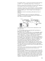
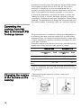
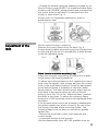
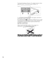
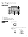
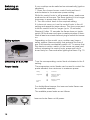
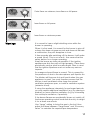
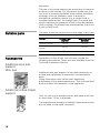
This cooktop is for use with Natural Gas and Universal LPG
PCT915B9TA
Robert Bosch Hausgeräte GmbH
Carl-Wery-Straße 34
81739 München
Cod. 9000714183 B
www.bosch-home.com
Content
Safety considerations . . . . . . . . . . . . . . . . 5
For your safety . . . . . . . . . . . . . . . . . . . . . . . 5
What to do if you smell gas . . . . . . . . . . . . . . 5
Warnings . . . . . . . . . . . . . . . . . . . . . . . . . . . 5
Installation . . . . . . . . . . . . . . . . . . . . . . . . . 7
Statutory requirements . . . . . . . . . . . . . . . . . . 7
Preparing to install . . . . . . . . . . . . . . . . . . . . . . . 7
Clearances . . . . . . . . . . . . . . . . . . . . . . . . . . . . . 8
Installation of cooktop into the kitchen bench . . 9
Connection . . . . . . . . . . . . . . . . . . . . . . . . . . . 10
Electrical . . . . . . . . . . . . . . . . . . . . . . . . . . 10
Gas . . . . . . . . . . . . . . . . . . . . . . . . . . . . . 10
Conversion from Nat. Gas to Universal LPG . . 12
To change injectors . . . . . . . . . . . . . . . . . . . . 12
Changing the nozzles of the burners on the
cooktop . . . . . . . . . . . . . . . . . . . . . . . . . . . . 12
Adjustment of the taps . . . . . . . . . . . . . . . . . 13
Operating instructions. . . . . . . . . . . . . . . . 15
Burner locations . . . . . . . . . . . . . .
The gas burners. Operation . . . . .
Switching on automatically . . . . .
Safety system . . . . . . . . . . . . . . .
Switching off a burner . . . . . . . . .
Power levels . . . . . . . . . . . . . . . .
Warnings. . . . . . . . . . . . . . . . . . .
Suitable pans . . . . . . . . . . . . . . . .
Accessories . . . . . . . . . . . . . . . . .
Additional wok pan support . . . .
Additional coffee maker support .
Cooking recommendation . . . . . .
Precautions for use. . . . . . . . . . . .
Cleaning and maintenance . . . . .
Cleaning . . . . . . . . . . . . . . . . .
Unsuitable products . . . . . . . . .
Maintenance . . . . . . . . . . . . . .
Service . . . . . . . . . . . . . . . . . . .
Wiring diagram . . . . . . . . . . . . . .
.
.
.
.
.
.
.
.
.
.
.
.
.
.
.
.
.
.
.
.
.
.
.
.
.
.
.
.
.
.
.
.
.
.
.
.
.
.
.
.
.
.
.
.
.
.
.
.
.
.
.
.
.
.
.
.
.
.
.
.
.
.
.
.
.
.
.
.
.
.
.
.
.
.
.
.
.
.
.
.
.
.
.
.
.
.
.
.
.
.
.
.
.
.
.
.
.
.
.
.
.
.
.
.
.
.
.
.
.
.
.
.
.
.
.
.
.
.
.
.
.
.
.
.
.
.
.
.
.
.
.
.
.
.
.
.
.
.
.
.
.
.
.
.
.
.
.
.
.
.
.
.
.
.
.
.
.
.
.
.
.
.
.
.
.
.
.
.
.
.
.
.
.
.
.
..........
15
15
16
16
16
16
17
18
18
18
18
19
20
21
21
21
21
22
23
3
Dear customer,
Congratulations on your choice and thank you for purchasing one of our appliances. This
practical, modern and functional appliance is manufactured using materials of the highest
quality which are subject to strict quality control checks throughout the entire manufacturing
process. The appliance is meticulously tested to ensure that it meets your demands and
produces perfect cooking results.
Do not remove the appliance from its protective packaging until it is installed in the unit.
Please read these instructions carefully before proceeding to install and use the appliance.
The information contained in these instructions is essential for the correct operation of the
appliance and, more importantly, for your safety.
The packaging of your appliance has been manufactured using only the materials which are
strictly necessary to guarantee efficient protection during transport.
These materials are 100% recyclable, thus reducing the environmental impact. You can also
contribute to caring for the environment, by following the advice below:
- dispose of the packaging in the appropriate recycling bin
- before you get rid of an old appliance, make sure you disable it. Contact your local authority
to find out the address of your nearest recycling centre to dispose of your appliance
- do not pour used oil down the sink. Collect it in a sealed container and take it to an
appropriate collection point or, failing that, place it in the rubbish bin (it will end up in a
controlled dump; this is probably not the best option, but it will avoid contaminating ground
water)
IMPORTANT:
In the unlikely event that the appliance should be damaged or not meet your expectations
in terms of quality, please inform us as soon as possible. For the warranty to be valid, the
appliance must not have been tampered with, or used inappropriately.
4
Safety considerations
For your safety
If the information in this manual is not followed exactly, a
fire or explosion may result causing property damage,
personal injury or death.
Do not store articles on or against this appliance.
Do not store flammable material near this appliance.
Do not spray aerosols in the vicinity of this appliance
while it is in operation.
What to do if you
smell gas
Do not try to light the appliance.
Do not touch any electrical switch; do not use any phone
in your building.
Inmediately call your gas supplier from a neighbour’s
phone. Follow the gas supplier’s instructions.
If you cannot reach your gas supplier, call the fire
department.
Installation and service must be performed by an
authorised person.
Warnings
DO NOT MODIFY THIS APPLIANCE.
Do not allow the flame to extend beyond the edge of the
cooking utensil. This instruction is based on safety
considerations.
Do not forget that the unit becomes hot when in use.
Common sense is important. Just because the flame is
out, does not mean parts cannot still be hot.
This appliance shall not be used for space heating. This
instruction is based on safety considerations.
Be sure to disconnect the electrical supply before
disassembly of the appliance.
Keep the appliance area clear and free from combustible
materials, gasoline and other flammable vapours and
liquids.
This appliance must be installed in a position with the
proper level of ventilation. Do not obstruct the flow of
combustion and ventilation air.
Cabinets installed above the gas cooktop must have a
minimum clearance of 650 mm (24”).
The gas pressure regulator supplied with the appliance
must be installed in line with the gas pipe. (N.G. only).
For pressure testing in excess of 3.5 kPa (1/2 psig) the
appliance and its individual shutoff valve must be
disconnected from the gas supply piping system.
5
Important. When using a very large pot, leave a gap of at
least 60 mm (2”) to avoid damaging any parts in bench
top wood, plastic or other non-heat resistant materials.
Never leave oil or hot fat unattended.
The surfaces on heating and cooking appliances get hot
when in use. Be careful. Keep children away from the
appliance.
Only use your appliance for the preparation of food and
never for room-heating purposes.
This appliance leaves the factory set for the gas supply
indicated on the data label. Call the Service Centre if it
needs to be altered.
Do not tamper inside the appliance. If necessary, call
your local Service Centre.
Overheated fat or oil can easily catch fire. Never leave the
appliance unattended when cooking food with fat or oil,
e.g. chips.
Never pour water on burning fat or oil. DANGER OF
BURNS! Cover the receptacle to smother the flames and
turn the cooktop off.
In the event of a fault, cut the gas and electricity supplies
to the appliance. Call our Service Centre to repair the
fault.
Do not use unstable or uneven-based receptacles on
cooking plates or burners. They may accidentally tip over.
If a gas supply knob/valve jams, do not force it. Call your
official Service Centre immediately for them to repair or
replace it.
The illustrations used in this booklet are only intended as
a guide.
Grids become very hot during use. When operating the
appliance control knobs, take care not to make contact
with the grids.
Do not use this appliance neither in marine craft nor in
caravans.
This appliance is not intended for use by persons
(including children) with reduced physical, sensory or
mental capabilities, or lack of experience and knowledge,
unless they have been given supervision or instruction
concerning use of the appliance by a person responsible
for their safety.
Make sure you keep these instructions for use and
assembly in a safe place, so that you can hand them on
with the appliance if it ever changes owner.
Note: To avoid jeopardising the electrical safety of the
appliance, it is forbidden to use high-pressure or steam
jet cleaning devices.
SHOULD THE RELEVANT CONDITIONS NOT BE
PROPERLY SATISFIED, THE INSTALLER, AND NOT THE
MANUFACTURER, SHALL HELD LIABLE.
6
Installation
Statutory
requirements
This installation must conform with the following:
Ø Manufacturer’s Installation instructions
Ø Local Gas Fitting Regulations
Ø Municipal Building Codes,
Ø Refer to AS/NZS 5601.1 for Gas Installations.
Ø S.A.A. Wiring Code
Ø Local Electrical Regulations
Ø Any other statutory regulations
Preparing to install
Refer to AS/NZS 5601.1 for piping size details. These
built-in cooktops are intended to be inserted in a
benchtop cutout.
Only an officially authorised technician should connect
the appliance.
Before you begin, turn off the gas and electricity supply.
Installation dimensions are shown in Fig.1.
Fig. 1
7
Before connecting the unit, check whether the local
connection conditions (type of gas) are compatible with
the unit’s setting. Observe any special conditions
imposed by local suppliers (utilities). The specifications
of this cooktop are stated on the data label located on the
bottom of the cooktop base.
A duplicate data label is supplied for adhesion to an
accessible location near the hotplate if the data label on
the base of the hotplate cannot be accessed when the
hotplate is installed.
Clearances
A range hood fitted above the top must be installed
according to the installation instructions for the range
hood. A minimum distance of 650 mm is required for a
range hood and 750 mm for an exhaust fan.
Any adjoining wall surface situated within 200 mm from
the edge of any hob burner must be a suitable noncombustible material for a height of 150 mm for the
entire length of the hob. Any combustible construction
above the hotplate must be at least 650 mm above the
top of the burner and no construction shall be within
450 mm above the top of the burner.
A minimum depth of 60 mm from the top of the worktop
surface must be provided for the appliance.
If the base of the hotplate can be touched, a protecting
shield must be fitted. This shield must be at least 10 mm
from the lowest part of the hotplate and must be capable
of withstanding the appliance temperatures. Minimum
thickness of benchtop is 30 mm. See Fig. 2.
Ø The shield material must be mdf or similar with
minimum thickness of 12 mm.
Ø The shield overall dimensions must be 850 mm wide x
480 mm deep.
Ø Provide cut-out in right hand rear of shield of 80 mm
wide x 80 mm deep to provide for gas regulator / LP
connection fitting.
8
After installation of the shield the clearance around the
top and sides of shield will allow adequate ventilation.
Ensure the side and top clearances are not obstructed.
Fig. 2
If an oven is positioned below the cooktop the barrier
does not need to be fitted, but a space of 35 mm must
be maintained between the underside of the cooktop and
the top of the oven.
A space of 5 mm must be maintained between the
benchtop and the top front part of the oven. See Fig. 2.
Installation of cooktop
into the kitchen bench
Installation procedure:
Side clearances: If the distance measured from the
periphery of the nearest burner to any vertical surface is
less than 200 mm, the surface shall be protected in
accordance with clauses 6.10.1.2 of AS/NZS 5601.1
1. For cutout dimensions and clearances refer Fig.1.
2. The clips and the adhesive seal (underside of the
cooktop), Fig. 3, are already fitted (depending on the
model), do not under any circumstances remove them.
The seal ensures that the entire work surface will be
watertight, and prevents water seepage. In order to fit the
appliance into the kitchen unit, first place the cooktop in
the correct position then loosen each of the clips so that
they all turn freely (it is not necessary to completely undo
them).
Insert and centre the cooktop.
Press the sides of the cooktop until it is supported around
its entire perimeter.
Turn the clips and tighten them fully. Fig. 3.
9
Fig. 3.
Connection
Electrical
Fig. 4
An electrical 10 amp socket needs to be within 1 m of the
hotplate to allow electrical connection. The socket must
remain accessible after installation of the appliance.
Important note:
This appliance is connected to the mains (240 VAC) by
means of the connecting lead which must be fixed to the
kitchen unit to prevent it from coming into contact with hot
parts of the cooktop (or an oven installed underneath)
and remain accessible after installation of the cooktop.
When making this connection make sure that the lead
cannot come into contact with hot parts of the cooktop.
Important: This appliance must be earthed. When
connecting the cooktop ensure that the earth wire is
connected first and that all wires are connected to the
correct terminals. Fig. 4.
Gas
During the planning stage, consider the position of supply
connections.
The cooktop must be connected to the gas supply with
upstream connection of an isolation valve in accordance
with the respectively valid regulations. We recommend
that the isolation valve be fitted prior to the cooktop to
enable isolation of cooktop from gas supply. The valve
must be easily accessible at all times.
To find out the factory set gas type, see bottom of
cooktop next to gas connection.
Remove plastic cap from gas supply line prior to installation.
10
Fit regulator (N.G.) or a test point (Universal LPG) directly
to the R 1/2’’ connection as per Fig. 5. and Fig. 6.
Direction of gas flow is indicated on the rear of the regulator.
For position of the inlet connection refer Fig.1.
Use pipe compound or thread sealant, properly theaded
pipes and careful assembly procedure so that there is no
cross threading, etc., which might cause damage or
leakage.
Make sure that all connections peformed are free of
leakage.
The manufacturer does not accept any liability for
leakage on connections performed by the installer or if
the L-tube is moved or twisted.
Fig. 5
Fig. 6
There are two ways to carry out the connection to the
main gas line:
A. The hotplate can be connected with rigid pipe as
specified in AS/NZS 5601.1
B. Flexible Hose: If installing with a hose assembly, install
with a hose assembly that complies with AS/NZS 1869
(AGA Approved), 10 mm ID, class Bor D, no more than
1,2 m long and in accordance with AS/NZS 5601.1.
Ensure that the hose does not contact the hot surfaces of
the hotplate, oven, dishwasher or any other appliance that
may be installed underneath or next to the hotplate. The
hose should not be subjected to abrasion, kinking or
permanent deformation and should be able to be
inspected along its entire length with the cooktop in the
installed position. Unions compatible with the hose fittings
must be used and all connections tested for gas leaks.
The supply connection point shall be accessible with the
appliance installed.
WARNING: Ensure that the hose assembly is restrained
from accidental contact with the flue outlet of an
underbench oven.
Before Leaving- Check all connections for gas leaks with
soap and water. DO NOT use a naked flame for detecting
leaks. Ignite all burners both individually and concurrently
to ensure correct operation of gas valves, burners and
ignition. Turn gas taps to low flame position and observe
stability of the flame for each burner individually and all
together. Adhere the duplicate data plate to an
11
accessible location near the hotplate. When satisfied with
the hotplate, please instruct the user on the correct
method of operation. In case the appliance fails to
operate correctly after all checks have been carried out,
refer to the authorised service provider in your area.
It should be expressly noted that we cannot accept any
liability for direct or indirect damage caused by wrong
connection, leakage or improper installation. When being
repaired, the appliance must always be disconnected from
the mains supply; if required, notify our customer service.
Converting the
cooktop from Nat.
Gas to Universal LPG
To change injectors
All work involved in installation, setting and adaptation to
a different gas type must be carried out by authorised
personnel from our Service Centre and must comply with
current regulations and the conditions laid down by the
local gas company.
Request change-over injectors from our customer service
deparment (refer injector chart below for sizes).
Natural Gas
Burner
Universal LPG
Hourly Gas Injector Hourly Gas Injector
Consumption
mark Consumption mark
(MJ)
(MJ)
Auxiliary
3,60
90
3,50
50
Semi-rapid
6,50
118
6,00
67
Dual double
flame
-
85/140
-
46/71
Before conversion the cooktop must be disconnected
from the electricity and gas valves must be turned to the
OFF position.
Changing the nozzles
of the burners on the
cooktop
12
- Remove the pan supports, burner covers and
diffusers.Fig. 7.
Fig. 7
- Change the nozzles using the spanner provided by our
Service Centre (code 340847, for double and triple flame
burners code 340808), taking special care to ensure that
the nozzle does not fall when it is removed from the
burner or when fitted. Fig. 8.
Ensure that it is completely tightened in order to
guarantee the seal.
Fig. 8
Adjustment of the
taps
Set the control knobs to minimum.
Remove the control knobs from the taps. Fig. 9.
It has a flexible rubber valve reinforcing ring. Simply press
on this seal with the tip of a screwdriver to allow access
to the tap adjusting screw.
Fig. 9
Never remove the valve reinforcing ring.
Adjust the minimum ring setting by turning the by-pass
screw using a flat head screwdriver.
To adjust the minimum flame for N.G. replace the control
knob onto the spindle, light the gas and turn the control
knob to the small flame position. Screw the adjustment
screw anti-clockwise to estabilish a minimum stable
flame position. The flame should remain alight and not
burn back to the injector when the valve is turned
quickcly from ‘Full On’ to the “Minimum flame” position
and back a few times. To adjust the minimum flame
position for ULPG the screw must be fully tightened down
clockwise.
If the by-pass screw cannot be accessed, disassemble
the grease splash tray, which is fixed to the rest of the
hob using a clip and screw mounting system. The
following steps must be taken to remove the grease
splash tray:
- Remove all the burner covers, pan supports and
control knobs.
- Loosen the screws on the burners.
Use the disassembly lever 483196 available from our
13
Technical Assistance Service. To release the front clips,
apply the lever to the area shown in figure 10.
Fig. 10
To assemble the grease splash tray again, proceed in
the reverse order to removal.
It is important that all the seals are refitted to form a seal.
These devices are essential for the correct operation of
the appliance as they prevent liquids and dirt from
entering the appliance.
Refit the control knobs.
Never remove the tap spindle. In the event of a
malfunction, change the whole tap.Fig. 11.
Fig. 11
Warning! After finishing, the sticker indicating the new type
of gas must be placed close to the specifications plate.
14
Operating instructions
Burner locations
1
2
3
4
5
Pan supports
Control knobs
Auxiliary burner (up to 1 kW)
Semi-rapid burner (up to 1,75 kW)
Dual double-flame burner (up to 5 kW)
The gas burners
Operation
There are indications to show which burner each control
knob operates. Fig. 12.
Fig. 12
It is essential to ensure that all the burner parts and pan
supports are correctly installed for the appliance to work
correctly. Fig.13-14.
Fig. 13
Fig. 14
15
Switching on
automatically
If your cooktop can be switched on automatically (ignition
sparkers):
1. Press the chosen burner control knob and turn it
anticlockwise to the maximum power setting.
While the control knob is still pressed down, sparks are
produced on all burners. The flame ignites (it is no longer
necessary to press down the control knob).
2. Turn the control knob to the required setting.
If it does not come on, turn the control knob to the off
setting and repeat the steps above. This time, press and
hold the control knob for longer (up to 10 seconds).
Warning! If after 15 seconds the flame does not ignite,
switch off the burner and open a nearby window or door.
Wait at least one minute before trying to switch the burner
on.
Safety system
Fig. 15
Ignition
sparker
Depending on the model, your cooktop may have a
safety system (thermocouple) that prevents the flow of
gas if the burners accidentally switch off. To ensure that
this device is active, switch on the burner as usual and,
without releasing the control knob, press and hold it
down firmly for 4 seconds after lighting the flame. Fig. 15.
Thermocouple
Switching off a burner
Turn the corresponding control knob clockwise to the 0
setting.
Power levels
The progressive control knobs can be used to control the
power needed, from minimum to maximum power.
Setting
Large flame
Economy
flame
$
—
˜
Control off
Maximum capacity
or aperture and
electricity on
Minimum capacity
or aperture
For double-flame burners, the inner and outer flames can
be controlled separately.
The available power levels are as follows:
Inner and outer flame on full power.
16
Outer flame on minimum, inner flame on full power.
Inner flame on full power.
Inner flame on minimum power.
Warnings
It is normal to hear a slight whistling noise while the
burner is operating.
When it is first used, it is normal for the burner to give off
odours; this does not pose any risk and does not indicate
a malfunction; they will disappear in time.
A few seconds after switching off the burner, it will make
a sound (thud). This is not a fault - this means that the
safety device is no longer operating.
Keep the burner as clean as possible. If the ignition
sparkers are dirty they will not light properly. Clean them
periodically using a small non-wire brush. Bear in mind
that the ignition sparkers must not suffer any serious
impacts.
An orange-coloured flame is normal. This is caused by
the presence of dust in the atmosphere, spilt liquids, etc.
The kitchen will become hot and humid when this gas
appliance is used. You must therefore ensure that the
kitchen is well ventilated: either keep the natural
ventilation apertures open, or install a ventilation system
(extractor hood).
If using the appliance intensively for prolonged periods,
you may require additional ventilation (e.g. by opening a
window) or more effective ventilation (e.g. by increasing
the cooktop's ventilation, if possible).
If the burner flames are accidentally blown out, switch off
the burner operating control knob and do not try to relight
it for at least one minute.
Use “Large” setting to bring the pan to the boil, then
adjust the flame between “Large flame” and “Economy
flame” to maintain the required pan temperature.
17
Important:
The use of a cooktop leads to the production of heat and
moisture in the kitchen. For this reason make sure that
the room is properly ventilated. Keep natural ventilation
openings, such as windows, open or provide a
mechanical ventilation device (e.g. a range hood or
overhead exhaust fan). An orangy flame is normal and
simply indicates the presence of salt in the atmosphere
(from cooking). If the flame has yellow patches, this is not
a fault (of any kind).
Suitable pans
The pans should not exceed the cooker edge in any case.
The chart below gives the correct pan usage for each burner
Burner
Accessories
Minimum pan
diameter
Maximum pan
diameter
Auxiliary burner
12 cm
16 cm
Semi-rapid
burner
14 cm
20 cm
Wok burner
22 cm
Depending on the model, the hob may include the
following accessories. These are also available from the
Technical Assistance Service.
Additional wok pan
support
Wok pan
Additional wok pan support: to be used exclusively on
double and triple-flame burners with concave-based
pans.
Using these pans may cause some temporary
deformation of the grease splash tray. This is normal and
does not affect the operation of the appliance.
Additional coffee maker
support
Only for use on the auxiliary burner with pans which are
no more than 12 cm in diameter.
The manufacturer accepts no liability if these accessories
are not used or are used incorrectly.
18
Cooking
recommendation
Very high, high
Medium
Low
Auxiliary burner
Casseroles, rice
pudding and
caramels.
Defrosting and
slow cooking:
vegetables, fruits
and frozen
products.
Melting:
butter, chocolate
and jelly.
Semi-rapid burner
Steaming potatoes, Reheating, keeping things hot and
fresh vegetables,
making tasty casseroles.
stews, pasta.
Wok burner
Boiling, grilling,
browning and
Asian food (wok).
Reheating and keeping things hot:
cooked and pre-cooked dishes.
Do not place anything, eg. flame tamer,
asbestos mat, between pan and pan support as
serious damage to the appliance may result.
Do not remove the pan support and enclose the
burner with a wok stand as this will concentrate
and deflect heat onto the hotplate.
Do not use large pots or heavy weights which
can bend the pan support or deflect flame onto
the hotplate.
19
Precautions for use
The following advice is intended to help you save energy
and prevent pan damage:
Use pans which are the right size for each burner.
Do not use small pans on large burners. The flame
should not touch the sides of the pan.
Do not use damaged pans, which do not sit evenly on
the cooktop. Pans may tip over.
Only use pans with a thick, flat base.
Do not cook without using a lid and make sure the lid is
properly fitted to avoid wasting energy.
Always place the pan right over the burner, not to one
side. Otherwise it could tip over.
Do not place large pans on the burners near the control
knobs. These may be damaged by the very high
temperatures.
Place the pans on the pan supports, never directly on
the burner.
Pans should be placed on the cooktop carefully.
Do not strike the cooktop and do not place excessive
weight on it.
Make sure that the pan supports and burner covers are
correctly positioned before using the appliance.
20
Cleaning and
maintenance
Cleaning
Once the appliance is cool, use a sponge to clean it with
soap and water.
After each use, clean the surface of the respective burner
parts once they have cooled down. If any residue is left
(baked-on food, drops of grease etc.), however little, it will
become stuck to the surface and more difficult to remove
later. The holes and grooves must be clean for the flame
to ignite properly.
The movement of some pans may leave metal residue on
the pan supports.
Clean the burners and pan supports using soapy water
and scrub with a non-wire brush.
If the pan supports are fitted with rubber rests, ensure that
these are also cleaned. The rests may come loose and
the pan support may scratch the hob.
Always dry the burners and pan supports completely.
Water droplets or damp patches on the hob at the start
of cooking may damage the enamel.
After cleaning and drying the burners, make sure the
burner covers are correctly placed on the diffuser.
Unsuitable products
Do not use steam cleaners. This could damage the hob.
If your hob is fitted with a glass or aluminium panel, never
use a knife, scraper or similar to clean the point where it
joins the metal.
Maintenance
Always clean off any liquid as soon as it is spilt: you will
save yourself any unnecessary effort.
Do not leave acidic liquids (e.g. lemon juice, vinegar, etc.)
on the hob.
Where possible, do not allow salt to come into contact
with the surface of the electric hob.
The ring cover of the double or triple flame burner and
stainless steel parts such as hotplate rings, top sheet and
the area around the burners may become discoloured
over time. This is normal because of the high
temperatures. Each time the appliance is used these
parts should be cleaned with a product that is suitable for
stainless steel.
The stainless steel cleaner must not be used in the area
around the controls. The (printed) symbols may be wiped
off.
21
Service
DO NOT MODIFY THIS APPLIANCE.
Only authorized personnel from the Service Centre are
qualified to work on the appliance.
Sometimes certain faults detected can be easily resolved.
Before calling the Service Centre, bear in mind the
following advice:
Fault
Possible cause
Solution
The general electrical
system is
malfunctioning.
Defective fuse.
Check the fuse in the main fuse
box and change it if it is damaged.
Check the main control panel to
see if the automatic safety switch
or circuit breaker has tripped.
The automatic on
function does not work.
There may be food or cleaning
products stuck between the
ignition sparkers and the burners.
The burners are wet.
The automatic safety switch or
circuit breaker has tripped.
The burner covers are not
correctly positioned.
The appliance is not earthed, is
not correctly connected or the
earth wire is faulty.
The space between the ignition
sparker and the burner must be
clean.
Dry the burner covers carefully.
Check that the covers are correctly
positioned.
Contact the electrical installer.
The burner flame is not
uniform.
The burner components are not
correctly positioned.
The grooves on the burner are
dirty.
Ensure the components are
correctly positioned.
The flow of gas does
not appear normal or
no gas comes out.
The gas supply is blocked via
intermediary valves.
If the gas is supplied from a gas
cylinder, check that this is not
empty.
Open all intermediary valves.
Change the gas cylinder.
The kitchen smells of
gas.
A gas tap has been left on. There
may be a leak in the gas cylinder
coupling.
Possible gas leak.
Turn off the gas taps.
Check that the coupling is sound.
The control knob was not held
down for long enough.
Once the burner is lit, hold the
control knob down a few seconds
longer. Clean the grooves on the
diffuser.
The safety valves on
one of the burners are
not working.
The grooves on the diffuser are
dirty.
Clean the grooves on the diffuser.
Shut off the gas supply, ventilate
the premises and immediately
notify an authorised installation
technician so that they can check
and certify the installation. Do not
use the appliance until you are
sure that there is no gas leak in the
installation or appliance itself.
Any of the following are considered to be abnormal
operation and may require servicing:
Yellow tipping of the cooktop burner flame.
Sooting up of cooking utensils.
Burners not lighting properly.
Gas valves, which are difficult to turn in case the
appliance fails to operate correctly, contact the
authorised service provider in your area.
22
Wiring diagram
A. Switch
B. Blue wire
C. Brown wire
D. Terminal
E. Ignition module
www.bosch-home.com
CIF: A-28-893550
ROBERT BOSCH HAUSGERÄTE GMBH
!:P
CT915B9TA
&
'(
!
ULPG
12
01
Test point pressure (kPa)
Injectors marks
LHF
46/71
85/140
50
90
LHR
46/71
RHF
85/140
67
RHR
118
50
90
RHF
67
RHR
118
55,00
56,20
,56.
In compliance with AS/NZS 3100 and AS 4551:2008
"*+
779!
220-240V, 0.8A, 50Hz
MADE IN SPAIN
Distributed by BSH Home Appliances Pty Ltd
GMK 10047
23