1
M252A
INTELLIGENT DOT IMPACT PRINTER
Operation manual
Rev. 1.02
BE SURE TO READ BEFORE USE.
Introduction
Thank you for purchasing our intelligent printer M252A.
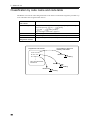
This product is to be used by connecting it to our loadcell indicators or digital indicators through the
SI/F (two-wire serial interface). External equipment data other than our indicators can also be
printed by adding optional BCD input or RS-232C interface.
Read this manual and understand the descriptions carefully before use.
After reading the manual, always keep it handy so that it can be referred to at any time.
2010/10/01
I
SAFETY PRECAUTIONS
Be sure to read for safety.
In order to have an M252A Intelligent Printer used safely, notes I would like you to surely
follow divide into
WARNING
and
CAUTION
, and are indicated by the following
documents. Notes indicated here are the serious contents related safely. Please use after
understanding the contents well.
WARNING
Misuse may cause the risk of death or
serious injury to persons.
CAUTION
Misuse may cause the risk of injury to
persons or damage to property.
II
WARNING
Warning on design
● For the entire system to function safely when the M252A becomes faulty or
malfunctions, provide a safety circuit outside the M252A.
Warning on installation
● Do not modify the M252A. Doing so may cause fire or electric shocks.
● Do not install in the following environments.
- Places containing corrosive gas or flammable gas.
- Where the product may be splashed with water, oil or chemicals.
Warning on wiring
● Do not connect a commercial power source directly to the signal input/output
terminals.
● Be sure to use crimp contacts for connection to terminal blocks, and never connect
bare wires.
● Be sure to ground the protective ground terminal.
● Before performing the following, make sure that no power is applied.
- Attachment/detachment of connectors of options, etc.
- Wiring/connection of cables to the signal input/output terminals.
- Connection to the ground terminal.
● For connection to the signal input/output terminals, check the signal names and pin
assignment numbers, and then carry out wiring properly.
● Before applying power, carefully check the wiring, etc.
Warning on wiring
● Use at a proper power supply voltage.
● Do not damage the power cord. Doing so may cause fire or electric shocks.
● Do not touch any signal input/output terminal while applying power. Doing so may
cause electric shocks or malfunctions.
● In the case of smoke, an abnormal smell or strange sound, immediately turn off the
power, and disconnect the power cable.
● About the built-in lithium battery
Never disassemble, deform under pressure or throw the battery
into fire.The battery may explode, catch fire or leak.
- Battery
Model : CR14250SE made by SANYO Electric Co., Ltd.
Nominal voltage : 3V
Nominal electric capacity : 850mAh
III
CAUTION
Caution on installation
● Do not install in the following environments.
- Locations exposed to direct sunlight.
- Where the temperature/humidity exceeds the range of the specifications.
- Places containing large quantities of salt or iron powder.
- Where the main body is directly affected by vibrations or shocks.
● Take adequate shielding measures when using at the following locations.
- Near a power line.
- Where a strong electric field or magnetic field is formed.
- Where static electricity, relay noise or the like is generated.
Caution on wiring
● For sensors, external inputs/outputs and options, use shielded cables.
Caution during startup and maintenance
● For turning on/off the power, be sure to keep intervals of 5 seconds or more.
Caution during use
● Do not open the front cover with the power on when replacing the ribbon cassette, etc.
The printer may start sudden movement, and you may injure yourself.
● Do not drop foreign objects such as screws inside the printer. If an object is dropped,
immediately turn off the power, and completely remove the foreign object before using
the printer.
● Do not touch the print head immediately after printing because the print head is hot.
● Never print without paper or a ribbon cassette. Also, do not print out of the paper width.
● Be sure to use a specified ribbon cassette. Use of an unspecified one will cause a
failure.
● After replacing the ribbon cassette, check that the ink ribbon is not slack. If slack, turn
the knob in the direction of the arrow to remove the slack before operation.
● Use paper appropriate to the specifications.
Caution during disposal
● If you dispose of the product, handle it as industrial waste.
IV
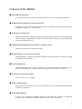
Features of the M252A
■ Dot impact mechanism
A 24-digit dot impact type printer mechanism that allows use of copying paper is loaded.
■ Sophisticated statistical computing functions
In addition to grand totals and sub totals, maximum, minimum, average, standard deviation,
histograms, diagrams, etc., can be printed.
■ Economical double print
Thanks to the double printing function by which data from two indicators can be printed and
added, statistical computations of a double measuring machine having two measuring heads
can be performed by one unit.
■ Histograms and diagrams convenient for quality control
Variations in data can be understood visually.
■ Simple setting in an interactive manner
Setting operation is simple in an interactive manner that requires input of set values according
to guidance from the M252A.
■ Code classification
Print data assigned codes (within 6 characters for numerical values and katakana) can be
classified and added on a code-by-code basis (32 types at the maximum of each ch).
■ Convenient free power supply
100V to 240V AC is acceptable.
■ Perfect data backup
All set values and other data are stored in a nonvolatile memory and lithium-battery-backedup memory, respectively.
■ Selectable interface
A 2-ch SI/F is equipped as standard. BCD input and RS-232C interface are optionally
available. (Only 1ch of either a BCD or RS-232C option can be connected.)
V
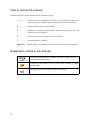
How to review this manual
Manual contents are roughly divided into the following six parts.
1 - 3 ..............Safety instructions, installation of the printer, test printing and connections
with indicators are explained. Basic use of the printer can be understood.
4 .......................Settings for the printer use are explained.
5 .......................Methods for connecting optional BCD input and RS-232C interface, and
method for use are explained.
6 .......................Functions for greater use of the printer are explained.
7 .......................Troubleshooting is explained.
Appendix .......Specifications, consumables, after-sales service of this printer are explained.
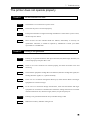
Explanatory marks in this manual
Note
Precautions and restrictions to operate the printer properly. Be sure to
read to prevent misoperation.
Convenience and reference for use of the printer. Reading is highly
recommended.
Operating procedures for printer settings are explained.
VI
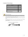
Contents of the package
Item name
Quantity
M252A printer body
1
Roll paper
1
Ribbon cassette (One is already installed.)
2
AC cable
1
Instruction manual (this book)
1
Mini screwdriver
1
Roll paper installing bar
1
Control signal input connector 57-30500 DDK
(attached with BCD input OP)
1
About the power cable
・The power cable attached to this product as standard equipment can be used in the AC100V
power supply in Japan. (Official ratings voltage AC125V)
Please use the power cable authorized in the country when you use this product outside
Japan.
・Our company sells following resistance pressure cable AC250V (European standard
product) separately.
Please purchase it from us when you need after confirming its plug shape/voltage.
CAAC3P-CEE7/7-B2 : CEE7/7 Plug cable (2m)
VII
CONTENTS
1. Before turning on the power .....................1
Name and function of each part ............................... 2
[Front panel] .......................................................... 2
[Rear panel] ........................................................... 3
Front panel key .............................................. 4
2. Printer preparations ............................7
Installing a ribbon cassette ................................. 8
Installing the power cord ................................... 10
AC spec. .............................................................. 10
DC spec. (Depending on the request at the time of order) .............. 10
Installing roll paper ....................................... 11
3. Connecting with indicators .....................13
SI/F (two-wire serial interface) ............................ 14
About the SI/F ........................................................ 14
About the SI/F of the M252A ........................................... 14
Connecting through the SI/F ................................. 15
Try to print ................................................ 16
About input ch's ............................................ 16
Print data input ch's and alarm sound ....................... 17
In the case of single print ........................................... 17
In the case of double print ........................................... 17
What is printed without valid data at Print-Every time ................ 17
4. For greater use of the printer .................19
Basics of settings .......................................... 20
Mode configuration of the M252A ....................................... 20
Setting method of the M252A ........................................... 20
Basic operation of settings ........................................... 21
Cautions in setting ................................................... 23
Details of each setting ..................................... 24
01: Date/Time ......................................................... 24
02,03: Print Data Selection Ach/Bch ................................... 25
04,05: Unit Selection Ach/Bch ......................................... 26
06: Print Every ON/OFF ................................................ 26
07: Print Every Format ................................................ 27
VIII
08: Automatic Print ON/OFF ............................................ 30
09: Interval Print ON/OFF ............................................. 30
10: Interval Seconds .................................................. 31
11: GT/ST Print Format ................................................ 32
12: Types of Sub Totals ............................................... 34
13,15: Histogram Target Value Ach/Bch ................................. 35
14,16: Histogram Range Ach/Bch ........................................ 35
17: Standard Deviation ................................................ 37
18: Data Adding ON/OFF ................................................ 38
19: PRINT Key ON/OFF .................................................. 38
20: Batch Total ON/OFF ................................................ 39
21: Feed Lines ........................................................ 40
22: Code Selection Method ............................................. 40
23: Number of Code Digits Designation ................................. 41
24,25: Code Table Registration Ach/Bch ................................ 41
5. Optional interface .............................41
BCD input (option) .......................................... 44
BCD input settings .......................................... 48
41: BCD Decimal Point Position ........................................ 48
42: BCD Data Logic .................................................... 48
43: BCD Minus Logic ................................................... 48
44: BCD Over Logic .................................................... 48
45: BCD Strobe Logic .................................................. 48
RS-232C interface(option) ................................... 49
RS-232C settings ............................................ 50
46: RS-232C Transmission Rate ......................................... 50
47: RS-232C Parity Bit ................................................ 50
48: RS-232C Data/Stop Bit ............................................. 50
49: RS-232C Terminator ................................................ 51
50: RS-232C Answer Mode ............................................... 51
Communications format ....................................... 52
DC power source ............................................. 54
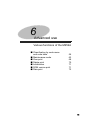
6. Advanced use ...................................55
Classification by code name and code table .................. 56
Code name registration performance with front panel keys .............. 57
Code table
- Difference from code names - ........................... 58
Code table registration performance ................................... 59
How to designate a code name/code table ............................... 61
IX
Maintenance mode ........................................... 63
1: Test Print ......................................................... 65
2: Sample Print ....................................................... 66
3: Self Test .......................................................... 66
4: Parameter List ..................................................... 67
5: Test Mode .......................................................... 67
Over print .................................................. 68
Over status (R) ....................................................... 68
Range over (U/L) ...................................................... 69
Delete print ................................................ 70
Initialization .............................................. 71
ROM version print ........................................... 71
Date print .................................................. 72
7. Troubleshooting ................................73
Classification of trouble ................................... 74
The printer does not operate properly ....................... 75
The printer does not function properly ...................... 77
Others ...................................................... 78
Appendix
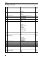
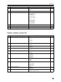
Setting mode list ........................................... 82
Option setting mode list .................................... 83
Maintenance mode list ....................................... 84
List of unit settings ....................................... 84
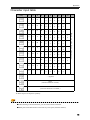
Character input table ....................................... 85
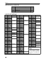
List of error messages ...................................... 86
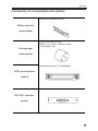
Introduction of consumables and options ..................... 87
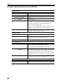
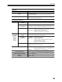
Product specifications of the M252A ......................... 88
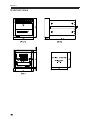
External views .............................................. 90
X
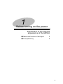
1
Before turning on the power
Explanation of the external
appearance of the M252A
■ Name and function of each part
■ Front panel key
2
4
1
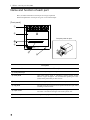
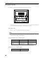
1. Before turning on the power
Name and function of each part
Here, the name and function of each part are simply explained.
Detailed explanations of each part are given in its related chapter.
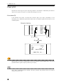
[Front panel]
①
②
The push panel is open.
③
④
⑤
⑥
Front parts
Name
Description
① Front panel keys
Press when operating and setting the M252A.
② Push panel
Open when setting paper or installing a ribbon cassette for the
M252A. It pops out approx. 3cm forward when pushing the center
(mark) of the panel until you hear it click.
③ Paper ejection slot
Printed roll paper is ejected from this slot with print on it.
④ Flip panel
The part below the push panel can be opened frontward. Open when
installing a ribbon cassette.
⑤ Paper cutter
Use when cutting roll paper ejected from the paper ejection slot.
The cutter is attached to the upper side of the ejection slot.
⑥ Power lamp
The green lamp lights when the power of the M252A is on.
2
1. Before turning on the power
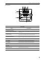
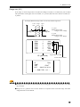
[Rear panel]
⑤ ⑦ ⑨
⑪
⑥ ⑧ ⑩
①
②
③
④
Rear parts
Name
Description
① Input terminal block
Connect various kinds of inputs.
② Power supply terminal block
Connect the power cord. Securely connect the power cord to a
power outlet.
③ Option space
Install an option to expand the functions of the M252A. Either BCD
input or RS-232C interface can be installed optionally.
④ Frame ground (F.G.)
Earth terminal.
Be sure to ground to prevent electrostatic interference, etc.
⑤ (1) COM
Common terminal of the external input terminal block.
⑥ (2) FEED
Feeds when short-circuited with the COM terminal.
⑦ (3) PRINT
Prints when short-circuited with the COM terminal.
⑧ (4) ST
Prints sub totals when short-circuited with the COM terminal.
⑨ (5) GT
Prints grand totals when short-circuited with the COM terminal.
⑩ (6) (7) SI/F Ach
Input terminal for the SI/F (Ach).
⑪ (8) (9) SI/F Bch
Input terminal for the SI/F (Bch).
3
1. Before turning on the power
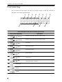
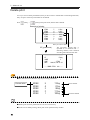
Front panel key
Key use differs with the modes, but basic use and the meaning of each key, and how to
designate it are simply explained below.
①
②
③
⑫
④
⑨
⑤
⑥
⑩
⑦
⑧
⑪
How to designate a key and its function (print mode)
Key (how to designate)
Description
Enters the code input (selection) mode of Ach.
①
(Code A)
②
(Code B)
③
(Date)
④
(Start)
⑤
(Stop)
⑥
(ST)
⑦
(GT)
Prints grand totals. The grand totals and printed counts are cleared,
and become 0.
⑧
(Del)
The last printed data is printed again, and is deleted from the target
of the grand totals (sub totals).
(Function)
⑩
(Print)
⑪
(Feed)
4
⑨
Enters the code input (selection) mode of Bch.
Prints date.
Starts interval print.
Stops interval print.
Prints sub totals.
Enters the setting mode.
Prints the current value.
Feeds paper by one line.
1. Before turning on the power
How to designate a key and its function (setting mode)
Key (how to designate)
⑥
(Hyphen)
⑦
(SP)
⑧
(No mark)
⑩
(Escape)
⑪
(Enter)
⑫
~
F
0
(Numerical keys)
Description
Inputs a hyphen.
Inputs a space.
Goes to the next input position.
Cancels an input value or set value.
Accepts an input value or set value.
Use for inputting numbers, alphabet and katakana.
For character input in code/code table registration, see "Code name registration performance with front
panel keys"(page 57), and "Code table registration performance"(page 59).
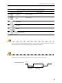
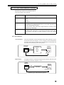
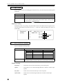
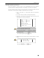
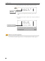
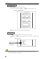
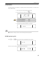
The following shows a timing diagram of the external input terminals on the panel.
PRINT/FEED/ST/GT
OFF
ON
MIN.30ms
MIN.60ms
5
1. Before turning on the power
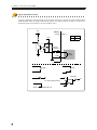
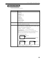
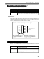
Input equivalent circuit
A signal is inputted to the signal input circuit by short-circuiting or opening the input terminal and the
COM terminal. Short-circuiting is effected by means of a contact (such as a relay or a switch) or a
noncontact (such as a transistor or an open-collector TTL).
Vcc
M252A
← inside outside →
Open OFF
Short ON
+5V
approx.
IC=6mA
COM
push
switch
1
toggle
*
IN
relay
transistor
IN
TTL open collector output
Short-circuited when IN is ‘H’
6
2
Printer preparations
Installing a ribbon cassette
and roll paper
■ Installing a ribbon cassette
■ Installing the power cord
■ Installing roll paper
8
10
11
7
2. Printer preparations
Installing a ribbon cassette
Use the PR350/10 (optional accessories) ribbon cassette.
Two ribbon cassette are attached (One ribbon cassette has already been installed at the time of delivery.) .
Note
■Do not open the front cover with the power on when
replacing the ribbon cassette, etc. The printer may start
sudden movement, and you may injure yourself.
■Do not drop foreign objects such as screws inside the
printer. If an object is dropped, immediately turn off the
power, and completely remove the foreign object before
using the printer.
■Do not touch the print head immediately after printing
because the print head is hot.
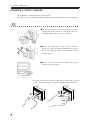
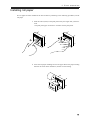
1. Push the center (mark) of the push panel with your finger until you hear it
click. The push panel pops out forward. And draw out the push panel.
8
2. Printer preparations
2. Open the flip panel downward. Catch the upper left of the installed ribbon
cassette with your finger(with your fingernail), and pull and remove it
frontward.
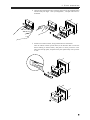
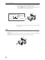
3. Install a new ribbon cassette, being careful about its orientation.
Turn the ribbon cassette upside down (in the direction that reverses the
PULL marking as shown below), and push it in until you hear it click.
Then close the flip panel, and push in the push panel firmly until you hear
it click.
9
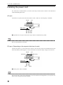
2. Printer preparations
Installing the power cord
For connection to terminal blocks, use cables with crimp contacts (M3) as shown in the illustration
without unbraiding their ends.
AC spec.
Connect the AC power cord. The input voltage is 100V - 240V AC. The frequency is 50/60Hz.
F.G.
AC IN
L
N F.G.
Within 6mm.
■ A parallel two-core power cable with crimp contacts is attached to the product.
Note
Be sure to ground the F.G. terminal.
DC spec. (Depending on the request at the time of order)
Connect the positive (+) side of the power source to the red screw side of the terminal block on the
back of the M252, and its negative (-) side to the black screw side.The input voltage is 12V-24V DC.
F.G.
DC IN
Red screw
Black screw
+ - F.G.
Within 6mm.
+
-
Red
Black
■ No DC power cable is included.
Note
Be aware that the voltage drops depending on the wire thickness and length.Also, never input an AC
power source. Doing so will cause a failure.
10
2. Printer preparations
Installing roll paper
No roll paper has been installed at the time of delivery. Referring to the following procedures, install
roll paper.
1. Push the center (mark) of the push panel with your finger until you hear it
click.
The push panel pops out forward. And draw out the push panel.
2. Insert the roll paper installing bar into roll paper. Direct the paper winding
direction as shown in the illustration, and set it to the bearing.
11
2. Printer preparations
3. Pass the end of the roll paper under the guide bar at the lower part of the
flip panel, and insert it between the guide bar and guide.
Press the
[FEED] key with the paper inserted, and release the key
when the paper comes out of the paper ejection slot.
Enlarged section
Roll paper
← Front
Guide bar
Guide
4. Remove the flexure of the roll paper, and push in the push panel firmly until
you hear it click.
Note
It may cause some trouble if you pull the paper fast or backward when the paper jam occurred during the
paper setting.
Please pull the paper in the direction of the arrow A slowly and straight to remove it after stopping the
paper feed.
Cut the power then on again when it doesn't return normally after removing the paper.
A
12
3
Connecting with indicators
■ SI/F (two-wire serial interface)
■ Connecting through the SI/F
■ Try to print
■ About input ch's
■ Print data input ch's and alarm sound
14
15
16
16
17
13
3. Connecting with indicators
SI/F (two-wire serial interface)
The M252A is equipped with a SI/F interface to connect it with UNIPULSE-manufactured digital
indicators or load cell indicators as standard. In this chapter, connection with indicators through the SI/
F is explained.
About the SI/F
The UNIPULSE's original SI/F is an interface to connect our F series indicators and printer, or
peripheral equipment, such as an external display. SI/F-compatible products can simply be connected
and used without a wareness of data content and the hardware specifications.
Specifications of the SI/F
Connection
Two-wire, nonpolar
Transmission
distance
Parallel two-core cable: 30m
Shielded cable: 300m
Transmission
data
Measuring/metering data, status information (result of comparison, MD,
zero alarm, etc.), error information, automatic print command, etc.
Signal standards
Signal level
Photocoupler-isolated current signal
Transmission
system
Start/stop synchronous system
Transmission
speed
600bps
Data bit
8bit
Start bit
1bit
Stop bit
1bit
Parity
ODD
About the SI/F of the M252A
The M252A is equipped with a 2-ch SI/F (Ach and Bch). 6-7PIN and 8-9PIN on the rear terminal block
correspond to Ach and Bch, respectively.
14
3. Connecting with indicators
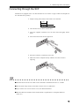
Connecting through the SI/F
The M252A is equipped with a 2-ch SI/F. Parallel two-core cables or captyre cables are adequate for
use. The SI/F has no polarity.
1. Strip the casing 0.2in (6mm) on the cable to be connected.
0.2in
2. Twist the bare wire to fit the terminal hole.
3. Insert the supplied screwdriver into the lower hole and lightly hold it
down.
4. Insert the twisted wires into the upper hole.
5. Pull the screwdriver out from the lower hole.
6. Make sure cable is clamped securely and does not come out with a
slight tug.
Note
■ Sectional area of electric wires that can be connected to terminal blocks are 0.2 - 2.5mm2.
■ Do not attach crimp contacts to the ends of electric wires or solder them.
■ If you connect two or more electric wires, twist them beforehand.
■ Be aware that the orientation of the terminal block is upside-down to our digital indicators
(F366, etc.)
15
3. Connecting with indicators
Try to print
The M252A prints when any of the following conditions are met.
1. When the
[PRINT] key is pressed. (*)
2. When No. 3 (PRINT) and No. 1 (COM) on the terminal block are short-circuited. (*)
3. When an automatic print command is sent from the SI/F.
4. When a print command is input to the RS-232C.
5. At intervals set for interval print. (*)
* In the cases of 1, 2 and 5, the M252A does not print if no print data is input.
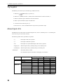
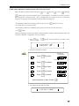
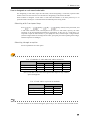
About input ch's
The M252A has two data input ch's. When using both ch's, select “8. Double print” or “9. Double print
with count” for [07: Print Every Format].
The following table shows input data to be printed.
・①
: Data input to SIF Ach is printed.
・②
: Data input to SIF Bch is printed.
・OP
: Data input to an option (BCD input or RS-232C) is printed.
・Single print : When the [Print Every Format] setting is not “Double print”.
・Double print : When the [Print Every Format] setting is “Double print”.
・Shaded part
: The alarm (buzzer) sounds.
See "Print data input ch's and alarm sound"(page 17) for details.
Input data
Without OP
With OP
16
SIF Ach
SIF Bch
SIF Ach + Bch
SIF Ach
SIF Bch
SIF Ach + Bch
SIF Ach + OP
SIF Bch + OP
SIF Ach + Bch + OP
OP
Single print
Ach
Bch
①
×
①
①
×
①
①
OP
①
OP
×
×
×
×
×
×
×
×
×
×
Double print
Ach
Bch
①
×
①
①
×
①
①
OP
①
OP
×
②
②
×
②
②
×
②
②
×
3. Connecting with indicators
Print data input ch's and alarm sound
In the case of single print
In the case where the input ch setting is single print (the [Print Every Format] setting is not double
print), if printing is attempted without print data input from Ach or an optional interface, the alarm
(buzzer) will sound, resulting in error printing.
In the case of double print
In the case where the input ch setting is double printing (the [Print Every Format] setting is double
print), if printing is attempted without print data input from both SIF Ach and an optional interface, and
without print data input from SIF Bch, the alarm (buzzer) will sound, resulting in error printing.
However, printing of the input ch('s) will be produced.
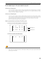
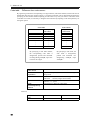
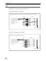
What is printed without valid data at Print-Every time
In the case of no Ach data (single print / double print)
Ach
SIF
Data
NG
Ach
SIF,BCD
Data
NG
With BCD OP
Ach
SIF,RS
Data
NG
With RS-232C
In the case of no Bch data (double print)
Bch
SIF
Data
NG
Option input can be made only with Ach. If data input is made by both of option input and SI/F input,
priority is given to the SI/F.
17
3. Connecting with indicators
M E M O
18
4
For greater use of the printer
Explanation of each setting
■ Basics of settings
■ Details of each setting
20
24
19
4. For greater use of the printer
Basics of settings
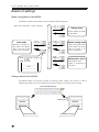
Mode configuration of the M252A
The M252A consists of four modes. See the "Setting mode list"(page 80).
When A key is pushed, “Quit" is printed.
+
Setting mode
Printer settings are made
in this mode.
F
0
+
Printing is produced in
this mode. The M252A
starts with this mode
after power is turned on.
When
Select
Print mode
Option setting mode
+
Option settings are made
in this mode. You cannot
enter this mode if no
option is equipped.
+
key is pushed,
Maintenance mode
“Quit” is printed.
Maintenance of the
printer is performed in
this mode.
---------------Quit
----------------
Setting method of the M252A
The M252A adopts an interactive manner for making various settings. The current set value is
indicated by printing. You (user) should input a response with keys to proceed with the setting.
Input with setting keys
M252A
Current set value
20
Setting OK
M252A
Changed set value
4. For greater use of the printer
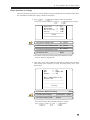
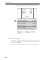
Basic operation of settings
The basic operating procedures for actually making settings of the M252A are described below. Here,
the "Automatic Print ON/OFF" setting is made as an example.
1. Press
[F] →
[ENT], and the following is printed.
To enter the setting mode, press
[1] →
[ENT] successively.
Cancel/End
--> ESC
Maintenance
--> 3-ENT
Option Setting --> 2-ENT
Setting
--> 1-ENT
==========================
Select
==========================
operating
To enter the setting mode:
[1] → [ENT]
To enter the option setting mode:
[2] → [ENT]
To enter the maintenance mode:
[3] → [ENT]
To cancel or end:
[ESC]
※ For details of the option setting mode and maintenance mode,
see their respective explanations.
2. Upon entry of the setting mode, the following is printed. Since the Date/
Time setting comes up when you enter the setting mode, move to the
desired item.
End
-->
Next
-->
Change-> -->
ESC
Number-ENT
ENT
Now => 2000/06/05 12:00
01:Date/Time
--------------------------------------------------Setting
-------------------------[ENT]
To make the Date/Time setting:
operating
To make other settings:
[Setting No.] → [ENT]
To end the setting mode:
[ESC]
Since the Automatic Print ON/OFF setting No. is [08],
press
[08] or
[8] →
[ENT].
21
4. For greater use of the printer
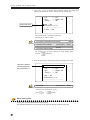
3. Upon entry of the Automatic Print ON/OFF setting, the following is
printed. The current set value is indicated on the "NOW" line.
End
-->
Next
-->
Change-> -->
Current set value
ESC
Number-ENT
ENT
Now => ON
08:Automatic Print
------------------------->> Next is 08
The current value is "Automatic Print ON".
Change the set value to "OFF".
To make the Automatic Print setting:
operating
[ENT]
To make other settings:
[Setting No.] → [ENT]
To end the setting mode:
[ESC]
For changing the set value, develop an input waiting state
with the
[ENT] key.
4. Since the following is subsequently printed, change the set value.
This part is printed.
> Input new number - ENT
The following lines
are printed with "3".
End
-->
Next
-->
Change-> -->
ESC
Number-ENT
ENT
Now => ON
08:Automatic Print
--------------------------
[Setting No.] → [ENT]
To change
operating
Since the OFF set value No. is [0],
press
[0] →
[ENT].
About setting Nos.
Setting Nos. facilitate identification of each setting.
See detailed explanations of each setting or the appendix "Setting mode list"(page 80).
22
4. For greater use of the printer
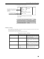
5. The changed set value is printed.
End
--> ESC
Next
--> Number-ENT
Change --> ENT
This part is for the next
setting (09 : Interval Print
ON/OFF).
NOW ==> Off
09:Interval Print On/Off
-------------------------New ==> Off
Changed set value
After changing the setting, go to the next setting
(step 2 and 3).
To make the Interval Print ON/OFF setting:
[ENT]
To make other settings:
[Setting No.] → [ENT]
To end the setting mode:
[ESC]
Cautions in setting
Some setting items are dependent on one another such that one setting does not become valid or cannot
be made until another setting is turned ON.
The setting items having a mutual dependence are shown below.
Dependence between settings
Source setting
Target setting
06: Print Every ON/OFF
07: Print Every Format
07: Print Every Format
20: Batch Total ON/OFF
20: Batch Total ON/OFF
07: Print Every Format
22: Code Selection
24: Code Table Selection
Ach
25: Code Table Selection
Bch
Description
The Print Every Format setting is not
valid until the Print Every ON/OFF
setting is turned [ON].
If the Print Every Format setting is
made at [8], [9] or [10], the Batch Total
ON/OFF setting cannot be turned
[ON].
The Print Every Format setting [8], [9]
or [10] cannot be selected until the
Batch Total ON/OFF setting is turned
[OFF].
The Code Table (A/Bch) setting cannot
be made until the Code Selection
setting is made at [2] or [3].
23
4. For greater use of the printer
Details of each setting
The details and operating method of each setting are explained below. For how to enter the setting
mode and its operating method, see the “Basics of settings” described in the previous chapter.
01: Date/Time
Change the date and time.
The date and time of the M252A are factory-set.
Correct it when it is necessary.
Name of setting
Initial value
Input format
01: Date/Time
The current time has been set at the time of delivery.
Y Y Y Y M M D D h h m m [ENT]
Year
Date Time (Fixed)
Caution
・Input all four digits for the year.
・Input "0" at the start of a one-digit month/date.
・Input the time on a 24-hour basis, and input "0" at the start of one-digit
hours/minutes.
・A battery is necessary for operation of the clock. The life of the
battery is approx. 8 years.
Example of setting - Setting 8:30 p.m., June 6, 2000 -
operating
Year
Date
→
Time
Fixing
→
24
4. For greater use of the printer
02, 03: Print Data Selection Ach/Bch
Select the type of data to be printed for each ch.
Four types of data can be selected.
Name of setting
Selection item
Reference
Caution
02: Print Data Selection Ach
03: Print Data Selection Bch
0. Gross (initial value)
1. Net
2. Tare
3. Indicated
・When printing values indicated by load cell indicators, normally set
the M252A at [3. Indicated]. Select Gross, Net or Tare only when you
want to specifically print these.
・When printing values indicated by digital indicators, normally set the
M252A at [3. Indicated].
The type of print data selected here is valid only when data is printed
through the SI/F. When data is printed through the BCD input or RS232C interface, input data is printed irrespective of the type selected
here.
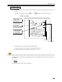
SI/F and indicators
Load cell indicator ...... The load cell indicator connected through the SI/F sends indicated, net, gross
and tare data at intervals of approx. 0.3 sec. irrespective of the indicated value
at the time. Since data to be printed can be selected from it on the printer side,
data other than the indicated value can be printed.
Load cell
indicator
Gross
SI/F
M252A
Indicated
Net
Gross
Tare
Net
Different types of data can be printed.
Digital indicator.......... The digital indicator connected through the SI/F sends the indicated value
at that time at intervals of approx. 0.3 sec.
Digital
indicator
Indicated
value
M252A
SI/F
Indicated
Indicated value
Different types of data cannot be printed.
25
4. For greater use of the printer
04, 05: Unit Selection Ach/Bch
Select the unit to be printed on Ach/Bch.
43 types of data can be selected.
Name of setting
Selection item
Initial value
Caution
04: Unit Selection Ach
05: Unit Selection Bch
See the "List of unit settings"(page 82).
02. kg
When "Double size" is selected under Print Every Format, the unit is
printed only up to four characters. If a unit of five or more characters is
selected, only the first four characters are printed.
06: Print Every ON/OFF
Select whether or not to print on roll paper.
Name of setting
Selection item
06: Print Every ON/OFF
0. OFF
1. ON (initial value)
Caution
・Since print data is stored in internal memory irrespective of whether
the setting is ON or OFF, sub totals and grand totals are not affected.
・If the setting is OFF, no printing will result.
Details of setting
ON........................... Data is stored in internal memory with printing on roll paper.
OFF......................... Data is simply stored in internal memory without printing on roll paper.
26
4. For greater use of the printer
07: Print Every Format
Select the print format of data.
13 types of print format can be selected.
Name of setting
Selection item
Reference
Caution
07: Print Every Format
0. Standard (initial value)
1. With time
2. With code
3. With time & code
4. With date
5. With date & code
6. Diagram
7. Double size
8. Double print
9. Double with cnt
10. Double with code
11. Ach <-- A or B
12. Through print
Ach and Bch are the same in unit, the grand total all of both ch's is
printed after printingthe total of each ch. If the units are different, the
grand totals of both ch's are not printed.
・When "Double size" is selected under Print Every Format, only the
first four characters are printed properly due to the print width. Be
careful when selecting the following units.
20:kg/m3
24:kg•cm
30:kg/cm2
・The count of "Ach <-- A or B" is numbered serially.
(Selection item 11)
Ach and Bch (SIF Ach) input data are all computed as Ach.
Make the unit and decimal place settings of Ach and Bch identical.
Otherwise, totals will not be able to be printed accurately.
1ch-added double print
Internal
computation
Ach input
Bch input
Ach
Normal double print
Internal
computation
Ach
Ach input
Internal
computation
Bch input
Bch
・If "12. Through print" is selected with no RS-232C interface (option),
"ERROR" is printed, resulting in no selection.
27
4. For greater use of the printer
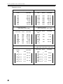
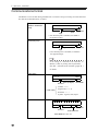
Examples of print
0. Standard (count, data)
Count
input data
Time
Count
1503
1502
1501
1500
1499
1498
1497
1496
500.5kg
450.2kg
1200.0kg
-385.8kg
55.0kg
0.0kg
1000.2kg
666.6kg
14:30
14:22
14:00
13:48
12:11
10:03
9:20
6:05
1503
1502
1501
1500
1499
1498
1497
1496
2. With code name
(code name, count, data)
Code name
FGHI
FGHI
JKLM
FGHI
NOPQR
JKLM
NOPQR
STUV
Count
Input data
7503
7502
2002
7501
1502
2001
1501
1001
500.5kg
450.2kg
1200.0kg
-385.8kg
55.0kg
0.0kg
1000.2kg
666.6kg
4. With date (date, time, count, data)
Count
Date
4
2000/10/18
3
2000/10/18
2
2000/10/18
1
2000/10/18
28
1. With time (time, count, data)
Input data
500.4kg
13:45
498.5kg
13:15
502.1kg
12:45
501.0kg
12:15
500.5kg
450.2kg
1200.0kg
-385.8kg
55.0kg
0.0kg
1000.2kg
666.6kg
3. With time & code
(time, code name, count, data)
Code name Count
Time
NOPQR
11:27
JKLM
11:26
NOPQR
11:26
STUV
11:25
Input data
1502
55.0kg
2001
0.0kg
1501
1000.2kg
1001
666.6kg
5. With data & code name
(date, time, code name, count, data)
Code name Count
Date
Time
Input data
SOLT
2000/10/18
SOLT
2000/10/18
SOLT
2000/10/18
SOLT
2000/10/18
Input data
Time
4
6643kg
19:30
3
5589kg
18:30
2
6002kg
17:30
1
5010kg
12:15
4. For greater use of the printer
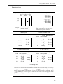
Examples of print
7. Double size print (data)
6. Diagram
Input data
Displacement diagram
Upper
limit
500.5kg
450.2kg
1200.0kg
-385.8kg
55.0kg
▲
-0.2
48.7
78.5
102.1
{
Example
Target
Value
▲
Lower
limit
Input data
Input data is printed horizontally
double size. However, the unit can be
printed only up to four characters.
TARGET: 50.0kg
RANGE: 50.0kg
9. Double print with count
8. Double print
Ach input data
Bch input data
Count
389.3kg
500.0kg
46
78.1kg
1444.0kg
45
420.2kg
150.5kg
44
10. Double print with code
STU
STU
HIGK
300.0kg
HIGK
450.0kg
HIGK
500.0kg
3
500.0kg
2
1444.0kg
1
150.5kg
389.3kg
78.1kg
420.2kg
11. Ach <-- A or B
Code Bch input data
Code Ach input data
STU
Count Bch input data
Ach input data
Count
Count Bch input data
Ach input data
389.3g
7
300.0kg
5
450.0kg
3
500.0kg
6
789.3g
4
389.3g
2
389.3kg
789.3kg
389.3kg
12. Through print
Characters sent from the RS-232C interface in ASCII code are printed as they are. Start/stop
through print with the
[PRINT] key. If the
[PRINT] key is pressed during
through print,an offline state will result, so that through print cannot be performed. If the
[PRINT] key is ressed again, an online state will result, so that through print can be
performed. FEED (paper feed) is valid only in an offline state.
29
4. For greater use of the printer
08: Automatic Print ON/OFF
Printing can be automatically produced by sending a print command from the SI/F or RS-232C
interface to the M252A. Select whether this Automatic Print is ON or OFF.
Name of setting
Selection item
08: Automatic Print ON/OFF
0. OFF
1. ON (initial value)
Caution
・Printing is always produced in the following conditions irrespective of
whether Automatic Print is ON or OFF.
・When the
[PRINT] key is pressed.
・When the PRINT terminal and COM terminal to the rear panel are
short-circuited.
・Since an automatic print command cannot be given from the BCD
input, it is necessary to give a print command on the printer for
printing print data from the BCD input.
Details of settings
ON........................... Printing is produced when a print command is sent from the SI/F or RS232C interface. For the print commands from the SI/F and RS-232C interface, see the instruction manual of each indicator and "RS-232C
interface(option)"(page 49).
OFF......................... Printing is not produced with a print command from the SI/F or RS-232C
interface.
■ For the print command from the SI/F, see the instruction manual of each connection indicator.
■ For the print command from the RS-232C interface, see "RS-232C interface(option)"(page 49).
09: Interval Print ON/OFF
Select whether or not to print at fixed intervals.
30
Name of setting
Selection item
09: Interval Print ON/OFF
0. OFF (initial value)
1. ON
Caution
Keys other than
[STOP] (to stop Interval Print) and
cannot be used during Interval Print.
[ENT]
4. For greater use of the printer
Details of settings
ON........................... Print is automatically produced at intervals of seconds set under
[10: Interval Seconds] (See below). Printing is not produced with a
print command from the SI/F or RS-232C interface.
OFF......................... Interval Print is not performed.
Timing of Interval Print
* Setting Interval Seconds at 5 seconds.
Interval Print
Start
5sec.
5sec.
1st time
End
5sec.
2nd time 3rd time
nth time
10: Interval Seconds
Set the interval for Interval Print in seconds.
Name of setting
Setting range
Initial value
Caution
10: Interval Seconds
1 - 9999 seconds
0003 seconds
The setting range of [Interval Seconds] varies depending on the [07:
Print Every Format] setting (page 27). Set [Print Every Format] before
setting [Interval Seconds].
When the [Print Every Format] setting is 00 or 01: 1 ~ 9999 seconds.
When the [Print Every Format] setting is 02 ~ 07: 2 ~ 9999 seconds.
When the [Print Every Format] setting is 08 ~ 11: 4 ~ 9999 seconds.
Example of setting -Setting 50 seconds/5000 seconds-
operating
50 seconds
→
Seconds
Fixing
→
5000 seconds
Seconds
Fixing
31
4. For greater use of the printer
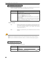
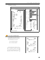
11: GT/ST Print Format
Select the print format of grand totals and sub totals.
Five types of formats can be selected.
Name of setting
Selection item
Reference
11: GT/ST Print Format
0. Standard (initial value)
1. With code
2. With ave/max/min
3. With statistical
4. With histogram
If Double print is selected under [Print Every Format] and Ach and Bch
are the same in unit, the grand total all of both ch's is printed after
printingthe total of each ch.
Examples of print
0. Standard
1. With code name
-----------------------GT
1250kg
COUNT
10
DATE
2000/07/05 01:25
-----------------------GT
1250kg
COUNT
10
CODE
ABCDE
DATE
2000/07/05 01:25
--- GRAND TOTAL
Ach ----- GRAND TOTAL
Ach ---
Direction of print
2. With avg./max/min
3. With statistical data
-----------------------R(MAX-MIN)
1903kg
MIN
554kg
MAX
2457kg
AVE
1352kg
σn
675kg
-----------------------H OVER TIMES
2
L OVER TIMES
1
RANGE
20kg
TARGET
100kg
GT
COUNT
CODE
DATE
13515kg
10
ABCDE
2000/08/02 21:39
--- GRAND TOTAL
Ach ---
R(MAX-MIN)
MIN
MAX
AVE
σn
GT
COUNT
CODE
DATE
1036kg
11
ABCDE
2000/06/21 13:01
--- GRAND TOTAL
32
122kg
0kg
122kg
94kg
32kg
Ach ---
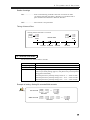
4. For greater use of the printer
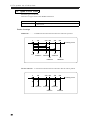
Examples of printing
4. With histogram
(Continued to the lower right)
L3
L4
LOWEST
84 ~
80 ~
~
88
83
79
H OVER TIMES
L OVER TIMES
RANGE
TARGET
1
1
20kg
100kg
R(MAX-MIN)
MIN
MAX
AVE
σn
51kg
72kg
123kg
103kg
14kg
GT
COUNT
CODE
DATE
1031kg
10
ABCDE
2000/06/21 13:01
--- GRAND TOTAL
Ach ---
Direction of print
-----------------------HI
1
U4
U3
U2
U1
T
L1
L2
L3
L4
0
2
1
3
0
1
1
0
0
LOW
1
HIGHEST
U4
U3
U2
U1
T
L1
L2
Times
121 ~
117 ~
112 ~
108 ~
103 ~
98 ~
93 ~
89 ~
120
116
111
107
102
97
92
Range
(Continued from the upper left)
In the case of Double print
Ach and Bch are the same in unit, the
grand total all of both ch's is printed
after printingthe total of each ch.
Ach: Code Name WXYZA
Bch: Code Name ABCDE
-----------------------GT
2300kg
COUNT
20
--- GRAND TOTAL ALL --GT
COUNT
CODE
DATE
1250kg
10
ABCDE
2000/07/05 01:25
--- GRAND TOTAL
If the decimal place setting of each
ch is different, automatic totaling
will result according to the ch with
a larger number of decimal places.
GT
COUNT
CODE
DATE
Bch ---
1050kg
10
WXYZA
2000/07/05 01:25
--- GRAND TOTAL
Ach ---
33
4. For greater use of the printer
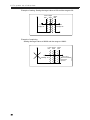
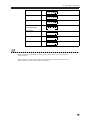
12: Types of Sub Totals
Select the types of sub totals.
There are two types of sub totals: Middle and Section.
Name of setting
Selection item
12: Types of Sub Totals
0. Middle sub (initial value)
1. Section sub
Details of settings
Middle sub ............. A middle sub total from the last total to this sub total is printed.
0
100
250 300
500
400
Printing count
ST
GT 100times
ST
250times
ST
400times
ST
500times
ST
300times
Section sub total .... A section sub total from the last sub total to this sub total is printed.
0
100
250 300
400
500
Printing count
GT
ST
100times
ST
150times
ST
100times
ST
50times
34
ST
100times
4. For greater use of the printer
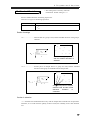
13, 15: Histogram Target Value Ach/Bch
14, 16: Histogram Range Ach/Bch
* These setting items also serve as the "Range over (U/L)" setting (page 69).
Set the target value and range (width from the target value) necessary to work out statistical data
and the histogram.
Name of setting
13,15: Histogram Target Value Ach/Bch
14,16: Histogram Range Ach/Bch
Input range
Histogram target value
Histogram range
Setting conditions
(Upper limit) = (Target value) + (Range) ≦ +99998
(Lower limit) = (Target value) - (Range) ≧ -99998
Explanation of
setting
・If data exceeding the range is input, U (upper limit exceeded) or
L (lower limit exceeded) is added to the print data.
0 ~± 99999 (initial value: +00000)
5 ~ 99998 (initial value: 99998)
・For switching the sign during input, use the
[- (hyphen)] key.
・Input a setting value excluding a decimal point.
Example)100.0 → 1000
・The range between the upper limit and lower limit are divided
into nine equal parts to produce histogram ranks.
・The numbers of pieces of data exceeding the upper limit and
lower limit are counted as H OVER TIMES and L OVER TIMES,
respectively.
・If any data exceeds the upper limit or lower limit at Print-Every time,
a range-over symbol is printed on the right-hand side of the data.
Data > Upper limit ⇒ ’U’
Data < Lower limit ⇒ ’L’
Caution
・Since addition of U and L covers all print data during printing, if the
histogram and diagram are not used, use maximum value (initial
value) and the target value of zero (0) (initial vlaue) as the range.
・The target value can be set only in a condition that U and L can be
printed. Before setting the target value, change the range value.
・If any target value is input not meeting the conditions, “Error” will be
printed, and then an automatic movement will be made to the range
setting of the corresponding ch.
Change the range setting value, and then set the target value again.
35
4. For greater use of the printer
Example of setting -Setting the target value at 100 and the range at 20-
Lower Target
limit
value
Upper
limit
L print
55.0kgL etc
0
U print
150.0kgU etc
80
100
120
Example of noprinting
-Setting the target value at 80000 and the range at 19999-
Lower Target
limit value
L print
60000kgL etc
0
36
60001
Upper
limit
(
80000
99999
No U print
More than 99999
cannot be
printed.
)
4. For greater use of the printer
* This setting item is necessary when the
GT/ST Print Format setting is 2 - 4.
17: Standard Deviation
Select a standard deviation calculating expressions.
There are two types of calculating expression.
Name of settings
Selection
17: Standard Deviation
0. σn (initial value)
1. σn-1
Details of settings
σn ........................... When all data in a group is used, and the standard deviation of the group is
obtained.
σn
Group
○
○
○
n
σn =
∑ ( χi – χ )
2
○
○
○
i=1
-----------------------n
○
○
○
All data in the group is used,
and the standard deviation is
obtained.
σn-1 ........................ Several pieces of sample data in a group are used, and the standard
deviation of the group is estimated from the sample data.
σn-1
Group
○
n
σn – 1 =
2
∑ ( χi – χ )
i=1
-----------------------n–1
○
○
○
○
○
○
○
○
Only several points of sample
data are used, and the overall
standard
deviation
is
estimated.
Caution in selection
σn-1 calculates the standard deviation only with the sample data extracted from all print data.
Therefore, if it is used when the quantity of data is small, the reliability of the value becomes
low.
37
4. For greater use of the printer
18: Data Adding ON/OFF
Select whether or not the print data is targeted for grand totals/sub totals.
Name of setting
Selection item
Caution
18: Data Adding ON/OFF
0. OFF
1. ON (initial value)
If Data Adding OFF is selected, printing is produced irrespective of the
setting of [06: Print Every ON/OFF].
Details of settings
ON........................... The print data is targeted for grand totals/sub totals.
OFF......................... The print data is not targeted for grand totals/sub totals.
" * " (asterisk) is printed at the end of the printed data.
Meaning of setting
This setting is for testing printing after changing the setting(s) of equipment. Normally use at
ON.
Example of setting
Actually, setting
operations (print)
for a change should
be performed.
GT
300.57kg
COUNT
3
DATE
2000/07/01 10:00
---- GRAND TOTAL Ach ---3
100.15kg
(Omitted)
2
100.56kg*
2
100.47kg*
(Omitted)
2
100.21kg
1
100.21kg
Changed to ON in
this interim.
Changed to OFF
in this interim.
19: PRINT Key ON/OFF
Select whether the
Name of setting
Selection item
Caution
[PRINT] key on the front panel is ON or OFF.
19: PRINT Key ON/OFF
0. OFF
1. ON (initial value)
This setting is irrelevant to the PRINT terminal on the rear panel and an
automatic print command from the SI/F or RS-232C interface.
Meaning of setting
Select [OFF] if you do not want to print through a careless operation of the automatic
equipment, etc.
38
4. For greater use of the printer
20: Batch Total ON/OFF
Set whether or not to find the batch total. If Batch Total is selected, the [FEED] terminal block
on the rear panel is switched to the [Batch Total Print] terminal block.
Name of setting
Selection item
20: Batch Total ON/OFF
0. OFF (initial value)
1. ON
Caution
・Batch Total can only be executed by short-circuiting [FEED] and
[COM] on the rear terminal block.
・If Double print is set, Batch Total cannot be turned ON.
Meaning of setting
Several small measurements are batched and printed as one measurement.
Raw glass materials
Silica
sand
Soda Lime Cullet
ash
Others
Mixer
Generally, raw materials of glass are mixer-agitated
materials including silica sand, soda ash, lime, cullet and
others. Batch Total prints how much raw glass materials are
mixed as a result of measuring each of these five types of
materials.
Examples of printing
(Continued to the lower right)
-------------------------BT
422.84kg
COUNT
2
DATE
2000/07/01 11:32
------ BATCH TOTAL ----10
100.11kg
9
10.06kg
8
2.11kg
7
10.06kg
6
300.50kg
------------------------BT
558.62kg
COUNT
1
DATE
2000/07/01 11:32
------ BATCH TOTAL ----5
4
3
Direction of print
225.82kg
20.55kg
2.01kg
2
10.08kg
1
300.16kg
-------------------------GT
937.02kg
COUNT
3
DATE
2000/07/01 11:32
--- GRAND TOTAL
Ach ---
------------------------BT
333.14kg
COUNT
5
DATE
2000/07/01 11:32
----- BATCH
5
4
3
2
1
TOTAL ----3.99kg
10.05kg
8.99kg
10.05kg
300.06kg
(Continued from the upper left)
39
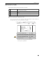
4. For greater use of the printer
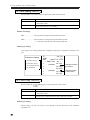
21: Feed Lines
Set the number of lines for feeding paper after Print Every, ST (sub total print) and GT (grand
total print).
Name of setting
Setting range
Initial value
Caution
21: Feed Lines
0 - 9 (lines)
0
Paper is fed by the number of lines set under [Feed Lines] after Print
Every, ST, GT, BT, Sample Print and Test Print. Paper is always fed by
one line with the
[FEED] key.
Meaning of setting
Immediately after every printing, the printed data cannot be checked because the paper has not
yet been ejected from the ejection slot. Set 3 - 4 lines for visually checking every piece of
printed data.
Example of
printing
DATE
2000/07/01 13:30
--- GRAND TOTAL Ach --3
100.15kg
2
100.18kg
1
100.21kg
Feed
lines
22: Code Selection Method
Select a method for selecting codes.
Name of setting
Selection item
Caution
22: Code Selection Method
Setting
0
(initial value)
1
2
3
Ach
Key Board
Bch
Key Board
Option
Key Table
Option Table
Key Board
Key Table
Key Table
If Keyboard/Option is selected, code names can be selected. If Key
Table/Option Table is selected, codes can be selected from code tables.
Details of setting
Keyboard................ Code names can be selected with the keys on the front panel.
Option ..................... Code names can be selected through RS-232C interface or BCD input
(option).
Key table ................ Codes can be selected with the keys on the front panel.
Option table ........... Codes can be selected through the RS-232C interface or BCD input
(option).
40
4. For greater use of the printer
23: Number of Code Digits Designation
Set the number of code digits for classification.
Name of setting
Setting range
Initial value
Caution
23: Number of Code Digits Designation
0 - 6 (digits)
6
When using code tables, set the Number of Code Digits to two digits. If
it is set to three or more digits, normal classification cannot be
performed.
Details of setting
Usually up to six digits can be used for code names, but if the Number of Code Digits is set,
code names are classified by the set number of digits from their ends, so that code names having
a different beginning can also be classified as the same for totaling.
Example) The Number of Code Digits is set at two digits.
0000 01
①
0001 01
①
0001 02
②
0002 01
①
1001 02
②
This part is printed but is not
the target of classification for
totaling.
Classification for
totaling
Classification is performed only
with the last two digits, which are
the target of totaling.
24, 25: Code Table Registration Ach/Bch
Register a code table. What should be registered are codes and corresponding code names for
the code table.
Name of setting
24: Code Table Registration Ach
25: Code Table Registration Bch
Maximum number 64 (32 for each ch)
of codes
Caution
・The code table can only be registered with the keys on the front panel.
・For details of the code table, see "Classification by code name and
code table"(page 56).
41
4. For greater use of the printer
M E M O
42
5
Optional interface
BCD input and RS-232C interface
■ BCD input (option)
■ BCD input settings
■ RS-232C interface(option)
■ RS-232C settings
■ Communications format
■ DC power source
44
48
49
50
52
54
43
5. Optional interface
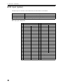
BCD input (option)
The BCD input is an interface to take in BCD data, and code numbers to the M252A.
Applicable connector
Input data
Input equipment
Input logic
DDK-manufactured 57-30500 or equivalent
Print data, codes (number, space, hyphen)
Digital switch, DIP switch, BCD output equipment, etc.
Select negative logic or positive logic.
BCD input pin assignment
No
1
2
3
4
5
6
7
8
9
10
11
12
13
14
15
16
17
18
19
20
21
22
23
24
25
44
COM
Print data
Print data
Print data
Print data
Print data
Print data
Print data
Print data
Print data
Print data
Print data
Print data
Print data
Print data
Print data
Print data
Print data
Print data
Print data
Print data
Code
Code
Code
Code
1
2
4
8
10
20
40
80
100
200
400
800
1000
2000
4000
8000
10000
20000
40000
80000
1
2
4
8
No
26
27
28
29
30
31
32
33
34
35
36
37
38
39
40
41
42
43
44
45
46
47
48
49
50
Code
10
Code
20
Code
40
Code
80
Code
100
Code
200
Code
400
Code
800
Code
1000
Code
2000
Code
4000
Code
8000
Code
10000
Code
20000
Code
40000
Code
80000
Code
100000
Code
200000
Code
400000
Code
800000
Over input (See page 68)
Minus input
Reserved
Strobe input
Reserved
5. Optional interface
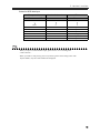
Codes for BCD data input
Binary number
MSB LSB
Hexadecimal number
Print
Character
0000
0
0
1001
1010
1011
1100
1101
9
A
B
C
D
9
Space
Space
Space
1110
1111
E
F
‐ (Hyphen)
Space
Space
Note
- When you input a code from BCD input, please choose 1or 3 of setting item
"code selection ".
- When you make a code print by print every format, please choose thing with a code.
By the default, only the count and data are displayed.
45
5. Optional interface
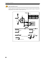
Input equivalent circuit
A signal is inputted to the signal input circuit by short-circuiting or opening the input terminal and the
COM terminal. Short-circuiting is effected by means of a contact (such as a relay or a switch) or a
noncontact (such as a transistor or an open-collector TTL).
M252A
Vcc
← inside
outside →
Logic Negative Positive
+5V
Open
OFF
ON
Short
ON
OFF
approx.
IC=0.5mA
COM
push
switch
1
toggle
*
IN
relay
transistor
IN
TTL open collector output
short-circuited when IN is ‘H’
46
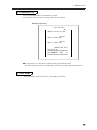
5. Optional interface
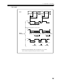
Read command
Valid data
Data
Valid data
MAX. 5ms
MAX. 5ms
MIN. 15ms
MIN. 15ms
OFF
ON
MIN. 10ms MIN. 10ms
When ON continues for 1 sec or more
OFF
ON
Read
command
Approx.
100 100 100 100ms
100 100 100ms
Approx.
1 sec or more ms ms ms or more 1 sec or more ms ms or more
Sampling
Sampling
OFF
ON
1 sec or more
Sampling
1 sec or more
Sampling
1 sec or more
Sampling
* When the read command is short-circuited for 1 sec or more,
data is taken in asynchronously at intervals of 100ms.
47
5. Optional interface
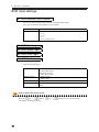
BCD input settings
41: BCD Decimal Point Position
Select a decimal point position to input data through the BCD input.
Five types of decimal point positions can be selected.
Name of setting
Selection item
41: BCD Decimal Point Position
0. *.****
1. **.***
2. ***.**
3. ****.*
4. ***** (initial value)
42: BCD Data Logic
43: BCD Minus Logic
44: BCD Over Logic
45: BCD Strobe Logic
Select a BCD input logic.
Name of setting
Selection item
Initial value
Reference
42: BCD Data Logic
43: BCD Minus Logic
44: BCD Over Logic
45: BCD Strobe Logic
0. Negative logic
1. Positive logic
0. Negative logic (all)
Logic settings can be made separately for Data/Code, Minus, Over, and
Strobe.
How to enter the option mode
Press the
[F] →
[ENT] see "Basics of settings"(page 20).
48
[2] →
[ENT] keys in order. For details,
5. Optional interface
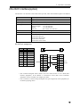
RS-232C interface(option)
The RS-232C is an interface to take in RS-232C spec data, codes and command signals to the M252A.
Signal level
Transmission distance
Transfer system
Transfer speed
Bit configuration
Code
Connector
Necessary settings
RS-232C spec
Approx. 15m
Start/stop synchronous system,full duplex communications
1200, 2400, 4800 or 9600 bps selection
Start bit:
1
Character length:
7 or 8 bit selection
Stop bit:
1 or 2 bit selection
Parity bit:
Non, odd or even selection
ASCII
D-Sub 9pin male (CN33)
46: RS-232C transmission rate
47: RS-232C parity bit
48: RS-232C data/stop bit
49: RS-232C terminator
50: RS-232C answer mode
RS-232C pin assignment
No.
1
2
3
4
5
6
7
8
9
I/O
‐
IN
OUT
OUT
*
‐
OUT
OUT
‐
Description
(Unused)
RxD
TxD
DTR
SG
(Unused)
RTS
CTS
(Unused)
D-Sub9pin
female
M252A
Crossing cable
D-Sub9pin
female
1
(Unused)
1
DCD
2
RxD
2
RxD
3
TxD
3
TxD
4
DTR
4
DTR
5
SG
5
SG
6
(Unused)
6
DSR
7
RTS
7
RTS
8
CTS
8
CTS
9
(Unused)
9
RI
PC or
the like
* This connection diagram shows cables in the case where the PC in use is DTE (data
terminal equipment). If the M252A is connected to DCE (data circuit terminator
equipment) such as a modem, use straight type cables.
* Also, recheck the connector shape and signal lines (pin assignment) of the equipment you
use before preparing cables.
49
5. Optional interface
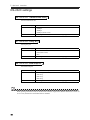
RS-232C settings
46: RS-232C Transmission Rate
Select transmission rate
Name of setting
Selection item
Caution
46: RS-232C Transmission Rate
0. 1200bps
1. 2400bps
2. 4800bps
3. 9600bps (initial value)
The setting must be the same as the connecting equipment.
47: RS-232C Parity Bit
Select parity bit.
Name of setting
Selection item
Caution
47: RS-232C Parity Bit
0. Even
1. Odd (initial value)
2. Non
The setting must be the same as the connecting equipment.
48: RS-232C Data/Stop Bit
Select data/stop bit.
Name of setting
Selection item
Caution
48: RS-232C Data/Stop Bit
0. 7bit 1stop (initial value)
1. 7bit 2stop
2. 8bit 1stop
3. 8bit 2stop
The setting must be the same as the connecting equipment.
Note
When printing a katakana code, set the RS-232C character length of the M252A and the PC to 8 bits. If
set to 7 bits, transmission of katakana data is disabled.
50
5. Optional interface
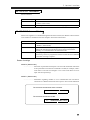
49: RS-232C Terminator
Select terminator.
Name of setting
Selection item
Caution
49: RS-232C Terminator
0. CR
1. CR+LF (initial value)
The setting must be the same as the connecting equipment.
50: RS-232C Answer Mode
When receiving data or a command through the RS-232C interface, the M252A returns with the
received data or command to the host computer. Select this return format.
Name of setting
Selection item
Reference
Caution
50: RS-232C Answer Mode
0. MODE 0 (M250 mode) (initial value)
1. MODE 1 (M252 mode)
Select the M250 mode when using software specifically prepared for
UNIPULSE-manufactured intelligent printer M250 in the M252A.
Normally, it is recommended to use the M252 mode.
When preparing software such that two or more commands are sent
successively, be sure to program the software so that the next command
is sent after receiving a response .
Details of settings
MODE 0 (M250 mode)
........................... Echo-back is performed with respect to all received commands. Echo-back
is also performed even when the command is invalid (for example, when a
code name is received even though it is set so that code names are to be
input with front panel keys)
MODE 1 (M252 mode)
........................... Information regarding whether or not a command has been executed is
returned as it is added to the header with respect to all received commands.
The received command has been executed.
O K :
Received command CR LF
The received command is invalid.
N G :
Received command CR LF
51
5. Optional interface
Communications format
The M252A receives all data through the RS-232C as character strings consisting of ASCII characters.
For data and command formats, see below.
Data
(without automatic
print)
F A 0 ± 9 9 9 .
9 9 CR LF
Command
5 digits + decimal Terminater
point
Sign
* If no decimal point is included, 0 is added to
the uppermost digit.
Data
(automatic print)
F A 1 ± 0 9 9 .
9 9 CR LF
Command
5 digits + decimal Terminater
Sign
* If no decimal point is included, 0 is added to
the uppermost digit.
Note
If the setting of "Automatic Print ON/OFF" of
M252A is OFF, no printing will be performed.
See "08 : Automatic Print ON/OFF" (page 30 )
for details.
Code Name
F A 2
CR LF
Command
Code (6 digits)
Unused
Terminater
{
Code name
Number : 0 - 9
English letter : A - Z
Katakana : ア - ン
Symbol : hyphen, slash, Space
Code table
F A 2
CR LF
Command
Space
Terminater
Unused
Code table No.
Code table No.: 00 - 31
52
5. Optional interface
Delete last data
F B 0 CR LF
GT print
F B 1 CR LF
ST print
F B 2 CR LF
Data print
(latest data print)
F B 3 CR LF
Paper feed
F B 9 CR LF
Batch total print
F B 4 CR LF
Date/Time print
F B 6 CR LF
Note
- When you input a code with RS-232C interface, please choose 1or 3 of setting item
"code selection ".
- When you make a code print by print every format, please choose thing with a code.
By the default, only the count and data are printed.
53
5. Optional interface
DC power source
For the M252A, DC power source specification can be selected at order-time.
+
-
DC IN
Red
Black
Connect the positive (+) side of the power source to the red screw side of the terminal block on
the back of the M252A, and its negative (-) side to the black screw side.
Input voltage range
DC12V ~ 24V
+15%
-15%
(voltage between terminals of the M252A)
Note
Be aware that the voltage drops depending on the wire thickness and length.Also, never input an
AC power source. Doing so will cause a failure.
Current consumption (25 ℃ ,With BCI option)
Condition
DC12V
DC24V
Wait
Approx.150mA rms
Approx.100mA rms
Print Every
Approx.800mA rms
Approx.400mA rms
Current consumption
(max.)
10A peak
(Approx.2msec)
2A peak
(Approx.2msec)
※ When the histogram format is printed, current consumption is maximum.
Inrush current (25 ℃ ,With BCI option)
DC12V
800mA peak (150msec)
54
DC24V
1A peak (150msec)
6
Advanced use
Various functions of the M252A
■ Classification by code name
and code table
■ Maintenance mode
■ Over print
■ Delete print
■ Initialization
■ ROM version print
■ Date print
56
63
68
70
71
71
72
55
6. Advanced use
Classification by code name and code table
The M252A can total sub totals and grand totals on the basis of code names assigned to print data. Up
to 32 code names can be registered for each ch.
Maximum number of 32 code names for each ch
code names
Method of registration ・A registration waiting state is developed by inputting with front panel
keys and pressing
Input format
Usable characters
Code name
designation method
[A] →
[ENT]
(
[B] →
[ENT] on Bch).
・Input through the RS-232C. (page 51)
###### (6 digits at the maximum)
umbers, English letters, katakana, synbols (-, *, /, space)
Front panel keys, RS-232C, BCD input
Registered code names
It is possible to total on a
code-by-code basis.
ABCDE
WXYZA
Measuring
NOPQR
…
Totaling
Up to 32 code names
for each ch
Measuring
Totaling
Measuring
Totaling
56
6. Advanced use
Code name registration performance with front panel keys
Input code names by using numeral keys from
[1] to
[0], and
[-(ST)],
[SP(GT)],
[(DEL)] keys. Since each numerical key is assigned approx. 10 characters, press the key until a
desired character is displayed results. (This is designateed a key group.) For the list of characters
assigned to each group, see the appendix "Character input table"(page 83).
- For inputting a character in the same group successively, press
the virtual cursor one character ahead.
[DEL] once to move
- For inputting a character in a different group, input it successively. It is not necessary to
press
[DEL].
The basic operating procedures for actually setting the M252A actually are described below. Here, the
code name "ABCDE" is registered to Ach as an example.
1. Press
[A] →
code name input.
[ENT], and the following is printed to start
>> Input Code A - ENT
>> Now Code A
[ABC
]
2. Input the code name as follows.
(Actually, it is
not indicated.)
operating
A
Press
two times.
A
Virtual cursor position
B
Press
three times.
AB
C
Press
two times.
ABC
D
Press
three times.
ABC D
E
Press
four times.
ABCDE
Upon completion of input, fix with
3. The registered code name is printed.
>> Code name is [ABCDE
]
57
6. Advanced use
Code table - Difference from code names By registering code names corresponding to 2-digit numbers (code table numbers) between 00 and 31
beforehand (The same also applies to Bch.), a registered code name can be designated and printed by
specifying its table number without inputting its code name every time you select a code name. If the
code table is not used, it is necessary to designate the code name by inputting it with front panel keys or
through an option.
Code table
Code names
Code table number Corresponding
code name
Registered
code name
00
STUV
STUV
01
FGHI
FGHI
02
NOPQR
NOPQR
│
│
│
31
│
│
│
JKLM
│
│
│
JKLM
By specifying a code table number,
the corresponding code name is
designateed, printed and classified.
For designateing NOPQR, input "02"
to the last two digits.
Maximum number of
code names
Method of
registration
Input format
Usable characters
Code
namedesignateing
method
By specifying a code name, the
code name is designateed,
printed and classified. For
designateing NOPQR, input
"NOPQR".
32 code name for each ch. Ach (00 - 31) Bch (32 - 63)
Register under [24 (25): Code Table Ach (Bch)] in the
setting mode.
Code
## (00 - 63 to the last two digits)
Code name
###### (6 digits at maximum)
Numbers, English letters, katakana,
symbols (-, *, /, space)
Front panel keys, RS-232C, BCD input
However,
58
Registration
Ach
:00 ~ 31
Bch
:32 ~ 63
Call
Ach
:00 ~ 31
Bch
:00 ~ 31
6. Advanced use
Code table registration performance
Code table registration is almost the same as the abovementioned [Code name registration
performance] except for inputting table numbers corresponding to code names at the beginning.
The basic operating procedures actually for setting the M252A are described below. Here, the code
table number "01" and code name "NOPQR" are registered on Ach as an example.
1. Select “2. Key Table” or “3. Option Table” under [22: Code Selection
Method].
2. Set “2 digits” under [23: Number of Code Digits Designation].
3. Referring to "4. For greater use of the printer" (page 19), enter [24: Code
Table Registration Ach] in the setting mode.
End
-->
Next -->
Input -->
ESC
Number-ENT
ENT
24:Code Table Ach
==========================
>> Next is 24
To enter code table registration: [ENT]
operating
To make other settings:
[Setting no.] → [ENT]
To cancel or end:
[ESC]
For code table registration, press
[ENT].
4. Since the following is printed, input the code table number in a 2-digit
number.
00 to 31 - ENT
>> Input table number
operating
Here, press
[01] →
[ENT].
59
6. Advanced use
5. Since the following is printed, input the code name successively.
operating
>> Input code name - ENT
>> Now Code
[GH
]
>> Table number is 01
Registered
table number
Referring to [Code registration performance], input the code
name.
6. The registered code name is printed, and code table registration is
completed.
>> Cancel ---> ESC
00 to 31
ENT
>> Input table number
>> Code name is [NOPQR ]
Registered code name
To proceed with registration: [Code table number] → [ENT]
To cancel or end:
[ESC]
Method of code table registration
For the method of code table registration, also see "Code Table Registration Ach/Bch" (page 41).
60
6. Advanced use
How to designate a code name/code table
For designating a code name, input the code name, and for designating a code table, input the table
number. There are some restrictions in interface for designating a code name/code table.
Select whether to designate a code name or code table and whether to use front panel keys or an
optional interface under [22: Code Name Selection Method] in the setting mode.
Selecting with front panel keys
Press
[A] →
[ENT] (
[B] →
[ENT] on Bch) in the print mode, and
a code name selection state is developed. In the case of a code name, input by the same
operation as the abovementioned method of registration. In the case of a code table, it is
requested to input the table number, so press [Del] four times, and then input a 2-digit number.
(If the first digit and the second digit are the same, press [Del] once after inputting the first digit,
and then input the second digit.)
Selecting through an option
See the explanations for each option.
List of methods of code name/code table selection
Code
Front panel keys
BCD input
RS-232C
Code table
Ach
Bch
Ach
Bch
○
△ (Note)
○
×
○
○
○
×
○
×
○
×
(Note) Codes that can be selected through the BCD input are only numbers,
spaces and hyphens.
List of code table registration methods
Code table
Ach
Bch
Front panel keys
BCD input
RS-232C
○
×
×
○
×
×
Note
Code table numbers can be selected through an option only to Ach. Selection cannot be made to Bch.
61
6. Advanced use
Note
Be careful when over 32 types of codes or other than 00~31 codes is selected from front panel or
option,accumulation is conducted taking items below as selected
Code: Code printed first after calculated GT
Example) When 000032 is selected after 32 types of code 000000~000031 were printed.
After calculated GT.
Accumulation is conducted
taking the code first printed
as selected.
In this case 000005 is
selected.
Input
Print
000032
000006
000005
000003
000005 4 100kg
000006 1 100kg
000005 3 50kg
000003 1 100kg
000005
000001
000001
000005
000005 2 100kg
000001 2 100kg
000001 1 100kg
000005 1 50kg
Print direction
Code Table: Code registered in Code table 00
Example) When 32 in Code Table is selected.
Input
Accumulation is conducted
taking the Code registered
in Code table as selected.
In this case, ABCDE is
selected.
32
06
05
03
00
05
01
01
05
Print
ABCDE
FGHIJ
KLMNO
PQRST
ABCDE
KLMNO
UVWXYZ
UVWXYZ
KLMNO
2 100kg
1 100kg
3 50kg
1 100kg
1
50kg
2 100kg
2 100kg
1 100kg
1 50kg
Print direction
62
6. Advanced use
Maintenance mode
In the maintenance mode, operations of the M252A are checked.
1 Test Print
All characters that can be printed by the M252A are printed.
The data input status is printed.
Print Every and GT/ST Print formats are printed.
2 Sample Print
3 Self Test
The ROM and RAM of the M252A are tested, and the results are
printed.
A list of current parameters of the M252A is printed.
4 Parameter List
5 Test Mode
For factory check (Do not use).
Method for operating the maintenance mode
How to enter each item in the maintenance mode and procedures for each execution are
described below. Here, test print is performed as an example.
1. Press
[F] →
[ENT], and the following is printed.
To enter the maintenance mode, press
[3] →
[ENT]
successively.
-------------------------Cancel/End
--> ESC
Maintenance
--> 3-ENT
Option Setting --> 2-ENT
Setting
--> 1-ENT
==========================
Select
==========================
operating
To enter the setting mode:
[1] → [ENT]
To enter the option setting mode:
[2] → [ENT]
To enter the maintenance mode:
[3] → [ENT]
To cancel or end:
[ESC]
* For details of the setting and option setting modes,
see the respective explanations.
63
6. Advanced use
2. Since a list of items in the maintenance mode is printed, select a target
item.
-------------------------Cancel/End
-->ESC
Test Mode
-->5-ENT
Parameter List
-->4-ENT
Self Test
-->3-ENT
Sample Print
-->2-ENT
Test Print
-->1-ENT
--------------------------------------------------Maintenance
==========================
operating
To perform a test printing:
[1]→ [ENT]
To perform a sample printing:
[2]→ [ENT]
To perform a self test:
[3]→ [ENT]
To print a parameter list:
[4]→ [ENT]
To enter the test mode:
To cancel or end the maintenance mode:[ESC]
Since the item No. of Test Print is [1], press
[1] →
[ENT]. As soon as
[ENT] is pressed, a test
printing starts.
Cautions in maintenance mode
In the maintenance mode, each operation starts as soon as selection is made from the above
menu ([item No.] →
[ENT]). A confirmation message as in the setting mode and in the
option setting mode are not printed.
The test mode is an item for a factory check. Do not use this mode. (It is password-locked.)
64
6. Advanced use
1: Test Print
All characters that can be printed with the M252A, and the input data/status of each I/F are
printed.
Test print is executed by pressing
[1] →
[ENT] in the maintenance mode.
Sample of printing
Strobe ON
Strobe OFF
Code input
Print data input
T: Over OFF
O: Over ON
Built-in font
Input data/status
The SIF Bch status is printed only for double printing.
For BCD, printing results only when a BCD option is attached.
The data input status from the BCD IN connector is shown.
It is judged that no valid data is input if the print data part of the BCD print data input is other than 0 to
9 as follows:
T + EA001
(Printing of print data input values is disabled.)
65
6. Advanced use
2: Sample Print
Print Every and GT/ST Print formats are printed.
Test print is executed by pressing
[2] →
[ENT] in the maintenance mode.
Sample of printing (partial)
(↑ Print continues.)
************************
** SAMPLE PRINT No.3 **
************************
A---00 9876
12345kg
************************
** SAMPLE PRINT No.2 **
************************
05:09 9876
12345kg
************************
** SAMPLE PRINT No.1 **
************************
9876
12345kg
************************
** SAMPLE PRINT No.0 **
************************
■ As a sample, 180 lines are printed in total (approximately 65cm).
3: Self Test
The ROM and RAM of the M252A are tested, and the results are printed.
Press
starts.
[3] →
[ENT] in the maintenance mode, and the buzzer sounds and the test
Results of check
Results of test
{
Normal :〇
Abnormal:×
------------------------->> SUM:2AE
>> ROM: 〇
>> RAM: 〇
>> Checking...
-------------------------* The description of SUM varies depending on the ROM version.
If the result of Self Test is × or the test does not finish normally, the M252A may be faulty.
Ask your deaer representative or for sevicing.
66
6. Advanced use
4: Parameter List
A list of current parameters of the M252A is printed.
If a code table is used, code table setting values are also printed.
Sample of printing
(↑ Print continues.)
kg
04:Unit Selection Ach
Gross
03:Print Data Bch
Gross
02:Print Data Ach
2000/07/01 05:11
01:Date/Time
************************
** PARAMETER LIST
**
************************
■ As a parameter list, 100 lines are printed in total (approximately 35cm).
For double printing with use of a code table, 170 lines are printed (approximately 60cm).
5: Test Mode
The initial setting mode by the factory, and locked by password.
67
6. Advanced use
Over print
Print data out of the range set by the connecting indicator or the M252A is identified by this function.
There are two types of over print: over status (R) and range over (U/L).
Over status (R)
If the indicator side causes a LOAD (A/D converter input over), OFL1 (net>99999) or zero
abnormality, "R" is added after printed data, and the data is not added to grand totals/sub totals. It is not
counted up either.
Example of printing
EFGHI
EFGHI
EFGHI
EFGHI
EFGHI
EFGHI
EFGHI
4
3
3
3
2
1
1
563kg
1356kgR
1356kgR
849kg
1000kg
1356kgR
150kg
Not counted up.
Over status
GT (grand total)
-----------------------GT 2562kg
COUNT
4
CODE
EFGHI
DATE
2000/07/04 02:36
--- GRAND TOTAL
Ach ---
With the SI/F, over status is automatically sent from the indicator. With the BCD input, over print is
performed when a signal is input to pin No.46 [over input].
Note
Over status is printed because the indicator side has a problem. The problem cannot be solved by
setting on the printer side.
68
6. Advanced use
Range over (U/L)
If the range set under Target Value Ach (Bch) and Range Ach (Bch) is exceeded, the print is added
after printed data. If the upper limit is exceeded, "U" is printed, and if the lower limit is exceeded, "L"
is printed.
(Example) When the target value is set at 100, and the range at 20.
Lower Target
limit value
L print
55.0kgL etc
0
Upper
limit
‘U’ print
Measurement value
> Target value + Range
U print
150.0kgU etc
80
100
EFGHI
EFGHI
EFGHI
EFGHI
EFGHI
EFGHI
EFGHI
‘L’ print
Measurement value
< Target value - Range
120
7
6
5
4
3
2
1
68kgL
142kgU
121kgU
89kg
107kg
79kgL
120kg
GT (grand total)
Upper limit exceeded
Lower limit exceeded
-----------------------GT 726kg
COUNT
7
CODE
EFGHI
DATE
2000/07/04 02:36
--- GRAND TOTAL
Ach ---
■ If range over (U/L) and over status (R) (See the preceding page.) occur at the same time, over status
(R) is printed.
■ Range over is a guide for users to know whether or not printed values exceed the range. Sub totals
and grand totals are not affected.
69
6. Advanced use
Delete print
Use if you want to delete printed data (when you do not want to add the data to subtotals/grand totals).
Only one piece of the last printed data can be deleted.
Press
[DEL] →
[ENT] in the print mode, and the data is deleted.
Example of printing
EFGHI
EFGHI
EFGHI
EFGHI
EFGHI
EFGHI
EFGHI
5
4
4
4
3
2
1
119kg
113kg
81kg81kg
96kg
111kg
100kg
Data you want to delete
The previously printed data is
reprinted as it is marked with “-”
indicating deletion, and is deleted
from the grand total/sub total data.
GT (grand total)
-----------------------GT 539kg
COUNT
5
CODE
EFGHI
DATE
2000/07/04 02:36
--- GRAND TOTAL
Ach ---
■ The data that can be deleted is only the previously printed data.
Current value
EFGHI
EFGHI
EFGHI
EFGHI
EFGHI
5
4
3
2
1
119kg
81kg
96kg
111kg
100kg
Note
■ Delete print cannot be performed twice or more successively.
■ In the case of double printing, delete print can be performed only for Bch.
70
Can be deleted.
Cannot be deleted.
6. Advanced use
Initialization
The internal memory of the M252A is completely cleared, and the parameters are restored to their
factory default settings.
1. Turn on the power while pressing the
[A] key.
2. Since the following is printed, press
[ENT].
Cancel --> ESC
OK
--> ENT
----All data initial----
operating
To execute initialization:
[ENT]
To cancel initialization:
[ESC]
3. If the following is printed, initialization is successful.
----------------------->> Complete
Note
■ Deleted data or settings cannot be restored. Carefully perform this operation.
ROM version print
Press
[6] →
[ENT] in the print mode, and the ROM version is printed.
-----------------------Ver.1.03
------------------------
When the version is printed, the option name(s) is printed if any.
Ver.5.00
Ver.5.00
Op
Op
232
BCD
71
6. Advanced use
Date print
Press
[DATE] →
[ENT] in the print mode, and the current time is printed.
DATE
72
2000/07/04 23:19
7
Troubleshooting
■ Classification of trouble
■ The printer does not operate properly
■ The printer does not function properly
■ Others
74
75
77
78
73
7. Troubleshooting
Classification of trouble
Find applicable trouble out of the following, and take remedies according to the reference page. If
printing still cannot be generated properly, check the ROM version of the M252A body (See page 71)
and contact us.
The printer does not operate properly.
The M252A does not start............................................................................................. P.71
Printing is not generated................................................................................................ P.71
Printing is not generated even if the
[PRINT] key is pressed.......................... P.72
Although the printer head is running, nothing is printed. ............................................. P.72
Printing stops while printing ......................................................................................... P.72
Values different from those indicated by the load cell indicator are printed................. P.72
The printer does not function properly.
Printed counts are wrong............................................................................................... P.73
Values of sub totals/grand totals are wrong................................................................... P.73
Others
Printing has been generated by mistake. ....................................................................... P.74
The target value cannot be set. ...................................................................................... P.74
A pink line appears at the left end of the roll paper. ..................................................... P.74
The buzzer sounds when carrying out printing. ............................................................ P.74
74
7. Troubleshooting
The printer does not operate properly
Trouble 1
The M252A does not start.
Cause 1
The M252A is not connected to a power source.
Remedy1
Check that the power cord is fixed properly.
Cause 2
If the power LED does not light even though the M252A is connected to a power source,
the fuse may have blown.
Remedy1
Since the fuse has been installed inside the M252A, disassembly is necessary for
replacement. Therefore, it should be replaced by UNIPULSE. Consult your dealer
representative or UNIPULSE.
Trouble 2
Cause 1
Printing is not generated.
Printing is not generated until the data input terminals (SI/F, BCD input, RS-232C) are
connected properly and print data is sent.
Remedy1
Check to see if the connectors are inserted properly, and check for broken wires and
miswiring.
Remedy2
Check that the equipment sending data to the M252A (indicator sending SI/F signals, PC
sending RS-232C signals, etc.) operates normally.
Remedy3
In the case of a connection through the BCD input, check that the M252A and target
equipment are consistent in logic.
Remedy4
In the case of a connection through the RS-232C, check that the M252A and target
equipment are consistent in communication conditions. Settings that must be consistent
include transmission rate, character length, start bit, stop bit and parity bit.
Cause 2
Printing is not generated if the Print Every ON/OFF setting is OFF.
Remedy1
Make the Print Every ON/OFF setting at ON.
75
7. Troubleshooting
Cause 3
The printer is clogged with dust or jammed with paper.
Remedy1
Open the push panel, and check the mechanical part of the printer. Remove dust with air
or the like.
Remedy2
In the case of a paper jam, the printer is locked, so that [Print] and [Feed] cannot be used.
It may cause some trouble if you pull the paper fast or backward when you remove the
paper. Please pull the paper forward slowly and straight to remove it after stopping the
paper feed.
After removing paper, turn the power off and on again.
Trouble 3
Printing is not generated even if the
Cause 1
The
Remedy1
Referring to "Print Key ON/OFF"(page 38), make the
Trouble 4
[PRINT] key is pressed.
[PRINT] Key setting is OFF.
[PRINT] Key setting ON.
Although the printer head is running, nothing is printed.
Cause 1
A ribbon cassette has not been installed, or the ribbon cassette is out of ink.
Remedy1
Referring to "Installing a ribbon cassette"(page 8), install or replace the ribbon cassette.
Trouble 65
Trouble
Cause 1
Values different from those indicated by the load cell
indicator are printed.
SI/F signals from the load cell indicator include indicated and various kinds of weight
data irrespective of the value indicated by the indicator at that time.
Remedy1
Select data to be printed on the printer side. Set referring to "Print Data Selection Ach/
Bch" (page 25).
76
7. Troubleshooting
The printer does not function properly
Trouble 1
Cause 1
Printed counts are wrong.
Counts are stored in battery-required memory. If the power is turned off and on again
with the battery exhausted, a problem occurs such that printing is not counted normally.
Remedy1
The battery needs to be replaced. Since the battery should be replaced by UNIPULSE,
contact your dealer representative. The average life of the battery is approx. 8 years. The
time may also be incorrect if the battery is exhausted.
Trouble 2
Cause 1
Values of sub totals / grand totals are wrong.
The decimal point position printed by the M252A depends on that of the indicator side.
If the decimal point position on the indicator side is changed during printing, sub totals /
grand totals are not calculated properly.
Remedy1
Never change the decimal point position of the indicator during printing. Change the
decimal point position after finding grand totals and clearing print data.
Cause 2
Data to which over status (R print) is added is not added.
Remedy1
Check that over status (R print) is not added to the print data.
The over status occurs due to indicator side trouble. Troubleshoot it referring to the
instruction manual of the indicator.
77
7. Troubleshooting
Others
Trouble 1
Remedy1
Printing has been generated by mistake.
The last piece of printed data can be deleted by delete print. For the details, see "Delete
print"(page 70).
Trouble 2
Cause 1
The target value cannot be set.
The setting cannot be made if the total of the absolute value of the target value and the
range exceeds 99999.
Remedy1
Since the initial value of the range is 99999, the target value cannot be set in a initial
state. Referring to "Target value Ach/Bch and range Ach/Bch"(page 36), change the set
value of the range before setting the target value.
Trouble 3
Cause 1
A pink line appears at the left end of the roll paper.
A pink line appears to the edge when the remainder of paper decreases. Have roll paper
ready for replacement.
Trouble 4
Cause 1
The buzzer sounds when producing printing.
In the case where the input ch setting is single printing (the [Print Every Format] setting
is other than double print), if printing is attempted without print data input from Ach or
an optional interface, the alarm (buzzer) sounds, resulting in error printing. In the case of
double printing (the [Print Every Format] setting is double print), if printing is attempted
without print data input from both SIF Ach and an optional interface, and without print
data input from SIF Bch, the alarm (buzzer) will sound, resulting in error printing.
However, printing is produced for the ch with input.
See "Print data input ch's and alarm sound"(page 17).
Remedy1
Check to see if connection has been made properly according to the settings (single print
or double print).
78
7. Troubleshooting
Cause 2
In Print- Every, Warning (Buzzer) will sound if number of code in each channel exceeds
32. In this case, Count to first code after GT Print, and print the code.
Remedy2
Please operate each channel with 32 code or less. When the GT Print is done, the number
of code is reset to 0.
79
7. Troubleshooting
M E M O
80
Appendix
■ Setting mode list
■ Option setting mode list
■ Maintenance mode list
■ List of unit settings
■ Character input table
■ List of error messages
■ Introduction of consumables and options
■ Product specifications of the M252A
■ External views
82
83
84
84
85
86
87
88
90
81
Appendix
Setting mode list
No.
* Bold Character : Initial setting value
Name of setting
01
02
Date/Time
Print Data Selection Ach
03
Print Data Selection Bch
04
Unit Selection Ach
05
Unit Selection Bch
06
Print Every ON/OFF
07
Print Every Format
08
Automatic Print ON/OFF
09
Interval Print ON/OFF
10
Interval Seconds
11
GT/ST Print Format
12
Types of Sub Totals
13
14
15
16
17
Histogram Target Value Ach
Histogram Range Ach
Histogram Target Value Bch
Histogram Range Bch
Standard Deviation
Details of setting
Current Date/Time
0. Gross
1. Net
2. Tare
3. Indicated
0. Gross
1. Net
2. Tare
3. Indicated
See the "List of unit settings"(page 84)
(Initial value of kg)
See the "List of unit settings"(page 84)
(Initial value of kg)
0. OFF
1. ON
0. Standard
1. with time
2. with code
3. with time & code
4. with date
5. with date & code
6. Diagram
7. Double size
8. Double print
9. Double with cnt
10. Double with code
11. Ach <-- A or B
12. Through print
0. OFF
1. ON
0. OFF
1. ON
1 ~ 9999 seconds (Initial value of 0003 seconds)
0. Standard
1. with code
2. with ave/max/min
3. with statistical
4. with histogram
0. Middle sub
1. Section sub
Initial value +00000
Initial value 99998
Initial value +00000
Initial value 99998
0. σn
Page
24
25
25
26
26
26
27
29
30
30
31
33
34
34
34
34
35
1. σn-1
18
Data Adding ON/OFF
19
PRINT Key ON/OFF
82
0. OFF
1. ON
0. OFF
1. ON
36
36
Appendix
No.
Name of setting
Details of setting
Page
20
Batch Total ON/OFF
0. OFF
1. ON
37
21
Feed Lines
38
22
Code Selection Method
0 ~ 9 (Initial value of 0)
Ach
0. Key Board
1. Option
2. Key Table
3. Option Table
38
Bch
0. Key Board
1. Key Board
2. Key Table
3. Key Table
23
Number of Code Digits Designation
24
25
Code Table Registration Ach
Code Table Registration Bch
1 ~ 6 (Initial value 6)
39
39
39
Option setting mode list
No.
Name of setting
41
BCD Decimal Point Position
42
BCD Data Logic
43
BCD Minus Logic
44
BCD Over Logic
45
BCD Strobe Logic
46
RS-232C Transmission Rate
47
RS-232C Parity Bit
48
RS-232C Data/Stop Bit
49
RS-232C Terminator
50
RS-232C Answer Mode
Details of setting
0. *.****
1. **.***
2. ***.**
3. ****.*
4. *****
0. Negative
1. Positive
0. Negative
1. Positive
0. Negative
1. Positive
0. Negative
1. Positive
0. 1200bps
1. 2400bps
2. 4800bps
3. 9600bps
0. Even
1. Odd
2. Non
0. 7bit 1stop
1. 7bit 2stop
2. 8bit 1stop
3. 8bit 2stop
0. CR
1. CR+LF
0. MODE0 (M250 Mode)
1. MODE1 (M252 Mode)
Page
45
45
45
45
45
47
47
48
48
48
83
Appendix
Maintenance mode list
No
1
2
3
4
5
Name of setting
Page
Test Print
Sample Print
Self Test
Parameter List
Test Mode
60
60
61
61
61
List of unit settings
NO.
Unit
00
01
02
03
04
05
06
07
08
09
10
11
12
13
14
15
16
17
18
19
20
21
22
23
24
25
26
27
28
29
30
31
32
33
34
35
36
37
38
39
40
41
42
43
No unit
g
kg
t
lb
m
μm
mm
km
m3
cm3
84
m
m/s
km/h
2
m/s
Hz
kHz
MHz
rpm
kg/m3
N
kN
kg•m
kg•cm
N•m
Pa
kPa
MPa
mmHg
kg/cm2
N/m2
kg/s
kg/h
t/s
t/h
m3/s
m3/h
/s
/h
K
℃
Type
Mass
Length
Volume
Speed
Acceleration
Frequency
Revolution speed
Density
Force
Torque
Pressure
Mass flow
Flow
Temperature
F
%
Percentage
NO.
Unit
Type
NO.
Unit
Type
44
45
46
47
48
49
50
51
52
53
54
55
56
57
58
59
60
61
62
63
64
65
66
67
68
69
70
71
72
73
74
75
76
77
78
79
80
81
82
83
84
85
86
μg
mg
Mg
oz
TONNE
μN
mN
MN
dyn
kdyn
Mass
87
88
89
90
91
92
93
94
95
96
97
98
99
100
101
102
103
104
105
106
107
108
109
110
111
112
113
114
115
116
117
118
119
120
121
112
mPa•s
Pa•s
cm
in
ft
t/min
/min
rad
°
deg
Viscosity
μN•m
mN•m
kN•m
MN•m
g•cm
kN•cm
t•cm
t•m
ft•lb
in•lb
in•oz
ftH2O
inH2O
kN/cm2
kN/m2
μPa
mPa
hPa
GPa
μbar
mbar
bar
psia
psig
atm
g/cm3
t/m3
g/m
g/
mg/m
kg/m
kgm/s
kg•m2
Force
Torque
Pressure
Density
m2/s
mm/s
m/min
m/h
μA
mA
A
kA
μV
mV
V
kV
W
kW
MW
VA
J
kJ
MJ
%RH
ppm
pH
G
gal
count
pulse
Length
Mass flow
Flow
Angle
Viscosity
Speed
Current
Voltage
Power
Work
Humidity
Ratio
Acidity
Acceleration
Times,
Frequency
Note
Momentum
When the number of characters
is five characters, it becomes
a print only the head four
characters in the double size
print.
Appendix
Character input table
Key
2
3
1
A
B
2
C
D
E
3
F
G
H
4
I
J
K
5
L
M
N
6
7
O
R
4
P
Q
S
T
8
U
V
W
9
X
Y
Z
0
ー
/
*
10
5
6
7
8
9
ア
イ
ウ
エ
オ
※
※
※
※
※
カ
キ
ク
ケ
コ
※
※
※
※
※
サ
シ
ス
セ
ソ
※
※
※
※
※
タ
チ
ツ
ッ
テ
ト
※
※
※
※
※
※
ナ
二
ヌ
ネ
ノ
※
※
※
※
※
ハ
ヒ
フ
ヘ
ホ
※
※
※
※
※
マ
ミ
ム
メ
モ
※
※
※
※
※
ヤ
ャ
ユ
ュ
ヨ
ョ
※
※
※
※
※
※
ラ
リ
ル
レ
ロ
※
※
※
※
※
ワ
ヲ
ン
゛
゜
※
※
※
※
※
Back to the first character.
1
- (hyphen)
Space
(Character deletion is made.)
Advances one character.
(Character deletion is not made.)
※ Marks express the Japanese syllabary.
■ After switching to the tenth character, you will return to the first character.
■ Blank parts in the table function in the same way as the space (character deletion).
85
Appendix
List of error messages
Error1
This error is printed if [Print Every Format] is selected when the [Print Every] setting is OFF.
⇒ Check the set value of [06: Print Every ON/OFF] (page 26).
Error2
This error is printed if [Batch Total] is turned ON when the [Print Every Format] setting is "Double
print", "Double with count" or "Double with code".
⇒ Check the set value of [07: Print Every Format] (page 27).
Error3
This error is printed if "Double print" or "Double with count" is selected under [Print Every Format]
when the [Batch Total] setting is ON
⇒ Check the set value of [20: Batch Total ON/OFF] (page 39).
Error4
This error is printed if a code selection table is selected when the [Code Selection] setting is not 2 or 3.
⇒ Check the set value of [22: Code Selection] (page 40).
Error5
This error is printed if a value not included in the setting items is input.
Error
This error is printed if the set value is out of the input range.
86
Appendix
Introduction of consumables and options
PR350/10 (10 pieces in a set)
Ribbon cassette
(consumable)
PP350/10 (10 rolls in a set)
Width: 57.5 ± 0.5mm, Diameter: 60mm,
Overall length: 30m
Printing paper
(consumable)
Attachment connector(57-30500DDK)
BCD input interface
(option)
RS-232C interface
(option)
87
Appendix
Product specifications of the M252A
Printer section
Printing system
Print speed
Number of print digits
Ink ribbon
Printing paper
5 × 7 dot impact system
Approx. 2.5 lines/sec. (approx. 60cps)
24 digits
Ribbon cassette
Roll paper (PP350)
width: 57.5 ± 0.5mm, diameter: 60mm, overall length: 30m)
Number of printable lines: Approx. 8,000 lines/roll
Duplicate roll paper (PP350-2P)
width: 57.5 ± 0.5mm, diameter: 60mm, overall length: 20m)
Number of printable lines: Approx. 5,900lines/roll
Durability
MCBF 1,000,000 lines or more
(Roll paper: Approx. 200 rolls or more)
Setting section
Setting method
Storage of set values
Settings
Front panel keys
Set values: Stored in NOV-RAM (nonvolatile memory).
Data: SRAM (backed up by a lithium battery).
See "Setting mode list"(page 82).
Main functions
Printing methods
Print with the PRINT key.
Print by print command input (PRINT terminal).
Print by automatic print command input (SI/F, RS-232C).
Automatic print by interval setting.
Print data
Date, time, measured value, code (6-digit), count (1-9999
times), subtotal (9-digit), grand total (9-digit), batch total,
target value, range, maximum value, minimum value, average,
standard deviation, range (maximum - minimum), diagram,
histogram
Functions
GT/ST print, batch total, code classification, delete print, over
print, initialization, maintenance, double print
External input signal
Rear terminal block
88
(1) COM, (2) FEED, (3) PRINT, (4) ST, (5) GT
Connector: WAGO 5pin
Appendix
Interface
Rear terminal block
(6-7) SI/F-Ach, (8-9) SI/F-Bch
Option
BCD input interface
Connector: DDK-manufactured 57-30500 or equivalent
Option
RS-232C interface
Connector: D-Sub 9pin (CN33)
General performance
AC Spec.
DC Spec.
(Dependi
ng on the
request
at the
time of
order)
Power supply
voltage
100V to 240V AC (+10%, -15%)
Power
consumption
On standby: Approx. 2.8VA
During print: 20VA (maximum), Approx. 8VA (average)
Inrush current
15A (5msec): 100V AC max. load condition
(ordinary temperature, at cold-start)
30A (5msec): 200V AC max. load condition
(ordinary temperature, at cold-start)
Power supply
voltage
12V to 24V DC ( ± 15%)
(voltage between terminals of the M252A)
Current
consumption
On standby: Approx.150mA rms
During print: 10A peak (maximum)
(Approx. 2msec, Histogram format printed)
Approx.800mA (average)
(Print Every Format printed)
Inrush current
1A peak (maximum) (150msec)
(ordinary temperature, at cold-start)
Working conditions
Temperature: Operating temperature range 0 to +40 ℃
Storage temperature range
-20 to +70 ℃
Humidity:
85%RH or less (non-condensing)
Outer dimensions
110W × 110H × 168.4D (mm) (not including projections)
Panel cutting dimensions
Weight
92W × 92H (mm)
Approx. 1.4kg
89
Appendix
External views
90