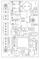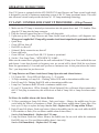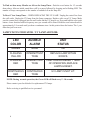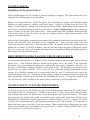
1
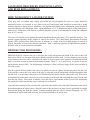
Triton Series
U.V. Disinfection
INSTALLATION & OPERATION MANUAL
This manual covers installation, operation and maintenance
requirements for Neptune U.V. Disinfection Systems.
Model - TRI-8, TRI-12, TRI-20
(During normal operation, the Green LED will flash every 5 - 10 seconds.)
It is important that those responsible for the installation of this
equipment, as well as the owner / operator, read this manual
and carefully follow the instructions and guidelines.
Water Treatment & Accessories, LLC
2045 Rockvale Road
Lancaster, PA 17062
ph: (717) 295 - 9339
fax: (717) 396 - 0364
Revised: 05/12
SAFETY INSTRUCTIONS
WARNING - to guard against injury, basic safety precautions should be observed,
including the following:
1. READ AND FOLLOW ALL SAFETY INSTRUCTIONS.
2. DANGER - To avoid possible electric shock, special care should be taken since water is present
near electrical equipment. Unless a situation is encountered that is explicitly addressed by the
provided maintenance and troubleshooting sections, do not attempt repairs yourself, refer to an
authorized service facility.
3. Carefully examine the disinfection system after installation. It should not be plugged in if there
is water on parts not intended to be wet.
4. Do not operate the disinfection system if it has a damaged power cord or plug, if it is malfunctioning or if it is dropped or damaged in any manner.
5. Always disconnect water flow and unplug the disinfection system before performing cleaning
or maintenance activities. Never yank the power cord to remove it from an outlet. Grasp the
plug and pull to disconnect.
6. Do not use this disinfection system for other than the intended use (potable water applications.)
The use of attachments not approved, recommended or sold by the manufacturer / distributor
may cause an unsafe condition.
7. Intended for indoor use. Do not install this disinfection system where it will be exposed to the
weather. Do not store this disinfection system where it will be exposed to temperatures below
freezing unless all the water has been drained from it and the water supply has been disconnected.
8. Read and observe all the important notices and warnings on the water disinfection system.
9. If an extension cord is necessary, a cord with a proper rating should be used. A cord rated for
less Amperes or Watts than the disinfection system rating may over heat. Care should be taken
to arrange the cord so that it will not be tripped over or accidentally pulled from the outlet.
1. SAVE THESE INSTRUCTIONS.
WARNING: The light given off by this unit can cause serious burns to unprotected eyes and skin.
Never look directly at a lit UV lamp. When performing any work on the UV Disinfection System,
always unplug the unit first. Never operate the UV system while the lamp is outside of the UV
chamber.
WARNING: The UV lamp inside of the disinfection system is rated at an effective life of approximately 9,000 hours.
To ensure continuous water treatment, replace the UV lamp
annually with the appropriate Aqua Treatment Services UV lamp. Failure to comply may
present a fire hazard.
2
FUNCTION:
The function of this ultraviolet disinfection unit is to provide in excess of 99% reduction of all water
borne pathogenic (disease causing) bacteria.
Model Triton series have a number code designation correspondent to the maximum gpm
(gallons per minute) flow rate of the unit. I.E.- TRI-8 has a maximum flow capacity of 8 gpm.
Applications:
Ultraviolet Germicidal Disinfection
Neptune Ultraviolet Disinfection Units are designed to destroy micro-organisms in water supplies. The
Ultraviolet lamp peak radiation of 254 nanometer wavelength (nm) destroys or inactivates the D.N.A.
(deoxyribonucleic acid) which absorbs the Ultraviolet radiation.
Triton Germicidal
Disinfection units meet minimum dosages of 30,000 microwatt second per square centimeter.
MAXIMUM CONCENTRATION LEVELS BEFORE ULTRAVIOLET:
Turbidity.................................5 NTU
Color.......................................None
Manganese........................0.05 ppm
Hardness..........................................7 gpg
Iron...................................................0.3 ppm
pH....................................................6.5 - 9.5ppm
Important Note - Pre-filtration equipment may be required if these parameters cannot be maintained.
Flow rate must not exceed rated capacity of the unit.
DESCRIPTION OF EQUIPMENT:
The Triton series has an unique design with an ultraviolet germicidal lamp housed within a
single quartz sleeve surrounded by a stainless steel pressure chamber. The chamber is fabricated out
of 304 Stainless Steel.
These units come with an ultraviolet lamp designed with four pins at one end.
The quartz sleeve is intended to be placed through the disinfection chamber and will slightly protrude
through the threaded nipple. The ultraviolet lamp is placed within this quartz sleeve. The U.V. light
shines through this specially designed hard quartz sleeve for maximum disinfection efficiency to meet
the requirements for bacteria reduction in potable water.
The inlet/outlet are located on one side of the chamber and may be interchanged as to designation
dependent upon installation. A Site Port is provided for safe and easy view of operation. A box is
secured to the wall and the chamber is held in place by tightening the lock nut to both mounting
box and chamber.
3
GENERAL CONSIDERATIONS FOR ALL DISINFECTION UNITS:
1.
When installing the equipment, it is necessary that the unit be isolated from vibration,
heavy equipment, and poorly connected piping.
2.
Incoming water temperature to the unit should not exceed 35° minimum to110° maximum
degrees Fahrenheit.
3.
The operating pressure should not exceed 100 psi.
4.
Before putting the unit into final operation follow sanitation procedures as outlined in this
manual for proper disinfection. Sanitizing all discharge piping and fittings with household
bleach from disinfection unit to point of use removes existing contaminants and gives
the unit a “clean start.” Be sure to rinse with U.V. treated water.
5.
A proper flow control must be used to insure only the designated flow through the unit.
GENERAL PRECAUTIONS TO BE FOLLOWED AT ALL TIMES:
1.
Always disconnect electrical power to any U.V. unit before servicing.
2.
Under no circumstances should personnel look at a U.V. lamp in operation
(EXCEPT through an external Site Port lens located on the outside of the unit).
3.
U.V. disinfection units must always be properly grounded.
INSTALLATION:
The Triton series are always placed after the pressure tank and any other type of treatment devices (i.e.
softeners, filters).
These units are normally installed in a vertical position in an enclosed area with good ventilation. Allow
clearance of at least the unit’s length at one end for quartz sleeve and bulb replacement. Two (2) anchor
bolt holes are provided for proper wall support. Use wall plugs with screws for sufficient support
(not included). A lock nut secures the mounting box to the U.V. chamber.
If your piping system is subject to impulse pressure resulting in a “water hammer” condition, a surge
tank or other means must be provided to remove this condition; otherwise, this extreme shock pressure
condition may rupture or fracture the quartz sleeve.
Make all plumbing connections to allow for ease of service. Be sure to follow all local plumbing codes
and U.V. restriction requirements where specified by local authorities.
The electrical control box is vented to allow proper air ventilation to components. For outdoor applications install a protective rain guard shield (contact your UV supplier for part number) to prevent water
from direct contact with the control box. The rain guard is not necessary for indoor applications.
4
STEP BY STEP INSTALLATION:
1. Turn off the water before cutting into the water line.
2. Assess the installation (i.e. type of pipe, size of lines, etc.) and obtain necessary plumbing
fittings for installation. Inlets and outlets on 8 gpm units are 3/4" MNPT. Use Teflon tape
on all threaded connections and avoid over tightening.
Note: The flow control is a press in type. Each unit has a 3/4" MNPT inlet/outlet machined so
the press in flow control can be easily inserted into whichever port you select for the
inlet. Make sure the rubber part of the flow control is facing outward from the port
selected. Simply hand press or slightly tap in the flow control until it sits on the
inside ledge of the machined port.
3. Using the mounting box provided, secure unit to wall, or other surface. Make sure to
allow enough room to install, replace, and clean the quartz sleeve and bulb. Installing a
water shut-off valve before and after the unit is recommended to make servicing easy.
4. After mounting, install quartz sleeve, O-Ring, and bulb per instructions. Turn on the water
slowly, check for leaks, and repair as needed prior to full service operation.
5. After the unit is full of water, plug it into a grounded 110V outlet. Observe operation
through the safety Site Port. The lamp will show a bright blue glow. If any problems
are noted, consult trouble shooting guide.
GENERAL INSTALLATION DIAGRAM
5
WTA-280CB
6
OPERATING INSTRUCTIONS
Your UV System is equipped with the ATS-280CB UV Lamp Detector and Timer circuit board which
is designed to provide a continuous monitoring system of the UV lamp operational status. This solid
state electronic circuit board provides the latest in UV lamp monitoring technology.
UV LAMP / CONTROL BOX START UP PROCEDURE - (4 Step Process)
1. Make sure the UV lamp is inserted per instructions into the quartz sleeve and UV chamber. Then
plug the UV lamp into the lamp connector.
2. Plug the electrical control box into a 120volt wall plug outlet.
3. Upon start up the UV lamp Detector and Timer circuit board will perform a self diagnostic test.
When power is applied the UV lamp will go on and a circuit board output check is performed as follows:
• Quick Beep
• Green LED on, then off
• Red LED on, then off
• Solenoid / Relay connection on, then off
• Pause with beeps
• Green LED on = System Check OK, UV System is operational.
4. Set the 1 Year Lamp Timer – WITH NEW UV LAMP –
Make sure the control box is plugged into the wall outlet and the UV lamp is on. Press and hold the reset
push button. A tone that descends in frequency once per second will be heard. Hold the reset button
down for approximately 5-8 seconds until you hear a continuous tone. At this point release the button.
The 1 year lamp timer has just been reset.
UV lamp Detector and Timer circuit board Lamp Operation and Alarm features:
• UV System OK – Green LED will flash every 5 - 10 seconds.
• 30 Days remaining on Lamp Life – Flashing Yellow LED with an intermittent audible tone.
• End of Lamp Life- Flashing Red LED with an intermittent audible tone.
• Lamp Out- Continuous Red LED with a continuous audible tone.
• If your UV System has a 120Vac Normally Closed Solenoid Valve or Remote Alarm connected to
the UV Unit plug-in connection, this will activate at End of Lamp Life or Lamp Out alarm conditions.
To Silence the Audible Alarm with Snooze Button:
1. 30 Days remaining on Lamp Life Alarm - Push reset button – Silences the audible tone for two
weeks while the Yellow Led continues to Flash. (You can Silence audible alarm 2 times Max.) You
have up to 30 days to replace the lamp. Service Unit - Replace the UV Lamp within 30 Days.
2. End of Lamp Life Alarm - Push reset button- Silences the audible tone for one week while the RED
LED continues to flash. (You can Silence audible alarm 4 times Max.)
Service Unit Immediately - Replace the UV Lamp.
3. Lamp Out Alarm- Push reset button- Silences the audible tone for one week while the continuous
Red LED stays on. (You can Silence audible alarm 1 time only.)
Service Unit Immediately - Replace the UV Lamp.
7
To Find out how many Months are left on the Lamp Timer - Push the reset button for 1-2 seconds
then release. After an initial sound there will be a pause followed by beeping and a flashing LED. The
number of beeps corresponds to the number of months left on the lamp life.
To Reset 1 Year Lamp Timer – WHEN REPLACING THE UV LAMP. Unplug the control box from
the wall outlet. Unplug the UV lamp from the Lamp connector. Replace with a new UV Lamp. Make
sure the control box is plugged into the wall outlet and the UV lamp is on. Press and hold the reset push
button. A tone that descends in frequency once per second will be heard. Hold the reset button down for
approximately 5-8 seconds until you hear a continuous tone. At this point release the button. The 1 year
timer has just been reset.
LAMP STATUS INDICATOR / UV LAMP ADVISOR:
LED
COLOR
AUDIBLE
ALARM
UNIT
STATUS
GREEN
NONE
OK
FLASHING
YELLOW
INTERMITTENT
TONE
REPLACE LAMP WITHIN
30 DAYS.
FLASHING
RED
INTERMITTENT
TONE
LAMP HAS EXCEEDED 1 YEAR
OF OPERATION, REPLACE
LAMPS & RESET.
CONTINUOUS
RED
CONTINUOUS
TONE
UV LAMP IS NOT LIT.
NOTE: During normal operation, the Green LED will flash every 5 - 10 seconds.
Please contact your local dealer for replacement UV lamps.
Refer servicing to qualified service personnel.
8
QUARTZ SLEEVE:
Installation of the Quartz Sleeve:
Always handle quartz sleeves carefully to prevent breaking or chipping. The quartz sleeves are to be
clean and free of fingerprints before installing.
Remove the compression nut. Install the quartz sleeve through the stainless steel threaded nipple
allowing an equal amount to extend beyond each nipple. Install the O-Ring down the top of the
nipple. Avoid riding the O-Ring on any threaded part of the nipple. Hand-tighten each compression
nut to form a compression seal around the quartz sleeve. Avoid overtightening the nuts, which may
cause a fracture on the end of the quartz sleeve. Under normal operation conditions, hand-tightening
will provide a 100 psi seal. Do not use any devices to tighten end nuts. Repeat this procedure at the
opposite end of the chamber.
After you have tightened the compression nut and all other plumbing connections, open the outlet valve.
Slowly open the inlet valve and flush out all remaining air. Then close the outlet valve and
slowly open the inlet valve fully. Check the unit for leaks. If you find a leak at the compression nut,
tighten the nut further. If the leak continues, drain the unit and inspect the quartz O-Ring and quartz
sleeve for proper seal. Once you complete checking the unit, reassemble O-Ring and tighten gland nut.
Repressurize the unit and check again.
REQUIREMENTS FOR CLEANING THE QUARTZ SLEEVE:
As water passes through the U.V., minerals, debris and other matter in the water may deposit onto the
quartz sleeve. After sufficient film has formed on the quartz sleeve, the ability of the ultraviolet
germicidal rays to pass though the quartz sleeve and into the water may be impaired. Therefore, it is
necessary to determine a cleaning schedule for the quartz sleeve. The frequency will depend on the
specific type of water conditions. If the water has been processed through deionization, reverse
osmosis, or is distilled, cleaning may be required only once per year. If untreated water is used, the
cleaning frequency will vary. A minimum of once yearly is standard recommendation for cleaning and
lamp replacement. Contact your local dealer for scheduling this service. Your specific situation will
vary the frequency time according to the water quality of the home or facility application.
QUARTZ SLEEVE CLEANING PROCEDURES:
To clean the quartz sleeve, turn off the water flow to the disinfection unit, turn power off, and disconnect
the electrical service to the lamp pins. Carefully remove the U.V. lamp. Loosen the compression nuts
with O-Rings and remove the quartz sleeve while draining the water from the chamber. The quartz
sleeve may then be washed with a mild soap and hot water solution and rinsed clean with hot water.
Should this be insufficient to clean the quartz sleeve, a mild acid may be used (i.e. vinegar). Be certain
to follow all recommended safety and handling procedures on the acid container. It is important to
handle the quartz sleeve with care to prevent breakage. Make certain that all finger prints are wiped
clean before reinstalling (see installation of the quartz sleeve). Replace O-Rings [ATS8-544(1)] every
time a quartz sleeve is cleaned or replaced.
9
U.V. LAMPS:
INSTALLATION OF THE ULTRAVIOLET LAMPS:
**DO NOT PUT POWER ON AT THIS TIME!**
CAUTION: Never look directly at a operating U.V. lamp operate a U.V. lamp outside the
disinfection chamber.
Make sure unit is unplugged when installing or servicing ultraviolet lamp. Remove any paper tabs on
the U.V. lamp and avoid allowing fingerprints and other debris to deposit. Carefully place the bulb
inside the quartz sleeve leaving enough space to connect the socket connector to the lamp pins. Insert
the protective polyurethane endcaps into the quartz open ends to secure the lamp(s) in place or reinstall
brass dust covers.
ULTRAVIOLET LAMP MAINTENANCE REQUIREMENTS:
The U.V. lamp is rated for 9,000 hours of continuous use. After this period of time, the U.V. lamp has
undergone a photochemical change. While the lamp will not normally be burned out, the lamp quartz
may no longer emit the 254-nm shortwave U.V. to effectively kill bacteria. Failure to replace the U.V.
lamps every 9,000 hours may cause bacteriological breakthrough. Should the use of the disinfection
unit be intermittent, in no case should the U.V. lamp be used for more than 24 months regardless of the
number of hours of operation due to normal shelf life degradation of the U.V. bulb. Changing the quartz
sleeve should be done at the same time U.V. lamp replacement is scheduled.
It is recommended that your water supply be tested periodically (yearly) through your local health
department or approved certified laboratory.
ELECTRICAL:
The Triton series are furnished with 6' line cord that will plug into a 110V outlet. Electrical receptacles
must be properly grounded for safe operation. Improper grounding will void any warranty.
When possible use a separate breaker to minimize voltage fluctuations and avoid accidental shut off.
After unit is installed and water is turned on, plug the unit into 110V wall receptacle. View lamp
operation through safety Site Port lens. NOTE: Avoid exposing your eyes to U.V. light.
10
SANITATION PROCEDURE FOR INSTALLATION
AND BULB REPLACEMENT:
HOW TO DISINFECT A WATER SYSTEM:
Every new well, or existing water supply system that has been disrupted for service or repair, should be
disinfected before it is returned to use. Water in the well and storage tank should be treated with a strong
chlorine solution to destroy disease organisms. All pipelines and fixtures in the distribution system should be
rinsed and flushed with chlorinated water. Upon installation of a U.V. disinfection unit or yearly bulb replacement service, disinfection with chlorine to initially flush the system is recommended to assure line sanitation
prior to U.V. start up.
The source of chlorine can be ordinary household liquid laundry bleach (about 5.25% available chlorine). The
quantity required depends on the volume of water to be treated. The United States Environment Protection
Agency (EPA) indicated that about 100 parts of chlorine, by weight, mixed in a million parts of water will
destroy essentially all water-borne disease organisms. Table 1 shows the quantity of liquid bleach required to
disinfect wells of various diameters and depths.
DISINFECTION PROCEDURE:
DRILLED WELLS: Remove the cap or seal form the casing and measure the depth of the water in the well,
then refer to Table 1 to determine how much chlorine solution should be used. In some instances removing the
seal to measure the water can be a difficult task, and it is easier to guess at the quantity of disinfectant needed
than it is to make a more accurate determination (footnote, Table 1). As a general rule, it is better to use too
much chlorine than too little. The disadvantage in doing so is that it will take longer for the taste and odor to
leave the system.
Mix the required chlorine disinfectant with a few gallons of water in a plastic bucket and pour it into the well.
If the seal has a removable vent, unscrew the pipe or plug and pour the disinfecting solution through the hole
into the well. For maximum effectiveness, the chlorine must be mixed with the water in the well. This can be
accomplished by connection a hose to a faucet beyond the pressure tank, and circulating the water from the tank
back into the casing. After about 20 minutes, close this faucet, open another at the far end of the distribution
line and let the water run until the odor of chlorine can be detected.
Close this faucet and repeat the procedure for each of the other outlets on the line until chlorinated water can be
detected throughout the entire system. Keep this water in the pipeline for at least 6 hours, (preferably overnight)
then start the pump and flush the system. Continue pumping until the odor of chlorine disappears. For U.V.
installations or replacement bulb servicing, this can be shortened to 20 minute time.
11
LARGE DIAMETER WELLS: Dug or bored wells should be disinfected in the same way as a drilled
one. Lower the water level as much as possible, remove the sand, silt and debris, and then treat with the chlorine
solution. Mix thoroughly by circulating the water back into the well and use the hose to rinse the interior
lining of the well. Do not try to disinfect an unprotected, unlined well because new seepage or surface
contamination will flow into the water about as fast as you can disinfect it. Disinfect the pipeline distribution
system as indicated for drilled wells.
SPRINGS AND CISTERNS: Mix about ½ cup of household bleach in 5 gallons of water and use this to
scrub the walls of the spring box or holding tank. With a constant flow of fresh water from the spring, there is
probably no way of detaining the chlorine solution in the reservoir for more than a few minutes. However, the
chlorinated water should flow through the pipeline to disinfect the distribution system. Cisterns can be disinfected in the same way but a source of clean water will be needed to flush the dirty waste out of the system.
For additional information about how to protect wells and springs and keep them from becoming contaminated,
call or visit your local Cooperative Extension office, or your nearest certified water treatment specialist.
TABLE 1 ** Quantity of solution mixed - 5.25% available chlorine (laundry bleach) for disinfecting
wells, or 52,500 P.P.M..
WQA recommends 50mg/l or ppm chlorine concentration.
C2 X V2 / C1 = V1
Formula -
C1= Household Bleach (52,500 P.P.M.)
V1= Chlorine Amount Needed
C2= 50 mg/L
V2= 80 gallons holding time
I.E. 50-ml/g X 80 gal= 4000/52,500= .08 gallons of chlorine (5.25%)
.08 gal chlorine (5.35%) X 128 (oz/gal) = 10.24 oz (5.25%)
Dug Wells - 3 to 4 feet diameter - 4 cups per foot of water
Drilled Wells - 3 to 8 inch diameter - 1 cup per foot of water
TOO MUCH CHLORINE IS BETTER THAN TOO LITTLE:
**
In situations where it is inconvenient to determine depth of water or diameter of a drilled well, a
minimum of 1/2 gallon of household bleach may be used for wells up to 8 inches in diameter with estimated to
be less than 80 feet deep; 1 gallon should be used for similar size wells with water deeper than 80 feet. In case
of a well yielding more than 50 gallons per minute, special procedures are required. Seek the advice of a
certified water treatment specialist.
Wait a day or two before you have another sample tested. Do not take a sample for testing if the odor of
chlorine is still present in water.
12
REMEMBER - To make your water supply safe:
- Locate your well properly.
- Protect it from surface contamination.
- Test water periodically for coliform bacteria. (Home-yearly, Farm-2X yearly)
- Chlorinate, or filter and disinfect the water if necessary.
When installing an ultraviolet disinfection system, a prefilter with sump may serve as a source to
sanitize the water lines only. For whole system disinfection follow procedure as outlined above.
Source: The Pennsylvania State University College of Agriculture Cooperative Extension.
How to Sanitize a Water System Using Well Sanitizer Pellets
Table 1
Well Diameter Inches
2
3
4
5
6
8
10
12
24
36
Weight of Pellets lbs. - oz.
0 - 1.5
0 - 3.0
0 - 6.0
0 - 8.0
0 - 12.0
1 - 5.0
2-0
3-0
12 - 0
26 - 0
Cups of Pellets
1/4
2/5
3/4
1
1-1/2
2-1/2
4
6
24
---
Number of Pellets
40
80
140
200
300
500
800
----------
* To produce a 400 P.P.M. chlorine dosage
NOTE:
Pellets Weight = 1.14 gram each, 25 pellets/oz., 400 pellets/lb.
1 cup of pellets = 1/2 lb., or 200 pellets, or 8 oz.
To produce a 400 P.P.M. chlorine concentration, to sanitize a water system, use one-half (1/2) pound chlorination
pellets for each 100 gallons of water in the system (1/2 lb/100 gal= 8 oz/100 gal= 200 pellets/ 100 gal= 1 cup
pellets/100 gal). Table 1 shows how many pellets too use per 100 feet of water in various diameter wells.
13
DRILLED WELLS:
1. Remove the cap or seal from the casing and measure the depth of the water in the well, then refer to
Table 1 to determine how many chlorine pellets should be used. In some instances removing the seal
to measure the water can be a difficult task, and it is easier to estimate well and water depth from well
log or other records.
2. Remove well cap and determine if there is an unobstructed path from the top of the well to the
water level. If it is not possible to remove the well cap, remove vent or sanitation access plug.
3. Drop one pellet into the well and listen to hear if it hits the water. If the pellet hits the water, drop
one-half the number of pellets determined to be needed into the well. These will sink to the bottom
and sanitize the lower part of the well.
4. Mix the remaining pellets in a few gallons of water in a CLEAN plastic container and pour the
solution into the well.
5. In order to mix the chlorine thoroughly throughout the entire water system, it is necessary to
recirculate the water in the well. This can be accomplished by connection a hose to an out side faucet
that is located after the pressure tank. Use hose to run water back down the well (this also rinses upper
portion of well). After about 15 minutes of recirculation the water, a strong chlorine odor should be
apparent. Turn off hose.
6. Bypass water softener and filters and open each water outlet in the water system until chlorine is
present in water. This procedure assures that all the water in the system is chlorinated.
7. Allow the chlorinated water to stand in the system for at least one (1) hour, and preferable overnight.
After this, open an outside faucet system until water runs chlorine free. Repeat flush operation on each
faucet in system.
NOTE:
A. Chlorine may break loose iron deposits, slime and organic material. This material will make
the water run colored. The material broken loose may plug pump screens. Do not continue to
run pump if water doesn’t flow.
B. The high level of chlorine required to sanitize a water system is corrosive to most metals and
chlorine solution must not be allowed to remain in water system more than 36 hours before
being completely flushed from system.
8. After system has been completely flushed, perform a bacteriological analysis on the water
following all applicable procedures.
NOTE:
Always follow the sanitizing procedure required by applicable state or local laws.
EPA Registered: Well sanitizer pellets are EPA Registered for sanitizing potable water. EPA Registration
No. 50510-1
14
TROUBLESHOOTING GUIDE
PROBLEM
U.V. lamp will not light
Leak at quartz nipple
CAUSE
CORRECTION
Check input voltage if below
or above 120 volts
Install a voltage regulator
Line cord disconnected
or outlet defective
Check, replace
Defective U.V. lamp
Replace
Defective lamp ballast
Check output voltage
Replace ballast
Loose open-circuit wire
Trace out and repair
Defective or cracked O-Ring
Replace O-Ring
O-Ring not seated properly
Replace O-Ring
15
LIMITED WARRANTY
All parts of the disinfection unit, with the exception of the U.V. lamp, are guaranteed for
one (1) year against defective parts and workmanship. The stainless steel disinfection
chamber on the Triton series is guaranteed for ten (10) years.
Any
component which fails to operate satisfactorily within their time period will be replaced
free of charge under the following conditions:
NOTIFY YOUR LOCAL DEALER OR DISTRIBUTOR OF ANY PARTS
SUSPECTED OF BEING DEFECTIVE.
Upon approval by Neptune U.V. Disinfection Systems, the Dealer/Distributor should return the
item to Water Treatment & Accessories, LLC 2045 Rockvale Road, Lancaster, PA 17062 (prepaid).
If a part proves to be defective, it will be repaired or replaced and returned to the
Dealer/Distributor freight paid.
It is the dealer/customer responsibility to reinstall any components which require
replacement under warranty. No labor will be covered under this Limited Warranty.
Neptune U.V. Disinfection Systems’ or sellers liability is limited to the repair or replacement of any
component found to be defective, and in no case shall we be held liable for damage, either
immediate or subsequent, arising out of the use of this equipment.
Neptune®, is the registered trademark of Water Treatment & Accessories, LLC, the
manufacturer of Neptune UV brand UV systems, which include the Neptune/"Triton" series.
Only parts sold through authorized dealers (or Water Treatment & Accessories, LLC, if there
is no dealer in your area), are subject to warranty by Water Treatment & Accessories, LLC.
Although lamps and other components purchased from other companies may be "compatible"
with the Neptune® and Neptune/Triton systems, we cannot warranty any system or parts if
non-genuine OEM components are used.
16
TRITON SPECIFICATIONS
Model #
Max. Flow
No. Lamps
GPM
KW @
AMP @
120V
120V
Pipe Size
Overall Dimensions
Shipping
LxWxD
Weight
TRI-8
8
1
0.03
0.25
3/4'' MIP
21'' x 3.5'' x 3.5''
9 Lbs.
TRI-12
12
1
0.03
0.25
3/4'' MIP
32'' x 3.5'' x 3.5''
18 Lbs.
TRI-20
20
1
0.03
0.25
1'' MIP
35'' x 5'' x 5''
21 Lbs.
17
SUGGESTED PROCEDURE FOR OBTAINING STERILE WATER SAMPLES:
Prior to taking the water sample, be sure to have on hand an adequate supply of sterile bottles. These
sterile bottles should be obtained from a reputable laboratory and should have been autoclaved and
contained within a plastic outer wrapping.
1.
Prior to taking the sample, it is imperative that the sample cock, faucets, etc. be opened
at full force for a complete three and one half minutes.
2.
After the valve has been left wide open for three and one half minutes, reduce the flow
to a reasonable stream of water. Flow to drain an additional three minutes.
3.
Open the sterile bottle or sterile container being used. Holding the cap in a down
position, the operator should then hold his breath while taking the sample so as to
avoid oral contamination of the sample. The operator must not allow his finger to
touch the inside of the cap or the neck of the bottle.
4.
After the sample has been taken, the cap should immediately be tightly placed on the
sample container.
5.
The sample container should be placed in a plastic wrapping and should be taken to
the laboratory for plating as soon as possible following the above procedure.
We recommend duplicate samples be taken at each test station during each specific test so as to avoid
loss of sample through laboratory error and to insure reasonable validity through comparison.
Check with your local laboratory to assure proper sampling and submittal procedure.
18
WIRING DIAGRAM
19
20
DRAWING AND PART NUMBERS
21
TRI-8 Explosion
22
TRI-8 Parts List
CODE
PART#
DESCRIPTION
QTY.
1
WTA-5249
Chamber
1
2
WTA-R01
¾” Flo.-Et. Retainer 8 gpm
1
3
WTA-F08
8 gpm Flo.-Et.
1
4
WTA-5173
Site Port O-Ring
1
5
WTA-5172
Site Port Lens
1
6
WTA-5171
Site Port Nut
1
7
WTA-268
Top Mounting Bracket
1
8
WTA5-410
Lock Nut
1
9
WTA8-544
End Nut O-Ring (seal quartz sleeve) 1
10
WTA5-409
Brass End Nut
1
11
WTA8-546
O-Ring (for shroud on end nut)
1
12
WTA-7091
Gaynor Connector
1
13
HS4-075-BK Shrink Tubing
.167
14
WTA-N1155 Brass Shroud
1
15
9600K31
Grommet
1
16
9936K18
Cable
1.5
17
WTA-264
Box Bottom
1
18
WTA-A115
Stand-offs
3
19
WTA-6L3
Strain Relief
1
20
WTA-4000
Power Cord
1
21
WTA-6L1
Strain Relief
1
22
WTA-262
Ballast Plate
1
23
WTA1-420
Ballast 120V/60Hz
1
24
WTA-7600
Plastic Sight Lens (for cover)
1
25
WTA-263
Box Top
1
26
WTA-280CB Lamp Indicator Circuit Board
1
27
94662A530
Circuit Board Stand-offs
3
28 562-738W-CX2-01 Outlet Plug
1
29
95495K11
Rubber Bumper
1
30
WTA-269
Bottom Mounting Bracket
1
31
WTA-476D
Quartz Sleeve
1
32
WTA4-450
Bulb
1
23
TRI-12 Explosion
24
TRI-12 Parts List
CODE
PART#
DESCRIPTION
QTY.
1
WTA-5252
Chamber
1
2
WTA-R02
¾” Flo.-Et. Retainer 12 gpm
1
3
WTA-F12
12 gpm Flo.-Et.
1
4
WTA-5173
Site Port O-Ring
1
5
WTA-5172
Site Port Lens
1
6
WTA-5171
Site Port Nut
1
7
WTA-268
Top Mounting Bracket
1
8
WTA5-410
Lock Nut
1
9
WTA8-544
End Nut O-Ring (seal quartz sleeve) 1
10
WTA5-409
Brass End Nut
1
11
WTA8-546
O-Ring (for shroud on end nut)
1
12
WTA-7091
Gaynor Connector
1
13
HS4-075-BK Shrink Tubing
.167
14
WTA-N1155 Brass Shroud
1
15
9600K31
Grommet
1
16
9936K18
Cable
1.5
17
WTA-267
Box Bottom
1
18
WTA-A115
Stand-offs
3
19
WTA-6L3
Strain Relief
1
20
WTA-4000
Power Cord
1
21
WTA-6L1
Strain Relief
1
22
WTA-265
Ballast Plate
1
23
WTA1-421
Ballast 120V/60Hz
1
24
WTA-7600
Plastic Sight Lens (for cover)
1
25
WTA-266
Box Top
1
26
WTA-280CB Lamp Indicator Circuit Board
1
27
94662A530
Circuit Board Stand-offs
3
28 562-738W-CX2-01 Outlet Plug
1
29
95495K11
Rubber Bumper
1
30
WTA-269
Bottom Mounting Bracket
1
31
WTA-759D
Quartz Sleeve
1
32
WTA4-739
Bulb
1
25
TRI-20 Explosion
26
TRI-20 Parts List
CODE
PART#
DESCRIPTION
QTY.
1
WTA-5266
Chamber
1
2
WTA-5173
Site Port O-Ring
1
3
WTA-5172
Site Port Lens
1
4
WTA-5171
Site Port Nut
1
5
WTA-270
Top Mounting Bracket
1
6
WTA5-410
Lock Nut
1
7
WTA8-544
End Nut O-Ring (seal quartz sleeve) 1
8
WTA5-409
Brass End Nut
1
9
WTA8-546
O-Ring (for shroud on end nut)
1
10
WTA-7091
Gaynor Connector
1
11
HS4-075-BK Shrink Tubing
.167
12
WTA-N1155 Brass Shroud
1
13
9600K31
Grommet
1
14
9936K18
Cable
1.5
15
WTA-267
Box Bottom
1
16
WTA-A115
Stand-offs
3
17
WTA-6L3
Strain Relief
1
18
WTA-4000
Power Cord
1
19
WTA-6L1
Strain Relief
1
20
WTA-265
Ballast Plate
1
21
WTA1-421
Ballast 120V/60Hz
1
22
WTA-7600
Plastic Sight Lens (for cover)
1
23
WTA-266
Box Top
1
24
WTA-280CB Lamp Indicator Circuit Board
1
25
94662A530
Circuit Board Stand-offs
3
26 562-738W-CX2-01 Outlet Plug
1
27
95495K11
Rubber Bumper
1
28
WTA-271
Bottom Mounting Bracket
1
29
WTA-832D
Quartz Sleeve
1
30
WTA4-810
Bulb
1
31
V7A106D-20 20 gpm Flow Control
1
27