1
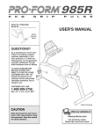
Model No. PFCCEX34390
Serial No.
USER'S MANUAL
Serial
Number
Decal
QUESTIONS?
As a manufacturer, we are committed to providing complete
customer satisfaction. If you
have questions, or if there are
missing parts, we will guarantee
complete satisfaction through
direct assistance from our factory.
TO AVOID UNNECESSARY
DELAYS, PLEASE CALL
DIRECT TO OUR TOLL-FREE
CUSTOMER HOT LINE. The
trained technicians on our
customer hot line will provide
immediate assistance, free of
charge to you.
CUSTOMER HOT LINE:
1-888-936-4266
Mon.–Fri., 8 a.m.–6:30 p.m.
Eastern Standard Time
Patent Pending
CAUTION
Read all precautions and instructions in this manual before using
this equipment. Keep this manual
for future reference.
Visit our website at
www.proform.com
new products, prizes,
fitness tips, and much more!
TABLE OF CONTENTS
IMPORTANT PRECAUTIONS . . . . . . . . . . . . . . . . . . . . . . . . . . . . . . . . . . . . . . . . . . . . . . . . . . . . . . . . . . . . .3
BEFORE YOU BEGIN . . . . . . . . . . . . . . . . . . . . . . . . . . . . . . . . . . . . . . . . . . . . . . . . . . . . . . . . . . . . . . . . . . .4
ASSEMBLY . . . . . . . . . . . . . . . . . . . . . . . . . . . . . . . . . . . . . . . . . . . . . . . . . . . . . . . . . . . . . . . . . . . . . . . . . . .5
HOW TO OPERATE THE RECUMBENT CYCLE . . . . . . . . . . . . . . . . . . . . . . . . . . . . . . . . . . . . . . . . . . . . . . .9
MAINTENANCE AND TROUBLE-SHOOTING . . . . . . . . . . . . . . . . . . . . . . . . . . . . . . . . . . . . . . . . . . . . . . . .12
CONDITIONING GUIDELINES . . . . . . . . . . . . . . . . . . . . . . . . . . . . . . . . . . . . . . . . . . . . . . . . . . . . . . . . . . . .13
CUSTOMER RECORD . . . . . . . . . . . . . . . . . . . . . . . . . . . . . . . . . . . . . . . . . . . . . . . . . . . . . . . . . . . . . . . . .14
HOW TO ORDER REPLACEMENT PARTS . . . . . . . . . . . . . . . . . . . . . . . . . . . . . . . . . . . . . . . . . . . . . . . . . .15
LIMITED WARRANTY . . . . . . . . . . . . . . . . . . . . . . . . . . . . . . . . . . . . . . . . . . . . . . . . . . . . . . . . . . .Back Cover
Note: An EXPLODED DRAWING and a PART LIST are attached in the centre of this manual. Save the
EXPLODED DRAWING and PART LIST for future reference.
2
IMPORTANT PRECAUTIONS
WARNING:
To reduce the risk of serious injury, read the following important precautions before using the recumbent cycle.
1. Read all instructions in this manual before
using the recumbent cycle.
7. The cycle should not be used by persons
weighing more than 250 pounds (115 kg).
2. It is the responsibility of the owner to ensure
that all users of the recumbent cycle are adequately informed of all precautions. Use the
recumbent cycle only as described in this
manual.
8. Always keep your back straight when using
the recumbent cycle; do not arch your back.
3. Use the recumbent cycle indoors on a level
surface. Keep the recumbent cycle away from
moisture and dust. Place a mat under the
recumbent cycle to protect the floor.
10. The recumbent cycle does not have a freewheel; the pedals will continue to move until
the flywheel stops.
9. If you feel pain or dizziness while exercising,
stop immediately and cool down.
11. The pulse sensor is not a medical device.
Various factors, including the user's movement, may affect the accuracy of heart rate
readings. The pulse sensor is intended only
as an exercise aid in determining heart rate
trends in general.
4. Inspect and tighten all parts regularly.
Replace any worn parts immediately.
5. Keep children under the age of 12 and pets
away from the recumbent cycle at all times.
6. Wear appropriate clothing when exercising;
do not wear loose clothing that could become
caught on the recumbent cycle. Always wear
athletic shoes when using the recumbent
cycle.
12. The recumbent cycle is intended for home
use only. Do not use the recumbent cycle in
a commercial, rental, or institutional setting.
WARNING:
Before beginning this or any exercise program, consult your physician. This
is especially important for persons over the age of 35 or persons with pre-existing health problems.
Read all instructions before using. ICON assumes no responsibility for personal injury or property
damage sustained by or through the use of this product.
3
BEFORE YOU BEGIN
Department toll-free at 1-888-936-4266, Monday
through Friday, 8 a.m. until 6:30 p.m. Eastern
Standard Time (excluding holidays). To help us assist
you, please mention the product model number and
serial number when calling. The model number is
PFCCEX34390. The serial number can be found on a
decal attached to the recumbent cycle (see the front
cover of this manual).
Congratulations for selecting the new PROFORM®
985R recumbent cycle. Cycling is one of the most
effective exercises for increasing cardiovascular fitness, building endurance, and toning the entire body.
The PROFORM® 985R offers an impressive array of
features to let you enjoy this healthful exercise in the
convenience and privacy of your home.
For your benefit, read this manual carefully before
you use the PROFORM® 985R. If you have questions,
please call our Customer Service
Before reading further, please familiarize yourself with
the parts that are labeled in the drawing below.
Book Holder
Console
Pulse Sensor
Handlebar
Seat
FRONT
Backrest
Pedal Strap
Pedal
Seat Handle
Wheel
BACK
Side Shield
LEFT SIDE
4
ASSEMBLY
Assembly requires two persons. Place all parts of the recumbent cycle in a cleared area and remove the packing materials. Do not dispose of the packing materials until assembly is completed.
Assembly requires the included tools and your own adjustable wrench
driver
.
and Phillips screw-
Use the part drawings below to identify the small parts used in assembly. The number in parenthesis below
each drawing refers to the key number of the part, from the PART LIST in the center of this manual. The second
number refers to the quantity needed for assembly. Note: Some small parts may have been pre-attached for
shipping. If a part is not in the parts bag, check to see if it has been pre-attached.
Ground Screw (82)–1
M6 Nylon Locknut (15)–4
M4 x 16mm
Screw (21)–6
M10 Nylon Locknut (45)–2
M10 x 25mm Button
Head Screw (74)–10
M6 x 38mm Button Bolt (14)–7
M6 Washer (22)–3
M8 Washer (20)–7
M10 Split Washer (17)–10
M8 x 38mm
Button Bolt (24)–4
M10 X 75mm Carriage Bolt (72)–2
M8 x 100mm Button Bolt (63)–3
5
M6 x 22mm
Button Screw (29)–4
1. Attach the Front Stabilizer (2) to the front of the
Frame (1) with two M10 x 75mm Carriage Bolts (72)
and two M10 Nylon Locknuts (45). Make sure that
the Front Stabilizer is turned so the Wheels (75)
are not touching the floor.
1
72
2
75
1
45
2. Slide the Carriage Bar (7) onto the indicated tube on
the Frame (1). Attach the Carriage Bar to the Frame
with four M10 x 25mm Button Screws (74) and four
M10 Split Washers (17).
2
1
17
74
11
17
If the Seat Carriage (11) is not on the Carriage Bar
(7), pivot the Seat Handle (79) to the position shown
and slide the Seat Carriage onto the Carriage Bar.
Move the Seat Carriage to the desired position and
pivot the Seat Handle forward to secure the Seat.
3. Position the Rear Stabilizer (3) under the Carriage
Bar (7) as shown. Attach the Rear Stabilizer to the
Carriage Bar with three M8 x 100mm Button Bolts
(63) and three M8 Washers (20).
17
79
74
17
7
3
63
20
63
20
7
3
6
4. Insert the lower end of the Backrest Frame (8) into
the Seat Frame (27). Attach the Seat Frame and the
Backrest Frame to the Seat Carriage (11) with four
M8 x 38mm Button Bolts (24).
4
24
24
27
8
11
5. Slide a Seat Handle (61) onto one side of the
Backrest Frame (8). Attach the Seat Handle with
two M6 x 38mm Button Bolts (14) and two M6 Nylon
Locknuts (15).
5
8
Attach the other Seat Handle (not shown) to the
other side of the Backrest Frame (8).
15
14
61
6. Attach the Seat (12) to the Seat Frame (27) with
four M6 x 22mm Button Screws (29) and four M8
Washers (20).
6
12
27
20
20
29
7. Attach the Backrest (13) to the Backrest Frame (8)
with three M6 x 38mm Button Bolts (14) and three
M6 Washers (22).
29
7
13
8
22
14
7
8. While another person holds the Upright (6) in the
position shown, connect the Extension Wire (18) to
the Wire Harness (69).
8
Carefully slide the Upright (6) onto the Frame (1).
Be careful to avoid pinching the wires. Loosely
thread four M10 x 25mm Button Screws (74) with
M10 Split Washers (17) into the Upright and the
Frame. Attach the tops of the Side Shields (4, 5)
with two M4 x 16mm Screws (21).
6
17
Front
Firmly tighten the four M10 x 25mm Button Screws
(74) in the following order: front, rear, and then sides.
74
17
1
Rear
18
21
4
69
21
9. While another person holds the Handlebar (16) near
the Upright (6), route the two Pulse Wires (71) into
the Upright and out of the hole at the top of the
Upright.
74
5
9
16
Next, attach the Handlebar (16) to the Upright (6)
with two M10 x 25mm Button Screws (74) and two
M10 Split Washers (17). Make sure that the Pulse
Wires (71) are not pinched between the Handlebar and the Upright.
71
6
17
17
10. Hold the Console (9) near the Upright (6) as shown.
Identify the green console ground wire and attach it
to the Upright with a Ground Screw (82). Make sure
that the console ground wire connector is pointed toward the center of the indicated hole as
shown.
Next, connect the Extension Wire (18) and the two
Pulse Wires (71) to the corresponding wires on the
Console (9). Make sure that the wires are not tangled around each other.
11. Attach the Console (9) to the Upright (6) with the
four M4 x 16mm Screws (21). Make sure that no
wires are pinched between the Console and the
Upright.
74
10
18
Console
Wires
6
71
82
Hole
9
Console
Ground
Wire
11
9
21
6
21
8
12. Identify the Left Pedal (40) (there is an “L” on the
Left Pedal for identification). Using an adjustable
wrench, firmly tighten the Left Pedal counterclockwise into the left arm of the Crank (19). Tighten the
Right Pedal (not shown) clockwise into the right arm
of the Crank. Tighten both Pedals as firmly as
possible. Important: After using the recumbent
cycle for one week, retighten the Pedals. For best
performance, the Pedals must be kept properly
tightened.
Adjust the Left Pedal Strap (41) to the desired position and press the Pedal Strap onto the tab on the
Left Pedal (40). Adjust the Right Pedal Strap (not
shown) in the same way.
12
41
40
Tab
19
13
13. Plug the Power Supply (86) into the jack at the rear
of the recumbent cycle. Note: Your Power Supply
may look different from the one pictured.
86
IMPORTANT: When unplugging the Power
Supply (86), always unplug the Power Supply
from the recumbent cycle first and then from the
wall outlet.
Jack
14. Make sure that all parts are properly tightened before you use the recumbent cycle. Note: After
assembly is completed, some extra parts may be left over. Place a mat beneath the recumbent cycle to protect
the floor.
HOW TO OPERATE THE RECUMBENT CYCLE
HOW TO ADJUST THE POSITION OF THE SEAT
the position shown in the drawing. Next, slide the seat
forward or back to the desired position. To secure the
seat, pivot the seat handle forward.
For effective exercise, the seat
Seat
should be in the
proper position.
As you pedal,
Seat
there should be a
Handle
slight bend in
your knees when
the pedals are in
the farthest position. IMPORTANT: After you
adjust the seat, make sure that your knees will not
touch the handlebar or the console when you
pedal. To adjust the seat, first pivot the seat handle to
HOW TO ADJUST THE PEDAL STRAPS
To adjust the pedal
straps, first pull the
straps off the tabs on
the pedals. Adjust the
straps to the desired
positions and press
the straps back onto
the tabs.
Strap
Tab
9
Program
Profiles
Mode Arrow
Resistance
Buttons
Mode
Button
On/Reset
Button
DESCRIPTION OF THE CONSOLE
Select
Button
HOW TO USE THE MANUAL MODE
The innovative console offers a manual mode and
three preset workout programs. When the manual
mode is selected, the pedaling resistance can be
changed with a touch of a button. When a preset programs is selected, the console will automatically control the pedaling resistance to give you an effective
workout. The console also features seven monitor
modes that provide instant exercise feedback:
1
Plug in the power supply.
Plug the power supply into the recumbent cycle
(see assembly step 13 on page 9). Next, plug the
power supply into an electrical outlet. Note:
When you plug in the power supply, press the
on/reset button, or activate the console by
turning the pedals, the resistance motor will
automatically calibrate itself. During calibration, you will hear the resistance motor turning. Wait until calibration is complete before
continuing.
Speed—When a mode arrow points to this symbol, the console will show your pedaling speed,
in miles per hour.
Time—When a mode arrow points to this symbol, the console will show the elapsed time.
2
Turn on the power.
Press the on/reset button or simply begin pedaling to turn on the power. The entire display will
appear for a moment; the console will then be
ready for use. Note: If the power supply was just
plugged in, the power will already be on.
Distance—When a mode arrow points to this
symbol, the console will show the distance you
have pedaled, in miles.
Fat Calorie—When a mode arrow points to this
symbol, the console will show the approximate
number of fat calories you have burned (see Fat
Burning on page 13).
3
Select the manual mode.
When the power is
turned on, the manual mode will be
selected and the
manual indicator will
light. If a preset program has been
selected, press the
select button repeatedly until the manual
indicator lights.
Calorie—When a mode arrow points to this symbol, the console will show the approximate number of calories you have burned.
Scan—When a mode arrow points to this symbol, the console will show the speed, time, distance, fat calorie, and calorie modes, for 5 seconds each, in a continuous cycle.
Pulse—The pulse window will show your heart
rate when the pulse monitor is used.
10
Manual
Indicator
4
5
Adjust the pedaling resistance as desired.
6
Measure your heart rate, if desired.
As you exercise,
adjust the pedaling
resistance by pressing the resistance buttons. The indicators
on the left side of the
Resistance
console will show
Indicators
which resistance level
is selected. When the
lowest indicator is
dimly lit, resistance
level 1 is selected; when the lowest indicator is
brightly lit, resistance level 2 is selected; when
the second indicator is dimly lit, resistance level 3
is selected; when the second indicator is brightly
lit, resistance level 4 is selected; and so forth.
When the highest indicator is brightly lit, resistance level 10, the most difficult level, is selected.
Note: If the metal contacts on the top and
bottom of the pulse sensor are covered with
clear vinyl strips, peel off the strips before
using the pulse sensor.
Follow your progress with the monitor modes.
When your pulse is
detected, the heartshaped indicator in the
pulse display will flash
each time your heart
beats. A moment later,
your heart rate will be
shown. For the most accurate heart rate reading,
continue to hold the contacts for about 15 seconds.
To measure
your heart rate,
place your
hands on the
metal contacts
on the pulse
sensor. Your
Metal
palms must be
Contacts
resting on the
upper contacts
and your fingers must be touching the lower contacts. Avoid
moving your hands.
The scan mode—To
Mode Arrow
select the scan mode,
repeatedly press the
mode button until an
arrow appears under
the scan symbol.
When the scan mode
is selected, the console will display the
speed, time, distance, fat calorie, and calorie
modes, for 5 seconds each, in a continuous
cycle. A second arrow will show which mode is
currently displayed.
If your heart rate is not shown, make sure that
your hands are positioned as described above.
Be careful not to move your hands excessively or
to squeeze the metal contacts too tightly.
The speed, time, disMode Arrow
tance, fat calorie, or
calorie mode—To
select a single mode
for continuous display,
repeatedly press the
mode button until an
arrow appears by the
desired symbol. Make
sure that there is not an arrow under the scan
symbol.
WARNING:
The pulse sensor is not a medical device. Various factors, including the user’s movement, may
affect the accuracy of heart rate readings. The pulse sensor is intended only
as an exercise aid in determining heart
rate trends in general.
7
The pulse mode—To use the pulse mode, see
step 6.
When you are finished exercising, turn off the
power.
To turn off the power, simply wait for five
minutes. If the pedals are not turned and the
console buttons are not pressed for five minutes,
the power will turn off automatically.
To reset the modes, press the on/reset button.
11
program P2, for example, the profile shows that
the pedaling resistance will gradually increase
during the first ten minutes, and then gradually
decrease during the last ten minutes.
HOW TO USE A PRESET WORKOUT PROGRAM
1
Plug in the power supply.
See step 1 on page 10.
2
4
Turn on the power.
As you exercise, the pedaling resistance will periodically change, as shown by the program profiles on the console. The indicators on the left
side of the console will show the current resistance level. Note: The resistance buttons will not
operate while a preset program is in use.
See step 2 on page 10.
3
Begin your workout.
Select one of the three preset programs.
When the power is
turned on, the manIndicator
ual mode will be
selected and the
manual indicator will
light. To select a
preset program,
press the select button repeatedly until the P1, P2, or P3 indicator
lights. Note: When a preset program is selected,
the resistance motor may calibrate itself and the
displays may reset.
5
Follow your progress with the monitor modes.
See step 5 on page 11.
6
Measure your heart rate, if desired.
See step 6 on page 11.
7
Each preset program will last for approximately
twenty minutes. The program profiles on the right
side of the console show how the pedaling resistance will change during the programs. During
When the preset program is completed, turn
off the power.
To turn off the power, simply wait for five
minutes. If the pedals are not turned and the
console buttons are not pressed for five minutes,
the power will turn off automatically.
MAINTENANCE AND TROUBLE-SHOOTING
Inspect and tighten all parts of the recumbent cycle
regularly. To clean the recumbent cycle, use a soft,
damp cloth. To prevent damage to the console, keep
liquids away from the console and keep the console
out of direct sunlight.
• Do not hold the metal contacts too tightly; doing so
may interfere with heart rate readings.
PULSE SENSOR TROUBLE-SHOOTING
• For optimal performance of the pulse sensor, keep
the metal contacts clean. The contacts can be
cleaned with a soft cloth—never use alcohol,
abrasives, or chemicals.
• For the most accurate heart rate reading, hold the
metal contacts for about 15 seconds.
• Avoid moving your hands while using the pulse sensor. Excessive movement may interfere with heart
rate readings.
12
CONDITIONING GUIDELINES
The following guidelines will help you to plan your
exercise program. Remember that proper nutrition
and adequate rest are essential for successful results.
Fat Burning
To burn fat effectively, you must exercise at a relatively low intensity level for a sustained period of time.
During the first few minutes of exercise, your body
uses easily accessible carbohydrate calories for energy. Only after the first few minutes of exercise does
your body begin to use stored fat calories for energy.
If your goal is to burn fat, adjust the intensity of your
exercise until your heart rate is near the lowest number in your training zone as you exercise. For maximum fat burning, adjust the intensity of your exercise
until your heart rate is near the middle number in your
training zone as you exercise.
WARNING:
Before beginning
this or any exercise program, consult your
physician. This is especially important for
persons over the age of 35 or persons with
pre-existing health problems.
The pulse sensor is not a medical device.
Various factors may affect the accuracy of
heart rate readings. The pulse sensor is
intended only as an exercise aid in determining heart rate trends in general.
Aerobic Exercise
If your goal is to strengthen your cardiovascular system, your exercise must be “aerobic.” Aerobic exercise is activity that requires large amounts of oxygen
for prolonged periods of time. This increases the
demand on the heart to pump blood to the muscles,
and on the lungs to oxygenate the blood. For aerobic
exercise, adjust the intensity of your exercise until
your heart rate is near the highest number in your
training zone.
EXERCISE INTENSITY
Whether your goal is to burn fat or to strengthen your
cardiovascular system, the key to achieving the
desired results is to exercise with the proper intensity.
The proper intensity level can be found by using your
heart rate as a guide. The chart below shows recommended heart rates for fat burning, maximum fat
burning, and cardiovascular (aerobic) exercise.
WORKOUT GUIDELINES
Each workout should include the following three parts:
A warm-up, consisting of 5 to 10 minutes of stretching
and light exercise.A proper warm-up increases your
body temperature, heart rate, and circulation in preparation for exercise.
Training zone exercise, consisting of 20 to 30 minutes of exercising with your heart rate in your training
zone. (During the first few weeks of your exercise program, do not keep your heart rate in your training
zone for longer than 20 minutes.)
To find the proper heart rate for you, first find your age
on the bottom line of the chart (ages are rounded off
to the nearest ten years). Next, find the three numbers
above your age. The three numbers are your “training
zone.” The lowest number is the recommended heart
rate for fat burning; the middle number is the recommended heart rate for maximum fat burning; the highest number is the recommended heart rate for aerobic
exercise.
A cool-down, with 5 to 10 minutes of stretching. This
will increase the flexibility of your muscles and will
help to prevent post-exercise problems.
EXERCISE FREQUENCY
To maintain or improve your condition, plan three workouts each week, with at least one day of rest between
workouts. After a few months of regular exercise, you
may complete up to five workouts each week, if
desired. Remember, the key to success is make exercise a regular and enjoyable part of your everyday
life.
To measure your heart rate, first exercise for at least
four minutes. Then, stop pedaling and measure your
heart rate using the pulse sensor (see step 6 on page
11).
13
CUSTOMER RECORD
Model No.:
Serial No.:
Retailer Name:
Purchase Date:
Retailer Address:
14
HOW TO ORDER REPLACEMENT PARTS
To order replacement parts, call our Customer Service Department toll-free at 1-888-936-4266, Monday through
Friday, 8 a.m. until 6:30 p.m. Eastern Standard Time (excluding holidays). To help us assist you, please be prepared to give the following information when calling:
• The MODEL NUMBER of the product (PFCCEX34390)
• The NAME of the product (PROFORM® 985R recumbent cycle)
• The SERIAL NUMBER of the product (see the front cover of this manual)
• The KEY NUMBER and DESCRIPTION of the part(s) in the centre of this manual.
PLACE
STAMP
HERE
ICON of Canada Inc.
900 de l’Industrie
St-Jérôme, Québec
Canada, J7Y 4B8
15
LIMITED WARRANTY
ICON Health & Fitness, Inc. (ICON), warrants this product to be free from defects in workmanship and
material, under normal use and service conditions, for a period of ninety (90) days from the date of purchase. This warranty extends only to the original purchaser. ICON's obligation under this warranty is limited to replacing or repairing, at ICON's option, the product through one of its authorized service centers.
All repairs for which warranty claims are made must be pre-authorized by ICON. This warranty does not
extend to any product or damage to a product caused by or attributable to freight damage, abuse, misuse,
improper or abnormal usage or repairs not provided by an ICON authorized service center, products used
for commercial or rental purposes, or products used as store display models. No other warranty beyond
that specifically set forth above is authorized by ICON.
ICON is not responsible or liable for indirect, special or consequential damages arising out of or in connection with the use or performance of the product or damages with respect to any economic loss, loss of
property, loss of revenues or profits, loss of enjoyment or use, costs of removal, installation or other consequential damages of whatsoever nature. Some states do not allow the exclusion or limitation of incidental or consequential damages. Accordingly, the above limitation may not apply to you.
The warranty extended hereunder is in lieu of any and all other warranties and any implied warranties of
merchantability or fitness for a particular purpose is limited in its scope and duration to the terms set forth
herein. Some states do not allow limitations on how long an implied warranty lasts. Accordingly, the above
limitation may not apply to you.
This warranty gives you specific legal rights. You may also have other rights which vary from state to state.
ICON HEALTH & FITNESS, INC., 1500 S. 1000 W., LOGAN, UT 84321-9813
™
®
of/du Canada Inc.
PRODUCT WARRANTY REGISTRATION
IMPORTANT: MAIL WITHIN 14 DAYS OF PURCHASE
NAME:
PHONE:
ADDRESS:
POSTCODE:
COUNTY:
MODEL NO.
SERIAL NO.
PURCHASE DATE:
RETAILER ADDRESS:
RETAILER NAME:
1) Primary user(s) of product:
❏ Male
❏ Female
❏ Family
2) Age of primary user:
❏ 0–24
❏ 25–34
❏ 55–64
❏ 65 and over
❏ 35–44
❏ 45–54
3) Annual household income:
❏ 0–9,999
❏ 15,000–19,999
❏ 10,000–14,999
❏ 20,000+
4) How many times a week do you exercise?
❏ Less than 3 times ❏ 3 times or more
5) Have you ever purchased an ICON product before?
❏ Yes
❏ No
6) Where did you first see or hear about ICON products?
❏ Magazine
❏ Friend/relative
❏ Newspaper Ad
❏ Store
❏ Other
7) What was the primary reason for purchasing this ICON product?
❏ Store Employee
❏ Television Ads ❏ Colour
❏ Electronic Features ❏ Magazine Ads ❏ Price
❏ Product Design
❏ Product Innovation
❏ Other Features
8) Did you consider purchasing fitness equipment from another
manufacturer?
❏ No
❏ Yes
What other Manufacturer?
9) Based on your impression of what you have purchased,
would you buy another ICON product?
❏ Yes
❏ No
❏ No Opinion
If not, what other brand name equipment would you purchase?
10) What other type of exercise equipment do you own?
❏ Bicycle
❏ Exercise Cycle ❏ Treadmill
❏ Home Gym
❏ Weight Bench ❏ Stepper
❏ Cardio Glide
❏ Other
11) Which type of magazines do you read regularly?
❏ Sports
❏ Fitness
❏ Motoring
❏ Business
❏ Computer
❏ General
12) Do you wish to be sent further bulletins about ICON products?
❏ Yes
❏ No
THANK YOU FOR YOUR TIME
© 2001 ICON of Canada, Inc. Printed in China
PROFORM® is a registered trademark of ICON Health & Fitness, Inc.
Part No. 165456 R0201A
Printed in China © 2001 ICON Health & Fitness, Inc.
REMOVE THIS EXPLODED DRAWING
AND PART LIST FROM THE MANUAL
34
Save this EXPLODED DRAWING and PART LIST for future reference.
Note: Specifications are subject to change without notice. For information about
ordering replacement parts, see the back cover of the User’s Manual.
NOTES
1
1
1
1
1
1
1
1
1
2
1
1
1
7
6
1
10
1
1
7
17
3
1
4
8
2
1
2
4
1
1
Frame
Front Stabilizer
Rear Stabilizer
Left Side Shield
Right Side Shield
Upright
Carriage Bar
Backrest Frame
Console
Handlebar Endcap
Seat Carriage
Seat
Backrest
M6 x 38mm Button Bolt
M6 Nylon Locknut
Handlebar
M10 Split Washer
Extension Wire
Pulley/Crank
M8 Washer
M4 x 16mm Screw
M6 Washer
Frame Endcap
M8 x 38mm Button Bolt
M5 x 6mm Screw
Seat Carriage Bushing
Seat Frame
Bushing
M6 x 22mm Button Screw
Pivot Bushing
Magnet
Description
32
33
34
35
36
37
38
39
40
41
42
43
44
45
46
47
48
49
50
51
52
53
54
55
56
57
58
59
60
61
62
1
1
1
1
2
1
1
1
1
1
2
1
1
6
2
2
2
1
1
1
2
2
1
1
2
2
1
1
2
2
6
Key No. Qty.
Crank Bearing Assembly
Seat Brake
Frame Bushing
Console Back
Resistance Roller
Right Pedal
Right Pedal Strap
Crank Nut
Left Pedal
Left Pedal Strap
Front Stabilizer Endcap
Base Tube Endcap
Reed Switch/Wire
M10 Nylon Locknut
Bumper
Adjustment Bracket
Eye Bolt
Idler Arm Assembly
M10 x 26mm Bolt
“J” Bolt
M8 Nylon Locknut
M5 x 30mm Screw
Stop Bolt
M8 x 44mm Hex Bolt
M8 Nut
M10 Black Flat Washer
Return Spring
“C” Magnet
Seat Frame Endcap
Seat Handle
M4 x 38mm Screw
Description
63
64
65
66
67
68
69
70
71
72
73
74
75
76
77
78
79
80
81
82
83
84
85
86
87
88
89
90
#
#
3
2
1
1
1
1
1
1
2
2
1
10
2
4
2
1
1
2
1
1
2
1
7
1
2
2
1
2
1
3
Key No. Qty.
M8 x 100mm Button Bolt
Rear Stabilizer Endcap
Brake Block
Axle
Resistance Cable
Belt
Wire Harness/Resistance Motor
Flywheel
Pulse Handle/Pulse Wire
M10 x 75mm Carriage Bolt
Resistance Bracket
M10 x 25mm Button Screw
Wheel
Nut
M10 x 45mm Bolt
Spring Bracket
Seat Handle
#6 x 16mm Screw
M8 Split Washer
Ground Screw
Flywheel Bearing
Reed Switch Clamp
Console Back Screw
Power Supply
Handle Washer
Snap Ring
Set Screw
M5 Nut
User’s Manual
Allen Wrench
Description
R0201A
Note: “#” indicates a non-illustrated part. Specifications are subject to change without notice. See the back cover of this manual for information about ordering
replacement parts.
1
2
3
4
5
6
7
8
9
10
11
12
13
14
15
16
17
18
19
20
21
22
23
24
25
26
27
28
29
30
31
Key No. Qty.
EXPLODED DRAWING—Model No. PFCCEX34390
17
2
40
41
62
21
42 19
77
72
17
74
74
6
21
74
45
4
39
75 72
17
21
78
56 57
47
48
67
12
60
90
21
51
29
48
47
83
59
55
70
46
21
26
11
27
24
58
90
34
87
57 56
76
20
25
29
81
49 50
52
21
52
76 46
83
21
45
21
66
21
36
44
53
84
45
31
16
15
73
76 54
62
45
80
1
17 74
17
32
69
32
18
77 42
74
17
82
71
19
5
21
62
79
88
28
25
25
88
24
74
69
43
25
30
13
10
17
89
33
65
26
17
87
28
29
20
EXPLODED DRAWING—Model No. PFCCEX34390
17
8
37
38
17
21
61
15
22
64
7
22
74 14
60
10
85
20
22
14
63
14
15
35
20
14
23
61
3
85
86
68
64
9
85
R0201A